EP2151672A1 - Method for measuring a fill level or limit level, fill level or limit level measuring device control and fill level or limit level measuring device - Google Patents
Method for measuring a fill level or limit level, fill level or limit level measuring device control and fill level or limit level measuring device Download PDFInfo
- Publication number
- EP2151672A1 EP2151672A1 EP08014195A EP08014195A EP2151672A1 EP 2151672 A1 EP2151672 A1 EP 2151672A1 EP 08014195 A EP08014195 A EP 08014195A EP 08014195 A EP08014195 A EP 08014195A EP 2151672 A1 EP2151672 A1 EP 2151672A1
- Authority
- EP
- European Patent Office
- Prior art keywords
- transmission
- natural frequency
- transmission signal
- signal
- level
- Prior art date
- Legal status (The legal status is an assumption and is not a legal conclusion. Google has not performed a legal analysis and makes no representation as to the accuracy of the status listed.)
- Withdrawn
Links
Images

Classifications
-
- G—PHYSICS
- G01—MEASURING; TESTING
- G01F—MEASURING VOLUME, VOLUME FLOW, MASS FLOW OR LIQUID LEVEL; METERING BY VOLUME
- G01F23/00—Indicating or measuring liquid level or level of fluent solid material, e.g. indicating in terms of volume or indicating by means of an alarm
- G01F23/22—Indicating or measuring liquid level or level of fluent solid material, e.g. indicating in terms of volume or indicating by means of an alarm by measuring physical variables, other than linear dimensions, pressure or weight, dependent on the level to be measured, e.g. by difference of heat transfer of steam or water
- G01F23/28—Indicating or measuring liquid level or level of fluent solid material, e.g. indicating in terms of volume or indicating by means of an alarm by measuring physical variables, other than linear dimensions, pressure or weight, dependent on the level to be measured, e.g. by difference of heat transfer of steam or water by measuring the variations of parameters of electromagnetic or acoustic waves applied directly to the liquid or fluent solid material
- G01F23/296—Acoustic waves
- G01F23/2966—Acoustic waves making use of acoustical resonance or standing waves
- G01F23/2967—Acoustic waves making use of acoustical resonance or standing waves for discrete levels
Definitions
- the invention relates to a method for measuring a level or limit level with the preamble features of claim 1, to a level or level measuring device circuit with the preamble features of claim 5 and to a level or level gauge.
- DE 102 03 461 A1 describes a level gauging circuit having a transmitting circuit, which is connected to provide a transmission signal, with a switch, which is connected for selectively applying or non-applying the transmission signal to at least one oscillator connection, with a receiving circuit, which is adapted to pick up a received signal to the at least a vibration body terminal is connected and with a modification circuit which is connected to modify the transmission signal depending on such a previously received signal received between the receiving circuit and the transmission circuit.
- the modification circuit is designed in such a way that a transmission signal having a multiplicity of successively different frequencies is applied to the vibration body, which is connected to the vibration body connection. The received signal, which is then measured, can then be examined to determine the extent to which the various frequencies have been attenuated.
- circuits were previously known which have a feedback loop with a feedback amplifier circuit, in order to provide the most suitable transmission signal for the excitation of the vibrating body.
- vibration level sensors which have a liquid fork with an inductive drive are generally known.
- the inductive drive serves in the form of a coil at the same time for exciting the liquid fork as a transmitter and as a receiver for vibrations received from the liquid fork.
- an inductive drive with a coil and the use of a piezoelectric element as a transmitter and receiver is known.
- the object of the invention is to propose a method for measuring a level or limit level, a level or level measurement device circuit and a level or level gauge so that a simpler design and simplified control are possible.
- a method for measuring a level or limit level with an electromagnetic vibration system in which a transmission signal is generated, by means of the transmission signal, a vibrating body is excited electromechanically to a vibration and by means of a received signal generated by the oscillating body, the transmission signal for at least one subsequent excitation of Oscillating body is modified when from the received signal, a natural frequency of the vibrating body or a dependent on the natural frequency size is determined and thus the transmission signal is modified.
- the oscillating body may in particular be a piezoelectric element or an inductive element such as a coil.
- the natural frequency or the natural frequency dependent quantity e.g. one of these corresponding clock period, a new clock period of a transmission clock or a new frequency of the transmission frequency of the transmission signal determined.
- the subsequently applied transmission signal can excite the oscillating body with its natural frequency.
- the natural frequency in particular the received signal measured during a transmission pause of the transmission signal is used.
- the natural frequency then includes only vibration components of the natural vibration, since it is not disturbed by an applied transmission signal.
- a transmission frequency of the transmission signal is preferably tracked or readjusted to the natural frequency.
- the transmission signal should be applied with a transmission frequency which corresponds as accurately as possible to the natural frequency of the vibration body.
- a level or level gauge circuit having a transmitting circuit for providing a transmission signal is connected to a switch, which is connected for selectively applying or non-application of the transmission signal to at least one oscillator connection, with a receiving circuit which is connected for tapping a received signal to the at least one oscillator terminal and with a modification circuit, which is for modifying the transmission signal is connected between the receiving circuit and the transmission circuit depending on such a previously received signal received.
- a natural vibration determination device determines a natural frequency of a connectable vibration body or a natural frequency dependent quantity from the reception signal, and a transmission signal modification device is configured to modify and provide the transmission signal depending on the natural frequency or on the natural frequency dependent quantity.
- the circuit determines, in particular from the natural frequency or from the size dependent on the natural frequency, a new cycle duration of a transmission clock or a new frequency of the transmission frequency of the transmission signal.
- the circuit is designed or switched to determine the natural frequency or dependent on the natural frequency size of the measured during a transmission pause of the transmission signal received signal.
- the circuit is designed or switched to track or readjust a transmission frequency of the transmission signal of the natural frequency.
- the components of the circuit can all or individually be formed from hardware components or from software-controlled components such as a processor.
- the vibrating body essentially means the electromagnetically activatable element.
- this electromechanical vibration element is usually also connected to a vibration sensor in the form of a solid of larger dimension, to excite this vibration sensor to vibrate or to receive vibrations from this body.
- an inductive drive with the same coil can be sent and received.
- the same principle is possible in particular also with a piezoelectric element, which is alternately driven as transmitter or receiver.
- a basic idea of the present concept therefore consists in determining, in particular at the beginning or before the start of measurements in first steps, a most suitable transmission frequency of the transmission signal.
- a continuous check and optionally readjustment of the transmission frequency can be carried out during the entire later measuring cycle.
- a preferred level or level measuring device 1 consists of a housing in which a vibrating body 2 is received on the front side, which can be excited by means of a circuit 3.
- the circuit 3 also serves to evaluate the oscillating body 2 received signals.
- a vibration sensor 4 On the front side sits on the oscillating body 2, a vibration sensor 4, which serves as a solid for transmitting the vibrations of the oscillating body in a container and which also serves to receive vibrations from the container and their transmission to the oscillating body 2.
- the oscillating body 2 is coupled to the circuit 3 via a vibrating body connection 5.
- the vibrating body connection 5 can be configured as a plug connection. In principle, however, a fixed connection of the circuit 3 with the oscillating body 2 during installation in the actual measuring device is possible.
- the circuit 3 essentially shows only components which are helpful for the understanding of the structural design and the procedure in a signal processing according to the particularly preferred concept.
- the preferably two connection contacts of the oscillating body connection 5 are a ground or base connection for applying a base voltage or a reference voltage of the measuring device and a signal connection, via which a transmission signal s or a reception signal e are transmitted.
- a switch 8 is connected, which connects the vibrating body 2 optionally with a receiving circuit 6 or a transmission circuit 7.
- a suitable switching signal for switching the switch 8 is preferably provided by a processor 9 or other suitable circuit.
- the processor 9 is preferably designed as a microcomputer and serves as a modification circuit.
- the filter parameters of the filter 10 are preferably suitably adjustable by means of the processor.
- a filtered signal output from the filter 10 is applied to an amplifier 11 which serves to amplify the filtered signal.
- Such an amplified signal is applied by the amplifier 11 to a comparator 12, which is designed in particular for performing a zero-crossing determination. This allows a frequency measurement of the received signal e, so as to be able to determine a natural frequency fe.
- the natural frequency fe is applied to the processor 9 by the comparator 12.
- the natural frequency fe is applied to a timing controller 91, which may be designed in particular as part of such a processor 9.
- the frequency can also be determined via FFT (Fast Fourier Transformation) by reading the signal directly after the filter or first amplifier via AD converter.
- FFT Fast Fourier Transformation
- a corresponding measurement signal is applied to an analog / digital converter 92, which may optionally also be part of the processor 9. Via an interface 95, communication can be made to an external device, e.g. Receive control statements or output measurement data.
- the timing controller 91 may preferably be configured as a separate component or else as a component of a higher-level clock controller 93.
- a timer 94 is provided, which may likewise be embodied as a component of the processor 9 or of a corresponding modification device as the processor 9.
- the timer 94 which Optionally also part of the clock control 93 may be used for frequency output and in particular for outputting a clock signal ts to a driver stage 13.
- the driver stage 13 provides the transmission signal s ready, which is the corresponding switched or switchable terminal of the switch 8 is applied.
- a so-called step-up DC / DC converter provides a drive voltage Ud, which is applied to the driver stage 13 in particular. Accordingly, the driver stage can apply the positive drive voltage + Ud or the negative drive voltage -Ud to the switch 8.
- the step-up DC / DC converter 14 is supplied with a supply voltage Vin, which is preferably also applied to a linear regulator 15. This serves to provide a positive supply voltage Vcc, which among other things serves to supply the processor 9 or the modification circuit.
- a programmable driver voltage Ut is preferably triggered by the processor 9 or the modifying circuit in that an on / off signal is provided for the step-up DC / DC converter 14 and applied thereto.
- the processor 9 or the modifying circuit formed thereby has, in particular, a self-oscillation determination arrangement in the form of the comparator 12 and further components which determine the natural oscillation or natural frequency fe of the oscillating body 2 with its oscillation sensor (4).
- a self-oscillation determination arrangement in the form of the comparator 12 and further components which determine the natural oscillation or natural frequency fe of the oscillating body 2 with its oscillation sensor (4).
- a dependent quantity te such as, for example, B. a cycle time of a signal received by the vibrating body 2.
- the modification circuit has a transmission signal modifying arrangement, which in particular comprises the timer 94 in conjunction with the driver stage 13.
- the timer 94 outputs the clock signal ts as a send clock, which corresponds to a new clock duration, which is used to generate the subsequent send signal s is used.
- the driver stage 13 accordingly provides a transmission signal s, which excites the oscillating body 2 to its natural frequency fe with suitably succeeding pulses, the resonant frequency preferably being transmitted to the oscillating body 2 with the transmission signal s.
- Fig. 2 shows different signal sequences.
- the upper signal shown corresponds to a switching voltage Us, which is used in particular for switching the switch 8. Shown are switching times for transmitting or receiving, during which the switch 8 connects the vibrating body 2 either with the driver stage 13 or the transmitting circuit 7 or with the receiving circuit 6 or the filter 10. It can be seen that a reception duration de and a transmission duration ds are chosen to be so long that they preferably last several periods of the natural frequency fe of the vibration body 2 and the duration.
- the time profile of the transmission voltage Ud is shown as being applied to the switch 8 and the oscillating body 2 transmitted signal s. Even if this is not recognizable on the basis of the scaling used, the cycle time of the send clock ts usually varies, especially at the start of operation, from one send cycle to the next send cycle. Within the respective transmission duration ds of a transmission cycle / one of the transmission cycles, the clock duration or the clock signal ts of the transmission clock preferably remains constant.
- the bottom diagram shows the received signal e or its exemplary rectified receiving voltage Ue.
- a plurality of received signals can be recognized, which in terms of their duration correspond to the natural frequency fe of the oscillating body 2 with its oscillation sensor 4.
- the duration or cycle duration of the received signals can be determined in particular as a dependent variable te. These can be used to adjust the clock duration of the clock signal ts of the transmission clock for the preferably already next transmission cycle, so that the transmission signal s excites the vibrating body 2 with preferably its natural frequency.
- the processor 9 sends, for example, 100 periods of any frequency to the vibrating body 2, which serves as a transmitter. After the transmission duration of this number of periods is switched by means of the switch 8 to a reception.
- the decay frequency of a vibration system is always the natural resonance or natural frequency fe and usually not the transmitted frequency. If the received amplitude of the received signal e is sufficiently large, its frequency can be determined, the frequency corresponding to the natural frequency fe. Subsequently, the next transmission frequency is set as a new transmission frequency for the subsequent transmission signal s corresponding to the thus determined natural frequency fe.
- the vibrating mechanism can be operated at its mechanical resonance frequency.
Landscapes
- Physics & Mathematics (AREA)
- Acoustics & Sound (AREA)
- Electromagnetism (AREA)
- Thermal Sciences (AREA)
- Fluid Mechanics (AREA)
- General Physics & Mathematics (AREA)
- Measurement Of Levels Of Liquids Or Fluent Solid Materials (AREA)
- Arrangements For Transmission Of Measured Signals (AREA)
Abstract
Description
Die Erfindung bezieht sich auf ein Verfahren zum Messen eines Füllstands oder Grenzstands mit den oberbegrifflichen Merkmalen des Patentanspruchs 1, auf eine Füllstand- oder Grenzstandmessgeräte-Schaltung mit den oberbegrifflichen Merkmalen des Patentanspruchs 5 und auf ein Füllstand- oder Grenzstandmessgerät.The invention relates to a method for measuring a level or limit level with the preamble features of claim 1, to a level or level measuring device circuit with the preamble features of
Gemäß dem in diesem Dokument beschriebenen Stand der Technik waren zuvor Schaltungen bekannt, welche eine Rückkopplungsschleife mit einer rückgekoppelten Verstärkerschaltung aufweisen, um ein möglichst geeignetes Sendesignal für die Anregung des Schwingkörpers bereitstellen zu können.According to the prior art described in this document, circuits were previously known which have a feedback loop with a feedback amplifier circuit, in order to provide the most suitable transmission signal for the excitation of the vibrating body.
Allgemein bekannt sind somit Schwingungsgrenzstandssensoren, welche eine Flüssigkeitsgabel mit induktivem Antrieb aufweisen. Der induktive Antrieb dient dabei in Form einer Spule gleichzeitig zum Anregen der Flüssigkeitsgabel als Sender als auch als Empfänger für von der Flüssigkeitsgabel empfangene Schwingungen. Anstelle eines induktiven Antriebes mit einer Spule ist auch der Einsatz eines piezoelektrischen Elementes als Sender und Empfänger bekannt.Thus, vibration level sensors which have a liquid fork with an inductive drive are generally known. The inductive drive serves in the form of a coil at the same time for exciting the liquid fork as a transmitter and as a receiver for vibrations received from the liquid fork. Instead of an inductive drive with a coil and the use of a piezoelectric element as a transmitter and receiver is known.
Nachteilhaft sind bei allen derartigen Schaltungen der hohe konstruktive Aufwand und eine sehr aufwendige Signalverarbeitung. Insbesondere ist ein zusätzliches Empfangselement erforderlich, welches die empfangene Schwingung sowie die entsprechenden Temperaturen im Bereich der Schaltungsanordnung und des Schwingkörpers verarbeiten kann.A disadvantage of all such circuits, the high design complexity and a very complex signal processing. In particular, an additional receiving element is required which can process the received oscillation and the corresponding temperatures in the area of the circuit arrangement and of the oscillating body.
Die Aufgabe der Erfindung besteht darin, ein Verfahren zum Messen eines Füllstands oder Grenzstands, eine Füllstand- oder Grenzstandmessgeräte-Schaltung und ein Füllstand- oder Grenzstandmessgerät derart vorzuschlagen, dass ein einfacherer konstruktiver Aufbau und eine vereinfachte Ansteuerung ermöglicht werden.The object of the invention is to propose a method for measuring a level or limit level, a level or level measurement device circuit and a level or level gauge so that a simpler design and simplified control are possible.
Diese Aufgabe wird durch ein Verfahren zum Messen eines Füllstands oder Grenzstands mit den Merkmalen des Patentanspruchs 1, durch eine Füllstand- oder Grenzstandmessgeräte-Schaltung mit den Merkmalen des Patentanspruchs 5 und durch ein Füllstand- oder Grenzstandmessgerät mit einer solchen Schaltung und einem daran angeschlossenen Schwingkörper gelöst. Vorteilhafte Ausgestaltungen sind Gegenstand von abhängigen Ansprüchen.This object is achieved by a method for measuring a level or limit level with the features of claim 1, by a level or level measuring device circuit having the features of
Vorteilhaft wird ein Verfahren zum Messen eines Füllstands oder Grenzstands mit einem elektromagnetischen Schwingungssystem, bei dem ein Sendesignal generiert wird, mittels des Sendesignals ein Schwingkörper elektromechanisch zu einer Schwingung angeregt wird und mittels eines nachfolgend von dem Schwingkörper erzeugten Empfangssignals das Sendesignal für zumindest eine nachfolgende Anregung des Schwingkörpers modifiziert wird, wenn aus dem Empfangssignal eine Eigenfrequenz des Schwingkörpers oder eine von der Eigenfrequenz abhängige Größe bestimmt wird und damit das Sendesignal modifiziert wird.Advantageously, a method for measuring a level or limit level with an electromagnetic vibration system in which a transmission signal is generated, by means of the transmission signal, a vibrating body is excited electromechanically to a vibration and by means of a received signal generated by the oscillating body, the transmission signal for at least one subsequent excitation of Oscillating body is modified when from the received signal, a natural frequency of the vibrating body or a dependent on the natural frequency size is determined and thus the transmission signal is modified.
Der Schwingkörper kann insbesondere ein piezoelektrisches Element oder ein induktives Element wie eine Spule sein.The oscillating body may in particular be a piezoelectric element or an inductive element such as a coil.
Bevorzugt wird aus der Eigenfrequenz oder der von der Eigenfrequenz abhängigen Größe, z.B. einem dieser entsprechenden Taktdauer, eine neue Taktdauer eines Sendetakts oder eine neue Frequenz der Sendefrequenz des Sendesignals bestimmt. Dadurch kann das nachfolgend angelegte Sendesignal den Schwingkörper mit seiner Eigenfrequenz anregen.Preferably, the natural frequency or the natural frequency dependent quantity, e.g. one of these corresponding clock period, a new clock period of a transmission clock or a new frequency of the transmission frequency of the transmission signal determined. As a result, the subsequently applied transmission signal can excite the oscillating body with its natural frequency.
Zum Bestimmen der Eigenfrequenz wird insbesondere das während einer Sendepause des Sendesignals gemessene Empfangssignal verwendet. Die Eigenfrequenz umfasst dann nur Schwingungsanteile der Eigenschwingung, da sie nicht über ein anliegendes Sendesignal gestört wird.For determining the natural frequency, in particular the received signal measured during a transmission pause of the transmission signal is used. The natural frequency then includes only vibration components of the natural vibration, since it is not disturbed by an applied transmission signal.
Eine Sendefrequenz des Sendesignals wird bevorzugt der Eigenfrequenz nachgeführt oder nachgeregelt. Mit anderen Worten soll das Sendesignal mit einer Sendefrequenz angelegt werden, welche möglichst genau der Eigenfrequenz des Schwingkörpers entspricht.A transmission frequency of the transmission signal is preferably tracked or readjusted to the natural frequency. In other words, the transmission signal should be applied with a transmission frequency which corresponds as accurately as possible to the natural frequency of the vibration body.
Außerdem bevorzugt wird eine Füllstand- oder Grenzstandmessgeräte-Schaltung mit einer Sendeschaltung, die zum Bereitstellen eines Sendesignals geschaltet ist, mit einem Schalter, der zum wahlweisen Anlegen oder Nicht-Anlegen des Sendesignals an zumindest einen Schwingkörperanschluss geschaltet ist, mit einer Empfangsschaltung, die zum Abgreifen eines Empfangssignals an den zumindest einen Schwingkörperanschluss geschaltet ist und mit einer Modifizierungsschaltung, die zum Modifizieren des Sendesignals abhängig von einem solchen zuvor empfangenen Empfangssignal zwischen die Empfangsschaltung und die Sendeschaltung geschaltet ist. Eine Eigenschwingungs-Bestimmungsanordnung bestimmt eine Eigenfrequenz eines anschließbaren Schwingkörpers oder eine von der Eigenfrequenz abhängige Größe aus dem Empfangssignal und eine Sendesignal-Modifizierungsanordnung ist ausgelegt, das Sendesignal abhängig von der Eigenfrequenz oder von der von der Eigenfrequenz abhängigen Größe zu modifizieren und bereitzustellen.Also preferred is a level or level gauge circuit having a transmitting circuit for providing a transmission signal is connected to a switch, which is connected for selectively applying or non-application of the transmission signal to at least one oscillator connection, with a receiving circuit which is connected for tapping a received signal to the at least one oscillator terminal and with a modification circuit, which is for modifying the transmission signal is connected between the receiving circuit and the transmission circuit depending on such a previously received signal received. A natural vibration determination device determines a natural frequency of a connectable vibration body or a natural frequency dependent quantity from the reception signal, and a transmission signal modification device is configured to modify and provide the transmission signal depending on the natural frequency or on the natural frequency dependent quantity.
Die Schaltung bestimmt insbesondere aus der Eigenfrequenz oder aus der von der Eigenfrequenz abhängigen Größe eine neue Taktdauer eines Sendetakts oder eine neue Frequenz der Sendefrequenz des Sendesignals. Bevorzugt ist die Schaltung ausgelegt oder geschaltet, die Eigenfrequenz oder die von der Eigenfrequenz abhängige Größe aus dem während einer Sendepause des Sendesignals gemessenen Empfangssignal zu bestimmen. Insbesondere ist die Schaltung ausgelegt oder geschaltet, eine Sendefrequenz des Sendesignals der Eigenfrequenz nachzuführen oder nachzuregeln.The circuit determines, in particular from the natural frequency or from the size dependent on the natural frequency, a new cycle duration of a transmission clock or a new frequency of the transmission frequency of the transmission signal. Preferably, the circuit is designed or switched to determine the natural frequency or dependent on the natural frequency size of the measured during a transmission pause of the transmission signal received signal. In particular, the circuit is designed or switched to track or readjust a transmission frequency of the transmission signal of the natural frequency.
Die Komponenten der Schaltung können dabei alle oder einzeln aus Hardwarekomponenten oder aus softwaregesteuerten Komponenten wie einem Prozessor ausgebildet sein. Im Rahmen der vorliegenden Beschreibung wird unter dem Schwingungskörper im Wesentlichen das elektromagnetisch aktivierbare Element verstanden. Bei einer realistischen Umsetzung ist dieses elektromechanische Schwingungselement jedoch üblicherweise auch mit einem Schwingungsfühler in Form eines Festkörpers größerer Dimension verbunden, um diesen Schwingungsfühler zu einer Schwingung anzuregen bzw. um Schwingungen von diesem Körper zu empfangen. Vorteilhafterweise kann beim Einsatz eines induktiven Antriebs mit der gleichen Spule gesendet und empfangen werden. Das selbe Prinzip ist insbesondere auch mit einem piezoelektrischen Element möglich, welches abwechselnd als Sender oder Empfänger angesteuert wird.The components of the circuit can all or individually be formed from hardware components or from software-controlled components such as a processor. In the context of the present description, the vibrating body essentially means the electromagnetically activatable element. In a realistic implementation, however, this electromechanical vibration element is usually also connected to a vibration sensor in the form of a solid of larger dimension, to excite this vibration sensor to vibrate or to receive vibrations from this body. Advantageously, when using an inductive drive with the same coil can be sent and received. The same principle is possible in particular also with a piezoelectric element, which is alternately driven as transmitter or receiver.
Ein Grundgedanke des vorliegenden Konzeptes besteht somit darin, dass insbesondere zu Beginn bzw. vor Beginn von Messungen in ersten Schritten eine bestgeeignete Sendefrequenz des Sendesignals ermittelt wird. Vorteilhafterweise kann während des gesamten späteren Messzyklus eine fortwährende Überprüfung und gegebenenfalls Nachregelung der Sendefrequenz vorgenommen werden.A basic idea of the present concept therefore consists in determining, in particular at the beginning or before the start of measurements in first steps, a most suitable transmission frequency of the transmission signal. Advantageously, a continuous check and optionally readjustment of the transmission frequency can be carried out during the entire later measuring cycle.
Ein Ausführungsbeispiel wird nachfolgend anhand der Zeichnung näher erläutert. Es zeigen:
- Fig. 1
- Komponenten eines Füllstands- oder Grenzstandmessgeräts mit einer bevorzugten Schaltungsanordnung und
- Fig. 2
- verschiedene Signalverläufe in einer solchen Anordnung, insbesondere bei Auswertung nur einer Halbwelle.
- Fig. 3
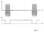
- den Signalverlauf bei einer vorteilhaften Auswertung des vollständigen Wechselsignals Ue.
- Fig. 1
- Components of a level or level measuring device with a preferred circuit arrangement and
- Fig. 2
- different signal waveforms in such an arrangement, in particular when evaluating only a half-wave.
- Fig. 3
- the waveform in an advantageous evaluation of the full alternating signal Ue.
Wie aus
Der Schwingkörper 2 ist über einen Schwingkörperanschluss 5 an die Schaltung 3 gekoppelt. Optional kann der Schwingkörperanschluss 5 als eine Steckverbindung ausgestaltet sein. Prinzipiell ist aber auch eine feste Verbindung der Schaltung 3 mit dem Schwingkörper 2 beim Einbau in dem eigentlichen Messgerät möglich.The oscillating
Die Schaltung 3 zeigt im Wesentlichen lediglich Komponenten, welche für das Verständnis für den konstruktiven Aufbau und die Verfahrensweise bei einer Signalverarbeitung gemäß dem besonders bevorzugten Konzept hilfreich sind. Die vorzugsweise zwei Anschlusskontakte des Schwingkörperanschlusses 5 sind ein Masse- bzw. Basisanschluss zum Anlegen einer Basisspannung bzw. einer Referenzspannung des Messgerätes sowie ein Signalanschluss, über welchen ein Sendesignal s bzw. ein Empfangssignal e übertragen werden.The circuit 3 essentially shows only components which are helpful for the understanding of the structural design and the procedure in a signal processing according to the particularly preferred concept. The preferably two connection contacts of the oscillating
An einen Ein- bzw. Ausgang der Schaltung 3, welcher mit dem Signalanschluss des Schwingungskörpers 2 verbindbar ist, ist ein Schalter 8 geschaltet, welcher den Schwingkörper 2 wahlweise mit einer Empfangsschaltung 6 oder einer Sendeschaltung 7 verbindet. Ein geeignetes Schaltsignal zum Schalten des Schalters 8 wird vorzugsweise von einem Prozessor 9 oder einer sonstigen geeigneten Schaltung bereitgestellt. Der Prozessor 9 ist bevorzugt als ein Mikrorechner ausgestaltet und dient als eine Modifizierungsschaltung.To an input or output of the circuit 3, which is connectable to the signal terminal of the
Die Empfangsschaltung 6 besteht ausgehend vom Anschluss am Schalter 8 vorzugsweise aus einem Filter 10, welchem das Empfangssignal e angelegt wird, welches vom Schwingkörper 2 bereitgestellt wird. Die Filterparameter des Filters 10 sind vorzugsweise mittels des Prozessors geeignet einstellbar. Ein vom Filter 10 ausgegebenes gefiltertes Signal wird an einen Verstärker 11 angelegt, welcher zum Verstärken des gefilterten Signals dient.The receiving circuit 6, starting from the connection at the
Ein derart verstärktes Signal wird vom Verstärker 11 an einen Komparator 12 angelegt, welcher insbesondere zum Durchführen einer Nulldurchgangsbestimmung ausgestaltet ist. Dies ermöglicht eine Frequenzmessung des Empfangssignals e, um so eine Eigenfrequenz fe bestimmen zu können. Die Eigenfrequenz fe wird vom Komparator 12 an den Prozessor 9 angelegt. Insbesondere wird die Eigenfrequenz fe an eine Zeitsteuereinrichtung 91 angelegt, welcher insbesondere als Bestandteil eines derartigen Prozessors 9 ausgebildet sein kann.Such an amplified signal is applied by the
Die Frequenz kann auch über FFT (Fast Fourier Transformation) bestimmt werden, indem das Signal direkt nach dem Filter bzw. ersten Verstärker per AD-Wandler eingelesen wird.The frequency can also be determined via FFT (Fast Fourier Transformation) by reading the signal directly after the filter or first amplifier via AD converter.
Außerdem wird von dem Verstärker 11 zur Messung der Amplitude des Empfangssignals e ein entsprechendes Messsignal an einen Analog-/Digital-Wandler 92 angelegt, welcher optional ebenfalls Bestandteil des Prozessors 9 sein kann. Über eine Schnittstelle 95 kann eine Kommunikation zu einer externen Einrichtung erfolgen, um z.B. Steueranweisungen zu empfangen oder Messdaten auszugeben.In addition, from the
Die Zeitsteuereinrichtung 91 kann vorzugsweise als eigene Komponente oder aber auch als Komponente einer übergeordneten Taktsteuerung 93 ausgestaltet sein. Außerdem ist ein Timer 94 vorgesehen, welcher ebenfalls als ein Bestandteil des Prozessors 9 bzw. einer entsprechenden Modifizierungseinrichtung als dem Prozessor 9 ausgebildet sein kann. Der Timer 94, welcher optional auch Bestandteil der Taktsteuerung 93 sein kann, dient zur Frequenzausgabe und insbesondere zum Ausgeben eines Taktsignals ts an eine Treiberstufe 13. Die Treiberstufe 13 stellt das Sendesignal s bereit, welches dem entsprechend geschalteten bzw. schaltbaren Anschluss des Schalters 8 angelegt wird.The
Ein sogenannter Step-up-DC/DC-Wandler stellt eine Treiberspannung Ud bereit, welche insbesondere der Treiberstufe 13 angelegt wird. Entsprechend kann die Treiberstufe die positive Treiberspannung +Ud bzw. die negative Treiberspannung -Ud an den Schalter 8 anlegen. Versorgt wird der Step-up-DC/DC-Wandler 14 mit einer Versorgungsspannung Vin, welche vorzugsweise auch einem linearen Regler 15 angelegt wird. Dieser dient zur Bereitstellung einer positiven Versorgungsspannung Vcc, welche unter anderem zur Versorgung des Prozessors 9 bzw. der Modifizierungsschaltung dient. Von dem Prozessor 9 bzw. der Modifizierungsschaltung wird eine programmierbare Treiberspannung Ut vorzugsweise dadurch angesteuert, dass ein Ein-/Aus-Signal für den Step-up-DC/DC-Wandler 14 bereitgestellt und diesem angelegt wird.A so-called step-up DC / DC converter provides a drive voltage Ud, which is applied to the
Der Prozessor 9 bzw. die durch diesen mitgebildete Modifizierungsschaltung weist somit insbesondere eine Eigenschwingungs-Bestimmungsanordnung in Form des Komparators 12 und weiterer Komponenten auf, welche die Eigenschwingung bzw. Eigenfrequenz fe des Schwingkörpers 2 mit seinem Schwingungsfühler (4) bestimmen. Anstelle der direkten Bestimmung eines Werts der Eigenfrequenz fe kann natürlich auch eine davon abhängige Größe te bestimmt werden, wie z. B. eine Taktdauer eines von dem Schwingkörper 2 empfangenen Signals. Weiterhin weist die Modifizierungsschaltung eine Sendesignal-Modifizierungsanordnung auf, welche insbesondere den Timer 94 in Verbindung mit der Treiberstufe 13 umfasst. Der Timer 94 gibt das Taktsignal ts als einen Sendetakt aus, welcher einer neuen Taktdauer entspricht, welche zur Erzeugung des nachfolgenden Sendesignals s verwendet wird. Abhängig von dieser neuen Taktdauer stellt die Treiberstufe 13 entsprechend ein Sendesignal s bereit, welches mit geeignet abfolgenden Impulsen den Schwingkörper 2 zu seiner Eigenfrequenz fe anregt, wobei vorzugsweise die Resonanzfrequenz mit dem Sendesignal s an den Schwingkörper 2 übertragen wird.The
In dem mittleren Zeitdiagramm ist der zeitliche Verlauf der Sendespannung Ud als an den Schalter 8 und den Schwingkörper 2 angelegtes Sendesignal s skizziert. Auch wenn dies anhand der verwendeten Skalierung nicht erkennbar ist, variiert üblicherweise insbesondere bei Betriebsbeginn die Taktdauer der Sendetakte ts von einem Sendezyklus zum nächsten Sendezyklus. Innerhalb der jeweiligen Sendedauer ds eines Sendezyklus/eines der Sendezyklen bleibt die Taktdauer bzw. das Taktsignal ts der Sendetakte vorzugsweise konstant.In the middle timing diagram, the time profile of the transmission voltage Ud is shown as being applied to the
Das unterste Diagramm zeigt das Empfangssignal e bzw. dessen beispielhaft gleichgerichtet dargestellte Empfangsspannung Ue. Erkennbar sind während der Empfangsdauer de jeweils mehrere empfangene Signale, welche hinsichtlich ihrer Dauer der Eigenfrequenz fe des Schwingkörpers 2 mit seinem Schwingungsfühler 4 entsprechen. Bestimmbar ist somit insbesondere als abhängige Größe te die Dauer bzw. Taktdauer der empfangenen Signale. Diese kann verwendet werden, um die Taktdauer des Taktsignals ts des Sendetakts für den vorzugsweise bereits nächsten Sendezyklus entsprechend anzupassen, so dass das Sendesignal s den Schwingkörper 2 mit vorzugsweise seiner Eigenfrequenz anregt.The bottom diagram shows the received signal e or its exemplary rectified receiving voltage Ue. In each case, a plurality of received signals can be recognized, which in terms of their duration correspond to the natural frequency fe of the
Bei einem entsprechenden Verfahrensablauf sendet der Prozessor 9 beispielsweise 100 Perioden mit einer beliebigen Frequenz an den Schwingkörper 2, welcher als Sender dient. Nach der Sendedauer dieser Anzahl von Perioden wird mittels des Schalters 8 auf einen Empfang umgeschaltet. Die Ausschwingfrequenz eines Schwingsystems ist stets die Eigenresonanz bzw. Eigenfrequenz fe und üblicherweise nicht die gesendete Frequenz. Ist die empfangene Amplitude des Empfangssignals e ausreichend groß, kann dessen Frequenz ermittelt werden, wobei die Frequenz der Eigenfrequenz fe entspricht. Nachfolgend wird die nächste Sendefrequenz als neue Sendefrequenz für das nachfolgende Sendesignal s entsprechend der derart ermittelten Eigenfrequenz fe festgelegt. Durch eine geeignete Regelung der Sendefrequenz kann die Schwingmechanik auf ihrer mechanischen Resonanzfrequenz betrieben werden.In a corresponding procedure, the
Soweit von einer Anregung des Schwingkörpers 2 bzw. dessen Empfangssignal e gesprochen wird, ist in der Praxis stets auch der Schwingungsfühler 4 mit zu betrachten, da diese einen wesentlichen Einfluss auf die Schwingcharakteristik der Schwingmechanik hat. Bis die mechanische Resonanzfrequenz bzw. Schwingfrequenz durch den Einsatz geeigneter Suchalgorithmen gefunden ist, muss beim nachfolgenden Betrieb lediglich die Sendefrequenz je nach Bedarf nachgeführt werden. Durch ein variables Verhältnis zwischen Senden und Empfangen werden breitbandige Sendesignale generiert, welche zur Erregung eines schmalbandigen Systems erforderlich sind.As far as an excitation of the vibrating
Claims (9)
dadurch gekennzeichnet, dass
characterized in that
gekennzeichnet durch
marked by
Priority Applications (2)
| Application Number | Priority Date | Filing Date | Title |
|---|---|---|---|
| EP08014195A EP2151672A1 (en) | 2008-08-08 | 2008-08-08 | Method for measuring a fill level or limit level, fill level or limit level measuring device control and fill level or limit level measuring device |
| US12/461,260 US8201447B2 (en) | 2008-08-08 | 2009-08-05 | Process for measuring a fill level or limit state, circuit for a device that measures a fill level or limit state, and device that measures a fill level or limit state |
Applications Claiming Priority (1)
| Application Number | Priority Date | Filing Date | Title |
|---|---|---|---|
| EP08014195A EP2151672A1 (en) | 2008-08-08 | 2008-08-08 | Method for measuring a fill level or limit level, fill level or limit level measuring device control and fill level or limit level measuring device |
Publications (1)
| Publication Number | Publication Date |
|---|---|
| EP2151672A1 true EP2151672A1 (en) | 2010-02-10 |
Family
ID=40347803
Family Applications (1)
| Application Number | Title | Priority Date | Filing Date |
|---|---|---|---|
| EP08014195A Withdrawn EP2151672A1 (en) | 2008-08-08 | 2008-08-08 | Method for measuring a fill level or limit level, fill level or limit level measuring device control and fill level or limit level measuring device |
Country Status (2)
| Country | Link |
|---|---|
| US (1) | US8201447B2 (en) |
| EP (1) | EP2151672A1 (en) |
Cited By (2)
| Publication number | Priority date | Publication date | Assignee | Title |
|---|---|---|---|---|
| WO2013097991A1 (en) * | 2011-12-28 | 2013-07-04 | Endress+Hauser Gmbh+Co. Kg | Device for determining and/or monitoring at least one process variable |
| DE102016111134A1 (en) * | 2016-06-17 | 2017-12-21 | Endress+Hauser Gmbh+Co. Kg | Vibronic sensor |
Families Citing this family (1)
| Publication number | Priority date | Publication date | Assignee | Title |
|---|---|---|---|---|
| EP3450933B1 (en) * | 2017-08-30 | 2022-07-06 | VEGA Grieshaber KG | Method of operating a fluid level threshold sensor |
Citations (10)
| Publication number | Priority date | Publication date | Assignee | Title |
|---|---|---|---|---|
| EP0568521A1 (en) * | 1992-04-29 | 1993-11-03 | Hans O. Univ.-Prof. Dr. Leopold | Device for determining density |
| DE4439879C1 (en) * | 1994-11-08 | 1996-02-01 | Grieshaber Vega Kg | Level sensor in form of vibration limit switch |
| DE69512652T2 (en) * | 1994-04-25 | 2000-04-27 | Sensor Systems (Jersey) Ltd., St. Helier | PIEZOELECTRIC MEASUREMENT METHOD |
| DE19930896A1 (en) * | 1997-04-08 | 2001-01-11 | Federal Ind Ind Group Inc | Vibrating probe in level detector for fluent material |
| EP1156305A2 (en) * | 2000-05-15 | 2001-11-21 | VEGA Grieshaber KG | Method for controlling a transducer arrangement in liquid level measurement apparatuses and device for curying out of the method |
| DE10161071A1 (en) * | 2001-12-12 | 2003-06-18 | Endress & Hauser Gmbh & Co Kg | Field electronic unit for process measurement technology in which a measurement sensor is provided with digital signal processing and control electronics to improve measurement accuracy and sensor reliability |
| WO2003050479A1 (en) * | 2001-12-12 | 2003-06-19 | Endress + Hauser Gmbh + Co.Kg | Electronic field device with a sensor unit for process measurement |
| DE10203461A1 (en) | 2002-01-28 | 2003-08-14 | Grieshaber Vega Kg | Vibration level sensor |
| EP1580539A1 (en) * | 2004-03-24 | 2005-09-28 | VEGA Grieshaber KG | Method for operating tests of vibration level sensors and corresponding vibration level sensor |
| US20060053863A1 (en) * | 2004-08-02 | 2006-03-16 | Karl Griessbaum | Self-diagnosis of a vibrating level gauge |
Family Cites Families (1)
| Publication number | Priority date | Publication date | Assignee | Title |
|---|---|---|---|---|
| JP4952356B2 (en) * | 2007-04-23 | 2012-06-13 | セイコーエプソン株式会社 | Liquid detection device, liquid ejection device, and liquid detection method |
-
2008
- 2008-08-08 EP EP08014195A patent/EP2151672A1/en not_active Withdrawn
-
2009
- 2009-08-05 US US12/461,260 patent/US8201447B2/en active Active
Patent Citations (10)
| Publication number | Priority date | Publication date | Assignee | Title |
|---|---|---|---|---|
| EP0568521A1 (en) * | 1992-04-29 | 1993-11-03 | Hans O. Univ.-Prof. Dr. Leopold | Device for determining density |
| DE69512652T2 (en) * | 1994-04-25 | 2000-04-27 | Sensor Systems (Jersey) Ltd., St. Helier | PIEZOELECTRIC MEASUREMENT METHOD |
| DE4439879C1 (en) * | 1994-11-08 | 1996-02-01 | Grieshaber Vega Kg | Level sensor in form of vibration limit switch |
| DE19930896A1 (en) * | 1997-04-08 | 2001-01-11 | Federal Ind Ind Group Inc | Vibrating probe in level detector for fluent material |
| EP1156305A2 (en) * | 2000-05-15 | 2001-11-21 | VEGA Grieshaber KG | Method for controlling a transducer arrangement in liquid level measurement apparatuses and device for curying out of the method |
| DE10161071A1 (en) * | 2001-12-12 | 2003-06-18 | Endress & Hauser Gmbh & Co Kg | Field electronic unit for process measurement technology in which a measurement sensor is provided with digital signal processing and control electronics to improve measurement accuracy and sensor reliability |
| WO2003050479A1 (en) * | 2001-12-12 | 2003-06-19 | Endress + Hauser Gmbh + Co.Kg | Electronic field device with a sensor unit for process measurement |
| DE10203461A1 (en) | 2002-01-28 | 2003-08-14 | Grieshaber Vega Kg | Vibration level sensor |
| EP1580539A1 (en) * | 2004-03-24 | 2005-09-28 | VEGA Grieshaber KG | Method for operating tests of vibration level sensors and corresponding vibration level sensor |
| US20060053863A1 (en) * | 2004-08-02 | 2006-03-16 | Karl Griessbaum | Self-diagnosis of a vibrating level gauge |
Cited By (5)
| Publication number | Priority date | Publication date | Assignee | Title |
|---|---|---|---|---|
| WO2013097991A1 (en) * | 2011-12-28 | 2013-07-04 | Endress+Hauser Gmbh+Co. Kg | Device for determining and/or monitoring at least one process variable |
| US9995617B2 (en) | 2011-12-28 | 2018-06-12 | Endress + Hauser Gmbh + Co. Kg | Measuring device with a mechanically oscillatable unit and an electrodynamic transducer unit |
| DE102016111134A1 (en) * | 2016-06-17 | 2017-12-21 | Endress+Hauser Gmbh+Co. Kg | Vibronic sensor |
| EP3472578B1 (en) * | 2016-06-17 | 2020-05-13 | Endress+Hauser SE+Co. KG | Vibronic sensor and method of operating a vibronic sensor |
| US11740116B2 (en) | 2016-06-17 | 2023-08-29 | Endress+Hauser SE+Co. KG | Vibronic sensor |
Also Published As
| Publication number | Publication date |
|---|---|
| US20100083751A1 (en) | 2010-04-08 |
| US8201447B2 (en) | 2012-06-19 |
Similar Documents
| Publication | Publication Date | Title |
|---|---|---|
| EP2499513B1 (en) | Method for operating at least one ultrasonic transducer | |
| DE102010039017B4 (en) | Method and device for active damping of an acoustic transducer | |
| EP1333256A2 (en) | Oscillating level sensor | |
| EP2320225B1 (en) | Method for adjusting ultrasound sensors | |
| EP3256822B1 (en) | Device for determining and/or monitoring at least one process variable for a medium and corresponding method | |
| DE102007008669A1 (en) | Method for determining and / or monitoring a process variable of a medium and corresponding device | |
| EP2564174A1 (en) | Device for determining and/or monitoring a process variable of a medium | |
| DE102010003624A1 (en) | Method for detecting fault of ultrasonic transducer utilized for detecting distance of car, involves comparing release time duration with another release time duration so as to detect fault in transducer | |
| EP2807499A1 (en) | Actuating circuit and method for actively damping an ultrasonic converter, and ultrasonic measuring system | |
| EP2151672A1 (en) | Method for measuring a fill level or limit level, fill level or limit level measuring device control and fill level or limit level measuring device | |
| WO1998053282A1 (en) | Vibration filling level limit switch and method for determining and/or monitoring the filling level of a medium in a container | |
| DE60207929T2 (en) | Feeding device and control method therefor | |
| EP1738837A3 (en) | Method and circuit arrangement for driving an ultrasonic vibrator | |
| EP3513152B1 (en) | Compensation of a phase shift of at least one electronic component of a vibronic sensor | |
| EP1745405B1 (en) | Transmission circuit for a transponder system used for transmitting a digital signal via a transmit antenna | |
| EP2861942B1 (en) | Method of operating a resonance measuring system and corresponding resonance measuring system | |
| DE10236735A1 (en) | Motor vehicle vibrating test bed control signal generation method is such that, the damage causing conditions of the test bed closely match those during actual driving | |
| WO2013091933A1 (en) | Method and circuit arrangement for activating an ultrasonic sensor | |
| DE102011116197A1 (en) | Method for recognizing roof rack mounted at right and left rail bar of roof rail in roof of motor car, involves making determination to check whether roof rack is mounted or not from measurement signal curves of piezo element | |
| EP0936740B1 (en) | Inductive proximity switch | |
| DE102004018506A1 (en) | Measuring device manufacturing method for determining and/or monitoring process factor, involves modifying vibration characteristics of mechanically vibrating unit if difference between its frequencies is greater than tolerance value | |
| EP0981202A2 (en) | Method of adjusting the transmitter frequency of an ultrasonic proximity switch and ultrasonic proximity switch having transmitter frequency adjustment | |
| EP2407801A1 (en) | Ultrasound measuring system for vehicle parking assist | |
| DE102022133045B4 (en) | compensation method for resonance detection | |
| DE102010062930A1 (en) | Method for detecting an object in an environment and device for generating an ultrasound signal |
Legal Events
| Date | Code | Title | Description |
|---|---|---|---|
| PUAI | Public reference made under article 153(3) epc to a published international application that has entered the european phase |
Free format text: ORIGINAL CODE: 0009012 |
|
| AK | Designated contracting states |
Kind code of ref document: A1 Designated state(s): AT BE BG CH CY CZ DE DK EE ES FI FR GB GR HR HU IE IS IT LI LT LU LV MC MT NL NO PL PT RO SE SI SK TR |
|
| AX | Request for extension of the european patent |
Extension state: AL BA MK RS |
|
| 17P | Request for examination filed |
Effective date: 20100323 |
|
| 17Q | First examination report despatched |
Effective date: 20100416 |
|
| AKX | Designation fees paid |
Designated state(s): AT BE BG CH CY CZ DE DK EE ES FI FR GB GR HR HU IE IS IT LI LT LU LV MC MT NL NO PL PT RO SE SI SK TR |
|
| STAA | Information on the status of an ep patent application or granted ep patent |
Free format text: STATUS: THE APPLICATION IS DEEMED TO BE WITHDRAWN |
|
| 18D | Application deemed to be withdrawn |
Effective date: 20160609 |