EP2151599A2 - Damper device - Google Patents
Damper device Download PDFInfo
- Publication number
- EP2151599A2 EP2151599A2 EP09167240A EP09167240A EP2151599A2 EP 2151599 A2 EP2151599 A2 EP 2151599A2 EP 09167240 A EP09167240 A EP 09167240A EP 09167240 A EP09167240 A EP 09167240A EP 2151599 A2 EP2151599 A2 EP 2151599A2
- Authority
- EP
- European Patent Office
- Prior art keywords
- plate
- damper
- hysteresis
- intermediate plate
- portions
- Prior art date
- Legal status (The legal status is an assumption and is not a legal conclusion. Google has not performed a legal analysis and makes no representation as to the accuracy of the status listed.)
- Withdrawn
Links
- 230000005540 biological transmission Effects 0.000 claims abstract description 51
- 239000002783 friction material Substances 0.000 description 71
- 239000006096 absorbing agent Substances 0.000 description 5
- 238000002485 combustion reaction Methods 0.000 description 5
- 239000011347 resin Substances 0.000 description 5
- 229920005989 resin Polymers 0.000 description 5
- 238000010586 diagram Methods 0.000 description 4
- 238000003466 welding Methods 0.000 description 3
- 238000006073 displacement reaction Methods 0.000 description 2
- 238000004519 manufacturing process Methods 0.000 description 2
- 238000013016 damping Methods 0.000 description 1
- 230000005611 electricity Effects 0.000 description 1
- 239000004519 grease Substances 0.000 description 1
- 230000004048 modification Effects 0.000 description 1
- 238000012986 modification Methods 0.000 description 1
Images


Classifications
-
- F—MECHANICAL ENGINEERING; LIGHTING; HEATING; WEAPONS; BLASTING
- F16—ENGINEERING ELEMENTS AND UNITS; GENERAL MEASURES FOR PRODUCING AND MAINTAINING EFFECTIVE FUNCTIONING OF MACHINES OR INSTALLATIONS; THERMAL INSULATION IN GENERAL
- F16F—SPRINGS; SHOCK-ABSORBERS; MEANS FOR DAMPING VIBRATION
- F16F15/00—Suppression of vibrations in systems; Means or arrangements for avoiding or reducing out-of-balance forces, e.g. due to motion
- F16F15/10—Suppression of vibrations in rotating systems by making use of members moving with the system
- F16F15/12—Suppression of vibrations in rotating systems by making use of members moving with the system using elastic members or friction-damping members, e.g. between a rotating shaft and a gyratory mass mounted thereon
- F16F15/121—Suppression of vibrations in rotating systems by making use of members moving with the system using elastic members or friction-damping members, e.g. between a rotating shaft and a gyratory mass mounted thereon using springs as elastic members, e.g. metallic springs
- F16F15/123—Wound springs
- F16F15/12353—Combinations of dampers, e.g. with multiple plates, multiple spring sets, i.e. complex configurations
- F16F15/1236—Combinations of dampers, e.g. with multiple plates, multiple spring sets, i.e. complex configurations resulting in a staged spring characteristic, e.g. with multiple intermediate plates
- F16F15/12366—Combinations of dampers, e.g. with multiple plates, multiple spring sets, i.e. complex configurations resulting in a staged spring characteristic, e.g. with multiple intermediate plates acting on multiple sets of springs
-
- F—MECHANICAL ENGINEERING; LIGHTING; HEATING; WEAPONS; BLASTING
- F16—ENGINEERING ELEMENTS AND UNITS; GENERAL MEASURES FOR PRODUCING AND MAINTAINING EFFECTIVE FUNCTIONING OF MACHINES OR INSTALLATIONS; THERMAL INSULATION IN GENERAL
- F16F—SPRINGS; SHOCK-ABSORBERS; MEANS FOR DAMPING VIBRATION
- F16F15/00—Suppression of vibrations in systems; Means or arrangements for avoiding or reducing out-of-balance forces, e.g. due to motion
- F16F15/10—Suppression of vibrations in rotating systems by making use of members moving with the system
- F16F15/12—Suppression of vibrations in rotating systems by making use of members moving with the system using elastic members or friction-damping members, e.g. between a rotating shaft and a gyratory mass mounted thereon
- F16F15/129—Suppression of vibrations in rotating systems by making use of members moving with the system using elastic members or friction-damping members, e.g. between a rotating shaft and a gyratory mass mounted thereon characterised by friction-damping means
- F16F15/1297—Overload protection, i.e. means for limiting torque
Definitions
- the present invention relates to a damper device for absorbing a torque fluctuation generated between rotational shafts. More specifically, the present invention relates to a damper device having damper portions arranged in series with each other.
- a damper device is arranged at a power transmission path between an engine and a clutch, for example, so as to absorb (reduces) a torque fluctuation generated between the engine and a transmission.
- the damper device absorbs (reduces) torsion (the torque fluctuation) by means of elastic force of coil springs and friction force (hysteresis torque) generated by friction materials.
- a conventional damper device includes two kinds of damper portions (coil springs and elastic members), each of which is arranged in series with each other, in order to absorb (reduces) a torque fluctuation in accordance with a driving state of an engine (for example, at the time when the engine is started, and at the time when the engine is in an idling state).
- a torque fluctuation absorber absorbs a torque fluctuation of a driving source in a hybrid vehicle having both an internal combustion engine and an electric motor, which is driven by means of electricity supplied from a battery, as the driving source, and an electric generator, which is configured to charge the battery with an electrical energy generated by driving the internal combustion engine.
- the torque fluctuation absorber is configured to absorb the torque fluctuation of the internal combustion engine by means of a first torsion member and a second torsion member, whose torsional rigidity is larger than the first torsion member.
- the torsional rigidity of the first torsion member is set to absorb a torque fluctuation of the internal combustion engine, the torque fluctuation being generated when the electric generator generates the electrical energy by means of the internal combustion engine.
- the first torsion member which is provided at a radially inward portion, is arranged between a flange portion and a hub portion.
- the first torsion member of the torque fluctuation absorber is limited to absorb a small amount of torque. Accordingly, a performance of absorbing the torque fluctuation by means of the first torsion member is achieved only when the small amount of torque is generated from the engine that is in the idling state and the like. Further, a torsion angle may not be set to be large at a position where the first torsion member is arranged, and therefore, the torsional rigidity is set at a high level so as to absorb only a relatively small amount of torque.
- the first torsion member is arranged at a space between an inner spline of the flange portion and an outer spline of the hub portion in a circumferential direction. Therefore, only a part of end surfaces of the first torsion member contact the inner spline of the flange portion and the outer spline of the hub portion, and as a result, strength is limited and an impact is easily generated. Furthermore, splines are formed at the flange portion and the hub portion. Therefore, a processing cost is increased.
- the hub portion which is arranged at an output side, may include a large amount of inertia in order to absorb noise and vibration.
- the hub portion is arranged at a more radially inward portion than the flange portion, and therefore, inertia of the hub portion may not be set to a large level.
- a damper device inputting torque of a power source from an input side and outputting the torque to an output side
- the damper device includes a plurality of damper portions arranged in series with each other in a power transmission path and absorbing torsion by means of elastic force, a plurality of hysteresis portions arranged in parallel with the plurality of damper portions at the power transmission path and absorbing the torsion by means of friction force, an input plate inputting rotational torque into one of the damper portion closest to the input side among the plurality of damper portions and the hysteresis portion closest to the input side among the plurality of hysteresis portions, an intermediate plate transmitting the rotational torque from the damper portion, arranged at the input side, and the hysteresis portion, arranged at the input side, to the damper portions, arranged at the output side, and the hysteresis portions, arranged at the output side, at a position between the damper portion closest to
- the hysteresis portions include different hysteresis torque values, respectively.
- the damper device further includes a limiter portion sliding when a torsion reaches a level where the torsion is not absorbed by the damper portions and the hysteresis portions in the power transmission path.
- the limiter portion is arranged to be closer to the input side than the damper portion closest to the input side among the plurality of damper portions and the hysteresis portion closest to the input side among the plurality of hysteresis portions, in the power transmission path.
- the damper device further includes the limiter portion sliding when a torsion reaches a level where the torsion is not absorbed by the damper portions and the hysteresis portions in the power transmission path,
- the limiter portion is arranged in the power transmission path between the damper portion closest to the input side and the damper portion closest to the output side and between the hysteresis portion closest to the input side and the hysteresis portion closest to the output side.
- the limiter portion is provided at the intermediate plate.
- the damper device further includes a limiter portion sliding when a torsion reaches a level where the torsion is not absorbed by the damper portions and the hysteresis portions in the power transmission path.
- the limiter portion is arranged to be closer to the output side than the damper portion closest to the output side among the plurality of damper portions and the hysteresis portion closest to the output side among the plurality of hysteresis portions, in the power transmission path.
- the limiter portion is arranged at a position radially corresponding to the damper portion, arranged at the radially most outward position among the plurality of damper portions, or at a radially more outward position than the damper portion, arranged at the radially most outward position among the plurality of damper portions.
- the damper device further includes a first rotational shaft outputting rotational torque of an engine to an outside of the engine, a hub connected to a second rotational shaft at an outer circumference thereof and arranged to be closer to the output side than the damper portion closest to the output side among the plurality of damper portions and the hysteresis portion closest to the output side among the plurality of hysteresis portions, in the power transmission path, and a guide guiding one of the first rotational shaft, a connecting plate connected to the first rotational shaft, the input plate, the intermediate plate and the output plate so as to be rotatable relative to the hub.
- the guide commonly guides two or more of the first rotational shaft, the connecting plate connected to the first rotational shaft, the input plate, the intermediate plate and the output plate.
- the guide is arranged between two of the input plate, the intermediate plate and the output plate, while functioning as a component of one of the hysteresis portions.
- the output plate includes a portion extending radially more outwardly than a rotational torque receiving portion of the damper portion closest to the output side among the plurality of damper portions and a rotational torque receiving portion of the hysteresis portion closest to the output side among the plurality of hysteresis portions.
- At least two of the damper portions are arranged at positions displaced from each other in an axial direction.
- a plurality of plates of one of the input plate, the intermediate plate and the output plate is riveted by means of a rivet and at least one of the input plate, the intermediate plate and the output plate includes an opening portion at a position corresponding to the rivet in the axial direction.
- one of the damper portions includes a coil spring and a pair of resin-made seat, one of the resin-made seat is arranged at one end portion of the coil spring and the other of the resin-made seat is arranged at the other end portion of the coil spring.
- the damper portions and the hysteresis portions are covered by a covering member and lubricated by oil.
- the first and second damper portions 3a and 3c absorb the torsion generated by a relative rotation between the input plate 6, 13, 37, 38, 62, 70, 71, 82, 121 and 126 and the intermediate 7, 16, 17, 42, 48, 49, 63, 72, 73, 74, 75, 76, 83, 89, 90, 100, 101, 102, 104, 105, 106, 111, 112, 113, 114, 122, 123, 127, 128 and 130 and between the intermediate plate 7, 16, 17, 42, 48, 49, 63, 72, 73, 74, 75, 76, 83, 89, 90, 100, 101, 102, 104, 105, 106, 111, 112, 113, 114, 122, 123, 127, 128 and 130 and the output plate 8, 27, 43, 44, 47, 66, 67, 91, 97 and 116.
- a torsional rigidity may be set at a relatively low level so as to absorb a high torque.
- the inertia of the output plate 8, 27, 43, 44, 47, 66, 67, 91, 97 and 116 is structurally set to be large. Therefore, performance of absorbing noise and vibrations is increased.
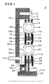
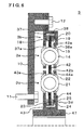
- Fig. 1 is a cross-sectional view schematically illustrating a configuration of a damper device according to embodiment 1;
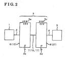
- Fig. 2 is a schematic view (a skeleton diagram) illustrating a configuration in which the damper device according to embodiment 1 is provided between an engine and a component having a large amount of inertia;
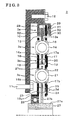
- Fig. 3 is a cross-sectional view schematically illustrating the configuration of the damper device according to a modified example (embodiment 1-1) of embodiment 1;
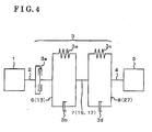
- Fig. 4 is a schematic view (a skeleton diagram) illustrating the configuration in which the damper device according to the modified example (embodiment 1-1) of embodiment 1 is provided between the engine and the component having the large amount of inertia;
- Fig. 5 a cross-sectional view schematically illustrating the configuration of the damper device according to a modified example (embodiment 1-2) of the embodiment 1;
- Fig. 6 a cross-sectional view schematically illustrating the configuration, of the damper device according to embodiment 2;
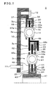
- Fig. 7 is a cross-sectional view schematically illustrating the configuration of the damper device according to a modified example (embodiment 2-1) of the embodiment 2;
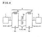
- Fig. 8 is a schematic view (a skeleton diagram) illustrating the configuration in which the damper device according to the modified example (embodiment 2-1) of embodiment 2 is provided between the engine and the component having the large amount of inertia;
- Fig. 9 a cross-sectional view schematically illustrating the configuration of the damper device according to a modified example (embodiment 2-2) of embodiment 2;
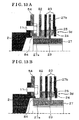
- Fig. 10 is a cross-sectional view schematically illustrating the configuration of the damper device according to embodiment 3.
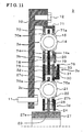
- Fig. 11 is a cross-sectional view schematically illustrating the configuration of the damper device according to a modified example (embodiment 3-1) of embodiment 3;
- Fig. 12 is a cross-sectional view schematically illustrating the configuration of the damper device according to a modified example (embodiment 3-2) of embodiment 3;
- Fig. 13A is a first cross-sectional view schematically illustrating the configuration of the damper device according to a modified example (embodiment 3-3) of embodiment 3;
- Fig. 13B is a second cross-sectional view schematically illustrating the configuration of the damper device according to the modified example (embodiment 3-3) of embodiment 3;
- Fig. 14 is a cross-sectional view schematically illustrating the configuration of the damper device according to a modified example (embodiment 3-4) of embodiment 3;
- Fig. 15A is a first cross-sectional view schematically illustrating the configuration of the damper device according to a modified example (embodiment 3-5) of embodiment 3;
- Fig. 15B is a second cross-sectional view schematically illustrating the configuration of the damper device according to the modified example (embodiment 3-5) of embodiment 3;
- Fig. 16 is a cross-sectional view schematically illustrating the configuration of the damper device according to embodiment 4.
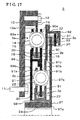
- Fig. 17 is a cross-sectional view schematically illustrating the configuration of the damper device according to a modified example (embodiment 4-1) of embodiment 4;
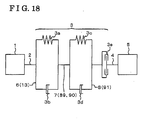
- Fig. 18 is a schematic view (a skeleton diagram) illustrating the configuration in which the damper device according to the modified example (embodiment 4-1) of embodiment 4 is provided between the engine and the component having the large amount of inertia;
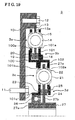
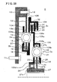
- Fig. 19 is a cross-sectional view schematically illustrating the configuration of the damper device according to embodiment 5;
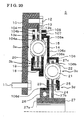
- Fig. 20 is a cross-sectional view schematically illustrating the configuration of the damper device according to embodiment 6;
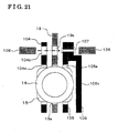
- Fig. 21 is an enlarged cross-sectional view schematically illustrating the configuration of a portion surrounding a rivet of the damper device according embodiment 6;
- Fig. 22 is a cross-sectional view schematically illustrating the configuration of the damper device according to a modified example (embodiment 6-1) of embodiment 6;
- Fig. 23 is a cross-sectional view schematically illustrating the configuration of the damper device according to a modified example (embodiment 6-2) of embodiment 6;
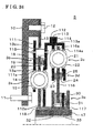
- Fig. 24 is a cross-sectional view schematically illustrating the configuration of the damper device according to a modified example (embodiment 6-3) of embodiment 6;
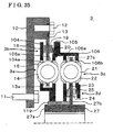
- Fig. 25 is a cross-sectional view schematically illustrating the configuration of the damper device according to a modified example (embodiment 6-4) of embodiment 6;
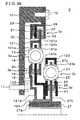
- Fig. 26 is a cross-sectional view schematically illustrating the configuration of the damper device according to embodiment 7.
- Fig. 27 is a cross-sectional view schematically illustrating the configuration of the damper device according to embodiment 8.
- a damper device 3 inputting torque of a power source 1 from an input side and outputting the torque to an output side includes a plurality of damper portions (3a, 3c) arranged in series with each other in a power transmission path and absorbing torsion by means of elastic force, a plurality of hysteresis portions (3b, 3d) arranged in parallel with the plurality of damper portions (3a, 3c) at the power transmission path and absorbing the torsion by means of friction force, an input plate (13) inputting rotational torque into one of the damper portion (3a, 3c) closest to the input side among the plurality of damper portions (3a, 3c) and the hysteresis portion (3b, 3d) closest to the input side among the plurality of hysteresis portions (3b 3d), an intermediate plate (16, 17) transmitting the rotational torque from the damper portion (3a, 3c), arranged at the input side, and the hysteresis portion (3b, 3d
- first damper portion 3a one first damper portion 3a, one second damper portion 3c, one first hysteresis portion 3b and one second hysteresis portion 3d are described in order to simplify an explanation.
- the number of the first damper portion 3a, the second damper portion 3c, the first hysteresis portion 3b, the second hysteresis portion 3d are not limited to the following description, and a modification will be made.
- axial direction hereinafter corresponds to an axial direction of a rotational shaft of an engine (a rotational shaft of a component having a large amount of inertia), while “circumferential direction” corresponds to a circumferential direction of each plate and “radial direction” corresponds to a radial direction of each of the plate, unless otherwise indicated.
- Embodiment 1 of the damper device 3 will be described hereinafter with reference to the attached drawings.
- the damper device 3 As illustrated in Fig. 2 , the damper device 3 according the embodiment 1 is provided, for example, between the first rotational shaft 2 of an engine 1 (a power source) and the second rotational shaft 4 of a component 5 (a clutch drum of an automatic transmission, a pulley of a Continuously Variable Transmission (CVT), a motor of a hybrid vehicle, and the like) having a large amount of inertia.
- the damper device 3 absorbs (restricts) a torque fluctuation generated by torsion of the first rotational shaft 2 and the second rotational shaft 4.
- the damper device 3 having a torsion-damping function, includes the first damper portion 3a, the second damper portion 3c, the first hysteresis portion 3b and the second hysteresis portion 3d.
- the first damper portion 3a and the second damper portion 3c absorb the torque fluctuation by means of the elastic force.
- the first hysteresis portion 3b and the second hysteresis portion 3d absorb (restrict) the torque fluctuation by means of the hysteresis torque, such as a friction force and the like.
- the first damper portion 3a and the second damper portion 3c are arranged to be in series with each other, A rotational torque of the first rotational shaft 2 is inputted into the first damper portion 3a via the input plate 6, and the first damper portion 3a then outputs a rotational torque thereof to the second damper portion 3c.
- the rotational torque of the first damper portion 3a is inputted into the second damper portion 3c via the intermediate plate 7, and the second damper portion 3c then outputs a rotational torque thereof to the second rotational shaft 4 via the output plate 8.
- the first damper portion 3a and the first hysteresis portion 3b are arranged to be in parallel with each other.
- the second damper portion 3c and the second hysteresis portion 3d are arranged to be in parallel with each other.
- a maximum torsion torque of one of first and second damper portions 3a and 3c is set to be equal to or more than an engine torque.
- a maximum torsion torque of the other of first and second damper portions 3a and 3c is set to be a torsion torque equal to or more than half of the engine torque.
- the maximum torsion torque of both of the first and second damper portions 3a and 3b are set to be the torsion torque equal to or more than the engine torque.
- the first and second hysteresis portions 3b and 3d may be set to include different hysteresis torque values.
- a hysteresis torque value of one of the first and second hysteresis portions 3b and 3d may be set to be equal to or more than three times of a hysteresis torque value of the other of the first and second hysteresis portions 3b and 3d.
- a large vibration such as a vibration generated when the engine 1 is started and the like
- a small vibration such as a vibration generated when a vehicle is driven and the like
- a small vibration is absorbed by means of the hysteresis portion, having the smaller hysteresis torque value.
- the damper device 3 includes an input plate 13, first and second intermediate plates 16 and 17 and an output plate (a hub 27).
- the damper device 3 includes a first plate 10 (a connecting plate), first and second bolts 11 and 12, the input plate 13, a first coil spring 14 (an arc spring), a pair of first seat 15, the first and second intermediate plates 16 and 17, first and second thrust members 18 and 19, a first coned disc spring 20, a second coil spring 21 (an arc spring), a pair of second seat 22, third and fourth thrust members 23 and 24, a second coned disc spring 25, a bearing 26 (a guide) and the hub 27.
- the first plate 10 formed into a substantially circular-shape, is fixed at, for example, the first rotational shaft 2 (see Fig. 2 ) of the engine 1 (see Fig. 2 ) by means of the first bolt 11.
- the first plate 10 includes a cylindrical portion, which protrudes from a vicinity of a radially outward end of the first plate 10 toward one side of an axial direction (toward a right side in Fig. 1 ).
- the input plate 13 is fixed at a surface of the cylindrical portion, the surface extending to be substantially orthogonal relative to the axial direction.
- the input plate 13 formed into a substantially-circular shape, inputs a rotational torque to the first damper portion 3a and the first hysteresis portion 3b.
- the input plate 13 is fixed to the first plate 10 in the vicinity of a radially outward end portion of the input plate 13 by means of the second bolt 12.
- the input plate 13 is arranged between the first and second intermediate plates 16 and 17 to be spaced away therefrom.
- the input plate 13 is provided in such a way that end surfaces of the first opening portion 13a in the circumferential direction contact/spaced away from the pair of first seat 15 respectively.
- the input plate 13 is slidably sandwiched between the first and second thrust members 18 and 19 at the first hysteresis portion 3b, which is arranged at a radially more inward portion of the first plate 13 than the first damper portion 3a.
- the first coil spring 14 is a component of the first damper portion 3a.
- the first coil spring 14 is accommodated in the first opening portion 13a, a second opening portion 16a and a third opening portion 17a, which are formed at the input plate 13, the first intermediate plate 16 and the second intermediate plate 17, respectively, so as to contact the pair of first seat 15, which is respectively arranged at end portions of the first coil spring 14.
- the first coil spring 14 is compressed when the input plate 13 is rotated relative to the first and second intermediate plates 16 and 17 so as to absorb an impact generated by a rotational difference between the input plate 13 and the first and second intermediate plates 16 and 17,
- a straight-shaped spring whose compressed direction extends in a straight line, or a straight-shaped bent spring, whose compressed direction extends in a straight line but being bent when being arranged, may be applied to the first coil spring 14.
- An arc spring whose compressed direction extends along the circumferential direction, may be applied to the first coil spring 14 in order to absorb a greater amount of torsion torque.
- the pair of first seat 15 is a component of the first damper portion 3a.
- the pair of first seat 15 is accommodated in the first, second and third opening portions 13a, 16a and 17a, which are formed at the input plate 13, the first intermediate plate 16 and the second intermediate plate 17, respectively.
- One of the first seat 15 is arranged between one end portion of the first coil spring 14 and one end surface of each of the first, second and third opening portions 13a, 16a and 17a in the circumferential direction.
- the other of the first seat 15 is arranged between the other end portion of the first coil spring 14 and the other end surface of each of the first, second and third opening portions 13a, 16a and 17a in the circumferential direction.
- the pair of first seat 15 may be made of a resin in order to reduce attrition of the first coil spring 14.
- the first intermediate plate 16 formed into a substantially circular-shape, outputs a rotational torque, inputted by the first damper portion 3a and the first hysteresis portion 3b, while inputting the rotational torque into the second damper portion 3c and the second hysteresis portion 3d.
- the first intermediate plate 16 is connected to the second intermediate plate 17 by means of a rivet, and the like so as to be integrally rotated with the second intermediate plate 17.
- the second opening portion 16a for accommodating the first coil spring 14 and the pair of first seat 15, is formed at a radially outward portion of the first intermediate plate 16, corresponding to the first damper portion 3a.
- the first intermediate plate 16 is provided in such a way that end surfaces of the second opening portion 16a in the circumferential direction contact/spaced away from the pair of first seat 15.
- the first intermediate plate 16 is press-fitted with the first thrust member 18 at the first hysteresis portion 3b, which is arranged at a radially more inward portion of the first intermediate plate 16 than the first damper portion 3a, so that the first intermediate plate 16 slides on the first thrust member 18.
- a fourth opening portion 16b for accommodating the second coil spring 21 and the pair of second seat 22, is formed at a radially more inward portion of the first intermediate plate 16 than the first hysteresis portion 3b, corresponding to the second damper portion 3c.
- the first intermediate plate 16 is provide in such a way that end surfaces of the fourth opening portion 16b in the circumferential direction contact/spaced away from the pair of second seat 22.
- the first intermediate plate 16 is slidably press-fitted with the third thrust member 23 at the second hysteresis portion 3d, which is arranged at a radially more inward portion of the first intermediate plate 16 than the second damper portion 3c.
- the first intermediate plate 16 includes a cylindrical portion 16c, which is formed at a radially inward end of the first intermediate plate 16.
- the first intermediate plate 16 is supported by the hub 27 via the bearing 26 at an inner circumferential surface of the cylindrical portion 16c, so that the first intermediate plate 16 is rotatable relative to the hub 27.
- the second intermediate plate 17 is connected to the first intermediate plate 16 by means of the rivet, and the like so as to be integrally rotated with the first intermediate plate 16.
- the third opening portion 17a, for accommodating the first coil spring 14 and the pair of first seat 15, is formed at a radially outward portion of the second intermediate plate 17, corresponding to the first damper portion 3a.
- the second intermediate plate 17 is provided in such a way that end surfaces of the third opening portion 17a in the circumferential direction contact/spaced away from the pair of first seat 15.
- the second intermediate plate 17 supports the first coned disc spring 20 at the first hysteresis portion 3b, which is arranged at a radially more inward portion of the second intermediate plate 17 than the first damper portion 3a.
- the second intermediate plate 17 is provided in such a way that end surfaces of the fifth opening portion 17b in the circumferential direction contact/spaced away from the pair of second seat 22.
- the second intermediate plate 17 supports the second coned disc spring 25 at the second hysteresis portion 3d, which is arranged at a radially more inward portion of the second intermediate plate 17 than the second damper portion 3a.
- the first thrust member 18 is a component of the first hysteresis portion 3b, and is a substantially circular-shaped friction material arranged between the input plate 13 and the first intermediate plate 16.
- the first thrust member 18 is slidably press-fitted with the input plate 13 and with the first intermediate plate 16.
- the second thrust member 19 is a component of the first hysteresis portion 3b.
- the second thrust member 19 is a friction material formed into a substantially circular-shape.
- the second thrust member 19 is sandwiched between the input plate 13 and the second intermediate plate 17.
- the second thrust member 19 is biased by means of the first coned disc spring 20 from a direction of the second intermediate plate 17.
- the second thrust member 19 is slidably press-fitted with the input plate 13.
- the first coned disc spring 20 is a component of the first hysteresis portion 3b.
- the first coned disc spring 20 is sandwiched between the second thrust member 19 and the second intermediate plate 17.
- the second coil spring 21 is a component of the second damper portion 3c.
- the second coil spring 21 is accommodated in the fourth opening portion 16b, the fifth opening portion 17b and a sixth opening portion 27c, which are formed at the first intermediate plate 16, the second intermediate plate 17 and an output plate 27b of the hub 27, respectively, so as to contact the pair of second seat 22, which is respectively arranged at end portions of the second coil spring 21.
- the second coil spring 21 is compressed, when the first and second intermediate plates 16 and 17 are rotated relative to the hub 27, so as to absorb an impact generated by a rotational difference between the first and second intermediate plates 16 and 17 and the .hub 27.
- a straight-shaped spring whose compressed direction extends in a straight line, or a straight-shaped bent spring, whose compressed direction extends in a straight line but being bent when being arranged, may be applied to the second coil spring 21.
- An arc spring whose compressed direction extends along the circumferential direction, may be applied to the first coil spring 14 in order to absorb a greater amount of torsion torque.
- the pair of second seat 22 is a component of the second damper portion 3c.
- the pair of second seat 22 is accommodated in the fourth, fifth and sixth opening portions 16b, 17b and 27c, which are formed at the first intermediate plate 16, the second intermediate plate 17 and the hub 27, respectively.
- the pair of second seat 22 is arranged between end portions of the second coil spring 21 and end surfaces of each of the fourth, fifth and sixth opening portions 16b, 17b, and 27c in the circumferential direction.
- the second seat 15 may be made of a resin in order to reduce attrition of the second coil spring 21.
- the third thrust member 23 is a component of the second hysteresis portion 3d.
- the third thrust member 23 is a friction material formed into a substantially circular-shape.
- the third thrust member 23 is sandwiched between the first intermediate plate 16 and the output plate 27b of the hub 27.
- the third thrust member 23 is slidably press-fitted with the output plate 27b.
- the fourth thrust member 24 is a component of the second hysteresis portion 3d.
- the fourth thrust member 24 is a friction material formed into a substantially circular-shape.
- the fourth thrust member 24 is sandwiched between the second intermediate plate 17 and the output plate 27b of the hub 27.
- the fourth thrust member 24 is biased by means of the second coned disc spring 25 from the direction of the second intermediate plate 17.
- the fourth thrust member 24 is slidably press-fitted with the output plate 27b.
- the second coned disc spring 25 is a component of the second hysteresis portion 3d.
- the second coned disc spring 25 is sandwiched between the fourth thrust member 24 and the second intermediate plate 17.
- the bearing 26 is a guide member for rotatably supporting the first intermediate plate 16 relative to the hub 27 at the inner circumference of the cylindrical portion 16c of the first intermediate plate 16.
- Another bearing such as a bush and the like, may be used instead of the bearing 26,
- the hub 27 outputs a rotational torque inputted by the second damper portion 3c and the second hysteresis portion 3d.
- the hub 27 includes the output plate 27b extending from a predetermined portion of an outer circumference of a hub portion 27a.
- a spline for being connected to the second rotational shaft 4 (see Fig. 2 ) is formed at an inner circumferential surface of the hub portion 27a.
- the hub portion 27a supports the first intermediate plate 16 via the bearing 26 so that the first intermediate plate 16 is rotatable relative to the hub 27,
- a sixth opening portion 27c, for accommodating the second coil spring 21 and the pair of second seat 22, is formed at a radially outward portion of the output plate 27b, corresponding to the second damper portion 3b.
- the output plate 27b is provided in such a way that end surfaces of the sixth opening portion 27c in the circumferential direction contact/spaced away from the pair of second seat 22.
- the output plate 27b is slidably sandwiched between the third and fourth thrust members 23 and 24 at surfaces of the second hysteresis portion 3d, which is arranged at a radially more inward portion of the output plate 27b than the second damper portion 3b, the surfaces extending to be substantially orthogonal relative to the axial direction.
- the hub 27, serving as the output plate includes the output plate portion 27b. Therefore, inertia of the hub 27 is structurally set to be large, and consequently, performance of absorbing noise and vibration may be improved.
- the first damper portion 3a is configured to absorb a torsion generated by a relative rotation between the first opening portion 13a of the input plate 13 and the second and third opening portions 16a and 17a of the first and second intermediate plates 16 and 17 (the second damper portion 3c is configured to absorb a torsion generated by a relative rotation between the sixth opening portion 27c of the hub 27 and the fourth and fifth opening portions 16b and 17b of the first and second intermediate plates 16 and 17).
- a torsion angle may be increased and a torsional rigidity may be set to a relatively low level so as to absorb a high torque.
- the bearing 26 is provided between the first intermediate plate 16 and the hub 27. Therefore, eccentricity of the first intermediate plate 16 may be prevented.
- the damper device 3 according to embodiment 1-1 includes a limiter portion 3e (see Fig. 4 ).
- the limiter portion 3e is provided at a power transmission path between the first rotational shaft 2 and the first damper portion 3a so as to slide when a torsion generated between the first and second rotational shafts 2 and 4 reaches a level where the torsion is not absorbed by the first and second damper portions 3a and 3c and by the first and second hysteresis portions 3b and 3d.
- Other configurations of the damper device 3 according to embodiment 1-1 are similar to the damper device 3 according to embodiment 1 (see Fig. 1 ).
- the damper device 3 includes the limiter portion 3e at a radially more outward portion thereof than the first damper portion 3a (see Fig. 3 ).
- the limiter portion 3e may slide with an approximately 1.2 to 3 times greater torque than the engine torque.
- the damper device 3 includes second and third plates 28 and 29, a pressure plate 30, a third coned disc spring 31, first and second friction materials 32 and 33 and the input plate 13, as components of the limiter portion 3e.
- the second plate 28, formed into a substantially circular-shape, is arranged between the first plate 10 and the third plate 29.
- the second plate 28 contacts the third plate 29 at a radially outward portion thereof, and the second plate 28 together with the third plate 29 are fixed at the first plate 10 by means of the second bolt 12.
- the second plate 28 is slidably press-fitted with the first friction material 32.
- the third plate 29, formed into a substantially circular-shape, is arranged at a position more distant from the first plate 10 than the second plate 28 in the axial direction.
- the third plate 29 contacts the second plate 28 at an outer circumferential portion thereof, and the third plate 29 together with the second plate 28 are fixed at the first plate 10 by means of the second bolt 12.
- the third plate 29 supports the pressure plate 30 and the third coned disc spring 31 so as to restrict relative rotation between the third plate 29 and each of the pressure plate 30 and the third coned disc spring 31, and so that the pressure plate 30 and the third coned disc spring 31 are movable in the axial direction.
- the third plate 29 is press-fitted with the third coned disc spring 31.
- the pressure plate 30 is supported by the third plate 29 so as to be movable in the axial direction but so as not to be rotatable relative to the third plate 29.
- the pressure plate 30 is biased by the third coned disc spring 31 toward the second friction material 33, and the pressure plate 30 is slidably press-fitted with the second friction material 33.
- the third coned disc spring 31 formed into a substantially diso-shape, is arranged between the third plate 29 and the pressure plate 30.
- the third coned disc spring 31 biases the pressure plate 30 toward the second friction material 33.
- the third coned disc spring 31 is supported by the third plate 29 so as to be movable in the axial direction but so as not to be rotated relative to the third plate 29.
- the first friction material 32 is arranged between the input plate 13 and the second plate 28.
- the first friction material 32 together with the second friction material 33 are fixed at the input plate 13 by means of a rivet, and the like.
- the first friction material 32 is slidably press-fitted with the second plate 28.
- the second friction material 33 is arranged between the pressure plate 30 and the input plate 13.
- the second friction material 33 together with the first friction material 32 are fixed at the input plate 13 by means of the rivet, and the like.
- the second friction material 33 is slidably press-fitted with the pressure plate 30.
- the input plate 13 according to the embodiment 1-1 is not fixed at the first plate 10 at a radially more outward portion of the input plate 13 than the first damper portion 3a.
- a radially more outward portion of the input plate 13 than the first damper portion 3a is arranged between the first and second friction materials 32 and 33, and the first and second friction materials 32 and 33 are fixed at the input plate 13 by means of the rivet, and the like (see Fig. 3 ).
- Other configurations of the input plate 13 according to the embodiment 1-1 are similar to the input plate 13 according to embodiment 1 (see Fig. 1 ).
- the limiter portion 3e is provided. Therefore, an excessive torque is reduced, and as a result, a possibility of damaging the damper device 3 may be reduced. Further, the limiter portion 3e is arranged at the power transmission path between the first rotational shaft 2 (see Fig. 4 ), and the first damper portion 3a.
- the limiter portion 3e is provided at a radially outward portion the damper device 3, and as a result, a torque is easily set (for example, a torque, which is absorbed by the limiter portion 3e, may be easily set because a load required to be applied to the pressure plate 30 by the third coned disc spring 31 is reduced when the limiter portion 3e is provided at a radially outward portion of the damper device 3.).
- a configuration of the second and third plates 28 and 29 according to embodiment 1-1 is modified (see Fig. 5 ), so that the first and second damper portions 3a and 3c, the first and second hysteresis portions 3b and 3d and the limiter portion 3e may be positioned within the space enclosed by the second plate 28 and the third plate 29, and the space is filled with oil (including grease) so as to lubricate the first and second damper portions 3a and 3c, the first and second hysteresis portions 3b and 3d and the limiter portion 3e.
- the second plate 28 (a covering member) extends to the outer circumference of the hub portion 27a of the hub 27 (a covering member).
- a first seal 34 (a covering member) is provided between an inner circumferential end of the second plate 28 and the hub portion 27a.
- the third plate 29 (a covering member) extends to the outer circumference of the hub portion 27a of the hub 27.
- a second seal 35 (a covering member) is provided between an inner circumferential end of the third plate 29 and the hub portion 27a.
- Other configurations of the damper device 3 according to embodiment 1-2 are similar to the configuration of the damper device 3 according to embodiment 1-1 (see Figs. 3 and 4 ).
- the damper device 3 includes first and second input plates 37 and 38, an intermediate plate 42 and first and second output plates 43 and 44.
- the damper device 3 includes the first plate 10, the first and second bolts 11 and 12, the first and second input plates 37 and 38, the first coil spring 14, the pair of first seat 15, the intermediate plate 42, the first and second thrust members 18 and 19, the first coned disc spring 20, the second coil spring 21, the pair of second seat 22, the third and fourth thrust members 23 and 24, the second coned disc spring 25, the first and second output plates 43 and 44 and a hub 47.
- the first plate 10, the first and second bolts 11 and 12, the first coil spring 14, the pair of first seat 15, the first and second thrust members 18 and 19, the first coned disc spring 20, the second coil spring 21, the pair of second seat 22, the third and fourth thrust members 23 and 24 and the second coned disc spring 25 are similar to embodiment 1 (see Fig. 1 ). Further, the configuration of the damper device 3 according to embodiment 2 is similar to the configuration of the damper device 3 shown in Fig. 2 .
- the first input plate 37 formed into a substantially circular-shape, inputs the rotational torque to the first damper portion 3a and the first hysteresis portion 3b.
- the first input plate 37 is arranged between the first plate 10 and the second input plate 38, and is fixed to the first plate 10 together with the second input plate 37 in a vicinity of a radially outward end portion of the first input plate 37 by means of the second bolt 12.
- the first input plate 37 is slidably press-fitted with the first thrust member 18 at the first hysteresis portion 3b (at the surface extending to be substantially orthogonal relative to the axial direction), which is arranged at an intermediate portion of the first input plate 37 in the radial direction.
- a first opening portion 37a for accommodating the first coil spring 14 and the pair of first seat 15, is formed at a radially more inward portion of the first input plate 37 than the first hysteresis portion 3b, corresponding to the first damper portion 3a.
- the first input plate 37 is provided in such a way that end surfaces of the first opening portion 37a in the circumferential direction contact/spaced way from the pair of first seat 15.
- the second input plate 38 formed into a substantially circular-shape, inputs the rotational torque to the first damper portion 3a and the first hysteresis portion 3b.
- the second input plate 38 is arranged at a position more distant from the first plate 10 than the first input plate 37 in the axial direction, and is fixed at the first plate 10 together with the first input plate 37, in a vicinity of a radially outward end portion of the second input plate 38, by means of the second bolt 12.
- the second input plate 38 supports the first coned disc spring 20 at the first hysteresis portion 3b (at the surface extending to be substantially orthogonal relative to the axial direction), which is arranged at an intermediate portion of the second input plate 38 in the radial direction.
- a second opening portion 38a for accommodating the first coil spring 14 and the pair of first seat 15, is formed at a radially more inward portion of the second input plate 38 than the first hysteresis portion 3b, corresponding to the first damper portion 3a.
- the second input plate 38 is provided in such a way that end surfaces of the second opening portion 38a in the circumferential direction contact/spaced away from the pair of first seat 15.
- the intermediate plate 42 formed into a substantially circular-shape, outputs the rotational torque, inputted by the first damper portion 3a and the first hysteresis portion 3b, while inputting the rotational torque into the second damper portion 3c and the second hysteresis portion 3d.
- the intermediate plate 42 is arranged between the first and second input plates 37 and 38 so as to be spaced away from the first and second input plates 37 and 38.
- the intermediate plate 42 is slidably sandwiched between the first and second thrust members 18 and 19 at the surfaces of the first hysteresis portion 3b, which is arranged at a radially outward portion of the intermediate plate 42, the surfaces extending to be substantially orthogonal relative to the axial direction.
- a third opening portion 42a for accommodating the first coil spring 14 and the pair of first seat 15, is formed at a radially more inward portion of the intermediate plate 42 than the first hysteresis portion 3b, corresponding to the first damper portion 3a.
- the intermediate plate 42 is provided in such a way that end surfaces of the third opening portion 42a in the circumferential direction contact/spaced away from the pair of first seat 15.
- the intermediate plate 42 is arranged between the first and second output plates 43 and 44 so as to be spaced away from the first and second output plates 43 and 44.
- a fourth opening portion 42b for accommodating the second coil spring 21 and the pair of second seat 22, is formed at a radially more inward portion of the intermediate plate 42 than the first damper portion 3a, corresponding to the second damper portion 3c.
- the intermediate plate 42 is provided in such a way that end surfaces of the fourth opening portion 42b in the circumferential direction contact/spaced away from the pair of second seat 22.
- the intermediate plate 42 is sandwiched between the third and fourth thrust members 23 and 24 at surfaces of the second hysteresis portion 3d, which is arranged at a radially more inward portion of the intermediate plate 42 than the second damper portion 3b, the surface extending to be substantially orthogonal relative to the axial direction.
- the first and second output plates 43 and 44 output the rotational torque inputted by the second damper portion 3c and the second hysteresis portion 3d.
- the first and second output plates 43 and 44 are connected to the hub 47 at inner circumferential surfaces of the first and second output plates 43 and 44 by means of welding, calking, and the like.
- the first output plate 43 is arranged between the intermediate plate 42 and the first plate 10 so as to be spaced away from the intermediate plate 42.
- the second output plate 44 is arranged at a position more distant from the first plate 10 than the intermediate plate 42 in the axial direction so as to be spaced away from the intermediate plate 42.
- Fifth and sixth opening portions 43a and 44a for accommodating the second coil spring 21 and the pair of second seat 22, are respectively formed at radially outward portions of the first and second output plates 43 and 44, corresponding to the second damper portion 3c.
- the first and second output plates 43 and 44 are provide in such a way that end surfaces of each of the fifth and sixth opening portions 43a in circumferential directions of the first and second output plates 43 and 44 contact/spaced away from the pair of second seat 22.
- the first output plate 43 is slidably press-fitted with the third thrust member 23 at the second hysteresis portion 3d, which is arranged at a, radially more inward portion of the first output plate 43 than the second damper portion 3b.
- the second output plate 44 supports the second coned disc spring 25.
- the hub 47 formed into a substantially cylindrical-shape, outputs the rotational torque inputted by the first and second output plates 43 and 44.
- a spline for connecting the hub 47 to the second rotational shaft 4 is formed at an inner circumferential surface of the hub 47.
- the hub 47 is connected to the first and second output plates 43 and 44 at an outer circumferential surface of the hub 47 by means of welding, calking, and the like.
- the first and second output plates 43 and 44 are connected to the hub 47. Therefore, intertia of the hub 47 is structurally set to be large, and consequently, performance of absorbing noise and vibration may be improved.
- the first damper portion 3a is configured to absorb a torsion generated by a relative rotation between the third opening portion 42a of the intermediate plate 42 and the first and second opening portions 37a and 38a of the first and second input plates 37 and 38 (the second damper portion 3c is configured to absorb a torsion generated by a relative rotation between the fourth opening portion 42b of the intermediate plate 42 and the fifth and sixth opening portions 43a and 44a of the first and second output plates 43 and 44). Therefore, a torsion angle may be increased and a torsional rigidity may be set at a relatively low level so as to absorb a high torque
- the damper device 3 according to embodiment 2-1 includes the limiter portion 3e (see Fig. 8 ).
- the limiter portion 3e is provided at a power transmission path between the first and second damper portions 3a and 3c so as to slide when the torsion generated between the first and second rotational shafts 2 and 4 reaches the level where the torsion is not absorbed by the first and second damper portions 3a and 3c and by the first and second hysteresis portions 3b and 3d.
- Other configurations of the damper device 3 according to embodiment 2-1 are similar to the damper device 3 according to embodiment 2 (see Fig. 6 ).
- the damper device 3 includes the limiter portion 3e between the first and second damper portions 3a and 3c (see Fig. 7 ).
- the limiter portion 3e may slide with the approximately 1.2 to 3 times greater torque than the engine torque.
- the damper device 3 includes a first intermediate plate 48, the pressure plate 30, the third coned disc spring 31, the first and second friction materials 32 and 33 and a second intermediate plate 49, as components of the limiter portion 3e.
- the pressure plate 30, the third coned disc spring 31, and the first and second friction materials 32 and 33 are similar to embodiment 1-1 (see Fig. 3 ).
- the first intermediate plate 48 formed into a substantially circular-shape, outputs the rotational torque, inputted by the first damper portion 3a and the first hysteresis portion 3b, while inputting the rotational torque into the second damper portion 3c and the second hysteresis portion 3d via the limiter portion 3e and the second intermediate plate 49.
- the first intermediate plate 48 is arranged between the first and second input plates 37 and 38 so as to be spaced away from the first and second input plates 37 and 38.
- the first intermediate plate 48 is slidably sandwiched between the first and second thrust members 18 and 19 at the surfaces of the first hysteresis portion 3b, which is arranged at a radially outward portion of the first intermediate plate 48, the surfaces extending to be substantially orthogonal relative to the axial direction.
- a third opening portion 48a for accommodating the first coil spring 14 and the pair of first seat 15, is formed a radially more inward portion of the first intermediate plate 48 than the first hysteresis portion 3b, corresponding to the first damper portion 3a.
- the first intermediate plate 48 is provided in such a way that end surfaces of the third opening portion 48a in the circumferential direction contact/spaced away from the pair of first seat 15.
- the first intermediate plate 48 includes a limiter plate 48b.
- the limiter plate 48b supports the pressure plate 30 and the third coned disc spring 31 at the limiter portion 3e, which is arranged at a radially more inward portion of the first intermediate plate 48 than the first damper portion 3a, so as to restrict relative rotation between the limiter plate 48b and each of the pressure plate 30 and the third coned disc spring 31, and so that the pressure plate 30 and the third coned disc spring 31 are movable in the axial direction.
- the first intermediate plate 48 is press-fitted with the third coned disc spring 31 at the limiter plate 48b and is slidably press-fitted with the first friction material 32 at the other side of the first intermediate plate 48 from the limiter plate 48b.
- the second intermediate plate 49 formed into a substantially circular-shape, inputs the rotational torque, outputted from the first damper portion 3a and the first hysteresis portion 3b, into the second damper portion 3c and the second hysteresis portion 3d via the first intermediate plate 48 and the limiter portion 3e.
- a radially more outward portion of the second intermediate plate 49 than the second damper portion 3c is arranged between the first and second friction materials 32 and 33, and the first and second friction materials 32 and 33 are fixed at the second intermediate plate 49 by means of a rivet, and the like.
- a fourth opening portion 49a for accommodating the second coil spring 21 and the pair of second seat 22, is formed a radially more inward portion of the second intermediate plate 49 than the limiter portion 3e, corresponding to the second damper portion 3c.
- the second intermediate plate 49 is provided in such a way that end surfaces of the fourth opening portion 49a in the circumferential direction contact/spaced away from the pair of second seat 22.
- the second intermediate plate 49 is slidably press-fitted with the third and fourth thrust members 23 and 24 at the surfaces of the second hysteresis portion 3d, which is arranged at a radially more inward portion of the second intermediate plate 49 than the second damper portion 3c, the surfaces extending to be substantially orthogonal relative to the axial direction.
- embodiment 2-1 advantages similar to embodiment 2 may be obtained.
- the limiter portion 3e is provided. Therefore, an excessive torque is reduced, and as a result, a possibility of damaging the damper device 3 may be reduced. Further, the limiter portion 3e is arranged at the power transmission path between the first and second damper portions 3a and 3c, and therefore results in less space and less cost.
- the damper device 3 includes the limiter portion 3e at the power transmission path between the first rotational shaft 2 and the first damper portion 3a.
- the limiter portion 3e slides when the torsion generated between the first and second rotational shafts 2 and 4 reaches the level where the torsion is not absorbed by the first and second damper portions 3a and 3c and the first and second hysteresis portions 3b and 3d.
- the limiter portion 3e may slide with the approximately 1.2 to 3 times greater torque than the engine torque.
- the damper device 3 according to embodiment 2-2 includes the limiter portion 3e, which is arranged at a radially more outward portion of the damper device 3 than the first damper portion 3a. Further, the damper device 3 according to embodiment 2-2 includes an intertia member 68 at a second output plate 67, which is connected to the hub 47 (see Fig. 9 ).
- the damper device 3 includes an input plate 62, an intermediate plate 63, first and second output plates 66 and 67.
- the damper device 3 includes a plate 54 (a connecting plate), the first bolt 11, a second bolt 55, a cylindrical portion 56, a limiter plate 57, the pressure plate 30, the third coned disc spring 31, the first and second friction materials 32 and 33, the input plate 62, the first coil spring 14, the pair of first seat 15, the intermediate plate 63, the first and second thrust members 18 and 19, the first coned disc spring 20, the second coil spring 21, the pair of second seat 22, the third and fourth thrust members 23 and 24, the second coned disc spring 25, the first and second output plates 66 and 67, the hub 47 and the intertia member 68.
- the first bolt 11, the first coil spring 14, the pair of first seat 15, the first and second thrust members 18 and 19, the first coned disc spring 20, the second coil spring 21, the pair of second seat 22, the third and fourth thrust members 23 and 24 and the second coned disc spring 25 are similar to embodiment 1 (see Fig. 1 ).
- the pressure plate 30, the third coned disc spring 31 and the first and second friction materials 32 and 33 are similar to embodiment 1-1 (see Fig. 3 ).
- the hub 47 is similar to embodiment 2 (see Fig. 6 ).
- the plate 54 formed into a substantially circular-shape, is fixed at, for example, the first rotational shaft 2 of the engine 1 (see Fig. 4 ) by means of the first bolt 11.
- the cylindrical portion 56 is fixed at a vicinity of an outer portion of the plate 54 in the radial direction by means of the second bolt 55.
- the cylindrical portion 56 formed into a substantially cylindrical-shape, is fixed at the vicinity of the outer portion of the plate 54 in the radial direction.
- the cylindrical portion 56 is fixed at the plate 54 by means of the second bolt 55.
- the limiter plate 57 is fixed at a surface of the cylindrical portion 56, being more distant from the plate 54 than the cylindrical portion 56 in the axial direction, by means of a bolt and the like.
- the limiter plate 57 formed into a substantially cylindrical-shape, is a component of the limiter portion 3e and is fixed at the cylindrical portion 56.
- the limiter plate 57 supports the pressure plate 30 and the third coned disc spring 31 so as to restrict relative rotation between the limiter plate 57 and each of the pressure plate 30 and the third coned disc spring 31, and so that the pressure plate 30 and the third coned disc spring 31 are movable in the axial direction.
- the limiter plate 57 is press-fitted with the third coned disc spring 31 at a first plate portion of the limiter plate 57, and is slidably press-fitted with the first friction material 32 at a second plate portion of the limiter plate 57, the second plate portion being formed so as to face the first plate portion thereof.
- the input plate 62 formed into a substantially-circular shape, inputs a rotational torque, outputted from the limiter portion 3e, to the first damper portion 3a and the first hysteresis portion 3b.
- the input plate 62 includes a first radially outwardly extending portion 62c, which extends from a radially more outward portion of the input plate 62 than the first damper portion 3a, toward a portion of the input plate 62, sandwiched between the first and second friction materials 32 and 33.
- the first and second friction materials 32 and 33 are fixed at the first radially outwardly extending portion 62c by means of a rivet, and the like.
- a radially inward portion of the input plate 62 integrally includes a first plate portion and a second plate portion facing the first plate portion.
- the input plate 62 extends so as to interpose the intermediate plate 63 between the first and second plate portions of the radially inward portion of the input plate 62 in a manner where the input plate 62 is spaced away from the intermediate plate 63.
- the first and second opening portions 62a and 62b, for accommodating the first coil spring 14 and the pair of first seat 15, are formed at a radially more inward portion of the input plate 62 than the limiter portion 3e, corresponding to the first damper portion 3a.
- the input plate 62 is provided in such a way that end surfaces of each of the first and second opening portions 62a and 62b in the circumferential direction contact/spaced away from the pair of first seat 15.
- the first plate portion of the radially inward portion of the input plate 62 is slidably press-fitted with the first thrust member 18 at the first hysteresis portion 3b, which is arranged at a radially more inward portion of the input plate 62 than the first damper portion 3a.
- the second plate portion of the radially inward portion of the input plate 62 supports the first coned disc spring 20.
- the intermediate plate 63 formed into a substantially circular-shape, outputs the rotational torque, inputted by the first damper portion 3a and the first hysteresis portion 3b, while inputting the rotational torque into the second damper portion 3c and the second hysteresis portion 3d.
- the intermediate plate 63 is arranged between the first and second plate portions of the radially inward portion of the input plate 62 so as to be spaced away therefrom.
- a third opening portion 63a for accommodating the first coil spring 14 and the pair of first seat 15, is formed at a radially outward portion of the intermediate plate 63, corresponding to the first damper portion 3a.
- the intermediate plate 63 is provided in such a way that end surfaces of the third opening portion 63a in the circumferential direction contact/spaced away from the pair of first seat 15.
- the intermediate plate 63 is slidably sandwiched between the first and second thrust members 18 and 19 at the surfaces of the first hysteresis portion 3b, which is arranged at a radially more inward portion of the intermediate plate 63 than the first damper portion 3a, the surfaces extending to be substantially orthogonal relative to the axial direction.
- a fourth opening portion 63b, for accommodating the second coil spring 21 and the pair of second seat 22, is formed at a radially more inward portion of the intermediate plate 63 than the first hysteresis portion 3b, corresponding to the second damper portion 3c.
- the intermediate plate 63 is provided in such a way that end surfaces of the fourth opening portion 63b in the circumferential direction contact/spaced away from the pair of second seat 22.
- the intermediate plate 63 is slidably sandwiched between the third and fourth thrust members 23 and 24 at the surfaces of the second hysteresis portion 3d, which is arranged at a radially more inward portion of the intermediate plate 63 than the second damper portion 3c, the surfaces extending to be substantially orthogonal relative to the axial direction.
- the first and second output plates 66 and 67 output the rotational torque, inputted by the second damper portion 3c and the second hysteresis portion 3d.
- the first and second output plates 66 and 67 are connected to the hub 47 at inner circumferential surfaces of the first and second output plates 66 and 67 by means of welding, calking, and the like.
- the first output plate 66 is arranged between the intermediate plate 63 and the plate 54 so as to be spaced away from the intermediate plate 63.
- the second output plate 67 is arranged at a position more distant from the plate 54 than the intermediate plate 63 in the axial direction so as to be spaced away from the intermediate plate 63.
- Fifth and sixth opening portions 66a and 67a for accommodating the second coil spring 21 and the pair of second seat 22, are respectively formed at radially outward portions of the first and second output plates 66 and 67, corresponding to the second damper portion 3c.
- the first and second output plates 66 and 67 are provided in such a way that end surfaces of each of the fifth and sixth opening portions 66a and 67a in circumferential directions contact/spaced away from the pair of second seat 22.
- the first output plate 66 is slidably press-fitted with the third thrust member 23 at the second hysteresis portion 3d, which is arranged at a radially more inward portion of the first output plate 66 than the second damper portion 3b.
- the second output plate 67 supports the second coned disc spring 25.
- the second output plate 67 includes a second radially outwardly extending portion 67b, which extends toward a radially outward portion of the damper device 3, so as not to contact the first damper portion 3a and the first hysteresis portion 3b.
- the inertia member 68 is fixed at an end portion of the second radially outwardly extending portion 67b.
- the inertia member 68 functions as a weight. Inertia of the inertia member 68 may be equal to or more than 5 % of a sum of inertia of the entire hub 47 and portions of the first and second output plates 66 and 67 at an output side (i.e. at a radially more inward of the damper device 3 than the second damper portion 3c).
- the limiter portion 3e is provided. Therefore, an excessive torque is reduced, and as a result, a possibility of damaging the damper device 3 may be reduced.
- the limiter portion 3e is arranged at the power transmission path between the first rotational shaft 2 (see Fig. 4 ), and the first damper portion 3a. Therefore, the limiter portion 3e is provided at a radially outward portion of the damper device 3, and as a result, a torque is easily set.
- the inertia member 68 is attached to the second output plate 67. Therefore, inertia of the hub 47, which is connected to the second output plate 67, is increased, and as a result, performance of absorbing the noise and vibration may be improved.
- the damper device 3 includes first and second input plates 70 and 71, first and second intermediate plates 72 and 73 and the output plate (the hub 27).
- the damper device 3 includes the first plate 10, the first and second bolts 11 and 12, the first and second input plates 70 and 71, the first coil spring 14, the pair of first seat 15, the first and second intermediate plates 72 and 73, the first and second thrust members 18 and 19, the first coned disc spring 20, the second coil spring 21, the pair of second seat 22, the third and fourth thrust members 23 and 24, the second coned disc spring 25, the bearing 26 and the hub 27.
- the first plate 10, the first and second bolts 11 and 12, the first coil spring 14, the pair of first seat 15, the first and second thrust members 18 and 19, the first coned disc spring 20, the second coil spring 21, the pair of second seat 22, the third and fourth thrust members 23 and 24, the second coned disc spring 25, the bearing 26 and the hub 27 are similar to embodiment 1 (see Fig. 1 ). Further, the configuration of the damper device 3 according to embodiment 3 is similar to the configuration of the damper device 3 shown in Fig. 2 .
- the first input plate 70 formed into a substantially circular-shape, inputs the rotational torque to the first damper portion 3a and the first hysteresis portion 3b.
- the first input plate 70 is arranged between the first plate 10 and the second input plate 71, and is fixed at the first plate 10 together with the second input plate 71, in a vicinity of an outer circumferential end of the first input plate 70, by means of the second bolt 12.
- a first opening portion 70a for accommodating the first coil spring 14 and the pair of first seat 15, is formed at a radially intermediate portion of the first input plate 70, corresponding to the first damper portion 3a.
- the first input plate 70 is provided in such a way that end surfaces of the first opening portion 70a in the circumferential direction contact/spaced away from the pair of first seat 15.
- the first input plate 70 is slidably press-fitted with the first thrust member 18 at the first hysteresis portion 3b (at the surface extending to be substantially orthogonal relative to the axial direction), which is arranged at a radially more inward portion of the first input plate 70 than the first damper portion 3a.
- the first input plate 70 includes a cylindrical portion 70b, which is formed at an inner circumferential end of the first input plate 70.
- the first input plate 70 is supported by the hub 27 via the bearing 26 at an inner circumference of the cylindrical portion 70c so as to be rotatable relative to the hub 27.
- the second input plate 71 formed into a substantially circular-shape, inputs the rotational torque to the first damper portion 3a and the first hysteresis portion 3b.
- the second input plate 71 is arranged at a position more distant from the first plate 10 than the first input plate 70 in the axial direction, and is fixed at the first plate 10 together with the first input plate 70, in a vicinity of an outward end portion of the second input plate 71, by means of the second bolt 12.
- a second opening portion 71a for accommodating the first coil spring 14 and the pair of first seat 15, is formed at a radially intermediate portion of the second input plate 71, corresponding to the first damper portion 3a.
- the second input plate 71 is provided in such a way that end surfaces of the second opening portion 71a in the circumferential direction contact/spaced away from the pair of first seat 15.
- the second input plate 71 supports the first coned disc spring 20 at the first hysteresis portion 3b (at the surface extending to be substantially orthogonal relative to the axial direction), which is arranged at a radially more inward portion of the second input plate 71 than the first damper portion 3a.
- the first intermediate plate 72 formed into a substantially circular-shape, outputs the rotational torque, inputted by the first damper portion 3a and the first hysteresis portion 3b, while inputting the rotational torque into the second damper portion 3c and the second hysteresis portion 3d.
- the first intermediate plate 72 is arranged between the first and second input plates 70 and 71 so as to be spaced away from the first and second input plates 70 and 71.
- a third opening portion 72a for accommodating the first coil spring 14 and the pair of first seat 15, is formed at a radially outward portion of the first intermediate plate 72, corresponding to the first damper portion 3a.
- the first intermediate plate 72 is provided in such a way that end surfaces of the third opening portion 72a in the circumferential direction contact/spaced away from the pair of first seat 15.
- the intermediate plate 72 is slidably sandwiched between the first and second thrust members 18 and 19 at the surfaces of the first hysteresis portion 3b, which is arranged at a radially more inward portion of the first intermediate plate 72 than the first damper portion 3a, the surfaces extending to be substantially orthogonal relative to the axial direction.
- the first intermediate plate 72 is connected to the second intermediate plate 73 by means of a rivet, and the like.
- the first intermediate plate 72 in combination with the second intermediate plate 73 is arranged so that the output plate 27b of the hub 27 is arranged between the first and second intermediate plates 72 and 73 to be spaced away therefrom.
- a fourth opening portion 72b for accommodating the second coil spring 21 and the pair of second seat 22, is formed at a radially more inward of the first intermediate plate 72 than the first hysteresis portion 3b, corresponding to the second damper portion 3c.
- the first intermediate plate 72 is provided in such a way that end surfaces of the fourth opening portion 72b in the circumferential direction contact/spaced away from the corresponding pair of second seat 22.
- the first intermediate plate 72 is slidably press-fitted with the third thrust member 23 at the surface of the second hysteresis portion 3d, which is arranged at a radially more inward portion of the first intermediate plate 72 than the second damper portion 3b, the surface extending to be substantially orthogonal relative to the axial direction.
- the second intermediate plate 73 formed into a substantially circular-shape, outputs the rotational torque, inputted by the first damper portion 3a and the first hysteresis portion 3b, via the first intermediate plate 72, while inputting the rotational torque into the second damper portion 3c and the second hysteresis portion 3d.
- the second intermediate plate 73 is connected to the first intermediate plate 72 by means of the rivet, and the like.
- the second intermediate plate 73 in combination with the first intermediate plate 72 is arranged so that the output plate 27b of the hub 27 is arranged between the first and second intermediate plates 72 and 73 to be spaced away therefrom.
- a fifth opening portion 73a for accommodating the second coil spring 21 and the pair of second seat 22, is formed at a radially more inward portion of the second intermediate plate 73 than the first hysteresis portion 3b, corresponding to the second damper portion 3c.
- the second intermediate plate 73 is provided in such a way that end surfaces of the fifth opening portion 73a in the circumferential direction contact/spaced away from the pair of second seat 22.
- the second intermediate plate 73 supports the second coned disc spring 25 at the surface of the second hysteresis portion 3d, which is arranged at a radially more inward portion of the second intermediate plate 73 than the second damper portion 3c, the surface extending to be substantially orthogonal relative to the axial direction.
- the hub 27, serving as the output plate includes the output plate portion 27b, Therefore, the inertia of the hub 27 is structurally set to be large, and consequently, performance of absorbing noise and vibration may be improved.
- the first damper portion 3a is configured to absorb a torsion generated by a relative rotation between the third opening portion 72a of the first intermediate plate and the first and second opening portions 70a and 71a of the first and second input plates 70a and 71 (the second damper portion 3c is configured to absorb a torsion generated by a relative rotation between the sixth opening portion 27c of the hub 27 and the fourth and fifth opening portions 72b and 73a of the first and second intermediate plates 72 and 73).
- a torsion angle may be increased and a torsional rigidity may be set at a relatively low level so as to absorb a high torque.
- the bearing 26 is provided between the first input plate 70 and the hub 27. Therefore, eccentricity of the first input plate 70 may be prevented.
- the damper device 3 according to embodiment 3-1 includes the limiter portion 3e.
- the limiter portion 3e is provided at the power transmission path between the first and second damper portions 3a and 3c so as to slide when the torsion generated between the first and second rotational shafts 2 and 4 reaches the level where the torsion is not absorbed by the first and second damper portions 3a and 3c and the first and second hysteresis portions 3b and 3d.
- the damper device 3 includes the limiter portion 3e between the first hysteresis portion 3b and the second damper portion 3c (see Fig. 11 ).
- the limiter portion 3e may slide with the approximately 1.2 to 3 times greater torque than the engine torque.
- the damper device 3 includes a first intermediate plate 74, the pressure plate 30, the third coned disc spring 31, the first and second friction materials 32 and 33 and second and third intermediate plates 75 and 76, as components of the limiter portion 3e.
- the pressure plate 30, the third coned disc spring 31 and the first and second friction materials 32 and 33 are similar to embodiment 1-1 (see Fig. 3 ).
- Other configurations of the damper device 3 according to embodiment 3-1 are similar to the damper device 3 according to embodiment 3 (see Fig. 10 ).
- the first intermediate plate 74 formed into a substantially circular-shape, outputs the rotational torque, inputted by the first damper portion 3a and the first hysteresis portion 3b, while inputting the rotational torque into the second damper portion 3c and the second hysteresis portion 3d via the limiter portion 3e and the second and third intermediate plates 75 and 76.
- the first intermediate plate 74 is arranged between the first and second input plates 70 and 71 so as to be spaced away from the first and second input plates 70 and 71.
- a third opening portion 74a for accommodating the first coil spring 14 and the pair of first seat 15, is formed at a radially outward portion of the first intermediate plate 74, corresponding to the first damper portion 3a.
- the first intermediate plate 74 is provide in such a way that end surfaces of the third opening portion 74a in the circumferential direction contact/spaced away from the pair of first seat 15.
- the first intermediate plate 74 is slidably sandwiched between the first and second thrust members 18 and 19 at the surfaces of the first hysteresis portion 3b, which is arranged at a radially more inward portion of the first intermediate plate 74 than the first damper portion 3a, the surfaces extending to be substantially orthogonal relative to the axial direction.
- the first intermediate plate 74 is arranged between the first and second friction materials 32 and 33 at the limiter portion 3e, which is arranged at a radially more inward portion of the first intermediate plate 74 than the first hysteresis portion 3b.
- the first and second friction materials 32 and 33 are fixed to the first intermediate plate 74 by means of a rivet, and the like.
- the second intermediate plate 75 formed into a substantially circular-shape, outputs the rotational torque, inputted by the first damper portion 3a and the first hysteresis portion 3b, via the first intermediate plate 74 and the limiter portion 3e, while inputting the rotational torque into the second damper portion 3c and the second hysteresis portion 3d.
- the second intermediate plate 75 is connected to the third intermediate plate 76 by means of a rivet, and the like.
- the second intermediate plate 75 in combination with the third intermediate plate 76 is arranged so that the output plate 27b of the hub 27 is arranged between the second and third intermediate plates 75 and 76 to be spaced away therefrom.
- the second intermediate plate 75 is slidably press-fitted with the first friction material 32 at the limiter portion 3e, which is arranged in a vicinity of a radially outward portion of the second intermediate plate 75.
- a fourth opening portion 75a for accommodating the second coil spring 21 and the pair of second seat 22, is formed at a at a radially more inward portion of the second intermediate plate 75 than and the limiter portion 3e, corresponding to the second damper portion 3c.
- the second intermediate plate 75 is provided in such a way that end surfaces of the fourth opening portion 75a in the circumferential direction contact/spaced away from the pair of second seat 22.
- the second intermediate plate 75 is slidably press-fitted with the third thrust member 23 at the surface of the second hysteresis portion 3d, which is arranged at a radially more inward portion of the second intermediate plate 75 than the second damper portion 3b, the surface extending to be substantially orthogonal relative to the axial direction.
- the third intermediate plate 76 formed into a substantially circular-shape, outputs the rotational torque, inputted by the first damper portion 3a and the first hysteresis portion 3b, via the first intermediate plate 74 and the limiter portion 3e, while inputting the rotational torque into the second damper portion 3c and the second hysteresis portion 3d.
- the third intermediate plate 76 is connected to the second intermediate plate 75 by means of the rivet, and the like.
- the second intermediate plate 75 in combination with the third intermediate plate 76 is arranged so that the output plate 27b of the hub 27 is arranged between the second and third intermediate plates 75 and 76 to be spaced away therefrom.
- the third intermediate plate 76 supports the pressure plate 30 and the third coned disc spring 31 at the limiter portion 3e, which is arranged in a vicinity of a radially outward portion of the third intermediate plate 76, so as to restrict relative rotation between the third intermediate plate 76 and each of the pressure plate 30 and the third coned disc spring 31, and so that the pressure plate 30 and the third coned disc spring 31 are movable in the axial direction.
- a fifth opening portion 76a for accommodating the second coil spring 21 and the pair of second seat 22, is formed at a radially more inward portion of the third intermediate plate 76 than the limiter portion 3e, corresponding to the second damper portion 3c.
- the third intermediate plate 76 is provided in such a way that end surfaces of the fifth opening portion 76a in the circumferential direction contact/spaced away from the pair of second seat 22.
- the third intermediate plate 76 supports the second coned disc spring 25 at the second hysteresis portion 3b, which is arranged at a radially more inward portion of the third intermediate plate 76 than the second damper portion 3c.
- the limiter portion 3e is provided. Therefore, an excessive torque is reduced, and as a result, a possibility of damaging the damper device 3 may be reduced. Further, the limiter portion 3e is arranged at the power transmission path between the first and second damper portions 3a and 3c, therefore requiring less space and less cost.
- the damper device 3 includes the limiter portion 3e at the power transmission path between the first rotational shaft 2 and the first damper portion 3a.
- the limiter portion 3e slides when the torsion generated between the first and second rotational shafts 2 and 4 reaches the level where the torsion is not absorbed by the first and second damper portions 3a and 3c and the first and second hysteresis portions 3b and 3d.
- the limiter portion 3e may slide with the approximately 1.2 to 3 times greater torque than the engine torque.
- the damper device 3 according to embodiment 3-2 includes the limiter portion 3e, which is arranged at a radially more outward portion of the damper device 3 than the first damper portion 3a. Further, the damper device 3 according to embodiment 3-2 includes a guide 84, which supports an input plate 82 and an intermediate plate 83 so that each of the input plate 82 and the intermediate plate 83 is rotatable relative to the hub 27 (see Fig. 12 ).
- the damper device 3 includes the input plate 82, the intermediate plate 83, and the output plate (the hub 27).
- the damper device 3 includes the plate 54, the first bolt 11, the second bolt 55, the cylindrical portion 56, the limiter plate 57, the pressure plate 30, the third coned disc spring 31, the first and second friction materials 32 and 33, the input plate 82, the first coil spring 14, the pair of first seat 15, the intermediate plate 83, the second thrust member 19, the first coned disc spring 20, the second coil spring 21, the pair of second seat 22, the third and fourth thrust members 23 and 24, the second coned disc spring 25, the hub 27 and the guide 84.
- the first bolt 11, the first coil spring 14, the pair of first seat 15, the second thrust member 19, the first coned disc spring 20, the second coil spring 21, the pair of second seat 22, the third and fourth thrust members 23 and 24, the second coned disc spring 25 and the hub 27 are similar to embodiment 1 (see Fig. 1 ), Further, the pressure plate 30, the third coned disc spring 31 and the first and second friction materials 32 and 33 are similar to embodiment 1-1 (see Fig. 3 ). Furthermore, the plate 54, the second bolt 55, the cylindrical portion 56, and the limiter plate 57 are similar to embodiment 2-2 (see Fig. 9 ).
- the input plate 82 formed into a substantially-circular shape, inputs a rotational torque, outputted from the limiter portion 3e, to the first damper portion 3a and the first hysteresis portion 3b.
- the input plate 82 includes a first radially outwardly extending portion 82c, which extends from a radially more outward portion of the input plate 82 than the first damper portion 3a, toward a portion of the input plate 82, sandwiched between the first and second friction materials 32 and 33.
- the first and second friction materials 32 and 33 are fixed at the first radially outwardly extending portion 82c by means of a rivet, and the like.
- An intermediate portion of the input plate 82 integrally includes a first plate portion and a second plate portion facing the first plate portion.
- the input plate 82 extends so as to interpose the intermediate. plate 83 between the first and second plate portions of the intermediate portion of the input plate 82 in a manner where the input plate 82 is spaced away from the intermediate plate 83.
- the first and second opening portions 82a and 82b, for accommodating the first coil spring 14 and the pair of first seat 15, is at a radially more inward portion of the input plate 82 than the limiter portion 3e, corresponding to the first damper portion 3a.
- the input plate 82 is provided in such a way that end surfaces of each of the first and second opening portions 82a and 82b in the circumferential direction contact/spaced away from the pair of first seat 15.
- the second plate portion of the intermediate portion of the input plate 82 supports the first coned disc spring 20 at the first hysteresis portion 3b, which is arranged at a radially more inward portion of the input plate 82 than the first damper portion 3a.
- the input plate 82 includes a radially inwardly extending portion 82d, which extends to a vicinity of the hub portion 27a of the hub 27.
- the input plate 84 is supported by the hub 27 via the guide 84 at a radially inward end portion of the radially inwardly extending portion 84d so as to be rotatable relative to the hub 27.
- a surface of the radially inwardly extending portion 84d, the surface extending to be substantially orthogonal relative to the axial direction, is slidably press-fitted with the guide 84, and thereby forming the first hysteresis portion 3b.
- the intermediate plate 83 formed into a substantially circular-shape, outputs the rotational torque, inputted by the first damper portion 3a and the first hysteresis portion 3b, while inputting the rotational torque into the second damper portion 3c and the second hysteresis portion 3d.
- the intermediate plate 83 includes the second radially outwardly extending portion 83a.
- the second radially outwardly extending portion 83a of intermediate plate 83 is arranged between the first and second plate portions of the intermediate portion of the input plate 82 so as to be spaced away therefrom.
- a third opening portion 83a for accommodating the first coil spring 14 and the pair of first seat 15, is formed at a radially outward portion of the intermediate plate 83, corresponding to the first damper portion 3a.
- the intermediate plate 83 is provided in such a way that end surfaces of the third opening portion 83a in the circumferential direction contact/spaced away from the pair of first seat 15.
- the intermediate plate 83 is slidably sandwiched between the second thrust member 19 and the guide 84 at the surface of the first hysteresis portion 3b, which is arranged at a radially more inward portion of the intermediate plate 83 than the first damper portion 3a, the surface extending to be substantially orthogonal relative to the axial direction.
- a radially inward portion of the intermediate plate integrally includes a first plate portion and a second plate portion facing the first plate portion.
- the intermediate plate 83 extends so as to interpose the output plate 27b between the first and second plate portions of the radially inward portion of the intermediate plate 83 in a manner where the intermediate plate 83 is spaced away from the output plate 27b.
- Fourth and fifth opening portions 83c and 83d, for accommodating the second coil spring 21 and the pair of second seat 22, are formed at a radially more inward portion of the intermediate plate 83 than the first hysteresis portion 3b, corresponding to the second damper portion 3c.
- the intermediate plate 83 is provided in such a way that end surfaces of each of the fourth and fifth opening portions 83c and 83d in the circumferential direction contact/spaced away from the pair of second seat 22.
- the first plate portion of the radially inward portion of the intermediate plate 83 is slidably press-fitted with the third thrust member 23 at the second hysteresis portion 3d, which is arranged at a radially more inward portion of the intermediate plate 83 than the second damper portion 3c.
- the second plate portion of the radially inward portion of the intermediate plate 83 supports the second coned disc spring 25 at the second hysteresis portion 3d in the axial direction.
- the intermediate plate 83 is supported by the hub 27 via the guide 84 at an inner circumferential end portion of the intermediate plate 83 so as to be rotatable relative to the hub 27.
- a surface of the first plate portion of the intermediate plate 83 is press-fitted with the third thrust member 23 at a radially inward end portion of the intermediate plate 83, and an axially opposite surface of the first plate portion of the intermediate plate 83 is slidably press-fitted with the guide 84 at a radially inward end portion of the intermediate plate 83, the surfaces extending to be substantially orthogonal relative to the axial direction, thereby forming the second hysteresis portion 3d.
- the intermediate plate 83 is slidably press-fitted with the guide 84 at a surface of the first plate portion of the radially inward end portion of the intermediate plate 83
- the guide 84 supports the input plate 82 and the intermediate plate 83 at the inner circumferential end portions of the input plate 82 and the intermediate plate 83 so that each of the input plate 82 and the intermediate plate 83 is rotatable relative to the hub 27.
- the guide 84 is also arranged between the input plate 82 and the intermediate plate 83 in the axial direction, so that input plate 82 and the intermediate plate 83 are slidably press-fitted with the guide 84, and thereby forming the second hysteresis portion 3d.
- the guide 84 may be made of resin.
- the limiter portion 3e is provided. Therefore, an excessive torque is reduced, and as a result, a possibility of damaging the damper device 3 may be reduced.
- the limiter portion 3e is arranged at the power transmission path between the first rotational shaft 2 (see Fig. 4 ), and the first damper portion 3a. Therefore, the limiter portion 3e is provided at a radially outward portion of the damper device 3, and as a result, a torque is easily set.
- the guide 84 includes a guiding function (a bearing function) and a hysteresis function, therefore requiring less space and less cost.
- the input plate 82 and the intermediate plate 83 are rotatably supported by the hub 27 via the guide 84 relative to the hub 27. Therefore, eccentricity of the input plate 82 and the intermediate plate 83 may be prevented.
- the damper device 3 according to embodiment 3-3 includes the guide 84, which rotatably supports the input plate 82 and the intermediate plate 83 relative to the hub 27. Further, as illustrated in Fig. 13A , the guide 84 may also rotatably support the plate 54 (the first plate 10 shown in Fig. 10 , a flywheel of an engine, and the like) relative to the hub 27. Furthermore, as illustrated in Fig. 13B , the guide 84 may also rotatably support the first rotational shaft 2 relative to the hub 27. Other configurations of the damper device 3 according to embodiment 3-3 are similar to embodiment 3-2 (see Fig. 12 ).
- the guide 84 rotatably supports the plate 54 or the first rotational shaft 2 relative to the hub 27. Therefore, positions of a central axis of the damper device 3 and the first rotational shaft 2 may be easily matched and a cost of manufacturing the damper device 3 is reduced, compared to a conventional manner where knock opening portions are processed and knock pins are respectively inserted into the knock opening portions.
- positions of a central axis of a damper and a rotational shaft may be matched (may be prevented from being displaced) in a manner where knock pins are inserted into a flywheel (for example, corresponding to the first plate 10 shown in Fig.
- the guide 84 rotatably supports the plate 54 or the first rotational shaft 2 relative to the hub 27. Therefore, in a configuration where the limiter portion 3e is provided, eccentricity of the limiter portion 3e in the radial direction may be prevented. Furthermore, the guide 84 directly supports the first rotational shaft 2. Therefore, an accuracy in preventing displacement between the first rotational shaft 2 and an axis of the hub 27 may be improved.
- the damper device 3 includes the limiter portion 3e at the power transmission path between the first rotational shaft 2 and the first damper portion 3a.
- the limiter portion 3e slides when the torsion generated between the first and second rotational shafts 2 and 4 reaches the level where the torsion is not absorbed by the first and second damper portions 3a and 3c and the first and second hysteresis portions 3b and 3d.
- the limiter portion 3e may slide with the approximately 1.2 to 3 times greater torque than the engine torque.
- the damper device 3 according to embodiment 3-4 includes the limiter portion 3e, which is arranged at a radially more outward portion of the damper device 3 than the first damper portion 3a. Further, the damper device 3 according to embodiment 3-4 includes a guide 86, which rotatably supports the input plate 82, the intermediate plate 83 and a limiter plate 85 relative to the hub 27 (see Fig. 14 ).
- the damper device 3 includes the input plate 82, the intermediate plate 83, and the output plate (the hub 27).
- the damper device 3 includes the plate 54, the first bolt 11, the second bolt 55, the cylindrical portion 56, the limiter plate 85, the pressure plate 30, the third coned disc spring 31, the first and second friction materials 32 and 33, the input plate 82, the first coil spring 14, the pair of first seat 15, the intermediate plate 83, the second thrust member 19, the first coned disc spring 20, the second coil spring 21, the pair of second seat 22, the fourth thrust member 24, the second coned disc spring 25, the hub 27, the guide 84 and a fifth thrust member 87.
- the first bolt 11, the first coil spring 14, the pair of first seat 15, the second thrust member 19, the first coned disc spring 20, the second coil spring 21, the pair of second seat 22, the fourth thrust member 24, the second coned disc spring 25 and the hub 27 are similar to embodiment 1 (see Fig. 1 ).
- the pressure plate 30, the third coned disc spring 31 and the first and second friction materials 32 and 33 are similar to embodiment 1-1 (see Fig. 3 ).
- the plate 54, the second bolt 55 and the cylindrical portion 56 are similar to embodiment 2-2 (see Fig. 9 ).
- the input plate 82 and the intermediate plate 83 are similar to embodiment 3-2 (see Fig. 12 ).
- the limiter plate 85 formed into a substantially cylindrical-shape, is a component of the limiter portion 3e and is fixed at the cylindrical portion 56.
- the limiter plate 85 supports the pressure plate 30 and the third coned disc spring 31 so as to restrict relative rotation between the limiter plate 85 and each of the pressure plate 30 and the third coned disc spring 31, and so that the pressure plate 30 and the third coned disc spring 31 are movable in the axial direction.
- the limiter plate 85 is press-fitted with the third coned disc spring 31.
- the limiter plate 85 is press-fitted with the third coned disc spring 31 at a first plate portion of the limiter plate 85, and is slidably press-fitted with the first friction material 32 at a second plate portion of the limiter plate 85, the second plate portion being formed so as to face the first plate portion thereof.
- the limiter plate 85 includes a radially inwardly extending portion 85a, which extends to a vicinity of the hub portion 27a of the hub 27.
- the limiter plate 85 is supported by the hub 27 via the guide 86 at an inner circumferential end portion of the radially inwardly extending portion 85a so as to be rotatable relative to the hub 27.
- the guide 86 supports the input plate 82, the intermediate plate 83 and the limiter plate 85 at the inner circumferential end portions of the input plate 82, the intermediate plate 83 and the limiter plate 85 so that each of the input plate 82, the intermediate plate 83 and the limiter plate 85 is rotatable relative to the hub 27.
- the guide 86 is also arranged between the intermediate plate 83 and the output plate 27b of the hub 27 in the axial direction, so that the intermediate plate 83 and the output plate 27b are slidably press-fitted with the guide 86, and thereby forming the second hysteresis portion 3d.
- the guide 86 may be made of resin.
- the fifth thrust member 87 is a component of the first hysteresis portion 3b, and is a substantially circular-shaped friction material arranged between the input plate 82 and the first intermediate plate 83.
- the fifth thrust member 87 is slidably press-fitted with the input plate 82 and with the first intermediate plate 87.
- each of the limiter plate 85, the input plate 82 and the intermediate plate 83 is rotatably supported by the hub 27 via the guide 86. Therefore, eccentricity of the limiter plate 85, the input plate 82 and the intermediate plate 83 may be prevented.
- the damper device 3 according to embodiment 3-5 includes the guide 86, which rotatably supports the input plate 82, the intermediate plate 83 and the limiter plate 85 relative to the hub 27. Further, as illustrated in Fig. 15A , the guide 86 may also rotatably support the plate 54 (the first plate 10 shown in Fig. 10 , a flywheel of an engine, and the like) relative to the hub 27. Furthermore, as illustrated in Fig. 15B , the guide 86 may also rotatably support the first rotational shaft 2 relative to the hub 27, Other configurations of the damper device 3 according to embodiment 3-5 are similar to embodiment 3-4 (see Fig. 14 ).
- the guide 86 rotatably supports the plate 54 or the first rotational shaft 2 relative to the hub 27. Therefore, positions of a central axis of the damper device 3 and the first rotational shaft 2 may be easily matched and a cost of manufacturing the damper device 3 is reduced, compared to a conventional manner where knock opening portions are processed and knock pins are respectively inserted into the knock opening portions.
- the guide 86 rotatably supports the plate 54 or the first rotational shaft 2 relative to the hub 27. Therefore, in a configuration where the limiter portion 3e is provided, eccentricity of the limiter portion 3e may be prevented in the radial direction.
- the guide 86 directly supports the first rotational shaft 2. Therefore, accuracy in preventing displacement between the first rotational shaft 2 and an axis of the hub 27 may be improved.
- the damper device 3 includes the input plate 13, first and second intermediate plates 89 and 90 and the first and second output plates 43 and 44.
- the damper device 3 includes the first plate 10, the first and second bolts 11 and 12, the input plate 13, the first coil spring 14, the pair of first seat 15, the first and second intermediate plates 89 and 90, the first and second thrust members 18 and 19, the first coned disc spring 20, the second coil spring 21, the pair of second seat 22, the third and fourth thrust members 23 and 24, the second coned disc spring 25, the first and second output plates 43 and 44 and the hub 47.
- the first plate 10, the first and second bolts 11 and 12, the input plate 13, the first coil spring 14, the pair of first seat 15, the first and second thrust members 18 and 19, the first coned disc spring 20, the second coil spring 21, the pair of second seat 22, the third and fourth thrust members 23 and 24 and the second coned disc spring 25 are similar to embodiment 1 (see Fig. 1 ).
- the first and second output plates 43 and 44 and the hub 47 are similar to embodiment 2 (see Fig. 6 ).
- the configuration of the damper device 3 according to embodiment 3 is similar to the configuration of the damper device 3 shown in Fig. 2 .
- the first intermediate plate 89 formed into a substantially circular-shape, outputs the rotational torque, inputted by the first damper portion 3a and the first hysteresis portion 3b, while inputting the rotational torque into the second damper portion 3c and the second hysteresis portion 3d via the second intermediate plate 90.
- the first intermediate plate 89 is connected to the second intermediate plate 90 by means of a rivet, and the like.
- the first intermediate plate 89 in combination with the second intermediate plate 90 is arranged so that the input plate 13 is arranged between the first and second intermediate plates 89 and 90 to be spaced away therefrom.
- a second opening portion 89a for accommodating the first coil spring 14 and the pair of first seat 15, is formed at a radially outward portion of the first intermediate plate 89, corresponding to the first damper portion 3a.
- the first intermediate plate 89 is provided in such a way that end surfaces of the second opening portion 89a in the circumferential direction contact/spaced away from the pair of first seat 15.
- the intermediate plate 89 supports the first coned disc spring 20 at the first hysteresis portion 3b, which is arranged at a radially more inward portion of the first intermediate plate 89 than the first damper portion 3a.
- the second intermediate plate 90 formed into a substantially circular-shape, outputs the rotational torque, inputted by the first damper portion 3a and the first hysteresis portion 3b, while inputting the rotational torque into the second damper portion 3c and the second hysteresis portion 3d.
- the second intermediate plate 90 is connected to the first intermediate plate 89 by means of the rivet, and the like.
- the second intermediate plate 90 in combination with the first intermediate plate 89 is arranged so that the input plate 13 is arranged between the first and second intermediate plates 89 and 90 to be spaced away therefrom.
- a third opening portion 90a for accommodating the first coil spring 14 and the pair of first seat 15, is formed at a radially more outward portion of the second intermediate plate 90, corresponding to the first damper portion 3a.
- the second intermediate plate 90 is provided in such a way that end surfaces of the third opening portion 90a in the circumferential direction contact/spaced away from the pair of first seat 15.
- the second intermediate plate 90 is slidably press-fitted with the first thrust member 18 at the first hysteresis portion 3b, which is arranged at a radially more inward portion of the second intermediate plate 90 than the first damper portion 3a.
- the second intermediate plate 90 is arranged between the first and second output plates 43 and 44 so as to be spaced away from the first and second output plates 43 and 44.
- a fourth opening portion 90b for accommodating the second coil spring 21 and the pair of second seat 22, is formed at a radially more inward portion of the second intermediate plate 90 and the first hysteresis portion 3b, corresponding to the second damper portion 3c.
- the second intermediate plate 90 is provided in such a way that end surfaces of the fourth opening portion 90b in the circumferential direction contact/spaced away from the pair of second seat 22.
- the second intermediate plate 90 is slidably sandwiched between the third and fourth thrust members 23 and 24 at the surfaces of the second hysteresis portion 3d, which is arranged at a radially more inward portion of the second intermediate plate 90 than the second damper portion 3c, the surfaces extending to be substantially orthogonal relative to the axial direction.
- the first and second output plates 43 and 44 are connected to the hub 47. Therefore, the inertia of the hub 47 is structurally set to be large, and consequently, performance of absorbing noise and vibration may be improved. Further, the first damper portion 3a is configured to absorb a torsion generated by a relative rotation between the first opening portion 13a of the input plate and the second and third opening portions 89a and 90a of the first and second intermediate plates 89 and 90 (the second damper portion 3c is configured to absorb a torsion generated by a relative rotation between the fourth opening portion 90b of the second intermediate plate 90 and the fifth and sixth opening portions 43a and 44a of the first and second output plates 43 and 44). Therefore, a torsion angle may be increased and a torsional rigidity may be set at a relatively low level so as to absorb a high torque.
- the damper device 3 includes the limiter portion 3e at the power transmission path between the second damper portion 3c and the second rotational shaft 4 (see Fig. 18 ).
- the limiter portion 3e slides when the torsion generated between the first and second rotational shafts 2 and 4 reaches the level where the torsion is not absorbed by the first and second damper portions 3a and 3c and the first and second hysteresis portions 3b and 3d.
- the first intermediate plate 89 and an output plate 91 are supported by a hub 97 via a guide 98 so as to be rotatable relative to the hub 97 (see Fig. 17 ).
- the limiter portion 3e is provided at a power transmission path between the output plate 91 and a plate portion 97b of the hub 97.
- the limiter portion 3e is arranged at a position corresponding to the first damper portion 3a in the radial direction (or at a radially outward portion of the damper device 3).
- Other configurations of the damper device 3 according to embodiment 4-1 are similar to the damper device 3 according to embodiment 4 (see Fig. 16 ).
- the damper device 3 includes the input plate 13, the first and second intermediate plates 89 and 90, and the output plate 91.
- the damper device 3 includes the first plate 10, the first and second bolts 11 and 12, the input plate 13, the first coil spring 14, the pair of first seat 15, the first and second intermediate plates 89 and 90, the first and second thrust members 18 and 19, the first coned disc spring 20, the second coil spring 21, the pair of second seat 22, the third and fourth thrust members 23 and 24, the second coned disc spring 25, the output plate 91, a limiter plate 92, the pressure plate 30, the third coned disc spring 31, the first and second friction materials 32 and 33, the hub 97 and the guide 98.
- the first and second bolts 11 and 12, the input plate 13, the first coil spring 14, the pair of first seat 15, the first and second thrust members 18 and 19, the first coned disc spring 20, the second coil spring 21, the pair of second seat 22, the third and fourth thrust members 23 and 24, the second coned disc spring 25 are similar to embodiment 1 (see Fig. 1 ).
- the pressure plate 30, the third coned disc spring 31 and the first and second friction materials 32 and 33 are similar to embodiment 1-1 (see Fig. 3 ).
- the second intermediate plate 90 is similar to embodiment 4 (see Fig. 16 ).
- the first intermediate plate 89 includes a radially inwardly extending portion 89b, which extends to a vicinity of a hub portion 97a of the hub 97.
- the first intermediate plate 89 is supported by the hub 97 via the guide 98 at a radially inward end portion of the radially inwardly extending portion 89b so as to be rotatable relative to the hub 97.
- Other configurations of the first intermediate plate 89 according to embodiment 4-1 are similar to the first intermediate plate 89 (see Fig. 16 ) according to embodiment 4.
- the output plate 91 outputs the rotational torque, inputted by the second damper portion 3c and the second hysteresis portion 3d.
- the output plate 91 is supported by the hub portion 97a of the hub 97 via the guide 98 at an inner circumferential end surface of the output plate 91 so as to be rotatable relative to the hub portion 97a of the hub 97.
- An outer circumferential portion of the output plate 91 integrally includes a first plate portion and a second plate portion facing the first plate portion.
- the output plate 91 extends so as to interpose the second intermediate plate 90 between the first and second plate portions of the outer circumferential portion of the output plate 91 in a manner where the output plate 91 is spaced away from the second intermediate plate 90.
- Fifth and sixth opening portions 91 a and 91 b for accommodating the second coil spring 21 and the pair of second seat 22, is formed at a radially outward portion of the output plate 91, corresponding to the second damper portion 3c.
- the output plate 91 is provided in such a way that end surfaces of each of the fifth and sixth opening portions 91a and 91b in the circumferential direction contact/spaced away from the pair of second seat 22.
- the first plate portion of the radially inward portion of the output plate 91 is slidably press-fitted with the third thrust member 23 at the second hysteresis portion 3d, which is arranged at a radially more inward portion of the output plate 91 than the second damper portion 3b.
- the second plate portion of the radially inward portion of the output plate 91 supports the second coned disc spring 25.
- the output plate 91 includes a radially outwardly extending portion 91 c, which extends toward a radially outward portion of the damper device 3 so as not to contact the first damper portion 3a and the first hysteresis portion 3b.
- the output plate 91 is connected to the limiter plate 92 in a vicinity of an end portion of the radially outwardly extending portion 91 c by means of a rivet, and the like.
- the output plate 91 is press-fitted with the first friction material 32 at the limiter portion 3e.
- the limiter plate 92 formed into a substantially cylindrical-shape, is a component of the limiter portion 3e, and is connected to the vicinity of the end portion of the radially outwardly extending portion 91c of the output plate 91 by means of a rivet, and the like.
- the limiter plate 92 in combination with the output plate 91 is arranged so that the plate portion 97b of the hub 97 is arranged between the limiter plate 92 and the output plate 91 to be spaced away from the plate portion 97b of the hub 97.
- the limiter plate 92 supports the pressure plate 30 and the third coned disc spring 31 so as to restrict relative rotation between the limiter plate 92 and each of the pressure plate 30 and the third coned disc spring 31, and so that the pressure plate 30 and the third coned disc spring 31 are movable in the axial direction.
- the limiter plate 92 is press-fitted with the third coned disc spring 31.
- the hub 97 includes the plate portion 97b extending from a predetermined portion of an outer circumference of the hub portion 97a.
- a spline for being connected to the second rotational shaft 4 (see Fig. 18 ) is formed at an inner circumferential surface of the hub portion 27a.
- the hub portion 27a supports the first intermediate plate 89 and the output plate 91 via the guide 98 so that each of the first intermediate plate 89 and the output plate 91 is rotatable relative to the hub 97.
- the plate portion 97b extends to a portion of the limiter 3e between the first and second friction materials 32 and 33, the limiter 3e being arranged in a vicinity of an outer circumference of the plate portion 97b.
- the first and second friction materials 32 and 33 are connected to the plate portion 97b of the hub 97 by means of a rivet, and the like.
- the guide 98 supports the first intermediate plate 89 and the output plate 91 at the inner circumferential end portions of the first intermediate plate 89 and the output plate 91 so that each of the first intermediate plate 89 and the output plate 91 is rotatable relative to the hub 97.
- the guide 98 may be made of resin.
- the limiter portion 3e is arranged at the power transmission path between the second damper portion 3e and the second rotational shaft 4 (see Fig. 18 ). Therefore, inertia of components arranged at an output side (i.e. at a position radially more outward of the damper device 3 than the second damper portion 3c) is increased and consequently, performance of absorbing noise and vibration may be further improved. Further, the limiter portion 3e is arranged at a position corresponding to the first damper portion 3a (or at a radially outward position of the damper device 3). Therefore a torque is easily set.
- first intermediate plate 89 and the output plate 91 are supported by the hub 97 via the guide 98 so as to be rotatable relative to the hub 97. Therefore, eccentricity of the first intermediate plate 89 and the output plate 91 may be prevented, and therefore requiring less space and less cost.
- the damper device 3 includes the input plate 13, first, second and third intermediate plates 100, 101 and 102 and the output plate (the hub 27).
- the damper device 3 includes the first plate 10, the first and second bolts 11 and 12, the input plate 13, the first coil spring 14, the pair of first seat 15, the first, second and third intermediate plates 100, 101 and 102, the first and second thrust members 18 and 19, the first coned disc spring 20, the second coil spring 21, the pair of second seat 22, the third and fourth thrust members 23 and 24, the second coned disc spring 25, the bearing 26 and the hub 27.
- the first plate 10, the first and second bolts 11 and 12, the input plate 13, the first coil spring 14, the pair of first seat 15, the first and second thrust members 18 and 19, the first coned disc spring 20, the second coil spring 21, the pair of second seat 22, the third and fourth thrust members 23 and 24, the second coned disc spring 25, the bearing 26 and the hub 27 are similar to embodiment 1 (see Fig. 1 ). Further, the configuration of the damper device 3 according to embodiment 5 is similar to the configuration of the damper device 3 shown in Fig. 2 .
- the first intermediate plate 100 formed into a substantially circular-shape, outputs the rotational torque, inputted by the first damper portion 3a and the first hysteresis portion 3b, while inputting the rotational torque into the second damper portion 3c and the second hysteresis portion 3d via the second and third intermediate plates 101 and 102.
- the first intermediate plate 100 is connected to the second intermediate plate 101 by means of a rivet, and the like.
- the first intermediate plate 100 in combination with the second intermediate plate 101 is arranged so that the input plate 13 is arranged between the first and second intermediate plates 100 and 101 to be spaced away therefrom.
- a second opening portion 100a for accommodating the first coil spring 14 and the pair of first seat 15, is formed at a radially more outward portion of the first intermediate plate 100, corresponding to the first damper portion 3a.
- the first intermediate plate 100 is provided in such a way that end surfaces of the second opening portion 100a in the circumferential direction contact/spaced away from the corresponding pair of first seat 15.
- the intermediate plate 100 supports the first coned disc spring 20 at a radially more inward portion of the first intermediate plate 100 than the first damper portion 3a.
- the second intermediate plate 101 formed into a substantially circular-shape, outputs the rotational torque, inputted by the first damper portion 3a and the first hysteresis portion 3b, while inputting the rotational torque into the second damper portion 3c and the second hysteresis portion 3d.
- the second intermediate plate 101 is connected to the first intermediate plate 100 by means of the rivet, and the like.
- the second intermediate plate 101 in combination with the first intermediate plate 101 is arranged so that the input plate 13 is arranged between the first and second intermediate plates 100 and 101 to be spaced away therefrom.
- a third opening portion 101a for accommodating the first coil spring 14 and the pair of first seat 15, is formed at a radially more outward portion of the second intermediate plate 101, corresponding to the first damper portion 3a.
- the second intermediate plate 101 is provided in such a way that end surfaces of the third opening portion 101a in the circumferential direction contact/spaced away from the pair of first seat 15.
- the second intermediate plate 101 is slidably press-fitted with the first thrust member 18 at the first hysteresis portion 3b, which is arranged at a radially more inward portion of the second intermediate plate 101 than the first damper portion 3a.
- the second intermediate plate 101 is connected to the third intermediate plate 102 by means of the rivet, and the like.
- the second intermediate plate 101 in combination with the third intermediate plate 102 is arranged so that the output plate 27b of the hub 27 is arranged between the second and third intermediate plates 101 and 102 to be spaced away therefrom.
- a fourth opening portion 101b, for accommodating the second coil spring 21 and the pair of second seat 22, is formed at a radially more inward portion of the second intermediate plate 101 than the first hysteresis portion 3b, corresponding to the second damper portion 3c,
- the second intermediate plate 101 is provided in such a way that end surfaces of the fourth opening portion 101b in the circumferential direction contact/spaced away from the pair of second seat 22.
- the second intermediate plate 101 is slidably press-fitted with the third thrust member 23 at the surfaces of the second hysteresis portion 3d, which is arranged at a radially more inward portion of the second intermediate plate 101 than the second damper portion 3c, the surfaces extending to be substantially orthogonal relative to the axial direction.
- the second intermediate plate 101 includes a cylindrical portion 101c, which is formed at an inner circumferential end of the second intermediate plate 101.
- the second intermediate plate 101 is supported by the hub 27 via the bearing 26 at an inner circumference of the cylindrical portion 101c so as to be rotatable relative to the hub 27.
- the third intermediate plate 102 formed into a substantially circular-shape, outputs the rotational torque, inputted by the first damper portion 3a and the first hysteresis portion 3b, via the second intermediate plate 101, while inputting the rotational torque into the second damper portion 3c and the second hysteresis portion 3d.
- the third intermediate plate 102 is connected to the second intermediate plate 101 by means of a rivet, and the like.
- the third intermediate plate 102 in combination with the second intermediate plate 101 is arranged so that the output plate 27b of the hub 27 is arranged between the second and third intermediate plates 101 and 102 to be spaced away therefrom.
- a fifth opening portion 102a for accommodating the second coil spring 21 and the pair of second seat 22, is formed at a radially more inward portion of the third intermediate plate 102 than the first hysteresis portion 3b, corresponding to the second damper portion 3c.
- the third intermediate plate 102 is provided in such a way that end surfaces of the fifth opening portion 102a in the circumferential direction contact/spaced away from the pair of second seat 22.
- the intermediate plate 102 supports the second coned disc spring 25 at the first hysteresis portion 3b, which is arranged at a radially more inward portion of the third intermediate plate 102 than the second damper portion 3c.
- the damper device 3 includes the input plate 13, first, second and third intermediate plates 104, 105 and 106 and the output plate (the hub 27).
- the first damper portion 3a and the second damper portion 3c are arranged so as to be displaced from each other in the axial direction.
- the damper device 3 includes the first plate 10, the first and second bolts 11 and 12, the input plate 13, the first coil spring 14, the pair of first seat 15, the first, second and third intermediate plates 104, 105 and 106, the first and second thrust members 18 and 19, the first coned disc spring 20, the second coil spring 21, the pair of second seat 22, the third and fourth thrust members 23 and 24, the second coned disc spring 25, the bearing 26 and the hub 27.
- the first plate 10, the first and second bolts 11 and 12, the input plate 13, the first coil spring 14, the pair of first seat 15, the first and second thrust members 18 and 19, the first coned disc spring 20, the second coil spring 21, the pair of second seat 22, the third and fourth thrust members 23 and 24, the second coned disc spring 25, the bearing 26 and the hub 27 are similar to embodiment 1 (see Fig. 1 ). Further, the configuration of the damper device 3 according to embodiment 5 is similar to the configuration of the damper device 3 shown in Fig. 2 .
- a first hole 13b (or a cutout) (an opening portion), for allowing a punch 108 to be inserted thereto, is formed at a portion of the input plate 13, corresponding to a rivet 107 in the axial direction (see Fig. 21 ).
- Other configurations of the input plate 13 are similar to the input plate 13 according to embodiment 1 (see Fig. 1 ).
- the first intermediate plate 104 formed into a substantially circular-shape, outputs the rotational torque, inputted by the first damper portion 3a and the first hysteresis portion 3b, while inputting the rotational torque into the second damper portion 3c and the second hysteresis portion 3d via the second and third intermediate plates 105 and 106.
- the first intermediate plate 104 is connected to the second intermediate plate 105 by means of a rivet, and the like.
- the first intermediate plate 104 in combination with the second intermediate plate 105 is arranged so that the input plate 13 is arranged between the first and second intermediate plates 104 and 105 to be spaced away therefrom.
- a second hole 104b (or a cutout) (an opening portion) is formed at a portion of the first intermediate plate 104, corresponding to the rivet 107 in the axial direction (see Fig. 21 ).
- a second opening portion 104a for accommodating the first coil spring 14 and the pair of first seat 15, is formed at a radially more inward portion of the first intermediate plate 104 than the second hole 104b, corresponding to the first damper portion 3a.
- the first intermediate plate 104 is provided in such a way that end surfaces of the second opening portion 104a in the circumferential direction contact/spaced away from the pair of first seat 15.
- the first intermediate plate 104 supports the first coned disc spring 20 at the first hysteresis portion 3b, which is arranged at a radially more inward portion of the first intermediate plate 104 than the first damper portion 3a.
- the second intermediate plate 105 formed into a substantially circular-shape, outputs the rotational torque, inputted by the first damper portion 3a and the first hysteresis portion 3b, while inputting the rotational torque into the second damper portion 3c and the second hysteresis portion 3d via the third intermediate plate 106.
- the second intermediate plate 105 is connected to the first intermediate plate 104 by means of the rivet, and the like.
- the second intermediate plate 104 in combination with the first intermediate plate 105 is arranged so that the input plate 13 is arranged between the first and second intermediate plates 104 and 105 to be spaced away therefrom.
- a radially outward portion of the second intermediate plate is connected to a radially outwardly extending portion 106c of the third intermediate plate 106 by means of the rivet 107.
- a third opening portion 105a for accommodating the first coil spring 14 and the pair of first seat 15, is formed at a radially more inward portion of the second intermediate plate 105 than the rivet 107, corresponding to the first damper portion 3a.
- the second intermediate plate 105 is provided in such a way that end surfaces of the third opening portion 105a in the circumferential direction contact/spaced away from the pair of first seat 15.
- the second intermediate plate 105 is slidably press-fitted with the first thrust member 18 at the second hysteresis portion 3d, which is arranged at a radially more inward portion of the second intermediate plate 106 than the first damper portion 3a.
- the third intermediate plate 106 formed into a substantially circular-shape, outputs the rotational torque, inputted by the first damper portion 3a and the first hysteresis portion 3b, via the second intermediate plate 105, while inputting the rotational torque into the second damper portion 3c and the second hysteresis portion 3d.
- the third intermediate plate 106 includes the radially outwardly extending portion 106c, which extends toward a radially outward portion of the third intermediate plate 106.
- a radially outward end portion of the radially outwardly extending portion 106c is connected to the second intermediate plate 105 by means of the rivet 107.
- a radially inward portion of the third intermediate plate 106 integrally includes a first plate portion and a second plate portion facing the first plate portion.
- the third intermediate plate 106 extends so as to interpose the output plate 27b of the hub 27 between the first and second plate portions of the radially inward portion of the third intermediate plate 106 in a manner where the third intermediate plate 106 is spaced away from the output plate 27b.
- Fourth and fifth opening portions 106a and 106b, for accommodating the second coil spring 21 and the pair of second seat 22, are formed at portions of the third intermediate plate 106, corresponding to the second damper portion 3c, which is displaced from the first damper portion 3a in the axial direction.
- the third intermediate plate 106 is provided in such a way that end surfaces of each of the fourth and fifth opening portions 106a and 106b in the circumferential direction contact/spaced away from the pair of second seat 22.
- the first plate portion of the radially inward portion of the third intermediate plate 106 is slidably press-fitted with the third thrust member 23 at the second hysteresis portion 3d, which is arranged at a radially more inward portion of the third intermediate plate 106 than the second damper portion 3c.
- the second plate portion of the radially inward portion of the third intermediate plate 106 supports the second coned disc spring 25.
- the third intermediate plate 106 includes a cylindrical portion 106d, which is formed at an inner circumferential end of the third intermediate plate 106.
- the third intermediate plate 106 is supported by the hub 27 via the bearing 26 at an inner circumference of the cylindrical portion 106d so as to be rotatable relative to the hub 27.
- the rivet 107 caulks and fixes the second and third intermediate plates 105 and 106.
- the punch 108 is inserted into the second and first holes 104b and 13b of the first intermediate plate 104 and the input plate 13, in a state where the input plate 13 is removed from the input plate 13 (see Fig. 21 ).
- the damper device 3 according to embodiment 6-1 includes the limiter portion 3e.
- the limiter portion 3e is provided at the power transmission path between the first rotational shaft 2 and the first damper portion 3a so as to slide when the torsion generated between the first and second rotational shafts 2 and 4 reaches the level where the torsion is not absorbed by the first and second damper portions 3a and 3c and the first and second hysteresis portions 3b and 3d.
- Other configurations of the damper device 3 according to embodiment 6-1 are similar to embodiment 6 (see Fig. 21 ).
- the damper device 3 includes the limiter portion 3e at a radially more outward portion of the damper device 3 than the first damper portion 3a (see Fig. 22 ).
- the limiter portion 3e may slide with the approximately 1.2 to 3 times greater torque than the engine torque.
- the damper device 3 includes the second and third plates 28 and 29, the pressure plate 30, the third coned disc spring 31, the first and second friction materials 32 and 33 and the input plate 13, as components of the limiter portion 3e.
- the second and third plates 28 and 29, the pressure plate 30, the third coned disc spring 31 and the first and second friction materials 32 and 33 are similar to embodiment 1-1 (see Fig. 3 ).
- a radially more outward portion of the input plate 13 than the first damper portion 3a is not fixed at the first plate 10.
- a radially more outward portion of the input plate 13 than the first damper portion 3a is arranged between the first and second friction materials 32 and 33, and the first and second friction materials 32 and 33 are fixed at the input plate 13 by means of a rivet, and the like.
- Other configurations of the input plate 13 according to embodiment 6-1 are similar to embodiment 6 (see Fig. 21 ).
- the limiter portion 3e is provided. Therefore, an excessive torque is reduced, and as a result, a possibility of damaging the damper device 3 may be reduced. Further, the limiter portion 3e is arranged at the power transmission path between the first rotational shaft 2 (see Fig. 4 ) and the first damper portion 3a. Therefore, the limiter portion 3e is arranged in a vicinity of a radially outward portion of the damper device 3, and as a result, a torque is easily set.
- the damper device 3 includes the limiter portion 3e at the power transmission path between the first and second damper portions 3a and 3c.
- the limiter portion 3e slides when the torsion generated between the first and second rotational shafts 2 and 4 reaches the level where the torsion is not absorbed by the first and second damper portions 3a and 3c and the first and second hysteresis portions 3b and 3d.
- the damper device 3 includes the limiter portion 3e, which is arranged at a radially more outward portion of the damper device 3 than the first damper portion 3a (see Fig. 23 ).
- the limiter portion 3e may slide with the approximately 1.2 to 3 times greater torque than, the engine torque.
- the damper device 3 according to embodiment 6-2 includes the second intermediate plate 105, a limiter plate 109, the pressure plate 30, the third coned disc spring 31, the first and second friction materials 32 and 33 and the third intermediate plate 106, as components of the limiter portion 3e.
- the pressure plate 30, the third coned disc spring 31 and the first and second friction materials 32 and 33 are similar to embodiment 1-1 (see Fig. 3 ).
- Other configurations of the damper device 3 are similar to embodiment 6 (see Fig. 20 ).
- the second intermediate plate 105 formed into a substantially circular-shape, is a component of the limiter portion 3e, and is connected to the limiter plate 109 at a radially outward portion of the second intermediate plate 105 by means of a rivet, and the like.
- Other configurations of the second intermediate plate 105 according to embodiment 6-2 are similar to the second intermediate plate 105 according to embodiment 6 (see Fig. 20 ).
- the limiter plate 109 formed into a substantially cylindrical-shape, is a component of the limiter portion 3e, and is connected to a vicinity of radially outward portion of the second intermediate plate 105 by means of a rivet, and the like.
- the limiter plate 109 in combination with the second intermediate plate 105 is arranged so that the radially outwardly extending portion 106c of the third intermediate plate 106 is arranged between the limiter plate 109 and the second intermediate plate 105 to be spaced away therefrom.
- the limiter plate 109 supports the pressure plate 30 and the third coned disc spring 31 so as to restrict relative rotation between the limiter plate 109 and each of the pressure plate 30 and the third coned disc spring 31, and so that the pressure plate 30 and the third coned disc spring 31 are movable in the axial direction.
- the limiter plate 109 is press-fitted with the third coned disc spring 31.
- the third intermediate plate 106 formed into a substantially circular-shape, outputs the rotational torque, inputted by the first damper portion 3a and the first hysteresis portion 3b, via the second intermediate plate 105 and the limiter portion 3e, while inputting the rotational torque into the second damper portion 3c and the second hysteresis portion 3d,
- the third intermediate plate 106 includes the radially outwardly extending portion 106c, which extends toward a portion of the third intermediate plate 106 between the first and second friction materials 32 and 33.
- the first and second friction materials 32 and 33 are fixed at the second intermediate plate 106 by means of a rivet, and the like.
- Other configurations of the third intermediate plate 106 are similar to the second intermediate plate 106 according to the embodiment 6 (see Fig. 2 ).
- embodiment 6-2 advantages similar to embodiment 6 may be obtained.
- the limiter portion 3e is provided. Therefore, an excessive torque is reduced, and as a result, a possibility of damaging the damper device 3 may be reduced.
- the limiter portion 3e is arranged at the power transmission path between the first and second damper portions 3a and 3c, therefore requiring less space and less cost.
- the damper device 3 according to embodiment 6-3 includes the limiter portion 3e at the power transmission path between the second damper portion 3c and the second rotational shaft 4.
- the limiter portion 3e slides when the torsion generated between the first and second rotational shafts 2 and 4 reaches the level where the torsion is not absorbed by the first and second damper portions 3a and 3c and the first and second hysteresis portions 3b and 3d.
- the input plate 13 and a second intermediate plate 112 are supported by the hub 47 via a guide 118 so as to be rotatable relative to the hub 47 (see Fig. 24 ).
- the limiter portion 3e is provided at a power transmission path between an output plate 116 and the hub 47.
- Other configurations of the damper device 3 according to embodiment 6-3 are similar to the damper device 3 according to embodiment 6 (see Fig. 20 ).
- the damper device 3 includes the input plate 13, first, second, third and fourth intermediate plates 111, 112, 113 and 114, and an output plate 116.
- the damper device 3 includes the first plate 10, the first and second bolts 11 and 12, the input plate 13, the first coil spring 14, the pair of first seat 15, the first, second, third and fourth intermediate plates 111, 112, 113 and 114, a rivet 115, the first and second thrust members 18 and 19, the first coned disc spring 20, the second coil spring 21, the pair of second seat 22, the third and fourth thrust members 23 and 24, the second coned disc spring 25, the output plate 116, a limiter plate 117, the pressure plate 30, the third coned disc spring 31, the first and second friction materials 32 and 33, the hub 47 and a guide 118.
- the first plate 10, the first and second bolts 11 and 12, the first coil spring 14, the pair of first seat 15, the first and second thrust members 18 and 19, the first coned disc spring 20, the second coil spring 21, the pair of second seat 22, the third and fourth thrust members 23 and 24, the second coned disc spring 25 are similar to embodiment 1 (see Fig. 1 ).
- the pressure plate 30, the third coned disc spring 31 and the first and second friction materials 32 and 33 are similar to embodiment 1-1 (see Fig. 3 ).
- the hub 47 is similar to embodiment 2 (see Fig. 6 ).
- the input plate 13 includes a hole 13c, through which a shaft portion of the rivet 115 is inserted (see Fig. 24 ).
- the hole 13c is formed so that the shaft portion of the rivet 115 is movable for a predetermined distance in circumferential directions of the first and second intermediate plates 111 and 112 when the first and second intermediate plates 111 and 112 are rotated relative to each other.
- the input plate 13 is supported by the hub 47 via the guide 118 at an inner circumferential end of the input plate 13 so as to be rotatable relative to the hub 47.
- Other configurations of the input plate 13 are similar to the input plate 13 according to embodiment 1 (see Fig. 1 ).
- the first intermediate plate 111 formed into a substantially circular-shape, outputs the rotational torque, inputted by the first damper portion 3a and the first hysteresis portion 3b, while inputting the rotational torque into the second damper portion 3c and the second hysteresis portion 3d via the second, third and fourth intermediate plates 112, 113 and 114.
- the first intermediate plate 111 is connected to the second intermediate plate 112 by means of the rivet 115.
- the first intermediate plate 111 in combination with the second intermediate plate 112 is arranged so that the input plate 13 is arranged between the first and second intermediate plates 111 and 112 to be spaced away therefrom.
- the intermediate plate 111 is slidably press-fitted with the first thrust member 18 at the first hysteresis portion 3b, which is arranged at a radially more inward portion of the first intermediate plate 111 than the rivet 115.
- a second opening portion 111 a for accommodating the first coil spring 14 and the pair of first seat 15, is formed at a radially more inward portion of the first intermediate plate 111 than the first hysteresis portion 3b, corresponding to the first damper portion 3a.
- the first intermediate plate 111 is provided in such a way that end surfaces of the second opening portion 111a in the circumferential direction contact/spaced away from the pair of first seat 16.
- the second intermediate plate 112 formed into a substantially circular-shape, outputs the rotational torque, inputted by the first damper portion 3a and the first hysteresis portion 3b, while inputting the rotational torque into the second damper portion 3c and the second hysteresis portion 3d via the third and fourth intermediate plates 113 and 114.
- the second intermediate plate 112 is connected to the first intermediate plate 111 by means of the rivet 115.
- the second intermediate plate 112 in combination with the first intermediate plate 111 is arranged so that the input plate 13 is arranged between the first and second intermediate plates 111 and 112 to be spaced away therefrom.
- a radially outward portion of the second intermediate plate 112 is connected to the third and fourth intermediate plates 113 and 114 by means of a rivet, and the like.
- the second intermediate plate 112 supports the first coned disc spring 20 at the first hysteresis portion 3b, which is arranged at a radially more inward portion of the second intermediate plate 112 than the rivet 115.
- a third opening portion 112a, for accommodating the first coil spring 14 and the pair of first seat 15, is formed at a radially more inward portion of the second intermediate plate 112 than the first damper portion 3a, corresponding to the first damper portion 3a.
- the second intermediate plate 112 is provided in such a way that end surfaces of the third opening portion 112a in the circumferential direction contact/spaced away from the pair of first seat 15.
- the second intermediate plate 112 is supported by the hub 47 via the guide 118 at an inner circumferential end portion of the second intermediate plate 112 so as to be rotatable relative to the hub 47.
- the third intermediate plate 113 formed into a substantially circular-shape, outputs the rotational torque, inputted by the first damper portion 3a and the first hysteresis portion 3b, via the second intermediate plate 112, while inputting the rotational torque into the second damper portion 3c and the second hysteresis portion 3d.
- the third intermediate plate 113together with the fourth intermediate plate 114 is connected to the second intermediate plate 112, in a vicinity of a radially outward end of the third intermediate plate 113, by means of a rivet, and the like.
- the third intermediate plate 113 in combination with the fourth intermediate plate 114 is arranged so that the output plate 116 is arranged between the third and fourth intermediate plates 113 and 114 so as to be spaced away therefrom.
- a fourth opening portion 113a for accommodating the second coil spring 21 and the pair of second seat 22, is formed at portions of the third intermediate plate 113, corresponding to the second damper portion 3c, which is displaced from the first damper portion 3a in the axial direction.
- the third intermediate plate 113 is provided in such a way that end surfaces of the fourth opening portion 113a in the circumferential direction contact/spaced away from the pair of second seat 22.
- the third intermediate plate 113 is slidably press-fitted with the third thrust member 23 at the second hysteresis portion 3d, which is arranged at a radially more inward portion of the third intermediate plate 113 than the second damper portion 3c.
- the fourth intermediate plate 114 formed into a substantially circular-shape, outputs the rotational torque, inputted by the first damper portion 3a and the first hysteresis portion 3b, via the second and third intermediate plates 112 and 113, while inputting the rotational torque into the second damper portion 3c and the second hysteresis portion 3d.
- the fourth intermediate plate 114together with the third intermediate plate 113 is connected to the second intermediate plate 112 in a vicinity of radially outward end of the fourth intermediate plate 114 by means of the rivet, and the like.
- the fourth intermediate plate 114 in combination with the third intermediate plate 193 is arranged so that the output plate 116 is arranged between the third and fourth intermediate plates 113 and 114 so as to be spaced away therefrom.
- a fifth opening portion 114a for accommodating the second coil spring 21 and the pair of second seat 22, is formed at portions of the fourth intermediate plate 114, corresponding to the second damper portion 3c, which is displaced from the first damper portion .3a in the axial direction.
- the fourth intermediate plate 114 is provided in such a way that end surfaces of the fifth opening portion 114a in the circumferential direction contact/spaced away from the pair of second seat 22.
- the fourth intermediate plate 114 supports the second coned disc spring 25 at the second hysteresis portion 3d, which is arranged at a radially more inward portion of the fourth intermediate plate 113 than the second damper portion 3c.
- the rivet 115 caulks and fixes the first and second intermediate plates 111 and 112.
- the rivet 115 is configured so that a diameter of the shaft portion thereof, which is arranged between the first and second intermediate plates 111 and 112, is set to be larger than a diameter of caulk portions thereof, which are respectively formed at the end portions of the rivet 115.
- the shaft portion of the rivet 115 is inserted through the hole 13c of the input plate 13 so as to be movable in the circumferential direction within a distance defined by the hole 13c.
- the output plate 116 outputs a rotational torque inputted by the second damper portion 3c and the second hysteresis portion 3d.
- the output plate 116 is arranged between the third and fourth intermediate plates 113 and 114 to be spaced away therefrom.
- the sixth opening portion 116a for accommodating the second coil spring 21 and the pair of second seat 22, is formed at a radially outward portion of the output plate 116, corresponding to the second damper portion 3b.
- the output plate 116 is provided in such a way that end surfaces of the sixth opening portion 116a in the circumferential direction contact/spaced away from the pair of second seat 22.
- the output plate 116 is slidably sandwiched between the third and fourth thrust members 23 and 24 at surfaces of the second hysteresis portion 3d, which is arranged at a radially more inward portion of the output plate 116 than the second damper portion 3b, the surfaces extending to be substantially orthogonal relative to the axial direction.
- the output plate 116 is arranged between the first and second friction materials 32 and 33, at the portion of the output plate 116 corresponding to the limiter portion 3e, which is arranged at a radially more outward portion of the output plate 116 than second hysteresis portion 3d, and the first and second friction materials 32 and 33 are fixed at the output plate 116 by means of a rivet, and the like.
- the limiter plate 117 formed into a substantially cylindrical-shape, is a component of the limiter portion 3e, and is connected to the hub 47.
- the limiter plate 117 supports the pressure plate 30 and the third coned disc spring 31 so as to restrict relative rotation between the limiter plate 117 and each of the pressure plate 30 and the third coned disc spring 31, and so that the pressure plate 30 and the third coned disc spring 31 are movable in the axial direction.
- a first surface of the limiter plate 117 is press-fitted with the third coned disc spring 31, and a second surface of the limiter plate 117 facing the first surface thereof is slidably press-fitted with the first friction material 32.
- the guide 118 supports the input plate 13 and the second intermediate plate 112 at radially inward end portions of the input plate 13 and the second intermediate plate 112 so as to be rotatable relative to the hub 47.
- the limiter portion 3e is arranged at the power transmission path between the second damper portion 3e and the second rotational shaft 4 (see Fig. 18 ). Therefore, inertia of components arranged at an output side (i.e. at a position radially more outward of the damper device 3 than the second damper portion 3c) is increased and consequently, performance of absorbing noise and vibration may be further improved.
- the input plate 13 and the second intermediate plate 112 are supported by the hub 47 via the guide 118 so as to be rotatable relative to the hub 47. Therefore, eccentricity of the input plate 13 and the second intermediate plate 112 may be prevented, and therefore requiring less space and less cost.
- the damper device 3 according to embodiment 6-4 is configured so that the first damper portion 3a and the second damper portion 3c are displaced in the axial direction and aligned in the axial direction. Further, the first, second and third intermediate plates 104, 105 and 106 are supported by the hub 27 via a guide 119 at radially inward portions of the first, second and third intermediate plates 104, 105 and 106 so as to be rotatable relative to the hub 27. Other configurations of the damper device 3 are similar to embodiment 6 (see Fig. 20 ).
- first damper portion 3a and the second damper portion 3c are displaced in the axial direction and aligned in the axial direction, therefore, requiring less space in the radial direction.
- first, second and third intermediate plates 104, 105 and 106 are supported by the hub 27 via the guide 119 so as to be rotatable relative to the hub 27. Therefore, eccentricity of the first, second and third intermediate plates 104,105 and 105 may be prevented, thereby requiring less space and less cost.
- the damper device 3 includes an input plate 121, first and second intermediate plates 122 and 123 and the output plate (the hub 27).
- the limier portion 3e is arranged at a radially more outward portion of the damper device 3 than the first damper portion 3a.
- the first damper portion 3a and the second damper portion 3c are arranged so as to be displaced from each other in the axial direction.
- the damper device 3 includes the first plate 10, the first and second bolts 11 and 12, the second and third plates 28 and 29, the pressure plate 30, the third coned disc spring 31, the first and second friction materials 32 and 33, the input plate 121, the first coil spring 14, the pair of first seat 15, the first and second intermediate plates 122 and 123, the first and second thrust members 18 and 19, the first coned disc spring 20, the second coil spring 21, the pair of second seat 22, the third and fourth thrust members 23 and 24, the second coned disc spring 25, the hub 27 and the guide 124.
- the first plate 10, the first and second bolts 11 and 12, the first coil spring 14, the pair of first seat 15, the first and second thrust members 18 and 19, the first coned disc spring 20, the second coil spring 21, the pair of second seat 22, the third and fourth thrust members 23 and 24, the second coned disc spring 25 and the hub 27 are similar to embodiment 1 (see Fig. 1 ).
- the second and third plates 28 and 29, the pressure plate 30, the third coned disc spring 31 and the first and second friction materials 32 and 33 are similar to embodiment 1-1 (see Fig. 3 ),
- the configuration of the damper device 3 according to embodiment 7 is similar to the configuration of the damper device 3 shown in Fig. 4 .
- the input plate 121 formed into a substantially-circular shape, inputs a rotational torque, outputted from the limiter portion 3e, to the first damper portion 3a and the first hysteresis portion 3b.
- the input plate 121 includes a radially outwardly extending portion 121c, which extends from a radially more outward portion of the input plate 121 than the first damper portion 3a, toward a portion of the input plate 121, sandwiched between the first and second friction materials 32 and 33.
- the first and second friction materials 32 and 33 are fixed at the radially outwardly extending portion 121c by means of a rivet, and the like.
- a radially intermediate portion of the input plate 121 integrally includes a first plate portion and a second plate portion facing the first plate portion.
- the input plate 121 extends so as to interpose the first intermediate plate 122 between the first and second plate portions of the intermediate portion of the input plate 121 in a manner where the input plate 121 is spaced away from the first intermediate plate 122.
- First and second opening portions 121a and 121b, for accommodating the first coil spring 14 and the pair of first seat 15, are formed at a radially more inward portion of the input plate 121 than the limiter portion 3e, corresponding to the first damper portion 3a.
- the input plate 121 is provided in such a way that end surfaces of each of the first and second opening portions 121a and 121b in the circumferential direction contact/spaced away from the pair of first seat 15.
- the first plate portion of the radially intermediate portion of the input plate 121 is slidably press-fitted with the first thrust member 18 at the first hysteresis portion 3b, which is arranged at a radially more inward portion of the input plate 121 than the first damper portion 3a.
- the second plate portion of the radially intermediate portion of the input plate 121 supports the first coned disc spring 20.
- the input plate 121 includes a radially inwardly extending portion 121d, which extends to a vicinity of a hub portion 27a of the hub 27.
- the input plate 121 is supported by the hub 27 via the guide 124 at an inner circumference of the radially inwardly extending portion 121d so as to be rotatable relative to the hub 27.
- the first intermediate plate 122 formed into a substantially circular-shape, outputs the rotational torque, inputted by the first damper portion 3a and the first hysteresis portion 3b, while inputting the rotational torque into the second damper portion 3c and the second hysteresis portion 3d via the second intermediate plate 123,
- the first intermediate plate 122 is arranged between the first and second plate portions of the radially intermediate portion of the input plate 121 so as to be spaced away therefrom.
- a third opening portion 122a for accommodating the first coil spring 14 and the pair of first seat 15, is formed at a radially outward portion of the first intermediate plate 122, corresponding to the first damper portion 3a.
- the first intermediate plate 122 is provided in such a way that end surfaces of the second opening portion 122a in the circumferential direction contact/spaced away from the pair of first seat 15.
- the first intermediate plate 122 is slidably sandwiched between the first and second thrust members 18 and 19 at surfaces of the first hysteresis portion 3b, which is arranged at a radially more inward portion of the first intermediate plate 122 than the first damper portion 3a, the surfaces extending to be substantially orthogonal relative to the axial direction.
- the first intermediate plate 122 is connected to the second intermediate plate 123 at a position displaced in the axial direction, by means of a rivet, and the like.
- the first intermediate plate 122 is supported by the hub 27 via the guide 124 at an inward end portion of the first intermediate plate 122 so as to be rotatable relative to the hub 27.
- the second intermediate plate 123 formed into a substantially-circular shape, outputs a rotational torque, inputted by the first damper portion 3a and the first hysteresis portion 3b, via the first intermediate plate 122, while inputting the rotational torque into the second damper portion 3a and the second hysteresis portion 3d.
- the second intermediate plate 123 integrally includes a first plate portion and a second plate portion facing the first plate portion.
- the second intermediate plate 123 extends so as to interpose the output plate 27b of the hub 27 between the first and second plate portions of the second intermediate plate 123 in a manner where the second intermediate plate 123 is spaced away from the output plate 27b of the hub 27.
- Fourth and fifth opening portions 123a and 123b for accommodating the second coil spring 21 and the pair of second seat 22, are formed at a portion of the second intermediate plate 123, corresponding to the second damper portion 3c, which is displaced from the first damper portion 3a in the axial direction.
- the intermediate plate 123 is provided in such a way that end surfaces of each of the first and second opening portions 123a and 123b in the circumferential direction contact/spaced away from the pair of second seat 22.
- the first plate portion of the second intermediate plate 123 is slidably press-fitted with the third thrust member 23 at the second hysteresis portion 3c, which is arranged at a radially more inward portion of the first intermediate plate 123 than the second damper portion 3c.
- the second plate portion of the second intermediate plate 123 supports the second coned disc spring 25.
- the guide 124 supports the input plate 121 and the first intermediate plate 122 at the radially inwardly extending portion 121d of the input plate 121 and at a radially inward end portion of the second intermediate plate 112 so as to be rotatable relative to the hub 27.
- the limiter portion 3e is provided. Therefore, an excessive torque is reduced and as a result, a possibility of damaging the damper device 3 may be reduced. Further, the limiter portion 3e is arranged at the power transmission path between the first rotational shaft 2 (see Fig. 4 ) and the first damper portion 3a. Therefore, the limiter portion 3e is arranged at a radially outward position of the damper device 3, and as a result, a torque is easily set. Furthermore, the first intermediate plate 121 and the second intermediate plate 122 are supported by the hub 27 via the guide 124 so as to be rotatably relative to the hub 27. Therefore, eccentricity of the first intermediate plate 121 and the second intermediate plate 122 may be prevented, and therefore requiring less space and less cost.
- the damper device 3 includes an input plate 126, first, second and third intermediate plates 127, 128 and 130 and the first and second output plates 66 and 67.
- the limiter portion 3e is arranged at a radially more outward portion of the damper device 3 than the first damper portion 3a.
- the first and second damper portions 3a and 3c are arranged so as to be displaced from each other in the axial direction.
- the damper device 3 includes the first plate 10, the first and second bolts 11 and 12, the input plate 126, the first coil spring 14, the pair of first seat 15, the first, second and third intermediate plates 127, 128 and 130, a limiter plate 129, the pressure plate 30, the third coned disc spring 31, the first and second friction materials 32 and 33, the first and second thrust members 18 and 19, the first coned disc spring 20, the second coil spring 21, the pair of second seat 22, the third and fourth thrust members 23 and 24, the second coned disc spring 25, the first and second output plates 66 and 67, the inertia member 68, the hub 47 and a guide 131.
- the first plate 10, the first and second bolts 11 and 12, the first coil spring 14, the pair of first seat 15, the first and second thrust members 18 and 19, the first coned disc spring 20, the second coil spring 21, the pair of second seat 22, the third and fourth thrust members 23 and 24, the second coned disc spring 25 are similar to embodiment 1 (see Fig. 1 ).
- the pressure plate 30, the third coned disc spring 31 and the first and second friction materials 32 and 33 are similar to embodiment 1-1 (see Fig. 3 ).
- the hub 47 is similar to embodiment 2 (see Fig. 6 ).
- the first and second output plates 66 and 67 and the inertia member 68 are similar to embodiment 2-2 (see Fig. 9 ).
- the configuration of the damper device 3 according to embodiment 8 is similar to the configuration of the damper device 3 shown in Fig. 8 .
- the input plate 126 formed into a substantially-circular shape, inputs a rotational torque to the first damper portion 3a and the first hysteresis portion 3b.
- the input plate 13 is fixed at the first plate 10, in a vicinity of a radially outward end portion of the input plate 13, by means of the second bolt 12.
- the input plate 13 is arranged between the first and second intermediate plates 127 and 128 to be spaced away therefrom.
- a first opening portion 126a for accommodating the first coil spring 14 and the pair of first seat 15, is formed at a radially intermediate portion of the input plate 126, corresponding to the first damper portion 3a.
- the second intermediate plate 127 is provided in such a way that end surfaces of the first opening portion 126a in the circumferential direction contact//spaced away from the corresponding pair of first seat 15.
- the input plate 126 is slidably sandwiched between the first and second thrust members 18 and 19 at the first hysteresis portion 3b, which is arranged at a radially inward portion of the first plate 126 than the first damper portion 3a.
- the input plate 126 is supported by the hub 47 via the guide 131 at a radially inward end portion of the input plate 126 so as to be rotatable relative to the hub 47.
- the first intermediate plate 127 formed into a substantially circular-shape, outputs the rotational torque, inputted by the first damper portion 3a and the first hysteresis portion 3b, while inputting the rotational torque into the second damper portion 3c and the second hysteresis portion 3d via the second intermediate plate 128, the limiter portion 3e and the third intermediate plate 130.
- the first intermediate plate 127 is connected to the second intermediate plate 128 by means of a rivet, and the like.
- the first intermediate plate 127 in combination with the second intermediate plate 128 is arranged so that the input plate 126 is arranged between the first and second intermediate plates 127 and 128 to be spaced away therefrom.
- a second hole 127a for accommodating the first coil spring 14 and the pair of first seat 15, is formed at a portion of the first intermediate plate 127, corresponding to the first damper portion 3a.
- the first intermediate plate 127 is provided in such a way that end surfaces of the second opening portion 127a in the circumferential direction contact/spaced away from the pair of first seat 15.
- the first intermediate plate 127 supports the first coned disc spring 20 at the first hysteresis portion 3b, which is arranged at a radially more inward portion of the first intermediate plate 127 than the first damper portion 3a.
- the second intermediate plate 128 is connected to the first intermediate plate 127 by means of the rivet, and the like.
- the second intermediate plate 128 in combination with the first intermediate plate 126 is arranged so that the input plate 126 is arranged between the first and second intermediate plates 127 and 128 to be spaced away therefrom.
- the second intermediate plate 128 is connected to the limiter plate 129 in a vicinity of a radially outward end of the second intermediate plate 128, by means of a rivet, and the like.
- the second intermediate plate 128 is press-fitted with the first friction material 32 at the limiter portion 3e.
- a third opening portion 128a, for accommodating the first coil spring 14 and the pair of first seat 15, is formed at a radially more inward portion of the second intermediate plate 128 than the limiter portion 3e, corresponding to the first damper portion 3a.
- the second intermediate plate 128 is provided in such a way that end surfaces of the third opening portion 128a in the circumferential direction contact/spaced away from the pair of first seat 15.
- the second intermediate plate 128 is slidably press-fitted with the first thrust member 18 at the second hysteresis portion 3d, which is arranged at a radially more inward portion of the second intermediate plate 128 than the first damper portion 3a.
- the second intermediate plate 128 is supported by the hub 47 via the guide 131 at a radially inward end portion of the second intermediate plate 128 so as to be rotatable relative to the hub 47.
- the limiter plate 129 formed into a substantially cylindrical-shape, is a component of the limiter portion 3e, and is connected to a vicinity of radially outward portion of the second intermediate plate 128 by means of a rivet, and the like.
- the limiter plate 129 in combination with the second intermediate plate 128 is arranged so that the third intermediate plate 130 is arranged between the limiter plate 129 and the second intermediate plate 128 to be spaced away therefrom.
- the limiter plate 129 supports the pressure plate 30 and the third coned disc spring 31 so as to restrict relative rotation between the limiter plate 129 and each of the pressure plate 30 and the third coned disc spring 31, and so that the pressure plate 30 and the third coned disc spring 31 are movable in the axial direction.
- the limiter plate 129 is press-fitted with the third coned disc spring 31.
- the third intermediate plate 130 formed into a substantially circular-shape, inputs the rotational torque, outputted from the first damper portion 3a and the first hysteresis portion 3b, into the second damper portion 3c and the second hysteresis portion 3d via the second intermediate plate 128 and the limiter portion 3e.
- a radially more outward portion of the third intermediate plate 130 than the second damper portion 3c is sandwiched between the first and second friction materials 32 and 33.
- the first and second friction materials 32 and 33 are fixed at the third intermediate plate 130 by means of a rivet, and the like.
- a fourth opening portion 130a for accommodating the second coil spring 21 and the pair of second seat 22, is formed at a radially more inward portion of the third intermediate plate 130 than the limiter portion 3e, corresponding to the second damper portion 3c.
- the third intermediate plate 130 is provided in such a way that end surfaces of the fourth opening portion 130a in the circumferential direction contact/spaced away from the pair of second seat.
- the third intermediate plate 130 is slidably sandwiched with the third and fourth thrust members 23 and 24 at the surfaces of the second hysteresis portion 3d, which is arranged at a radially more inward portion of the third intermediate plate 130 than the first damper portion 3a, the surfaces extending to be substantially orthogonal relative to the axial direction.
- the guide 131 supports the input plate 126 and the second intermediate plate 128 at radially inward end portions of the input plate 126 and the second intermediate plate 128 so as to be rotatable relative to the hub 47.
- the limiter portion 3e is provided. Therefore, an excessive torque is reduced, and as a result, a possibility of damaging the damper device 3 may be reduced. Further, the limiter portion 3e is arranged at the power transmission path between the first and second damper portions 3a and 3c, therefore requiring less space and less cost. Still further, the inertia member 68 is attached to the second output plate 67. Therefore, inertia of the hub 47, which is connected to the second output plate 67, is increased, and as a result, performance of absorbing the noise and vibration may be improved.
- the input plate 126 and the second intermediate plate 128 are supported by the hub 47 via the guide 131 so as to be rotatable relative to the hub 47. Therefore, eccentricity of the input plate 126 and the second intermediate plate 128 may be prevented, and therefore requiring less space and less cost.
- a damper device (3) includes damper portions (3a, 3c) arranged in series with each other in a power transmission path and absorbing torsion by means of elastic force, hysteresis portions (3b, 3d) arranged in parallel with the damper portions (3a, 3c) at the power transmission path and absorbing the torsion by means of friction force, an input plate (6, 13, 37, 38, 62, 70, 71, 82, 121, 126) inputting rotational torque into one of the damper portion (3a, 3c) closest to the input side and the hysteresis portion (3b, 3d) closest to the input side, an intermediate plate (7, 16, 17, 42, 48, 49, 53, 72, 73, 74, 75, 76, 83, 89, 90, 100, 101, 102, 104, 105, 106, 111, 112, 113, 114, 122, 123, 127, 128, 130) transmitting the rotational torque from the damper portion (3a, 3c), arranged at
Landscapes
- Engineering & Computer Science (AREA)
- General Engineering & Computer Science (AREA)
- Physics & Mathematics (AREA)
- Acoustics & Sound (AREA)
- Aviation & Aerospace Engineering (AREA)
- Mechanical Engineering (AREA)
- Mechanical Operated Clutches (AREA)
- Springs (AREA)
Abstract
Description
- The present invention relates to a damper device for absorbing a torque fluctuation generated between rotational shafts. More specifically, the present invention relates to a damper device having damper portions arranged in series with each other.
- A damper device is arranged at a power transmission path between an engine and a clutch, for example, so as to absorb (reduces) a torque fluctuation generated between the engine and a transmission. When the torque fluctuation is generated, the damper device absorbs (reduces) torsion (the torque fluctuation) by means of elastic force of coil springs and friction force (hysteresis torque) generated by friction materials. A conventional damper device includes two kinds of damper portions (coil springs and elastic members), each of which is arranged in series with each other, in order to absorb (reduces) a torque fluctuation in accordance with a driving state of an engine (for example, at the time when the engine is started, and at the time when the engine is in an idling state).
- According to
JP2003-278836A - However, in the torque fluctuation absorber according to
JP2003-278836A - Further, the first torsion member is arranged at a space between an inner spline of the flange portion and an outer spline of the hub portion in a circumferential direction. Therefore, only a part of end surfaces of the first torsion member contact the inner spline of the flange portion and the outer spline of the hub portion, and as a result, strength is limited and an impact is easily generated. Furthermore, splines are formed at the flange portion and the hub portion. Therefore, a processing cost is increased.
- Furthermore, the hub portion, which is arranged at an output side, may include a large amount of inertia in order to absorb noise and vibration. However, according to the torque fluctuation absorber in
JP2003-278836A - A need thus exists for a damper device, in which noise and vibration are absorbed sufficiently, a torsion angle is set to be large, and a torsional rigidity is set at a low level so as to absorb a high torque.
- According to an aspect of the invention, a damper device inputting torque of a power source from an input side and outputting the torque to an output side, the damper device includes a plurality of damper portions arranged in series with each other in a power transmission path and absorbing torsion by means of elastic force, a plurality of hysteresis portions arranged in parallel with the plurality of damper portions at the power transmission path and absorbing the torsion by means of friction force, an input plate inputting rotational torque into one of the damper portion closest to the input side among the plurality of damper portions and the hysteresis portion closest to the input side among the plurality of hysteresis portions, an intermediate plate transmitting the rotational torque from the damper portion, arranged at the input side, and the hysteresis portion, arranged at the input side, to the damper portions, arranged at the output side, and the hysteresis portions, arranged at the output side, at a position between the damper portion closest to the input side and the damper portion closest to the output side and between the hysteresis portion closest to the input side and the hysteresis portion closest to the output side, and an output plate outputting the rotational torque from the damper portion closest to the output side among the plurality of damper portions and the hysteresis portion closest to the output side among the plurality of damper portions.
- According to another aspect of the invention, the hysteresis portions include different hysteresis torque values, respectively.
- According to a further aspect of the invention, the damper device further includes a limiter portion sliding when a torsion reaches a level where the torsion is not absorbed by the damper portions and the hysteresis portions in the power transmission path. The limiter portion is arranged to be closer to the input side than the damper portion closest to the input side among the plurality of damper portions and the hysteresis portion closest to the input side among the plurality of hysteresis portions, in the power transmission path.
- According to a further aspect of the invention, the damper device further includes the limiter portion sliding when a torsion reaches a level where the torsion is not absorbed by the damper portions and the hysteresis portions in the power transmission path, The limiter portion is arranged in the power transmission path between the damper portion closest to the input side and the damper portion closest to the output side and between the hysteresis portion closest to the input side and the hysteresis portion closest to the output side.
- According to a further aspect of the invention, the limiter portion is provided at the intermediate plate.
- According to a further aspect of the invention, the damper device further includes a limiter portion sliding when a torsion reaches a level where the torsion is not absorbed by the damper portions and the hysteresis portions in the power transmission path. The limiter portion is arranged to be closer to the output side than the damper portion closest to the output side among the plurality of damper portions and the hysteresis portion closest to the output side among the plurality of hysteresis portions, in the power transmission path.
- According to a further aspect of the invention, the limiter portion is arranged at a position radially corresponding to the damper portion, arranged at the radially most outward position among the plurality of damper portions, or at a radially more outward position than the damper portion, arranged at the radially most outward position among the plurality of damper portions.
- According to a further aspect of the invention, the damper device further includes a first rotational shaft outputting rotational torque of an engine to an outside of the engine, a hub connected to a second rotational shaft at an outer circumference thereof and arranged to be closer to the output side than the damper portion closest to the output side among the plurality of damper portions and the hysteresis portion closest to the output side among the plurality of hysteresis portions, in the power transmission path, and a guide guiding one of the first rotational shaft, a connecting plate connected to the first rotational shaft, the input plate, the intermediate plate and the output plate so as to be rotatable relative to the hub.
- According to a further aspect of the invention, the guide commonly guides two or more of the first rotational shaft, the connecting plate connected to the first rotational shaft, the input plate, the intermediate plate and the output plate.
- According to a further aspect of the invention, the guide is arranged between two of the input plate, the intermediate plate and the output plate, while functioning as a component of one of the hysteresis portions.
- According to a further aspect of the invention, the output plate includes a portion extending radially more outwardly than a rotational torque receiving portion of the damper portion closest to the output side among the plurality of damper portions and a rotational torque receiving portion of the hysteresis portion closest to the output side among the plurality of hysteresis portions.
- According to a further aspect of the invention, at least two of the damper portions are arranged at positions displaced from each other in an axial direction.
- According to a further aspect of the invention, a plurality of plates of one of the input plate, the intermediate plate and the output plate is riveted by means of a rivet and at least one of the input plate, the intermediate plate and the output plate includes an opening portion at a position corresponding to the rivet in the axial direction.
- According to a further aspect of the invention, one of the damper portions includes a coil spring and a pair of resin-made seat, one of the resin-made seat is arranged at one end portion of the coil spring and the other of the resin-made seat is arranged at the other end portion of the coil spring.
- According to a further aspect of the invention, the damper portions and the hysteresis portions are covered by a covering member and lubricated by oil.
- Accordingly, the first and
second damper portions input plate intermediate intermediate plate output plate output plate - The foregoing and additional features and characteristics of the present invention will become more apparent from the following detailed description considered with the reference to the accompanying drawings, wherein:
-
Fig. 1 is a cross-sectional view schematically illustrating a configuration of a damper device according toembodiment 1; -
Fig. 2 is a schematic view (a skeleton diagram) illustrating a configuration in which the damper device according toembodiment 1 is provided between an engine and a component having a large amount of inertia; -
Fig. 3 is a cross-sectional view schematically illustrating the configuration of the damper device according to a modified example (embodiment 1-1) ofembodiment 1; -
Fig. 4 is a schematic view (a skeleton diagram) illustrating the configuration in which the damper device according to the modified example (embodiment 1-1) ofembodiment 1 is provided between the engine and the component having the large amount of inertia; -
Fig. 5 a cross-sectional view schematically illustrating the configuration of the damper device according to a modified example (embodiment 1-2) of theembodiment 1; -
Fig. 6 a cross-sectional view schematically illustrating the configuration, of the damper device according toembodiment 2; -
Fig. 7 is a cross-sectional view schematically illustrating the configuration of the damper device according to a modified example (embodiment 2-1) of theembodiment 2; -
Fig. 8 is a schematic view (a skeleton diagram) illustrating the configuration in which the damper device according to the modified example (embodiment 2-1) ofembodiment 2 is provided between the engine and the component having the large amount of inertia; -
Fig. 9 a cross-sectional view schematically illustrating the configuration of the damper device according to a modified example (embodiment 2-2) ofembodiment 2; -
Fig. 10 is a cross-sectional view schematically illustrating the configuration of the damper device according toembodiment 3; -
Fig. 11 is a cross-sectional view schematically illustrating the configuration of the damper device according to a modified example (embodiment 3-1) ofembodiment 3; -
Fig. 12 is a cross-sectional view schematically illustrating the configuration of the damper device according to a modified example (embodiment 3-2) ofembodiment 3; -
Fig. 13A is a first cross-sectional view schematically illustrating the configuration of the damper device according to a modified example (embodiment 3-3) ofembodiment 3; -
Fig. 13B is a second cross-sectional view schematically illustrating the configuration of the damper device according to the modified example (embodiment 3-3) ofembodiment 3; -
Fig. 14 is a cross-sectional view schematically illustrating the configuration of the damper device according to a modified example (embodiment 3-4) ofembodiment 3; -
Fig. 15A is a first cross-sectional view schematically illustrating the configuration of the damper device according to a modified example (embodiment 3-5) ofembodiment 3; -
Fig. 15B is a second cross-sectional view schematically illustrating the configuration of the damper device according to the modified example (embodiment 3-5) ofembodiment 3; -
Fig. 16 is a cross-sectional view schematically illustrating the configuration of the damper device according toembodiment 4; -
Fig. 17 is a cross-sectional view schematically illustrating the configuration of the damper device according to a modified example (embodiment 4-1) ofembodiment 4; -
Fig. 18 is a schematic view (a skeleton diagram) illustrating the configuration in which the damper device according to the modified example (embodiment 4-1) ofembodiment 4 is provided between the engine and the component having the large amount of inertia; -
Fig. 19 is a cross-sectional view schematically illustrating the configuration of the damper device according toembodiment 5; -
Fig. 20 is a cross-sectional view schematically illustrating the configuration of the damper device according toembodiment 6; -
Fig. 21 is an enlarged cross-sectional view schematically illustrating the configuration of a portion surrounding a rivet of the damperdevice according embodiment 6; -
Fig. 22 is a cross-sectional view schematically illustrating the configuration of the damper device according to a modified example (embodiment 6-1) ofembodiment 6; -
Fig. 23 is a cross-sectional view schematically illustrating the configuration of the damper device according to a modified example (embodiment 6-2) ofembodiment 6; -
Fig. 24 is a cross-sectional view schematically illustrating the configuration of the damper device according to a modified example (embodiment 6-3) ofembodiment 6; -
Fig. 25 is a cross-sectional view schematically illustrating the configuration of the damper device according to a modified example (embodiment 6-4) ofembodiment 6; -
Fig. 26 is a cross-sectional view schematically illustrating the configuration of the damper device according to embodiment 7; and -
Fig. 27 is a cross-sectional view schematically illustrating the configuration of the damper device according toembodiment 8. - A damper device 3 inputting torque of a power source 1 from an input side and outputting the torque to an output side, the damper device 3 includes a plurality of damper portions (3a, 3c) arranged in series with each other in a power transmission path and absorbing torsion by means of elastic force, a plurality of hysteresis portions (3b, 3d) arranged in parallel with the plurality of damper portions (3a, 3c) at the power transmission path and absorbing the torsion by means of friction force, an input plate (13) inputting rotational torque into one of the damper portion (3a, 3c) closest to the input side among the plurality of damper portions (3a, 3c) and the hysteresis portion (3b, 3d) closest to the input side among the plurality of hysteresis portions (3b 3d), an intermediate plate (16, 17) transmitting the rotational torque from the damper portion (3a, 3c), arranged at the input side, and the hysteresis portion (3b, 3d), arranged at the input side, to the damper portions (3a, 3c), arranged at the output side, and the hysteresis portions (3b, 3d), arranged at the output side, at a position between the damper portion (3a, 3c) closest to the input side and the damper portion (3a, 3c) closest to the output side and between the hysteresis portion (3b, 3c) closest to the input side and the hysteresis portion (3b, 3c) closest to the output side, and an output plate (27, 27b) outputting the rotational torque from the damper portion (3a, 3c) closest to the output side among the plurality of damper portions (3a, 3c) and the hysteresis portion (3b, 3d) closest to the output side among the plurality of damper portions (3a, 3c). In the following embodiments, one
first damper portion 3a, onesecond damper portion 3c, onefirst hysteresis portion 3b and onesecond hysteresis portion 3d are described in order to simplify an explanation. However, the number of thefirst damper portion 3a, thesecond damper portion 3c, thefirst hysteresis portion 3b, thesecond hysteresis portion 3d are not limited to the following description, and a modification will be made. Further, "axial direction" hereinafter corresponds to an axial direction of a rotational shaft of an engine (a rotational shaft of a component having a large amount of inertia), while "circumferential direction" corresponds to a circumferential direction of each plate and "radial direction" corresponds to a radial direction of each of the plate, unless otherwise indicated. -
Embodiment 1 of thedamper device 3 will be described hereinafter with reference to the attached drawings. - As illustrated in
Fig. 2 , thedamper device 3 according theembodiment 1 is provided, for example, between the firstrotational shaft 2 of an engine 1 (a power source) and the secondrotational shaft 4 of a component 5 (a clutch drum of an automatic transmission, a pulley of a Continuously Variable Transmission (CVT), a motor of a hybrid vehicle, and the like) having a large amount of inertia. Thedamper device 3 absorbs (restricts) a torque fluctuation generated by torsion of the firstrotational shaft 2 and the secondrotational shaft 4. Thedamper device 3, having a torsion-damping function, includes thefirst damper portion 3a, thesecond damper portion 3c, thefirst hysteresis portion 3b and thesecond hysteresis portion 3d. Thefirst damper portion 3a and thesecond damper portion 3c absorb the torque fluctuation by means of the elastic force. Thefirst hysteresis portion 3b and thesecond hysteresis portion 3d absorb (restrict) the torque fluctuation by means of the hysteresis torque, such as a friction force and the like. Thefirst damper portion 3a and thesecond damper portion 3c are arranged to be in series with each other, A rotational torque of the firstrotational shaft 2 is inputted into thefirst damper portion 3a via theinput plate 6, and thefirst damper portion 3a then outputs a rotational torque thereof to thesecond damper portion 3c. The rotational torque of thefirst damper portion 3a is inputted into thesecond damper portion 3c via the intermediate plate 7, and thesecond damper portion 3c then outputs a rotational torque thereof to the secondrotational shaft 4 via theoutput plate 8. Thefirst damper portion 3a and thefirst hysteresis portion 3b are arranged to be in parallel with each other. Thesecond damper portion 3c and thesecond hysteresis portion 3d are arranged to be in parallel with each other. - A maximum torsion torque of one of first and
second damper portions second damper portions second damper portions second damper portions second damper portions - The first and
second hysteresis portions second hysteresis portions second hysteresis portions engine 1 is started and the like, is restricted by means of the hysteresis portion, having the larger hysteresis torque value, and a small vibration, such as a vibration generated when a vehicle is driven and the like, is absorbed by means of the hysteresis portion, having the smaller hysteresis torque value. - The
damper device 3 according to the configuration shown inFig. 1 includes aninput plate 13, first and secondintermediate plates damper device 3 includes a first plate 10 (a connecting plate), first andsecond bolts input plate 13, a first coil spring 14 (an arc spring), a pair offirst seat 15, the first and secondintermediate plates second thrust members coned disc spring 20, a second coil spring 21 (an arc spring), a pair ofsecond seat 22, third andfourth thrust members coned disc spring 25, a bearing 26 (a guide) and thehub 27. - The
first plate 10, formed into a substantially circular-shape, is fixed at, for example, the first rotational shaft 2 (seeFig. 2 ) of the engine 1 (seeFig. 2 ) by means of thefirst bolt 11. Thefirst plate 10 includes a cylindrical portion, which protrudes from a vicinity of a radially outward end of thefirst plate 10 toward one side of an axial direction (toward a right side inFig. 1 ). Theinput plate 13 is fixed at a surface of the cylindrical portion, the surface extending to be substantially orthogonal relative to the axial direction. - The
input plate 13, formed into a substantially-circular shape, inputs a rotational torque to thefirst damper portion 3a and thefirst hysteresis portion 3b. Theinput plate 13 is fixed to thefirst plate 10 in the vicinity of a radially outward end portion of theinput plate 13 by means of thesecond bolt 12. , Theinput plate 13 is arranged between the first and secondintermediate plates first opening portion 13a, for accommodating thefirst coil spring 14 and the pair offirst seat 15, is formed at a radially intermediate portion of theinput plate 13, corresponding to thefirst damper portion 3a. Theinput plate 13 is provided in such a way that end surfaces of thefirst opening portion 13a in the circumferential direction contact/spaced away from the pair offirst seat 15 respectively. Theinput plate 13 is slidably sandwiched between the first andsecond thrust members first hysteresis portion 3b, which is arranged at a radially more inward portion of thefirst plate 13 than thefirst damper portion 3a. - The
first coil spring 14 is a component of thefirst damper portion 3a. Thefirst coil spring 14 is accommodated in thefirst opening portion 13a, asecond opening portion 16a and athird opening portion 17a, which are formed at theinput plate 13, the firstintermediate plate 16 and the secondintermediate plate 17, respectively, so as to contact the pair offirst seat 15, which is respectively arranged at end portions of thefirst coil spring 14. Thefirst coil spring 14 is compressed when theinput plate 13 is rotated relative to the first and secondintermediate plates input plate 13 and the first and secondintermediate plates first coil spring 14. An arc spring, whose compressed direction extends along the circumferential direction, may be applied to thefirst coil spring 14 in order to absorb a greater amount of torsion torque. - The pair of
first seat 15 is a component of thefirst damper portion 3a. The pair offirst seat 15 is accommodated in the first, second andthird opening portions input plate 13, the firstintermediate plate 16 and the secondintermediate plate 17, respectively. One of thefirst seat 15 is arranged between one end portion of thefirst coil spring 14 and one end surface of each of the first, second andthird opening portions first seat 15 is arranged between the other end portion of thefirst coil spring 14 and the other end surface of each of the first, second andthird opening portions first seat 15 may be made of a resin in order to reduce attrition of thefirst coil spring 14. - The first
intermediate plate 16, formed into a substantially circular-shape, outputs a rotational torque, inputted by thefirst damper portion 3a and thefirst hysteresis portion 3b, while inputting the rotational torque into thesecond damper portion 3c and thesecond hysteresis portion 3d. The firstintermediate plate 16 is connected to the secondintermediate plate 17 by means of a rivet, and the like so as to be integrally rotated with the secondintermediate plate 17. Thesecond opening portion 16a, for accommodating thefirst coil spring 14 and the pair offirst seat 15, is formed at a radially outward portion of the firstintermediate plate 16, corresponding to thefirst damper portion 3a. The firstintermediate plate 16 is provided in such a way that end surfaces of thesecond opening portion 16a in the circumferential direction contact/spaced away from the pair offirst seat 15. The firstintermediate plate 16 is press-fitted with thefirst thrust member 18 at thefirst hysteresis portion 3b, which is arranged at a radially more inward portion of the firstintermediate plate 16 than thefirst damper portion 3a, so that the firstintermediate plate 16 slides on thefirst thrust member 18. Afourth opening portion 16b, for accommodating thesecond coil spring 21 and the pair ofsecond seat 22, is formed at a radially more inward portion of the firstintermediate plate 16 than thefirst hysteresis portion 3b, corresponding to thesecond damper portion 3c. The firstintermediate plate 16 is provide in such a way that end surfaces of thefourth opening portion 16b in the circumferential direction contact/spaced away from the pair ofsecond seat 22. The firstintermediate plate 16 is slidably press-fitted with thethird thrust member 23 at thesecond hysteresis portion 3d, which is arranged at a radially more inward portion of the firstintermediate plate 16 than thesecond damper portion 3c. The firstintermediate plate 16 includes acylindrical portion 16c, which is formed at a radially inward end of the firstintermediate plate 16. The firstintermediate plate 16 is supported by thehub 27 via thebearing 26 at an inner circumferential surface of thecylindrical portion 16c, so that the firstintermediate plate 16 is rotatable relative to thehub 27. - The second
intermediate plate 17, formed into a substantially circular-shape, outputs the rotational torque, inputted by thefirst damper portion 3a and thefirst hysteresis portion 3b, while inputting the rotational torque into thesecond damper portion 3c and thesecond hysteresis portion 3d. The secondintermediate plate 17 is connected to the firstintermediate plate 16 by means of the rivet, and the like so as to be integrally rotated with the firstintermediate plate 16. Thethird opening portion 17a, for accommodating thefirst coil spring 14 and the pair offirst seat 15, is formed at a radially outward portion of the secondintermediate plate 17, corresponding to thefirst damper portion 3a. The secondintermediate plate 17 is provided in such a way that end surfaces of thethird opening portion 17a in the circumferential direction contact/spaced away from the pair offirst seat 15. The secondintermediate plate 17 supports the firstconed disc spring 20 at thefirst hysteresis portion 3b, which is arranged at a radially more inward portion of the secondintermediate plate 17 than thefirst damper portion 3a. Afifth opening portion 17b, for accommodating thesecond coil spring 21 and the pair ofsecond seat 22, is formed at a radially more inward portion of the secondintermediate plate 17 than thefirst hysteresis portion 3b, corresponding to thesecond damper portion 3c. The secondintermediate plate 17 is provided in such a way that end surfaces of thefifth opening portion 17b in the circumferential direction contact/spaced away from the pair ofsecond seat 22. The secondintermediate plate 17 supports the secondconed disc spring 25 at thesecond hysteresis portion 3d, which is arranged at a radially more inward portion of the secondintermediate plate 17 than thesecond damper portion 3a. - The
first thrust member 18 is a component of thefirst hysteresis portion 3b, and is a substantially circular-shaped friction material arranged between theinput plate 13 and the firstintermediate plate 16. Thefirst thrust member 18 is slidably press-fitted with theinput plate 13 and with the firstintermediate plate 16. - The
second thrust member 19 is a component of thefirst hysteresis portion 3b. Thesecond thrust member 19 is a friction material formed into a substantially circular-shape. Thesecond thrust member 19 is sandwiched between theinput plate 13 and the secondintermediate plate 17. Thesecond thrust member 19 is biased by means of the firstconed disc spring 20 from a direction of the secondintermediate plate 17. Thesecond thrust member 19 is slidably press-fitted with theinput plate 13. - The first
coned disc spring 20 is a component of thefirst hysteresis portion 3b. The firstconed disc spring 20 is sandwiched between thesecond thrust member 19 and the secondintermediate plate 17. The firstconed disc spring 20, formed into a substantially disc shape, biases thesecond thrust member 19 toward theinput plate 13. - The
second coil spring 21 is a component of thesecond damper portion 3c. Thesecond coil spring 21 is accommodated in thefourth opening portion 16b, thefifth opening portion 17b and asixth opening portion 27c, which are formed at the firstintermediate plate 16, the secondintermediate plate 17 and anoutput plate 27b of thehub 27, respectively, so as to contact the pair ofsecond seat 22, which is respectively arranged at end portions of thesecond coil spring 21. Thesecond coil spring 21 is compressed, when the first and secondintermediate plates hub 27, so as to absorb an impact generated by a rotational difference between the first and secondintermediate plates hub 27. A straight-shaped spring, whose compressed direction extends in a straight line, or a straight-shaped bent spring, whose compressed direction extends in a straight line but being bent when being arranged, may be applied to thesecond coil spring 21. An arc spring, whose compressed direction extends along the circumferential direction, may be applied to thefirst coil spring 14 in order to absorb a greater amount of torsion torque. - The pair of
second seat 22 is a component of thesecond damper portion 3c. The pair ofsecond seat 22 is accommodated in the fourth, fifth and sixth openingportions intermediate plate 16, the secondintermediate plate 17 and thehub 27, respectively. The pair ofsecond seat 22 is arranged between end portions of thesecond coil spring 21 and end surfaces of each of the fourth, fifth and sixth openingportions second seat 15 may be made of a resin in order to reduce attrition of thesecond coil spring 21. - The
third thrust member 23 is a component of thesecond hysteresis portion 3d. Thethird thrust member 23 is a friction material formed into a substantially circular-shape. Thethird thrust member 23 is sandwiched between the firstintermediate plate 16 and theoutput plate 27b of thehub 27. Thethird thrust member 23 is slidably press-fitted with theoutput plate 27b. - The
fourth thrust member 24 is a component of thesecond hysteresis portion 3d. Thefourth thrust member 24 is a friction material formed into a substantially circular-shape. Thefourth thrust member 24 is sandwiched between the secondintermediate plate 17 and theoutput plate 27b of thehub 27. Thefourth thrust member 24 is biased by means of the secondconed disc spring 25 from the direction of the secondintermediate plate 17. Thefourth thrust member 24 is slidably press-fitted with theoutput plate 27b. - The second
coned disc spring 25 is a component of thesecond hysteresis portion 3d. The secondconed disc spring 25 is sandwiched between thefourth thrust member 24 and the secondintermediate plate 17. The secondconed disc spring 25, formed into a substantially disc shape, biases thefourth thrust member 24 toward theoutput plate 27 of thehub 27. - The
bearing 26 is a guide member for rotatably supporting the firstintermediate plate 16 relative to thehub 27 at the inner circumference of thecylindrical portion 16c of the firstintermediate plate 16. Another bearing, such as a bush and the like, may be used instead of thebearing 26, - The
hub 27 outputs a rotational torque inputted by thesecond damper portion 3c and thesecond hysteresis portion 3d. Thehub 27 includes theoutput plate 27b extending from a predetermined portion of an outer circumference of ahub portion 27a. A spline for being connected to the second rotational shaft 4 (seeFig. 2 ) is formed at an inner circumferential surface of thehub portion 27a. Thehub portion 27a supports the firstintermediate plate 16 via thebearing 26 so that the firstintermediate plate 16 is rotatable relative to thehub 27, Asixth opening portion 27c, for accommodating thesecond coil spring 21 and the pair ofsecond seat 22, is formed at a radially outward portion of theoutput plate 27b, corresponding to thesecond damper portion 3b. Theoutput plate 27b is provided in such a way that end surfaces of thesixth opening portion 27c in the circumferential direction contact/spaced away from the pair ofsecond seat 22. Theoutput plate 27b is slidably sandwiched between the third andfourth thrust members second hysteresis portion 3d, which is arranged at a radially more inward portion of theoutput plate 27b than thesecond damper portion 3b, the surfaces extending to be substantially orthogonal relative to the axial direction. - According to
embodiment 1, thehub 27, serving as the output plate, includes theoutput plate portion 27b. Therefore, inertia of thehub 27 is structurally set to be large, and consequently, performance of absorbing noise and vibration may be improved. Further, thefirst damper portion 3a is configured to absorb a torsion generated by a relative rotation between thefirst opening portion 13a of theinput plate 13 and the second andthird opening portions intermediate plates 16 and 17 (thesecond damper portion 3c is configured to absorb a torsion generated by a relative rotation between thesixth opening portion 27c of thehub 27 and the fourth and fifth openingportions intermediate plates 16 and 17). Therefore, a torsion angle may be increased and a torsional rigidity may be set to a relatively low level so as to absorb a high torque. Furthermore, thebearing 26 is provided between the firstintermediate plate 16 and thehub 27. Therefore, eccentricity of the firstintermediate plate 16 may be prevented. - A modified example (embodiment 1-1) of the
damper device 3 according toembodiment 1 will be described hereinafter with reference to the attached drawings. - The
damper device 3 according to embodiment 1-1 includes alimiter portion 3e (seeFig. 4 ). Thelimiter portion 3e is provided at a power transmission path between the firstrotational shaft 2 and thefirst damper portion 3a so as to slide when a torsion generated between the first and secondrotational shafts second damper portions second hysteresis portions damper device 3 according to embodiment 1-1 are similar to thedamper device 3 according to embodiment 1 (seeFig. 1 ). - The
damper device 3 includes thelimiter portion 3e at a radially more outward portion thereof than thefirst damper portion 3a (seeFig. 3 ). Thelimiter portion 3e may slide with an approximately 1.2 to 3 times greater torque than the engine torque. Thedamper device 3 includes second andthird plates pressure plate 30, a thirdconed disc spring 31, first andsecond friction materials input plate 13, as components of thelimiter portion 3e. - The
second plate 28, formed into a substantially circular-shape, is arranged between thefirst plate 10 and thethird plate 29. Thesecond plate 28 contacts thethird plate 29 at a radially outward portion thereof, and thesecond plate 28 together with thethird plate 29 are fixed at thefirst plate 10 by means of thesecond bolt 12. Thesecond plate 28 is slidably press-fitted with thefirst friction material 32. - The
third plate 29, formed into a substantially circular-shape, is arranged at a position more distant from thefirst plate 10 than thesecond plate 28 in the axial direction. Thethird plate 29 contacts thesecond plate 28 at an outer circumferential portion thereof, and thethird plate 29 together with thesecond plate 28 are fixed at thefirst plate 10 by means of thesecond bolt 12. Thethird plate 29 supports thepressure plate 30 and the thirdconed disc spring 31 so as to restrict relative rotation between thethird plate 29 and each of thepressure plate 30 and the thirdconed disc spring 31, and so that thepressure plate 30 and the thirdconed disc spring 31 are movable in the axial direction. Thethird plate 29 is press-fitted with the thirdconed disc spring 31. - The
pressure plate 30, formed into a substantially circular-shape, is arranged between the thirdconed disc spring 31 and thesecond friction material 33. Thepressure plate 30 is supported by thethird plate 29 so as to be movable in the axial direction but so as not to be rotatable relative to thethird plate 29. Thepressure plate 30 is biased by the thirdconed disc spring 31 toward thesecond friction material 33, and thepressure plate 30 is slidably press-fitted with thesecond friction material 33. - The third
coned disc spring 31, formed into a substantially diso-shape, is arranged between thethird plate 29 and thepressure plate 30. The thirdconed disc spring 31 biases thepressure plate 30 toward thesecond friction material 33. The thirdconed disc spring 31 is supported by thethird plate 29 so as to be movable in the axial direction but so as not to be rotated relative to thethird plate 29. - The
first friction material 32 is arranged between theinput plate 13 and thesecond plate 28. Thefirst friction material 32 together with thesecond friction material 33 are fixed at theinput plate 13 by means of a rivet, and the like. Thefirst friction material 32 is slidably press-fitted with thesecond plate 28. - The
second friction material 33 is arranged between thepressure plate 30 and theinput plate 13. Thesecond friction material 33 together with thefirst friction material 32 are fixed at theinput plate 13 by means of the rivet, and the like. Thesecond friction material 33 is slidably press-fitted with thepressure plate 30. - Unlike the
input plate 13 shown inFig. 1 , theinput plate 13 according to the embodiment 1-1 is not fixed at thefirst plate 10 at a radially more outward portion of theinput plate 13 than thefirst damper portion 3a. According to the embodiment 1-1, a radially more outward portion of theinput plate 13 than thefirst damper portion 3a is arranged between the first andsecond friction materials second friction materials input plate 13 by means of the rivet, and the like (seeFig. 3 ). Other configurations of theinput plate 13 according to the embodiment 1-1 are similar to theinput plate 13 according to embodiment 1 (seeFig. 1 ). - According to embodiment 1-1, advantages similar to
embodiment 1 may be obtained. In addition, thelimiter portion 3e is provided. Therefore, an excessive torque is reduced, and as a result, a possibility of damaging thedamper device 3 may be reduced. Further, thelimiter portion 3e is arranged at the power transmission path between the first rotational shaft 2 (seeFig. 4 ), and thefirst damper portion 3a. Therefore, thelimiter portion 3e is provided at a radially outward portion thedamper device 3, and as a result, a torque is easily set (for example, a torque, which is absorbed by thelimiter portion 3e, may be easily set because a load required to be applied to thepressure plate 30 by the thirdconed disc spring 31 is reduced when thelimiter portion 3e is provided at a radially outward portion of thedamper device 3.). - A modified example (embodiment 1-2) of the
damper device 3 according toembodiment 1 will be described hereinafter with reference to the attached drawings. - In the
damper device 3 according to embodiment 1-2, a configuration of the second andthird plates Fig. 3 ) is modified (seeFig. 5 ), so that the first andsecond damper portions second hysteresis portions limiter portion 3e may be positioned within the space enclosed by thesecond plate 28 and thethird plate 29, and the space is filled with oil (including grease) so as to lubricate the first andsecond damper portions second hysteresis portions limiter portion 3e. The second plate 28 (a covering member) extends to the outer circumference of thehub portion 27a of the hub 27 (a covering member). A first seal 34 (a covering member) is provided between an inner circumferential end of thesecond plate 28 and thehub portion 27a. The third plate 29 (a covering member) extends to the outer circumference of thehub portion 27a of thehub 27. A second seal 35 (a covering member) is provided between an inner circumferential end of thethird plate 29 and thehub portion 27a. Other configurations of thedamper device 3 according to embodiment 1-2 are similar to the configuration of thedamper device 3 according to embodiment 1-1 (seeFigs. 3 and4 ). - According to embodiment 1-2, advantages similar to
embodiments 1 and 1-1 may, be obtained. In addition, the space enclosed by thesecond plate 28 and thethird plate 29 is filled with. Therefore, the possibility that components of thedamper device 3 wear out is reduced. - The
damper device 3 according toembodiment 3 will be described hereinafter with reference to the attached drawings. - According to the configuration shown in
Fig. 6 , thedamper device 3 according toembodiment 2 includes first andsecond input plates intermediate plate 42 and first andsecond output plates damper device 3 includes thefirst plate 10, the first andsecond bolts second input plates first coil spring 14, the pair offirst seat 15, theintermediate plate 42, the first andsecond thrust members coned disc spring 20, thesecond coil spring 21, the pair ofsecond seat 22, the third andfourth thrust members coned disc spring 25, the first andsecond output plates hub 47. - The
first plate 10, the first andsecond bolts first coil spring 14, the pair offirst seat 15, the first andsecond thrust members coned disc spring 20, thesecond coil spring 21, the pair ofsecond seat 22, the third andfourth thrust members coned disc spring 25 are similar to embodiment 1 (seeFig. 1 ). Further, the configuration of thedamper device 3 according toembodiment 2 is similar to the configuration of thedamper device 3 shown inFig. 2 . - The
first input plate 37, formed into a substantially circular-shape, inputs the rotational torque to thefirst damper portion 3a and thefirst hysteresis portion 3b. Thefirst input plate 37 is arranged between thefirst plate 10 and thesecond input plate 38, and is fixed to thefirst plate 10 together with thesecond input plate 37 in a vicinity of a radially outward end portion of thefirst input plate 37 by means of thesecond bolt 12. Thefirst input plate 37 is slidably press-fitted with thefirst thrust member 18 at thefirst hysteresis portion 3b (at the surface extending to be substantially orthogonal relative to the axial direction), which is arranged at an intermediate portion of thefirst input plate 37 in the radial direction. Afirst opening portion 37a, for accommodating thefirst coil spring 14 and the pair offirst seat 15, is formed at a radially more inward portion of thefirst input plate 37 than thefirst hysteresis portion 3b, corresponding to thefirst damper portion 3a. Thefirst input plate 37 is provided in such a way that end surfaces of thefirst opening portion 37a in the circumferential direction contact/spaced way from the pair offirst seat 15. - The
second input plate 38, formed into a substantially circular-shape, inputs the rotational torque to thefirst damper portion 3a and thefirst hysteresis portion 3b. Thesecond input plate 38 is arranged at a position more distant from thefirst plate 10 than thefirst input plate 37 in the axial direction, and is fixed at thefirst plate 10 together with thefirst input plate 37, in a vicinity of a radially outward end portion of thesecond input plate 38, by means of thesecond bolt 12. Thesecond input plate 38 supports the firstconed disc spring 20 at thefirst hysteresis portion 3b (at the surface extending to be substantially orthogonal relative to the axial direction), which is arranged at an intermediate portion of thesecond input plate 38 in the radial direction. Asecond opening portion 38a, for accommodating thefirst coil spring 14 and the pair offirst seat 15, is formed at a radially more inward portion of thesecond input plate 38 than thefirst hysteresis portion 3b, corresponding to thefirst damper portion 3a. Thesecond input plate 38 is provided in such a way that end surfaces of thesecond opening portion 38a in the circumferential direction contact/spaced away from the pair offirst seat 15. - The
intermediate plate 42, formed into a substantially circular-shape, outputs the rotational torque, inputted by thefirst damper portion 3a and thefirst hysteresis portion 3b, while inputting the rotational torque into thesecond damper portion 3c and thesecond hysteresis portion 3d. Theintermediate plate 42 is arranged between the first andsecond input plates second input plates intermediate plate 42 is slidably sandwiched between the first andsecond thrust members first hysteresis portion 3b, which is arranged at a radially outward portion of theintermediate plate 42, the surfaces extending to be substantially orthogonal relative to the axial direction. Athird opening portion 42a, for accommodating thefirst coil spring 14 and the pair offirst seat 15, is formed at a radially more inward portion of theintermediate plate 42 than thefirst hysteresis portion 3b, corresponding to thefirst damper portion 3a. Theintermediate plate 42 is provided in such a way that end surfaces of thethird opening portion 42a in the circumferential direction contact/spaced away from the pair offirst seat 15. Theintermediate plate 42 is arranged between the first andsecond output plates second output plates fourth opening portion 42b, for accommodating thesecond coil spring 21 and the pair ofsecond seat 22, is formed at a radially more inward portion of theintermediate plate 42 than thefirst damper portion 3a, corresponding to thesecond damper portion 3c. Theintermediate plate 42 is provided in such a way that end surfaces of thefourth opening portion 42b in the circumferential direction contact/spaced away from the pair ofsecond seat 22. Theintermediate plate 42 is sandwiched between the third andfourth thrust members second hysteresis portion 3d, which is arranged at a radially more inward portion of theintermediate plate 42 than thesecond damper portion 3b, the surface extending to be substantially orthogonal relative to the axial direction. - The first and
second output plates second damper portion 3c and thesecond hysteresis portion 3d. The first andsecond output plates hub 47 at inner circumferential surfaces of the first andsecond output plates first output plate 43 is arranged between theintermediate plate 42 and thefirst plate 10 so as to be spaced away from theintermediate plate 42. Thesecond output plate 44 is arranged at a position more distant from thefirst plate 10 than theintermediate plate 42 in the axial direction so as to be spaced away from theintermediate plate 42. Fifth andsixth opening portions second coil spring 21 and the pair ofsecond seat 22, are respectively formed at radially outward portions of the first andsecond output plates second damper portion 3c. The first andsecond output plates sixth opening portions 43a in circumferential directions of the first andsecond output plates second seat 22. Thefirst output plate 43 is slidably press-fitted with thethird thrust member 23 at thesecond hysteresis portion 3d, which is arranged at a, radially more inward portion of thefirst output plate 43 than thesecond damper portion 3b. Thesecond output plate 44 supports the secondconed disc spring 25. - The
hub 47, formed into a substantially cylindrical-shape, outputs the rotational torque inputted by the first andsecond output plates hub 47 to the second rotational shaft 4 (seeFig. 2 ) is formed at an inner circumferential surface of thehub 47. Thehub 47 is connected to the first andsecond output plates hub 47 by means of welding, calking, and the like. - According to
embodiment 2, the first andsecond output plates hub 47. Therefore, intertia of thehub 47 is structurally set to be large, and consequently, performance of absorbing noise and vibration may be improved. Further, thefirst damper portion 3a is configured to absorb a torsion generated by a relative rotation between thethird opening portion 42a of theintermediate plate 42 and the first andsecond opening portions second input plates 37 and 38 (thesecond damper portion 3c is configured to absorb a torsion generated by a relative rotation between thefourth opening portion 42b of theintermediate plate 42 and the fifth andsixth opening portions second output plates 43 and 44). Therefore, a torsion angle may be increased and a torsional rigidity may be set at a relatively low level so as to absorb a high torque - A modified example (embodiment 2-1) of the
damper device 3 according toembodiment 2 will be described hereinafter with reference to the attached drawings. - The
damper device 3 according to embodiment 2-1 includes thelimiter portion 3e (seeFig. 8 ). Thelimiter portion 3e is provided at a power transmission path between the first andsecond damper portions rotational shafts second damper portions second hysteresis portions damper device 3 according to embodiment 2-1 are similar to thedamper device 3 according to embodiment 2 (seeFig. 6 ). - The
damper device 3 includes thelimiter portion 3e between the first andsecond damper portions Fig. 7 ). Thelimiter portion 3e may slide with the approximately 1.2 to 3 times greater torque than the engine torque. Thedamper device 3 includes a firstintermediate plate 48, thepressure plate 30, the thirdconed disc spring 31, the first andsecond friction materials intermediate plate 49, as components of thelimiter portion 3e. - The
pressure plate 30, the thirdconed disc spring 31, and the first andsecond friction materials Fig. 3 ). - 0061 The first
intermediate plate 48, formed into a substantially circular-shape, outputs the rotational torque, inputted by thefirst damper portion 3a and thefirst hysteresis portion 3b, while inputting the rotational torque into thesecond damper portion 3c and thesecond hysteresis portion 3d via thelimiter portion 3e and the secondintermediate plate 49. The firstintermediate plate 48 is arranged between the first andsecond input plates second input plates intermediate plate 48 is slidably sandwiched between the first andsecond thrust members first hysteresis portion 3b, which is arranged at a radially outward portion of the firstintermediate plate 48, the surfaces extending to be substantially orthogonal relative to the axial direction. Athird opening portion 48a, for accommodating thefirst coil spring 14 and the pair offirst seat 15, is formed a radially more inward portion of the firstintermediate plate 48 than thefirst hysteresis portion 3b, corresponding to thefirst damper portion 3a. The firstintermediate plate 48 is provided in such a way that end surfaces of thethird opening portion 48a in the circumferential direction contact/spaced away from the pair offirst seat 15. The firstintermediate plate 48 includes alimiter plate 48b. Thelimiter plate 48b supports thepressure plate 30 and the thirdconed disc spring 31 at thelimiter portion 3e, which is arranged at a radially more inward portion of the firstintermediate plate 48 than thefirst damper portion 3a, so as to restrict relative rotation between thelimiter plate 48b and each of thepressure plate 30 and the thirdconed disc spring 31, and so that thepressure plate 30 and the thirdconed disc spring 31 are movable in the axial direction. The firstintermediate plate 48 is press-fitted with the thirdconed disc spring 31 at thelimiter plate 48b and is slidably press-fitted with thefirst friction material 32 at the other side of the firstintermediate plate 48 from thelimiter plate 48b. - The second
intermediate plate 49, formed into a substantially circular-shape, inputs the rotational torque, outputted from thefirst damper portion 3a and thefirst hysteresis portion 3b, into thesecond damper portion 3c and thesecond hysteresis portion 3d via the firstintermediate plate 48 and thelimiter portion 3e. A radially more outward portion of the secondintermediate plate 49 than thesecond damper portion 3c is arranged between the first andsecond friction materials second friction materials intermediate plate 49 by means of a rivet, and the like. Afourth opening portion 49a, for accommodating thesecond coil spring 21 and the pair ofsecond seat 22, is formed a radially more inward portion of the secondintermediate plate 49 than thelimiter portion 3e, corresponding to thesecond damper portion 3c. The secondintermediate plate 49 is provided in such a way that end surfaces of thefourth opening portion 49a in the circumferential direction contact/spaced away from the pair ofsecond seat 22. The secondintermediate plate 49 is slidably press-fitted with the third andfourth thrust members second hysteresis portion 3d, which is arranged at a radially more inward portion of the secondintermediate plate 49 than thesecond damper portion 3c, the surfaces extending to be substantially orthogonal relative to the axial direction. - According to embodiment 2-1, advantages similar to
embodiment 2 may be obtained. In addition, thelimiter portion 3e is provided. Therefore, an excessive torque is reduced, and as a result, a possibility of damaging thedamper device 3 may be reduced. Further, thelimiter portion 3e is arranged at the power transmission path between the first andsecond damper portions - A modified example (embodiment 2-2) of the
damper device 3 according toembodiment 2 will be described hereinafter with reference to the attached drawings, - Similarly to the
damper device 3 shown inFig. 4 , thedamper device 3 according to embodiment 2-2 includes thelimiter portion 3e at the power transmission path between the firstrotational shaft 2 and thefirst damper portion 3a. Thelimiter portion 3e slides when the torsion generated between the first and secondrotational shafts second damper portions second hysteresis portions limiter portion 3e may slide with the approximately 1.2 to 3 times greater torque than the engine torque. Thedamper device 3 according to embodiment 2-2 includes thelimiter portion 3e, which is arranged at a radially more outward portion of thedamper device 3 than thefirst damper portion 3a. Further, thedamper device 3 according to embodiment 2-2 includes anintertia member 68 at asecond output plate 67, which is connected to the hub 47 (seeFig. 9 ). - The
damper device 3 according to the configuration shown inFig. 9 includes aninput plate 62, anintermediate plate 63, first andsecond output plates damper device 3 includes a plate 54 (a connecting plate), thefirst bolt 11, asecond bolt 55, acylindrical portion 56, alimiter plate 57, thepressure plate 30, the thirdconed disc spring 31, the first andsecond friction materials input plate 62, thefirst coil spring 14, the pair offirst seat 15, theintermediate plate 63, the first andsecond thrust members coned disc spring 20, thesecond coil spring 21, the pair ofsecond seat 22, the third andfourth thrust members coned disc spring 25, the first andsecond output plates hub 47 and the intertiamember 68. - The
first bolt 11, thefirst coil spring 14, the pair offirst seat 15, the first andsecond thrust members coned disc spring 20, thesecond coil spring 21, the pair ofsecond seat 22, the third andfourth thrust members coned disc spring 25 are similar to embodiment 1 (seeFig. 1 ). Further, thepressure plate 30, the thirdconed disc spring 31 and the first andsecond friction materials Fig. 3 ). Furthermore, thehub 47 is similar to embodiment 2 (seeFig. 6 ). - The
plate 54, formed into a substantially circular-shape, is fixed at, for example, the firstrotational shaft 2 of the engine 1 (seeFig. 4 ) by means of thefirst bolt 11. Thecylindrical portion 56 is fixed at a vicinity of an outer portion of theplate 54 in the radial direction by means of thesecond bolt 55. - The
cylindrical portion 56, formed into a substantially cylindrical-shape, is fixed at the vicinity of the outer portion of theplate 54 in the radial direction. Thecylindrical portion 56 is fixed at theplate 54 by means of thesecond bolt 55. Thelimiter plate 57 is fixed at a surface of thecylindrical portion 56, being more distant from theplate 54 than thecylindrical portion 56 in the axial direction, by means of a bolt and the like. - The
limiter plate 57, formed into a substantially cylindrical-shape, is a component of thelimiter portion 3e and is fixed at thecylindrical portion 56. Thelimiter plate 57 supports thepressure plate 30 and the thirdconed disc spring 31 so as to restrict relative rotation between thelimiter plate 57 and each of thepressure plate 30 and the thirdconed disc spring 31, and so that thepressure plate 30 and the thirdconed disc spring 31 are movable in the axial direction. Thelimiter plate 57 is press-fitted with the thirdconed disc spring 31 at a first plate portion of thelimiter plate 57, and is slidably press-fitted with thefirst friction material 32 at a second plate portion of thelimiter plate 57, the second plate portion being formed so as to face the first plate portion thereof. - The
input plate 62, formed into a substantially-circular shape, inputs a rotational torque, outputted from thelimiter portion 3e, to thefirst damper portion 3a and thefirst hysteresis portion 3b. Theinput plate 62 includes a first radially outwardly extendingportion 62c, which extends from a radially more outward portion of theinput plate 62 than thefirst damper portion 3a, toward a portion of theinput plate 62, sandwiched between the first andsecond friction materials second friction materials portion 62c by means of a rivet, and the like. A radially inward portion of theinput plate 62 integrally includes a first plate portion and a second plate portion facing the first plate portion. Theinput plate 62 extends so as to interpose theintermediate plate 63 between the first and second plate portions of the radially inward portion of theinput plate 62 in a manner where theinput plate 62 is spaced away from theintermediate plate 63. The first andsecond opening portions first coil spring 14 and the pair offirst seat 15, are formed at a radially more inward portion of theinput plate 62 than thelimiter portion 3e, corresponding to thefirst damper portion 3a. Theinput plate 62 is provided in such a way that end surfaces of each of the first andsecond opening portions first seat 15. The first plate portion of the radially inward portion of theinput plate 62 is slidably press-fitted with thefirst thrust member 18 at thefirst hysteresis portion 3b, which is arranged at a radially more inward portion of theinput plate 62 than thefirst damper portion 3a. The second plate portion of the radially inward portion of theinput plate 62 supports the firstconed disc spring 20. - The
intermediate plate 63, formed into a substantially circular-shape, outputs the rotational torque, inputted by thefirst damper portion 3a and thefirst hysteresis portion 3b, while inputting the rotational torque into thesecond damper portion 3c and thesecond hysteresis portion 3d. Theintermediate plate 63 is arranged between the first and second plate portions of the radially inward portion of theinput plate 62 so as to be spaced away therefrom. Athird opening portion 63a, for accommodating thefirst coil spring 14 and the pair offirst seat 15, is formed at a radially outward portion of theintermediate plate 63, corresponding to thefirst damper portion 3a. Theintermediate plate 63 is provided in such a way that end surfaces of thethird opening portion 63a in the circumferential direction contact/spaced away from the pair offirst seat 15. Theintermediate plate 63 is slidably sandwiched between the first andsecond thrust members first hysteresis portion 3b, which is arranged at a radially more inward portion of theintermediate plate 63 than thefirst damper portion 3a, the surfaces extending to be substantially orthogonal relative to the axial direction. Afourth opening portion 63b, for accommodating thesecond coil spring 21 and the pair ofsecond seat 22, is formed at a radially more inward portion of theintermediate plate 63 than thefirst hysteresis portion 3b, corresponding to thesecond damper portion 3c. Theintermediate plate 63 is provided in such a way that end surfaces of thefourth opening portion 63b in the circumferential direction contact/spaced away from the pair ofsecond seat 22. Theintermediate plate 63 is slidably sandwiched between the third andfourth thrust members second hysteresis portion 3d, which is arranged at a radially more inward portion of theintermediate plate 63 than thesecond damper portion 3c, the surfaces extending to be substantially orthogonal relative to the axial direction. - The first and
second output plates second damper portion 3c and thesecond hysteresis portion 3d. The first andsecond output plates hub 47 at inner circumferential surfaces of the first andsecond output plates first output plate 66 is arranged between theintermediate plate 63 and theplate 54 so as to be spaced away from theintermediate plate 63. Thesecond output plate 67 is arranged at a position more distant from theplate 54 than theintermediate plate 63 in the axial direction so as to be spaced away from theintermediate plate 63. Fifth andsixth opening portions second coil spring 21 and the pair ofsecond seat 22, are respectively formed at radially outward portions of the first andsecond output plates second damper portion 3c. The first andsecond output plates sixth opening portions second seat 22. Thefirst output plate 66 is slidably press-fitted with thethird thrust member 23 at thesecond hysteresis portion 3d, which is arranged at a radially more inward portion of thefirst output plate 66 than thesecond damper portion 3b. Thesecond output plate 67 supports the secondconed disc spring 25. Thesecond output plate 67 includes a second radially outwardly extendingportion 67b, which extends toward a radially outward portion of thedamper device 3, so as not to contact thefirst damper portion 3a and thefirst hysteresis portion 3b. Theinertia member 68 is fixed at an end portion of the second radially outwardly extendingportion 67b. - The
inertia member 68 functions as a weight. Inertia of theinertia member 68 may be equal to or more than 5 % of a sum of inertia of theentire hub 47 and portions of the first andsecond output plates damper device 3 than thesecond damper portion 3c). - According to embodiment 2-2, advantages similar to
embodiment 2 may be obtained. In addition, thelimiter portion 3e is provided. Therefore, an excessive torque is reduced, and as a result, a possibility of damaging thedamper device 3 may be reduced. Further, thelimiter portion 3e is arranged at the power transmission path between the first rotational shaft 2 (seeFig. 4 ), and thefirst damper portion 3a. Therefore, thelimiter portion 3e is provided at a radially outward portion of thedamper device 3, and as a result, a torque is easily set. Furthermore, theinertia member 68 is attached to thesecond output plate 67. Therefore, inertia of thehub 47, which is connected to thesecond output plate 67, is increased, and as a result, performance of absorbing the noise and vibration may be improved. - The
damper device 3 according toembodiment 3 will be described hereinafter with reference to the attached drawings. - According to the configuration shown in
Fig. 10 , thedamper device 3 according toembodiment 3 includes first andsecond input plates intermediate plates damper device 3 includes thefirst plate 10, the first andsecond bolts second input plates first coil spring 14, the pair offirst seat 15, the first and secondintermediate plates second thrust members coned disc spring 20, thesecond coil spring 21, the pair ofsecond seat 22, the third andfourth thrust members coned disc spring 25, thebearing 26 and thehub 27. - The
first plate 10, the first andsecond bolts first coil spring 14, the pair offirst seat 15, the first andsecond thrust members coned disc spring 20, thesecond coil spring 21, the pair ofsecond seat 22, the third andfourth thrust members coned disc spring 25, thebearing 26 and thehub 27 are similar to embodiment 1 (seeFig. 1 ). Further, the configuration of thedamper device 3 according toembodiment 3 is similar to the configuration of thedamper device 3 shown inFig. 2 . - The
first input plate 70, formed into a substantially circular-shape, inputs the rotational torque to thefirst damper portion 3a and thefirst hysteresis portion 3b. Thefirst input plate 70 is arranged between thefirst plate 10 and thesecond input plate 71, and is fixed at thefirst plate 10 together with thesecond input plate 71, in a vicinity of an outer circumferential end of thefirst input plate 70, by means of thesecond bolt 12. Afirst opening portion 70a, for accommodating thefirst coil spring 14 and the pair offirst seat 15, is formed at a radially intermediate portion of thefirst input plate 70, corresponding to thefirst damper portion 3a. Thefirst input plate 70 is provided in such a way that end surfaces of thefirst opening portion 70a in the circumferential direction contact/spaced away from the pair offirst seat 15. Thefirst input plate 70 is slidably press-fitted with thefirst thrust member 18 at thefirst hysteresis portion 3b (at the surface extending to be substantially orthogonal relative to the axial direction), which is arranged at a radially more inward portion of thefirst input plate 70 than thefirst damper portion 3a. Thefirst input plate 70 includes acylindrical portion 70b, which is formed at an inner circumferential end of thefirst input plate 70. Thefirst input plate 70 is supported by thehub 27 via thebearing 26 at an inner circumference of the cylindrical portion 70c so as to be rotatable relative to thehub 27. - The
second input plate 71, formed into a substantially circular-shape, inputs the rotational torque to thefirst damper portion 3a and thefirst hysteresis portion 3b. Thesecond input plate 71 is arranged at a position more distant from thefirst plate 10 than thefirst input plate 70 in the axial direction, and is fixed at thefirst plate 10 together with thefirst input plate 70, in a vicinity of an outward end portion of thesecond input plate 71, by means of thesecond bolt 12. Asecond opening portion 71a, for accommodating thefirst coil spring 14 and the pair offirst seat 15, is formed at a radially intermediate portion of thesecond input plate 71, corresponding to thefirst damper portion 3a. Thesecond input plate 71 is provided in such a way that end surfaces of thesecond opening portion 71a in the circumferential direction contact/spaced away from the pair offirst seat 15. Thesecond input plate 71 supports the firstconed disc spring 20 at thefirst hysteresis portion 3b (at the surface extending to be substantially orthogonal relative to the axial direction), which is arranged at a radially more inward portion of thesecond input plate 71 than thefirst damper portion 3a. - The first
intermediate plate 72, formed into a substantially circular-shape, outputs the rotational torque, inputted by thefirst damper portion 3a and thefirst hysteresis portion 3b, while inputting the rotational torque into thesecond damper portion 3c and thesecond hysteresis portion 3d. The firstintermediate plate 72 is arranged between the first andsecond input plates second input plates third opening portion 72a, for accommodating thefirst coil spring 14 and the pair offirst seat 15, is formed at a radially outward portion of the firstintermediate plate 72, corresponding to thefirst damper portion 3a. The firstintermediate plate 72 is provided in such a way that end surfaces of thethird opening portion 72a in the circumferential direction contact/spaced away from the pair offirst seat 15. Theintermediate plate 72 is slidably sandwiched between the first andsecond thrust members first hysteresis portion 3b, which is arranged at a radially more inward portion of the firstintermediate plate 72 than thefirst damper portion 3a, the surfaces extending to be substantially orthogonal relative to the axial direction. The firstintermediate plate 72 is connected to the secondintermediate plate 73 by means of a rivet, and the like. The firstintermediate plate 72 in combination with the secondintermediate plate 73 is arranged so that theoutput plate 27b of thehub 27 is arranged between the first and secondintermediate plates fourth opening portion 72b, for accommodating thesecond coil spring 21 and the pair ofsecond seat 22, is formed at a radially more inward of the firstintermediate plate 72 than thefirst hysteresis portion 3b, corresponding to thesecond damper portion 3c. The firstintermediate plate 72 is provided in such a way that end surfaces of thefourth opening portion 72b in the circumferential direction contact/spaced away from the corresponding pair ofsecond seat 22. The firstintermediate plate 72 is slidably press-fitted with thethird thrust member 23 at the surface of thesecond hysteresis portion 3d, which is arranged at a radially more inward portion of the firstintermediate plate 72 than thesecond damper portion 3b, the surface extending to be substantially orthogonal relative to the axial direction. - The second
intermediate plate 73, formed into a substantially circular-shape, outputs the rotational torque, inputted by thefirst damper portion 3a and thefirst hysteresis portion 3b, via the firstintermediate plate 72, while inputting the rotational torque into thesecond damper portion 3c and thesecond hysteresis portion 3d. The secondintermediate plate 73 is connected to the firstintermediate plate 72 by means of the rivet, and the like. The secondintermediate plate 73 in combination with the firstintermediate plate 72 is arranged so that theoutput plate 27b of thehub 27 is arranged between the first and secondintermediate plates fifth opening portion 73a, for accommodating thesecond coil spring 21 and the pair ofsecond seat 22, is formed at a radially more inward portion of the secondintermediate plate 73 than thefirst hysteresis portion 3b, corresponding to thesecond damper portion 3c. The secondintermediate plate 73 is provided in such a way that end surfaces of thefifth opening portion 73a in the circumferential direction contact/spaced away from the pair ofsecond seat 22. The secondintermediate plate 73 supports the secondconed disc spring 25 at the surface of thesecond hysteresis portion 3d, which is arranged at a radially more inward portion of the secondintermediate plate 73 than thesecond damper portion 3c, the surface extending to be substantially orthogonal relative to the axial direction. - According to
embodiment 3, similar toembodiment 1, thehub 27, serving as the output plate, includes theoutput plate portion 27b, Therefore, the inertia of thehub 27 is structurally set to be large, and consequently, performance of absorbing noise and vibration may be improved. Further, thefirst damper portion 3a is configured to absorb a torsion generated by a relative rotation between thethird opening portion 72a of the first intermediate plate and the first andsecond opening portions second input plates 70a and 71 (thesecond damper portion 3c is configured to absorb a torsion generated by a relative rotation between thesixth opening portion 27c of thehub 27 and the fourth and fifth openingportions intermediate plates 72 and 73). Therefore, a torsion angle may be increased and a torsional rigidity may be set at a relatively low level so as to absorb a high torque. Furthermore, thebearing 26 is provided between thefirst input plate 70 and thehub 27. Therefore, eccentricity of thefirst input plate 70 may be prevented. - A modified example (embodiment 3-1) of the
damper device 3 according toembodiment 3 will be described hereinafter with reference to the attached drawings. - Similar to the
damper device 3 shown inFig. 8 , thedamper device 3 according to embodiment 3-1 includes thelimiter portion 3e. Thelimiter portion 3e is provided at the power transmission path between the first andsecond damper portions rotational shafts second damper portions second hysteresis portions - The
damper device 3 includes thelimiter portion 3e between thefirst hysteresis portion 3b and thesecond damper portion 3c (seeFig. 11 ). Thelimiter portion 3e may slide with the approximately 1.2 to 3 times greater torque than the engine torque. Thedamper device 3 includes a firstintermediate plate 74, thepressure plate 30, the thirdconed disc spring 31, the first andsecond friction materials intermediate plates limiter portion 3e. - The
pressure plate 30, the thirdconed disc spring 31 and the first andsecond friction materials Fig. 3 ). Other configurations of thedamper device 3 according to embodiment 3-1 are similar to thedamper device 3 according to embodiment 3 (seeFig. 10 ). - The first
intermediate plate 74, formed into a substantially circular-shape, outputs the rotational torque, inputted by thefirst damper portion 3a and thefirst hysteresis portion 3b, while inputting the rotational torque into thesecond damper portion 3c and thesecond hysteresis portion 3d via thelimiter portion 3e and the second and thirdintermediate plates intermediate plate 74 is arranged between the first andsecond input plates second input plates third opening portion 74a, for accommodating thefirst coil spring 14 and the pair offirst seat 15, is formed at a radially outward portion of the firstintermediate plate 74, corresponding to thefirst damper portion 3a. The firstintermediate plate 74 is provide in such a way that end surfaces of thethird opening portion 74a in the circumferential direction contact/spaced away from the pair offirst seat 15. The firstintermediate plate 74 is slidably sandwiched between the first andsecond thrust members first hysteresis portion 3b, which is arranged at a radially more inward portion of the firstintermediate plate 74 than thefirst damper portion 3a, the surfaces extending to be substantially orthogonal relative to the axial direction. The firstintermediate plate 74 is arranged between the first andsecond friction materials limiter portion 3e, which is arranged at a radially more inward portion of the firstintermediate plate 74 than thefirst hysteresis portion 3b. The first andsecond friction materials intermediate plate 74 by means of a rivet, and the like. - The second
intermediate plate 75, formed into a substantially circular-shape, outputs the rotational torque, inputted by thefirst damper portion 3a and thefirst hysteresis portion 3b, via the firstintermediate plate 74 and thelimiter portion 3e, while inputting the rotational torque into thesecond damper portion 3c and thesecond hysteresis portion 3d. The secondintermediate plate 75 is connected to the thirdintermediate plate 76 by means of a rivet, and the like. The secondintermediate plate 75 in combination with the thirdintermediate plate 76 is arranged so that theoutput plate 27b of thehub 27 is arranged between the second and thirdintermediate plates intermediate plate 75 is slidably press-fitted with thefirst friction material 32 at thelimiter portion 3e, which is arranged in a vicinity of a radially outward portion of the secondintermediate plate 75. Afourth opening portion 75a, for accommodating thesecond coil spring 21 and the pair ofsecond seat 22, is formed at a at a radially more inward portion of the secondintermediate plate 75 than and thelimiter portion 3e, corresponding to thesecond damper portion 3c. The secondintermediate plate 75 is provided in such a way that end surfaces of thefourth opening portion 75a in the circumferential direction contact/spaced away from the pair ofsecond seat 22. The secondintermediate plate 75 is slidably press-fitted with thethird thrust member 23 at the surface of thesecond hysteresis portion 3d, which is arranged at a radially more inward portion of the secondintermediate plate 75 than thesecond damper portion 3b, the surface extending to be substantially orthogonal relative to the axial direction. - The third
intermediate plate 76, formed into a substantially circular-shape, outputs the rotational torque, inputted by thefirst damper portion 3a and thefirst hysteresis portion 3b, via the firstintermediate plate 74 and thelimiter portion 3e, while inputting the rotational torque into thesecond damper portion 3c and thesecond hysteresis portion 3d. The thirdintermediate plate 76 is connected to the secondintermediate plate 75 by means of the rivet, and the like. The secondintermediate plate 75 in combination with the thirdintermediate plate 76 is arranged so that theoutput plate 27b of thehub 27 is arranged between the second and thirdintermediate plates intermediate plate 76 supports thepressure plate 30 and the thirdconed disc spring 31 at thelimiter portion 3e, which is arranged in a vicinity of a radially outward portion of the thirdintermediate plate 76, so as to restrict relative rotation between the thirdintermediate plate 76 and each of thepressure plate 30 and the thirdconed disc spring 31, and so that thepressure plate 30 and the thirdconed disc spring 31 are movable in the axial direction. Afifth opening portion 76a, for accommodating thesecond coil spring 21 and the pair ofsecond seat 22, is formed at a radially more inward portion of the thirdintermediate plate 76 than thelimiter portion 3e, corresponding to thesecond damper portion 3c. The thirdintermediate plate 76 is provided in such a way that end surfaces of thefifth opening portion 76a in the circumferential direction contact/spaced away from the pair ofsecond seat 22. The thirdintermediate plate 76 supports the secondconed disc spring 25 at thesecond hysteresis portion 3b, which is arranged at a radially more inward portion of the thirdintermediate plate 76 than thesecond damper portion 3c. - According to embodiment 3-1, advantages similar to
embodiment 3 may be obtained. In addition, thelimiter portion 3e is provided. Therefore, an excessive torque is reduced, and as a result, a possibility of damaging thedamper device 3 may be reduced. Further, thelimiter portion 3e is arranged at the power transmission path between the first andsecond damper portions - A modified example (embodiment 3-2) of the
damper device 3 according toembodiment 3 will be described hereinafter with reference to the attached drawings. - Similarly to the
damper device 3 shown inFig. 4 , thedamper device 3 according to embodiment 3-2 includes thelimiter portion 3e at the power transmission path between the firstrotational shaft 2 and thefirst damper portion 3a. Thelimiter portion 3e slides when the torsion generated between the first and secondrotational shafts second damper portions second hysteresis portions limiter portion 3e may slide with the approximately 1.2 to 3 times greater torque than the engine torque. Thedamper device 3 according to embodiment 3-2 includes thelimiter portion 3e, which is arranged at a radially more outward portion of thedamper device 3 than thefirst damper portion 3a. Further, thedamper device 3 according to embodiment 3-2 includes aguide 84, which supports aninput plate 82 and anintermediate plate 83 so that each of theinput plate 82 and theintermediate plate 83 is rotatable relative to the hub 27 (seeFig. 12 ). - The
damper device 3 according to the configuration shown inFig. 12 includes theinput plate 82, theintermediate plate 83, and the output plate (the hub 27). Thedamper device 3 includes theplate 54, thefirst bolt 11, thesecond bolt 55, thecylindrical portion 56, thelimiter plate 57, thepressure plate 30, the thirdconed disc spring 31, the first andsecond friction materials input plate 82, thefirst coil spring 14, the pair offirst seat 15, theintermediate plate 83, thesecond thrust member 19, the firstconed disc spring 20, thesecond coil spring 21, the pair ofsecond seat 22, the third andfourth thrust members coned disc spring 25, thehub 27 and theguide 84. - The
first bolt 11, thefirst coil spring 14, the pair offirst seat 15, thesecond thrust member 19, the firstconed disc spring 20, thesecond coil spring 21, the pair ofsecond seat 22, the third andfourth thrust members coned disc spring 25 and thehub 27 are similar to embodiment 1 (seeFig. 1 ), Further, thepressure plate 30, the thirdconed disc spring 31 and the first andsecond friction materials Fig. 3 ). Furthermore, theplate 54, thesecond bolt 55, thecylindrical portion 56, and thelimiter plate 57 are similar to embodiment 2-2 (seeFig. 9 ). - The
input plate 82, formed into a substantially-circular shape, inputs a rotational torque, outputted from thelimiter portion 3e, to thefirst damper portion 3a and thefirst hysteresis portion 3b. Theinput plate 82 includes a first radially outwardly extendingportion 82c, which extends from a radially more outward portion of theinput plate 82 than thefirst damper portion 3a, toward a portion of theinput plate 82, sandwiched between the first andsecond friction materials second friction materials portion 82c by means of a rivet, and the like. An intermediate portion of theinput plate 82 integrally includes a first plate portion and a second plate portion facing the first plate portion. Theinput plate 82 extends so as to interpose the intermediate.plate 83 between the first and second plate portions of the intermediate portion of theinput plate 82 in a manner where theinput plate 82 is spaced away from theintermediate plate 83. The first andsecond opening portions first coil spring 14 and the pair offirst seat 15, is at a radially more inward portion of theinput plate 82 than thelimiter portion 3e, corresponding to thefirst damper portion 3a. Theinput plate 82 is provided in such a way that end surfaces of each of the first andsecond opening portions first seat 15. The second plate portion of the intermediate portion of theinput plate 82 supports the firstconed disc spring 20 at thefirst hysteresis portion 3b, which is arranged at a radially more inward portion of theinput plate 82 than thefirst damper portion 3a. Theinput plate 82 includes a radially inwardly extendingportion 82d, which extends to a vicinity of thehub portion 27a of thehub 27. Theinput plate 84 is supported by thehub 27 via theguide 84 at a radially inward end portion of the radially inwardly extending portion 84d so as to be rotatable relative to thehub 27. A surface of the radially inwardly extending portion 84d, the surface extending to be substantially orthogonal relative to the axial direction, is slidably press-fitted with theguide 84, and thereby forming thefirst hysteresis portion 3b. - The
intermediate plate 83, formed into a substantially circular-shape, outputs the rotational torque, inputted by thefirst damper portion 3a and thefirst hysteresis portion 3b, while inputting the rotational torque into thesecond damper portion 3c and thesecond hysteresis portion 3d. Theintermediate plate 83 includes the second radially outwardly extendingportion 83a. The second radially outwardly extendingportion 83a ofintermediate plate 83 is arranged between the first and second plate portions of the intermediate portion of theinput plate 82 so as to be spaced away therefrom. Athird opening portion 83a, for accommodating thefirst coil spring 14 and the pair offirst seat 15, is formed at a radially outward portion of theintermediate plate 83, corresponding to thefirst damper portion 3a. Theintermediate plate 83 is provided in such a way that end surfaces of thethird opening portion 83a in the circumferential direction contact/spaced away from the pair offirst seat 15. Theintermediate plate 83 is slidably sandwiched between thesecond thrust member 19 and theguide 84 at the surface of thefirst hysteresis portion 3b, which is arranged at a radially more inward portion of theintermediate plate 83 than thefirst damper portion 3a, the surface extending to be substantially orthogonal relative to the axial direction. A radially inward portion of the intermediate plate integrally includes a first plate portion and a second plate portion facing the first plate portion. Theintermediate plate 83 extends so as to interpose theoutput plate 27b between the first and second plate portions of the radially inward portion of theintermediate plate 83 in a manner where theintermediate plate 83 is spaced away from theoutput plate 27b. Fourth andfifth opening portions second coil spring 21 and the pair ofsecond seat 22, are formed at a radially more inward portion of theintermediate plate 83 than thefirst hysteresis portion 3b, corresponding to thesecond damper portion 3c. Theintermediate plate 83 is provided in such a way that end surfaces of each of the fourth andfifth opening portions second seat 22. The first plate portion of the radially inward portion of theintermediate plate 83 is slidably press-fitted with thethird thrust member 23 at thesecond hysteresis portion 3d, which is arranged at a radially more inward portion of theintermediate plate 83 than thesecond damper portion 3c. The second plate portion of the radially inward portion of theintermediate plate 83 supports the secondconed disc spring 25 at thesecond hysteresis portion 3d in the axial direction. Theintermediate plate 83 is supported by thehub 27 via theguide 84 at an inner circumferential end portion of theintermediate plate 83 so as to be rotatable relative to thehub 27. A surface of the first plate portion of theintermediate plate 83 is press-fitted with thethird thrust member 23 at a radially inward end portion of theintermediate plate 83, and an axially opposite surface of the first plate portion of theintermediate plate 83 is slidably press-fitted with theguide 84 at a radially inward end portion of theintermediate plate 83, the surfaces extending to be substantially orthogonal relative to the axial direction, thereby forming thesecond hysteresis portion 3d.
Theintermediate plate 83 is slidably press-fitted with theguide 84 at a surface of the first plate portion of the radially inward end portion of theintermediate plate 83 - The
guide 84 supports theinput plate 82 and theintermediate plate 83 at the inner circumferential end portions of theinput plate 82 and theintermediate plate 83 so that each of theinput plate 82 and theintermediate plate 83 is rotatable relative to thehub 27. Theguide 84 is also arranged between theinput plate 82 and theintermediate plate 83 in the axial direction, so thatinput plate 82 and theintermediate plate 83 are slidably press-fitted with theguide 84, and thereby forming thesecond hysteresis portion 3d. Theguide 84 may be made of resin. - According to embodiment 3-2, advantages similar to
embodiment 3 may be obtained. In addition, thelimiter portion 3e is provided. Therefore, an excessive torque is reduced, and as a result, a possibility of damaging thedamper device 3 may be reduced. Further, thelimiter portion 3e is arranged at the power transmission path between the first rotational shaft 2 (seeFig. 4 ), and thefirst damper portion 3a. Therefore, thelimiter portion 3e is provided at a radially outward portion of thedamper device 3, and as a result, a torque is easily set. Still further, theguide 84 includes a guiding function (a bearing function) and a hysteresis function, therefore requiring less space and less cost. Furthermore, theinput plate 82 and theintermediate plate 83 are rotatably supported by thehub 27 via theguide 84 relative to thehub 27. Therefore, eccentricity of theinput plate 82 and theintermediate plate 83 may be prevented. - A modified example (embodiment 3-3) of the
damper device 3 according toembodiment 3 will be described hereinafter with reference to the attached drawings. - Similar to embodiment 3-2 (see
Fig. 12 ), thedamper device 3 according to embodiment 3-3 includes theguide 84, which rotatably supports theinput plate 82 and theintermediate plate 83 relative to thehub 27. Further, as illustrated inFig. 13A , theguide 84 may also rotatably support the plate 54 (thefirst plate 10 shown inFig. 10 , a flywheel of an engine, and the like) relative to thehub 27. Furthermore, as illustrated inFig. 13B , theguide 84 may also rotatably support the firstrotational shaft 2 relative to thehub 27. Other configurations of thedamper device 3 according to embodiment 3-3 are similar to embodiment 3-2 (seeFig. 12 ). - According to embodiment 3-3, advantages similar to embodiment 3-2 may be obtained. In addition, the
guide 84 rotatably supports theplate 54 or the firstrotational shaft 2 relative to thehub 27. Therefore, positions of a central axis of thedamper device 3 and the firstrotational shaft 2 may be easily matched and a cost of manufacturing thedamper device 3 is reduced, compared to a conventional manner where knock opening portions are processed and knock pins are respectively inserted into the knock opening portions. In the conventional manner, positions of a central axis of a damper and a rotational shaft may be matched (may be prevented from being displaced) in a manner where knock pins are inserted into a flywheel (for example, corresponding to thefirst plate 10 shown inFig. 1 ) and a flywheel attachment member (for example, corresponding to theinput plate 13 shown inFig. 1 ). Further, theguide 84 rotatably supports theplate 54 or the firstrotational shaft 2 relative to thehub 27. Therefore, in a configuration where thelimiter portion 3e is provided, eccentricity of thelimiter portion 3e in the radial direction may be prevented. Furthermore, theguide 84 directly supports the firstrotational shaft 2. Therefore, an accuracy in preventing displacement between the firstrotational shaft 2 and an axis of thehub 27 may be improved. - A modified example (embodiment 3-4) of the
damper device 3 according toembodiment 3 will be described hereinafter with reference to the attached drawings. - Similarly to the
damper device 3 shown inFig. 4 , thedamper device 3 according to embodiment 3-4 includes thelimiter portion 3e at the power transmission path between the firstrotational shaft 2 and thefirst damper portion 3a. Thelimiter portion 3e slides when the torsion generated between the first and secondrotational shafts second damper portions second hysteresis portions limiter portion 3e may slide with the approximately 1.2 to 3 times greater torque than the engine torque. Thedamper device 3 according to embodiment 3-4 includes thelimiter portion 3e, which is arranged at a radially more outward portion of thedamper device 3 than thefirst damper portion 3a. Further, thedamper device 3 according to embodiment 3-4 includes aguide 86, which rotatably supports theinput plate 82, theintermediate plate 83 and alimiter plate 85 relative to the hub 27 (seeFig. 14 ). - The
damper device 3 according to the configuration shown inFig. 14 includes theinput plate 82, theintermediate plate 83, and the output plate (the hub 27). Thedamper device 3 includes theplate 54, thefirst bolt 11, thesecond bolt 55, thecylindrical portion 56, thelimiter plate 85, thepressure plate 30, the thirdconed disc spring 31, the first andsecond friction materials input plate 82, thefirst coil spring 14, the pair offirst seat 15, theintermediate plate 83, thesecond thrust member 19, the firstconed disc spring 20, thesecond coil spring 21, the pair ofsecond seat 22, thefourth thrust member 24, the secondconed disc spring 25, thehub 27, theguide 84 and afifth thrust member 87. - The
first bolt 11, thefirst coil spring 14, the pair offirst seat 15, thesecond thrust member 19, the firstconed disc spring 20, thesecond coil spring 21, the pair ofsecond seat 22, thefourth thrust member 24, the secondconed disc spring 25 and thehub 27 are similar to embodiment 1 (seeFig. 1 ). Further, thepressure plate 30, the thirdconed disc spring 31 and the first andsecond friction materials Fig. 3 ). Still further, theplate 54, thesecond bolt 55 and thecylindrical portion 56 are similar to embodiment 2-2 (seeFig. 9 ). Furthermore, theinput plate 82 and theintermediate plate 83 are similar to embodiment 3-2 (seeFig. 12 ). - The
limiter plate 85, formed into a substantially cylindrical-shape, is a component of thelimiter portion 3e and is fixed at thecylindrical portion 56. Thelimiter plate 85 supports thepressure plate 30 and the thirdconed disc spring 31 so as to restrict relative rotation between thelimiter plate 85 and each of thepressure plate 30 and the thirdconed disc spring 31, and so that thepressure plate 30 and the thirdconed disc spring 31 are movable in the axial direction. Thelimiter plate 85 is press-fitted with the thirdconed disc spring 31. Thelimiter plate 85 is press-fitted with the thirdconed disc spring 31 at a first plate portion of thelimiter plate 85, and is slidably press-fitted with thefirst friction material 32 at a second plate portion of thelimiter plate 85, the second plate portion being formed so as to face the first plate portion thereof. Thelimiter plate 85 includes a radially inwardly extendingportion 85a, which extends to a vicinity of thehub portion 27a of thehub 27. Thelimiter plate 85 is supported by thehub 27 via theguide 86 at an inner circumferential end portion of the radially inwardly extendingportion 85a so as to be rotatable relative to thehub 27. - The
guide 86 supports theinput plate 82, theintermediate plate 83 and thelimiter plate 85 at the inner circumferential end portions of theinput plate 82, theintermediate plate 83 and thelimiter plate 85 so that each of theinput plate 82, theintermediate plate 83 and thelimiter plate 85 is rotatable relative to thehub 27. Theguide 86 is also arranged between theintermediate plate 83 and theoutput plate 27b of thehub 27 in the axial direction, so that theintermediate plate 83 and theoutput plate 27b are slidably press-fitted with theguide 86, and thereby forming thesecond hysteresis portion 3d. Theguide 86 may be made of resin. - The
fifth thrust member 87 is a component of thefirst hysteresis portion 3b, and is a substantially circular-shaped friction material arranged between theinput plate 82 and the firstintermediate plate 83. Thefifth thrust member 87 is slidably press-fitted with theinput plate 82 and with the firstintermediate plate 87. - According to embodiment 3-4, advantages similar to embodiment 3-2 may be obtained. In addition, each of the
limiter plate 85, theinput plate 82 and theintermediate plate 83 is rotatably supported by thehub 27 via theguide 86. Therefore, eccentricity of thelimiter plate 85, theinput plate 82 and theintermediate plate 83 may be prevented. - A modified example (embodiment 3-5) of the
damper device 3 according toembodiment 3 will be described hereinafter with reference to the attached drawings. - Similar to embodiment 3-4 (see
Fig. 14 ), thedamper device 3 according to embodiment 3-5 includes theguide 86, which rotatably supports theinput plate 82, theintermediate plate 83 and thelimiter plate 85 relative to thehub 27. Further, as illustrated inFig. 15A , theguide 86 may also rotatably support the plate 54 (thefirst plate 10 shown inFig. 10 , a flywheel of an engine, and the like) relative to thehub 27. Furthermore, as illustrated inFig. 15B , theguide 86 may also rotatably support the firstrotational shaft 2 relative to thehub 27, Other configurations of thedamper device 3 according to embodiment 3-5 are similar to embodiment 3-4 (seeFig. 14 ). - According to embodiment 3-5, advantages similar to embodiment 3-4 may be obtained. In addition, the
guide 86 rotatably supports theplate 54 or the firstrotational shaft 2 relative to thehub 27. Therefore, positions of a central axis of thedamper device 3 and the firstrotational shaft 2 may be easily matched and a cost of manufacturing thedamper device 3 is reduced, compared to a conventional manner where knock opening portions are processed and knock pins are respectively inserted into the knock opening portions. Further, theguide 86 rotatably supports theplate 54 or the firstrotational shaft 2 relative to thehub 27. Therefore, in a configuration where thelimiter portion 3e is provided, eccentricity of thelimiter portion 3e may be prevented in the radial direction. Furthermore, theguide 86 directly supports the firstrotational shaft 2. Therefore, accuracy in preventing displacement between the firstrotational shaft 2 and an axis of thehub 27 may be improved. - The
damper device 3 according toembodiment 4 will be described hereinafter with reference to the attached drawings. - According to the configuration shown in
Fig. 16 , thedamper device 3 according toembodiment 4 includes theinput plate 13, first and secondintermediate plates second output plates damper device 3 includes thefirst plate 10, the first andsecond bolts input plate 13, thefirst coil spring 14, the pair offirst seat 15, the first and secondintermediate plates second thrust members coned disc spring 20, thesecond coil spring 21, the pair ofsecond seat 22, the third andfourth thrust members coned disc spring 25, the first andsecond output plates hub 47. - The
first plate 10, the first andsecond bolts input plate 13, thefirst coil spring 14, the pair offirst seat 15, the first andsecond thrust members coned disc spring 20, thesecond coil spring 21, the pair ofsecond seat 22, the third andfourth thrust members coned disc spring 25 are similar to embodiment 1 (seeFig. 1 ). Further, the first andsecond output plates hub 47 are similar to embodiment 2 (seeFig. 6 ). Further, the configuration of thedamper device 3 according toembodiment 3 is similar to the configuration of thedamper device 3 shown inFig. 2 . - The first
intermediate plate 89, formed into a substantially circular-shape, outputs the rotational torque, inputted by thefirst damper portion 3a and thefirst hysteresis portion 3b, while inputting the rotational torque into thesecond damper portion 3c and thesecond hysteresis portion 3d via the secondintermediate plate 90. The firstintermediate plate 89 is connected to the secondintermediate plate 90 by means of a rivet, and the like. The firstintermediate plate 89 in combination with the secondintermediate plate 90 is arranged so that theinput plate 13 is arranged between the first and secondintermediate plates second opening portion 89a, for accommodating thefirst coil spring 14 and the pair offirst seat 15, is formed at a radially outward portion of the firstintermediate plate 89, corresponding to thefirst damper portion 3a. The firstintermediate plate 89 is provided in such a way that end surfaces of thesecond opening portion 89a in the circumferential direction contact/spaced away from the pair offirst seat 15. Theintermediate plate 89 supports the firstconed disc spring 20 at thefirst hysteresis portion 3b, which is arranged at a radially more inward portion of the firstintermediate plate 89 than thefirst damper portion 3a. - The second
intermediate plate 90, formed into a substantially circular-shape, outputs the rotational torque, inputted by thefirst damper portion 3a and thefirst hysteresis portion 3b, while inputting the rotational torque into thesecond damper portion 3c and thesecond hysteresis portion 3d. The secondintermediate plate 90 is connected to the firstintermediate plate 89 by means of the rivet, and the like. The secondintermediate plate 90 in combination with the firstintermediate plate 89 is arranged so that theinput plate 13 is arranged between the first and secondintermediate plates third opening portion 90a, for accommodating thefirst coil spring 14 and the pair offirst seat 15, is formed at a radially more outward portion of the secondintermediate plate 90, corresponding to thefirst damper portion 3a. The secondintermediate plate 90 is provided in such a way that end surfaces of thethird opening portion 90a in the circumferential direction contact/spaced away from the pair offirst seat 15. The secondintermediate plate 90 is slidably press-fitted with thefirst thrust member 18 at thefirst hysteresis portion 3b, which is arranged at a radially more inward portion of the secondintermediate plate 90 than thefirst damper portion 3a. The secondintermediate plate 90 is arranged between the first andsecond output plates second output plates fourth opening portion 90b, for accommodating thesecond coil spring 21 and the pair ofsecond seat 22, is formed at a radially more inward portion of the secondintermediate plate 90 and thefirst hysteresis portion 3b, corresponding to thesecond damper portion 3c. The secondintermediate plate 90 is provided in such a way that end surfaces of thefourth opening portion 90b in the circumferential direction contact/spaced away from the pair ofsecond seat 22. The secondintermediate plate 90 is slidably sandwiched between the third andfourth thrust members second hysteresis portion 3d, which is arranged at a radially more inward portion of the secondintermediate plate 90 than thesecond damper portion 3c, the surfaces extending to be substantially orthogonal relative to the axial direction. - According to
embodiment 4, the first andsecond output plates hub 47. Therefore, the inertia of thehub 47 is structurally set to be large, and consequently, performance of absorbing noise and vibration may be improved. Further, thefirst damper portion 3a is configured to absorb a torsion generated by a relative rotation between thefirst opening portion 13a of the input plate and the second andthird opening portions intermediate plates 89 and 90 (thesecond damper portion 3c is configured to absorb a torsion generated by a relative rotation between thefourth opening portion 90b of the secondintermediate plate 90 and the fifth andsixth opening portions second output plates 43 and 44). Therefore, a torsion angle may be increased and a torsional rigidity may be set at a relatively low level so as to absorb a high torque. - A modified example (embodiment 4-1) of the
damper device 3 according toembodiment 4 will be described hereinafter with reference to the attached drawings. - The
damper device 3 according to embodiment 4-1 includes thelimiter portion 3e at the power transmission path between thesecond damper portion 3c and the second rotational shaft 4 (seeFig. 18 ). Thelimiter portion 3e slides when the torsion generated between the first and secondrotational shafts second damper portions second hysteresis portions intermediate plate 89 and anoutput plate 91 are supported by ahub 97 via aguide 98 so as to be rotatable relative to the hub 97 (seeFig. 17 ). Thelimiter portion 3e is provided at a power transmission path between theoutput plate 91 and aplate portion 97b of thehub 97. Thelimiter portion 3e is arranged at a position corresponding to thefirst damper portion 3a in the radial direction (or at a radially outward portion of the damper device 3). Other configurations of thedamper device 3 according to embodiment 4-1 are similar to thedamper device 3 according to embodiment 4 (seeFig. 16 ). - The
damper device 3 according to the configuration shown inFig. 17 includes theinput plate 13, the first and secondintermediate plates output plate 91. Thedamper device 3 includes thefirst plate 10, the first andsecond bolts input plate 13, thefirst coil spring 14, the pair offirst seat 15, the first and secondintermediate plates second thrust members coned disc spring 20, thesecond coil spring 21, the pair ofsecond seat 22, the third andfourth thrust members coned disc spring 25, theoutput plate 91, alimiter plate 92, thepressure plate 30, the thirdconed disc spring 31, the first andsecond friction materials hub 97 and theguide 98. - The first and
second bolts input plate 13, thefirst coil spring 14, the pair offirst seat 15, the first andsecond thrust members coned disc spring 20, thesecond coil spring 21, the pair ofsecond seat 22, the third andfourth thrust members coned disc spring 25 are similar to embodiment 1 (seeFig. 1 ). Further, thepressure plate 30, the thirdconed disc spring 31 and the first andsecond friction materials Fig. 3 ). Furthermore, the secondintermediate plate 90 is similar to embodiment 4 (seeFig. 16 ). - The first
intermediate plate 89 includes a radially inwardly extendingportion 89b, which extends to a vicinity of ahub portion 97a of thehub 97. The firstintermediate plate 89 is supported by thehub 97 via theguide 98 at a radially inward end portion of the radially inwardly extendingportion 89b so as to be rotatable relative to thehub 97. Other configurations of the firstintermediate plate 89 according to embodiment 4-1 are similar to the first intermediate plate 89 (seeFig. 16 ) according toembodiment 4. - The
output plate 91 outputs the rotational torque, inputted by thesecond damper portion 3c and thesecond hysteresis portion 3d. Theoutput plate 91 is supported by thehub portion 97a of thehub 97 via theguide 98 at an inner circumferential end surface of theoutput plate 91 so as to be rotatable relative to thehub portion 97a of thehub 97. An outer circumferential portion of theoutput plate 91 integrally includes a first plate portion and a second plate portion facing the first plate portion. Theoutput plate 91 extends so as to interpose the secondintermediate plate 90 between the first and second plate portions of the outer circumferential portion of theoutput plate 91 in a manner where theoutput plate 91 is spaced away from the secondintermediate plate 90. Fifth and sixth openingportions second coil spring 21 and the pair ofsecond seat 22, is formed at a radially outward portion of theoutput plate 91, corresponding to thesecond damper portion 3c. Theoutput plate 91 is provided in such a way that end surfaces of each of the fifth andsixth opening portions second seat 22. The first plate portion of the radially inward portion of theoutput plate 91 is slidably press-fitted with thethird thrust member 23 at thesecond hysteresis portion 3d, which is arranged at a radially more inward portion of theoutput plate 91 than thesecond damper portion 3b. The second plate portion of the radially inward portion of theoutput plate 91 supports the secondconed disc spring 25. Theoutput plate 91 includes a radially outwardly extendingportion 91 c, which extends toward a radially outward portion of thedamper device 3 so as not to contact thefirst damper portion 3a and thefirst hysteresis portion 3b. Theoutput plate 91 is connected to thelimiter plate 92 in a vicinity of an end portion of the radially outwardly extendingportion 91 c by means of a rivet, and the like. Theoutput plate 91 is press-fitted with thefirst friction material 32 at thelimiter portion 3e. - The
limiter plate 92, formed into a substantially cylindrical-shape, is a component of thelimiter portion 3e, and is connected to the vicinity of the end portion of the radially outwardly extendingportion 91c of theoutput plate 91 by means of a rivet, and the like. Thelimiter plate 92 in combination with theoutput plate 91 is arranged so that theplate portion 97b of thehub 97 is arranged between thelimiter plate 92 and theoutput plate 91 to be spaced away from theplate portion 97b of thehub 97. Thelimiter plate 92 supports thepressure plate 30 and the thirdconed disc spring 31 so as to restrict relative rotation between thelimiter plate 92 and each of thepressure plate 30 and the thirdconed disc spring 31, and so that thepressure plate 30 and the thirdconed disc spring 31 are movable in the axial direction. Thelimiter plate 92 is press-fitted with the thirdconed disc spring 31. - The
hub 97 includes theplate portion 97b extending from a predetermined portion of an outer circumference of thehub portion 97a. A spline for being connected to the second rotational shaft 4 (seeFig. 18 ) is formed at an inner circumferential surface of thehub portion 27a. Thehub portion 27a supports the firstintermediate plate 89 and theoutput plate 91 via theguide 98 so that each of the firstintermediate plate 89 and theoutput plate 91 is rotatable relative to thehub 97. Theplate portion 97b extends to a portion of thelimiter 3e between the first andsecond friction materials limiter 3e being arranged in a vicinity of an outer circumference of theplate portion 97b. The first andsecond friction materials plate portion 97b of thehub 97 by means of a rivet, and the like. - The
guide 98 supports the firstintermediate plate 89 and theoutput plate 91 at the inner circumferential end portions of the firstintermediate plate 89 and theoutput plate 91 so that each of the firstintermediate plate 89 and theoutput plate 91 is rotatable relative to thehub 97. Theguide 98 may be made of resin. - According to embodiment 4-1, advantages similar to
embodiment 4 will be obtained. In addition, thelimiter portion 3e is arranged at the power transmission path between thesecond damper portion 3e and the second rotational shaft 4 (seeFig. 18 ). Therefore, inertia of components arranged at an output side (i.e. at a position radially more outward of thedamper device 3 than thesecond damper portion 3c) is increased and consequently, performance of absorbing noise and vibration may be further improved. Further, thelimiter portion 3e is arranged at a position corresponding to thefirst damper portion 3a (or at a radially outward position of the damper device 3). Therefore a torque is easily set. Furthermore, the firstintermediate plate 89 and theoutput plate 91 are supported by thehub 97 via theguide 98 so as to be rotatable relative to thehub 97. Therefore, eccentricity of the firstintermediate plate 89 and theoutput plate 91 may be prevented, and therefore requiring less space and less cost. - The
damper device 3 according toembodiment 5 will be described hereinafter with reference to the attached drawings. - According to the configuration shown in
Fig. 19 , thedamper device 3 according toembodiment 5 includes theinput plate 13, first, second and thirdintermediate plates damper device 3 includes thefirst plate 10, the first andsecond bolts input plate 13, thefirst coil spring 14, the pair offirst seat 15, the first, second and thirdintermediate plates second thrust members coned disc spring 20, thesecond coil spring 21, the pair ofsecond seat 22, the third andfourth thrust members coned disc spring 25, thebearing 26 and thehub 27. - The
first plate 10, the first andsecond bolts input plate 13, thefirst coil spring 14, the pair offirst seat 15, the first andsecond thrust members coned disc spring 20, thesecond coil spring 21, the pair ofsecond seat 22, the third andfourth thrust members coned disc spring 25, thebearing 26 and thehub 27 are similar to embodiment 1 (seeFig. 1 ). Further, the configuration of thedamper device 3 according toembodiment 5 is similar to the configuration of thedamper device 3 shown inFig. 2 . - The first
intermediate plate 100, formed into a substantially circular-shape, outputs the rotational torque, inputted by thefirst damper portion 3a and thefirst hysteresis portion 3b, while inputting the rotational torque into thesecond damper portion 3c and thesecond hysteresis portion 3d via the second and thirdintermediate plates intermediate plate 100 is connected to the secondintermediate plate 101 by means of a rivet, and the like. The firstintermediate plate 100 in combination with the secondintermediate plate 101 is arranged so that theinput plate 13 is arranged between the first and secondintermediate plates second opening portion 100a, for accommodating thefirst coil spring 14 and the pair offirst seat 15, is formed at a radially more outward portion of the firstintermediate plate 100, corresponding to thefirst damper portion 3a. The firstintermediate plate 100 is provided in such a way that end surfaces of thesecond opening portion 100a in the circumferential direction contact/spaced away from the corresponding pair offirst seat 15. Theintermediate plate 100 supports the firstconed disc spring 20 at a radially more inward portion of the firstintermediate plate 100 than thefirst damper portion 3a. - The second
intermediate plate 101, formed into a substantially circular-shape, outputs the rotational torque, inputted by thefirst damper portion 3a and thefirst hysteresis portion 3b, while inputting the rotational torque into thesecond damper portion 3c and thesecond hysteresis portion 3d. The secondintermediate plate 101 is connected to the firstintermediate plate 100 by means of the rivet, and the like. The secondintermediate plate 101 in combination with the firstintermediate plate 101 is arranged so that theinput plate 13 is arranged between the first and secondintermediate plates third opening portion 101a, for accommodating thefirst coil spring 14 and the pair offirst seat 15, is formed at a radially more outward portion of the secondintermediate plate 101, corresponding to thefirst damper portion 3a. The secondintermediate plate 101 is provided in such a way that end surfaces of thethird opening portion 101a in the circumferential direction contact/spaced away from the pair offirst seat 15. The secondintermediate plate 101 is slidably press-fitted with thefirst thrust member 18 at thefirst hysteresis portion 3b, which is arranged at a radially more inward portion of the secondintermediate plate 101 than thefirst damper portion 3a. The secondintermediate plate 101 is connected to the thirdintermediate plate 102 by means of the rivet, and the like. The secondintermediate plate 101 in combination with the thirdintermediate plate 102 is arranged so that theoutput plate 27b of thehub 27 is arranged between the second and thirdintermediate plates fourth opening portion 101b, for accommodating thesecond coil spring 21 and the pair ofsecond seat 22, is formed at a radially more inward portion of the secondintermediate plate 101 than thefirst hysteresis portion 3b, corresponding to thesecond damper portion 3c, The secondintermediate plate 101 is provided in such a way that end surfaces of thefourth opening portion 101b in the circumferential direction contact/spaced away from the pair ofsecond seat 22. The secondintermediate plate 101 is slidably press-fitted with thethird thrust member 23 at the surfaces of thesecond hysteresis portion 3d, which is arranged at a radially more inward portion of the secondintermediate plate 101 than thesecond damper portion 3c, the surfaces extending to be substantially orthogonal relative to the axial direction. The secondintermediate plate 101 includes acylindrical portion 101c, which is formed at an inner circumferential end of the secondintermediate plate 101. The secondintermediate plate 101 is supported by thehub 27 via thebearing 26 at an inner circumference of thecylindrical portion 101c so as to be rotatable relative to thehub 27. - The third
intermediate plate 102, formed into a substantially circular-shape, outputs the rotational torque, inputted by thefirst damper portion 3a and thefirst hysteresis portion 3b, via the secondintermediate plate 101, while inputting the rotational torque into thesecond damper portion 3c and thesecond hysteresis portion 3d. The thirdintermediate plate 102 is connected to the secondintermediate plate 101 by means of a rivet, and the like. The thirdintermediate plate 102 in combination with the secondintermediate plate 101 is arranged so that theoutput plate 27b of thehub 27 is arranged between the second and thirdintermediate plates fifth opening portion 102a, for accommodating thesecond coil spring 21 and the pair ofsecond seat 22, is formed at a radially more inward portion of the thirdintermediate plate 102 than thefirst hysteresis portion 3b, corresponding to thesecond damper portion 3c. The thirdintermediate plate 102 is provided in such a way that end surfaces of thefifth opening portion 102a in the circumferential direction contact/spaced away from the pair ofsecond seat 22. Theintermediate plate 102 supports the secondconed disc spring 25 at thefirst hysteresis portion 3b, which is arranged at a radially more inward portion of the thirdintermediate plate 102 than thesecond damper portion 3c. - According to
embodiment 5, advantages similar toembodiment 1 may be obtained. Further, thebearing 26 is provided between the firstintermediate plate 100 and thehub 27. Therefore, eccentricity of the firstintermediate plate 100 may be prevented. - The
damper device 3 according toembodiment 6 will be described hereinafter with reference to the attached drawings. - According to the configuration shown in
Fig. 20 , thedamper device 3 according toembodiment 6 includes theinput plate 13, first, second and thirdintermediate plates first damper portion 3a and thesecond damper portion 3c are arranged so as to be displaced from each other in the axial direction. - The
damper device 3 includes thefirst plate 10, the first andsecond bolts input plate 13, thefirst coil spring 14, the pair offirst seat 15, the first, second and thirdintermediate plates second thrust members coned disc spring 20, thesecond coil spring 21, the pair ofsecond seat 22, the third andfourth thrust members coned disc spring 25, thebearing 26 and thehub 27. - The
first plate 10, the first andsecond bolts input plate 13, thefirst coil spring 14, the pair offirst seat 15, the first andsecond thrust members coned disc spring 20, thesecond coil spring 21, the pair ofsecond seat 22, the third andfourth thrust members coned disc spring 25, thebearing 26 and thehub 27 are similar to embodiment 1 (seeFig. 1 ). Further, the configuration of thedamper device 3 according toembodiment 5 is similar to the configuration of thedamper device 3 shown inFig. 2 . - A
first hole 13b (or a cutout) (an opening portion), for allowing apunch 108 to be inserted thereto, is formed at a portion of theinput plate 13, corresponding to arivet 107 in the axial direction (seeFig. 21 ). Other configurations of theinput plate 13 are similar to theinput plate 13 according to embodiment 1 (seeFig. 1 ). - The first
intermediate plate 104, formed into a substantially circular-shape, outputs the rotational torque, inputted by thefirst damper portion 3a and thefirst hysteresis portion 3b, while inputting the rotational torque into thesecond damper portion 3c and thesecond hysteresis portion 3d via the second and thirdintermediate plates intermediate plate 104 is connected to the secondintermediate plate 105 by means of a rivet, and the like. The firstintermediate plate 104 in combination with the secondintermediate plate 105 is arranged so that theinput plate 13 is arranged between the first and secondintermediate plates second hole 104b (or a cutout) (an opening portion) is formed at a portion of the firstintermediate plate 104, corresponding to therivet 107 in the axial direction (seeFig. 21 ). Asecond opening portion 104a, for accommodating thefirst coil spring 14 and the pair offirst seat 15, is formed at a radially more inward portion of the firstintermediate plate 104 than thesecond hole 104b, corresponding to thefirst damper portion 3a. The firstintermediate plate 104 is provided in such a way that end surfaces of thesecond opening portion 104a in the circumferential direction contact/spaced away from the pair offirst seat 15. The firstintermediate plate 104 supports the firstconed disc spring 20 at thefirst hysteresis portion 3b, which is arranged at a radially more inward portion of the firstintermediate plate 104 than thefirst damper portion 3a. - The second
intermediate plate 105, formed into a substantially circular-shape, outputs the rotational torque, inputted by thefirst damper portion 3a and thefirst hysteresis portion 3b, while inputting the rotational torque into thesecond damper portion 3c and thesecond hysteresis portion 3d via the thirdintermediate plate 106. The secondintermediate plate 105 is connected to the firstintermediate plate 104 by means of the rivet, and the like. The secondintermediate plate 104 in combination with the firstintermediate plate 105 is arranged so that theinput plate 13 is arranged between the first and secondintermediate plates portion 106c of the thirdintermediate plate 106 by means of therivet 107. Athird opening portion 105a, for accommodating thefirst coil spring 14 and the pair offirst seat 15, is formed at a radially more inward portion of the secondintermediate plate 105 than therivet 107, corresponding to thefirst damper portion 3a. The secondintermediate plate 105 is provided in such a way that end surfaces of thethird opening portion 105a in the circumferential direction contact/spaced away from the pair offirst seat 15. The secondintermediate plate 105 is slidably press-fitted with thefirst thrust member 18 at thesecond hysteresis portion 3d, which is arranged at a radially more inward portion of the secondintermediate plate 106 than thefirst damper portion 3a. - The third
intermediate plate 106, formed into a substantially circular-shape, outputs the rotational torque, inputted by thefirst damper portion 3a and thefirst hysteresis portion 3b, via the secondintermediate plate 105, while inputting the rotational torque into thesecond damper portion 3c and thesecond hysteresis portion 3d. The thirdintermediate plate 106 includes the radially outwardly extendingportion 106c, which extends toward a radially outward portion of the thirdintermediate plate 106. A radially outward end portion of the radially outwardly extendingportion 106c is connected to the secondintermediate plate 105 by means of therivet 107. A radially inward portion of the thirdintermediate plate 106 integrally includes a first plate portion and a second plate portion facing the first plate portion. The thirdintermediate plate 106 extends so as to interpose theoutput plate 27b of thehub 27 between the first and second plate portions of the radially inward portion of the thirdintermediate plate 106 in a manner where the thirdintermediate plate 106 is spaced away from theoutput plate 27b. Fourth andfifth opening portions second coil spring 21 and the pair ofsecond seat 22, are formed at portions of the thirdintermediate plate 106, corresponding to thesecond damper portion 3c, which is displaced from thefirst damper portion 3a in the axial direction. The thirdintermediate plate 106 is provided in such a way that end surfaces of each of the fourth andfifth opening portions second seat 22. The first plate portion of the radially inward portion of the thirdintermediate plate 106 is slidably press-fitted with thethird thrust member 23 at thesecond hysteresis portion 3d, which is arranged at a radially more inward portion of the thirdintermediate plate 106 than thesecond damper portion 3c. The second plate portion of the radially inward portion of the thirdintermediate plate 106 supports the secondconed disc spring 25. The thirdintermediate plate 106 includes acylindrical portion 106d, which is formed at an inner circumferential end of the thirdintermediate plate 106. The thirdintermediate plate 106 is supported by thehub 27 via thebearing 26 at an inner circumference of thecylindrical portion 106d so as to be rotatable relative to thehub 27. - The
rivet 107 caulks and fixes the second and thirdintermediate plates rivet 107 caulks and fixes the second and thirdintermediate plates punch 108 is inserted into the second andfirst holes intermediate plate 104 and theinput plate 13, in a state where theinput plate 13 is removed from the input plate 13 (seeFig. 21 ). - According to
embodiment 6, advantages similar toembodiment 1 may be obtained. Further, thebearing 26 is provided between the thirdintermediate plate 106 and thehub 27. Therefore, eccentricity of the thirdintermediate plate 106 may be prevented. Furthermore, thefirst damper portion 3a and thesecond damper portion 3c are displaced from each other in the axial direction, therefore, requiring less space in the radial direction. - A modified example (embodiment 6-1) of the
damper device 3 according toembodiment 6 will be described hereinafter with reference to the attached drawings - Similar to the
damper device 3 shown inFig. 4 , thedamper device 3 according to embodiment 6-1 includes thelimiter portion 3e. Thelimiter portion 3e is provided at the power transmission path between the firstrotational shaft 2 and thefirst damper portion 3a so as to slide when the torsion generated between the first and secondrotational shafts second damper portions second hysteresis portions damper device 3 according to embodiment 6-1 are similar to embodiment 6 (seeFig. 21 ). - The
damper device 3 includes thelimiter portion 3e at a radially more outward portion of thedamper device 3 than thefirst damper portion 3a (seeFig. 22 ). Thelimiter portion 3e may slide with the approximately 1.2 to 3 times greater torque than the engine torque. Thedamper device 3 includes the second andthird plates pressure plate 30, the thirdconed disc spring 31, the first andsecond friction materials input plate 13, as components of thelimiter portion 3e. The second andthird plates pressure plate 30, the thirdconed disc spring 31 and the first andsecond friction materials Fig. 3 ). - Unlike the configuration of the
damper device 3 shown inFig. 22 , a radially more outward portion of theinput plate 13 than thefirst damper portion 3a is not fixed at thefirst plate 10. According to embodiment 6-1, a radially more outward portion of theinput plate 13 than thefirst damper portion 3a is arranged between the first andsecond friction materials second friction materials input plate 13 by means of a rivet, and the like. Other configurations of theinput plate 13 according to embodiment 6-1 are similar to embodiment 6 (seeFig. 21 ). - According to embodiment 6-1, advantages similar to
embodiment 6 may be obtained. In addition, thelimiter portion 3e is provided. Therefore, an excessive torque is reduced, and as a result, a possibility of damaging thedamper device 3 may be reduced. Further, thelimiter portion 3e is arranged at the power transmission path between the first rotational shaft 2 (seeFig. 4 ) and thefirst damper portion 3a. Therefore, thelimiter portion 3e is arranged in a vicinity of a radially outward portion of thedamper device 3, and as a result, a torque is easily set. - A modified example (embodiment 6-2) of the
damper device 3 according toembodiment 6 will be described hereinafter with reference to the attached drawings. - Similarly to the
damper device 3 shown inFig. 8 , thedamper device 3 according to embodiment 6-2 includes thelimiter portion 3e at the power transmission path between the first andsecond damper portions limiter portion 3e slides when the torsion generated between the first and secondrotational shafts second damper portions second hysteresis portions - The
damper device 3 includes thelimiter portion 3e, which is arranged at a radially more outward portion of thedamper device 3 than thefirst damper portion 3a (seeFig. 23 ). Thelimiter portion 3e may slide with the approximately 1.2 to 3 times greater torque than, the engine torque. Thedamper device 3 according to embodiment 6-2 includes the secondintermediate plate 105, alimiter plate 109, thepressure plate 30, the thirdconed disc spring 31, the first andsecond friction materials intermediate plate 106, as components of thelimiter portion 3e. - The
pressure plate 30, the thirdconed disc spring 31 and the first andsecond friction materials Fig. 3 ). Other configurations of thedamper device 3 are similar to embodiment 6 (seeFig. 20 ). - The second
intermediate plate 105, formed into a substantially circular-shape, is a component of thelimiter portion 3e, and is connected to thelimiter plate 109 at a radially outward portion of the secondintermediate plate 105 by means of a rivet, and the like. Other configurations of the secondintermediate plate 105 according to embodiment 6-2 are similar to the secondintermediate plate 105 according to embodiment 6 (seeFig. 20 ). - The
limiter plate 109, formed into a substantially cylindrical-shape, is a component of thelimiter portion 3e, and is connected to a vicinity of radially outward portion of the secondintermediate plate 105 by means of a rivet, and the like. Thelimiter plate 109 in combination with the secondintermediate plate 105 is arranged so that the radially outwardly extendingportion 106c of the thirdintermediate plate 106 is arranged between thelimiter plate 109 and the secondintermediate plate 105 to be spaced away therefrom. Thelimiter plate 109 supports thepressure plate 30 and the thirdconed disc spring 31 so as to restrict relative rotation between thelimiter plate 109 and each of thepressure plate 30 and the thirdconed disc spring 31, and so that thepressure plate 30 and the thirdconed disc spring 31 are movable in the axial direction. Thelimiter plate 109 is press-fitted with the thirdconed disc spring 31. - The third
intermediate plate 106, formed into a substantially circular-shape, outputs the rotational torque, inputted by thefirst damper portion 3a and thefirst hysteresis portion 3b, via the secondintermediate plate 105 and thelimiter portion 3e, while inputting the rotational torque into thesecond damper portion 3c and thesecond hysteresis portion 3d, The thirdintermediate plate 106 includes the radially outwardly extendingportion 106c, which extends toward a portion of the thirdintermediate plate 106 between the first andsecond friction materials second friction materials intermediate plate 106 by means of a rivet, and the like. Other configurations of the thirdintermediate plate 106 are similar to the secondintermediate plate 106 according to the embodiment 6 (seeFig. 2 ). - According to embodiment 6-2, advantages similar to
embodiment 6 may be obtained. In addition, thelimiter portion 3e is provided. Therefore, an excessive torque is reduced, and as a result, a possibility of damaging thedamper device 3 may be reduced. Further, thelimiter portion 3e is arranged at the power transmission path between the first andsecond damper portions - A modified example (embodiment 6-3) of the
damper device 3 according toembodiment 6 will be described hereinafter with reference to the attached drawings. - Similar to the
damper device 3 shown inFig, 18 , thedamper device 3 according to embodiment 6-3 includes thelimiter portion 3e at the power transmission path between thesecond damper portion 3c and the secondrotational shaft 4. Thelimiter portion 3e slides when the torsion generated between the first and secondrotational shafts second damper portions second hysteresis portions input plate 13 and a secondintermediate plate 112 are supported by thehub 47 via aguide 118 so as to be rotatable relative to the hub 47 (seeFig. 24 ). Further, thelimiter portion 3e is provided at a power transmission path between anoutput plate 116 and thehub 47. Other configurations of thedamper device 3 according to embodiment 6-3 are similar to thedamper device 3 according to embodiment 6 (seeFig. 20 ). - The
damper device 3 according to the configuration shown inFig. 24 includes theinput plate 13, first, second, third and fourthintermediate plates output plate 116. Thedamper device 3 includes thefirst plate 10, the first andsecond bolts input plate 13, thefirst coil spring 14, the pair offirst seat 15, the first, second, third and fourthintermediate plates rivet 115, the first andsecond thrust members coned disc spring 20, thesecond coil spring 21, the pair ofsecond seat 22, the third andfourth thrust members coned disc spring 25, theoutput plate 116, alimiter plate 117, thepressure plate 30, the thirdconed disc spring 31, the first andsecond friction materials hub 47 and aguide 118. - The
first plate 10, the first andsecond bolts first coil spring 14, the pair offirst seat 15, the first andsecond thrust members coned disc spring 20, thesecond coil spring 21, the pair ofsecond seat 22, the third andfourth thrust members coned disc spring 25 are similar to embodiment 1 (seeFig. 1 ). Further, thepressure plate 30, the thirdconed disc spring 31 and the first andsecond friction materials Fig. 3 ). Furthermore, thehub 47 is similar to embodiment 2 (seeFig. 6 ). - The
input plate 13 includes ahole 13c, through which a shaft portion of therivet 115 is inserted (seeFig. 24 ). Thehole 13c is formed so that the shaft portion of therivet 115 is movable for a predetermined distance in circumferential directions of the first and secondintermediate plates intermediate plates input plate 13 is supported by thehub 47 via theguide 118 at an inner circumferential end of theinput plate 13 so as to be rotatable relative to thehub 47. Other configurations of theinput plate 13 are similar to theinput plate 13 according to embodiment 1 (seeFig. 1 ). - The first
intermediate plate 111, formed into a substantially circular-shape, outputs the rotational torque, inputted by thefirst damper portion 3a and thefirst hysteresis portion 3b, while inputting the rotational torque into thesecond damper portion 3c and thesecond hysteresis portion 3d via the second, third and fourthintermediate plates intermediate plate 111 is connected to the secondintermediate plate 112 by means of therivet 115. The firstintermediate plate 111 in combination with the secondintermediate plate 112 is arranged so that theinput plate 13 is arranged between the first and secondintermediate plates intermediate plate 111 is slidably press-fitted with thefirst thrust member 18 at thefirst hysteresis portion 3b, which is arranged at a radially more inward portion of the firstintermediate plate 111 than therivet 115. Asecond opening portion 111 a, for accommodating thefirst coil spring 14 and the pair offirst seat 15, is formed at a radially more inward portion of the firstintermediate plate 111 than thefirst hysteresis portion 3b, corresponding to thefirst damper portion 3a. The firstintermediate plate 111 is provided in such a way that end surfaces of thesecond opening portion 111a in the circumferential direction contact/spaced away from the pair offirst seat 16. - The second
intermediate plate 112, formed into a substantially circular-shape, outputs the rotational torque, inputted by thefirst damper portion 3a and thefirst hysteresis portion 3b, while inputting the rotational torque into thesecond damper portion 3c and thesecond hysteresis portion 3d via the third and fourthintermediate plates intermediate plate 112 is connected to the firstintermediate plate 111 by means of therivet 115. The secondintermediate plate 112 in combination with the firstintermediate plate 111 is arranged so that theinput plate 13 is arranged between the first and secondintermediate plates intermediate plate 112 is connected to the third and fourthintermediate plates intermediate plate 112 supports the firstconed disc spring 20 at thefirst hysteresis portion 3b, which is arranged at a radially more inward portion of the secondintermediate plate 112 than therivet 115. Athird opening portion 112a, for accommodating thefirst coil spring 14 and the pair offirst seat 15, is formed at a radially more inward portion of the secondintermediate plate 112 than thefirst damper portion 3a, corresponding to thefirst damper portion 3a. The secondintermediate plate 112 is provided in such a way that end surfaces of thethird opening portion 112a in the circumferential direction contact/spaced away from the pair offirst seat 15. The secondintermediate plate 112 is supported by thehub 47 via theguide 118 at an inner circumferential end portion of the secondintermediate plate 112 so as to be rotatable relative to thehub 47. - The third
intermediate plate 113, formed into a substantially circular-shape, outputs the rotational torque, inputted by thefirst damper portion 3a and thefirst hysteresis portion 3b, via the secondintermediate plate 112, while inputting the rotational torque into thesecond damper portion 3c and thesecond hysteresis portion 3d. The third intermediate plate 113together with the fourthintermediate plate 114 is connected to the secondintermediate plate 112, in a vicinity of a radially outward end of the thirdintermediate plate 113, by means of a rivet, and the like. The thirdintermediate plate 113 in combination with the fourthintermediate plate 114 is arranged so that theoutput plate 116 is arranged between the third and fourthintermediate plates fourth opening portion 113a, for accommodating thesecond coil spring 21 and the pair ofsecond seat 22, is formed at portions of the thirdintermediate plate 113, corresponding to thesecond damper portion 3c, which is displaced from thefirst damper portion 3a in the axial direction. The thirdintermediate plate 113 is provided in such a way that end surfaces of thefourth opening portion 113a in the circumferential direction contact/spaced away from the pair ofsecond seat 22. The thirdintermediate plate 113 is slidably press-fitted with thethird thrust member 23 at thesecond hysteresis portion 3d, which is arranged at a radially more inward portion of the thirdintermediate plate 113 than thesecond damper portion 3c. - The fourth
intermediate plate 114, formed into a substantially circular-shape, outputs the rotational torque, inputted by thefirst damper portion 3a and thefirst hysteresis portion 3b, via the second and thirdintermediate plates second damper portion 3c and thesecond hysteresis portion 3d. The fourth intermediate plate 114together with the thirdintermediate plate 113 is connected to the secondintermediate plate 112 in a vicinity of radially outward end of the fourthintermediate plate 114 by means of the rivet, and the like. The fourthintermediate plate 114 in combination with the third intermediate plate 193 is arranged so that theoutput plate 116 is arranged between the third and fourthintermediate plates fifth opening portion 114a, for accommodating thesecond coil spring 21 and the pair ofsecond seat 22, is formed at portions of the fourthintermediate plate 114, corresponding to thesecond damper portion 3c, which is displaced from the first damper portion .3a in the axial direction. The fourthintermediate plate 114 is provided in such a way that end surfaces of thefifth opening portion 114a in the circumferential direction contact/spaced away from the pair ofsecond seat 22. The fourthintermediate plate 114 supports the secondconed disc spring 25 at thesecond hysteresis portion 3d, which is arranged at a radially more inward portion of the fourthintermediate plate 113 than thesecond damper portion 3c. - The
rivet 115 caulks and fixes the first and secondintermediate plates rivet 115 is configured so that a diameter of the shaft portion thereof, which is arranged between the first and secondintermediate plates rivet 115. The shaft portion of therivet 115 is inserted through thehole 13c of theinput plate 13 so as to be movable in the circumferential direction within a distance defined by thehole 13c. - The
output plate 116 outputs a rotational torque inputted by thesecond damper portion 3c and thesecond hysteresis portion 3d. Theoutput plate 116 is arranged between the third and fourthintermediate plates sixth opening portion 116a, for accommodating thesecond coil spring 21 and the pair ofsecond seat 22, is formed at a radially outward portion of theoutput plate 116, corresponding to thesecond damper portion 3b. Theoutput plate 116 is provided in such a way that end surfaces of thesixth opening portion 116a in the circumferential direction contact/spaced away from the pair ofsecond seat 22. Theoutput plate 116 is slidably sandwiched between the third andfourth thrust members second hysteresis portion 3d, which is arranged at a radially more inward portion of theoutput plate 116 than thesecond damper portion 3b, the surfaces extending to be substantially orthogonal relative to the axial direction. Theoutput plate 116 is arranged between the first andsecond friction materials output plate 116 corresponding to thelimiter portion 3e, which is arranged at a radially more outward portion of theoutput plate 116 thansecond hysteresis portion 3d, and the first andsecond friction materials output plate 116 by means of a rivet, and the like. - The
limiter plate 117, formed into a substantially cylindrical-shape, is a component of thelimiter portion 3e, and is connected to thehub 47. Thelimiter plate 117 supports thepressure plate 30 and the thirdconed disc spring 31 so as to restrict relative rotation between thelimiter plate 117 and each of thepressure plate 30 and the thirdconed disc spring 31, and so that thepressure plate 30 and the thirdconed disc spring 31 are movable in the axial direction. A first surface of thelimiter plate 117 is press-fitted with the thirdconed disc spring 31, and a second surface of thelimiter plate 117 facing the first surface thereof is slidably press-fitted with thefirst friction material 32. - The
guide 118 supports theinput plate 13 and the secondintermediate plate 112 at radially inward end portions of theinput plate 13 and the secondintermediate plate 112 so as to be rotatable relative to thehub 47. - According to embodiment 6-3, advantages similar to
embodiment 6 will be obtained. In addition, thelimiter portion 3e is arranged at the power transmission path between thesecond damper portion 3e and the second rotational shaft 4 (seeFig. 18 ). Therefore, inertia of components arranged at an output side (i.e. at a position radially more outward of thedamper device 3 than thesecond damper portion 3c) is increased and consequently, performance of absorbing noise and vibration may be further improved. Further, theinput plate 13 and the secondintermediate plate 112 are supported by thehub 47 via theguide 118 so as to be rotatable relative to thehub 47. Therefore, eccentricity of theinput plate 13 and the secondintermediate plate 112 may be prevented, and therefore requiring less space and less cost. - A modified example (embodiment 6-4) of the
damper device 3 according toembodiment 6 will be described hereinafter with reference to the attached drawings. - The
damper device 3 according to embodiment 6-4 is configured so that thefirst damper portion 3a and thesecond damper portion 3c are displaced in the axial direction and aligned in the axial direction. Further, the first, second and thirdintermediate plates hub 27 via aguide 119 at radially inward portions of the first, second and thirdintermediate plates hub 27. Other configurations of thedamper device 3 are similar to embodiment 6 (seeFig. 20 ). - According to embodiment 6-4, advantages similar to
embodiment 6 may be obtained. Further, thefirst damper portion 3a and thesecond damper portion 3c are displaced in the axial direction and aligned in the axial direction, therefore, requiring less space in the radial direction. Furthermore, the first, second and thirdintermediate plates hub 27 via theguide 119 so as to be rotatable relative to thehub 27. Therefore, eccentricity of the first, second and third intermediate plates 104,105 and 105 may be prevented, thereby requiring less space and less cost. - The
damper device 3 according to embodiment 7 will be described hereinafter with reference to the attached drawings. - According to the configuration shown in
Fig. 26 , thedamper device 3 according to embodiment 7 includes aninput plate 121, first and secondintermediate plates limier portion 3e is arranged at a radially more outward portion of thedamper device 3 than thefirst damper portion 3a. Thefirst damper portion 3a and thesecond damper portion 3c are arranged so as to be displaced from each other in the axial direction. - The
damper device 3 includes thefirst plate 10, the first andsecond bolts third plates pressure plate 30, the thirdconed disc spring 31, the first andsecond friction materials input plate 121, thefirst coil spring 14, the pair offirst seat 15, the first and secondintermediate plates second thrust members coned disc spring 20, thesecond coil spring 21, the pair ofsecond seat 22, the third andfourth thrust members coned disc spring 25, thehub 27 and theguide 124. - The
first plate 10, the first andsecond bolts first coil spring 14, the pair offirst seat 15, the first andsecond thrust members coned disc spring 20, thesecond coil spring 21, the pair ofsecond seat 22, the third andfourth thrust members coned disc spring 25 and thehub 27 are similar to embodiment 1 (seeFig. 1 ). Further, the second andthird plates pressure plate 30, the thirdconed disc spring 31 and the first andsecond friction materials Fig. 3 ), The configuration of thedamper device 3 according to embodiment 7 is similar to the configuration of thedamper device 3 shown inFig. 4 . - The
input plate 121, formed into a substantially-circular shape, inputs a rotational torque, outputted from thelimiter portion 3e, to thefirst damper portion 3a and thefirst hysteresis portion 3b. Theinput plate 121 includes a radially outwardly extendingportion 121c, which extends from a radially more outward portion of theinput plate 121 than thefirst damper portion 3a, toward a portion of theinput plate 121, sandwiched between the first andsecond friction materials second friction materials portion 121c by means of a rivet, and the like. A radially intermediate portion of theinput plate 121 integrally includes a first plate portion and a second plate portion facing the first plate portion. Theinput plate 121 extends so as to interpose the firstintermediate plate 122 between the first and second plate portions of the intermediate portion of theinput plate 121 in a manner where theinput plate 121 is spaced away from the firstintermediate plate 122. First andsecond opening portions first coil spring 14 and the pair offirst seat 15, are formed at a radially more inward portion of theinput plate 121 than thelimiter portion 3e, corresponding to thefirst damper portion 3a. Theinput plate 121 is provided in such a way that end surfaces of each of the first andsecond opening portions first seat 15. The first plate portion of the radially intermediate portion of theinput plate 121 is slidably press-fitted with thefirst thrust member 18 at thefirst hysteresis portion 3b, which is arranged at a radially more inward portion of theinput plate 121 than thefirst damper portion 3a. The second plate portion of the radially intermediate portion of theinput plate 121 supports the firstconed disc spring 20. Theinput plate 121 includes a radially inwardly extendingportion 121d, which extends to a vicinity of ahub portion 27a of thehub 27. Theinput plate 121 is supported by thehub 27 via theguide 124 at an inner circumference of the radially inwardly extendingportion 121d so as to be rotatable relative to thehub 27. - The first
intermediate plate 122, formed into a substantially circular-shape, outputs the rotational torque, inputted by thefirst damper portion 3a and thefirst hysteresis portion 3b, while inputting the rotational torque into thesecond damper portion 3c and thesecond hysteresis portion 3d via the secondintermediate plate 123, The firstintermediate plate 122 is arranged between the first and second plate portions of the radially intermediate portion of theinput plate 121 so as to be spaced away therefrom. Athird opening portion 122a, for accommodating thefirst coil spring 14 and the pair offirst seat 15, is formed at a radially outward portion of the firstintermediate plate 122, corresponding to thefirst damper portion 3a. The firstintermediate plate 122 is provided in such a way that end surfaces of thesecond opening portion 122a in the circumferential direction contact/spaced away from the pair offirst seat 15. The firstintermediate plate 122 is slidably sandwiched between the first andsecond thrust members first hysteresis portion 3b, which is arranged at a radially more inward portion of the firstintermediate plate 122 than thefirst damper portion 3a, the surfaces extending to be substantially orthogonal relative to the axial direction. The firstintermediate plate 122 is connected to the secondintermediate plate 123 at a position displaced in the axial direction, by means of a rivet, and the like. The firstintermediate plate 122 is supported by thehub 27 via theguide 124 at an inward end portion of the firstintermediate plate 122 so as to be rotatable relative to thehub 27. - The second
intermediate plate 123, formed into a substantially-circular shape, outputs a rotational torque, inputted by thefirst damper portion 3a and thefirst hysteresis portion 3b, via the firstintermediate plate 122, while inputting the rotational torque into thesecond damper portion 3a and thesecond hysteresis portion 3d. The secondintermediate plate 123 integrally includes a first plate portion and a second plate portion facing the first plate portion. The secondintermediate plate 123 extends so as to interpose theoutput plate 27b of thehub 27 between the first and second plate portions of the secondintermediate plate 123 in a manner where the secondintermediate plate 123 is spaced away from theoutput plate 27b of thehub 27. Fourth andfifth opening portions second coil spring 21 and the pair ofsecond seat 22, are formed at a portion of the secondintermediate plate 123, corresponding to thesecond damper portion 3c, which is displaced from thefirst damper portion 3a in the axial direction. Theintermediate plate 123 is provided in such a way that end surfaces of each of the first andsecond opening portions second seat 22. The first plate portion of the secondintermediate plate 123 is slidably press-fitted with thethird thrust member 23 at thesecond hysteresis portion 3c, which is arranged at a radially more inward portion of the firstintermediate plate 123 than thesecond damper portion 3c. The second plate portion of the secondintermediate plate 123 supports the secondconed disc spring 25. - The
guide 124 supports theinput plate 121 and the firstintermediate plate 122 at the radially inwardly extendingportion 121d of theinput plate 121 and at a radially inward end portion of the secondintermediate plate 112 so as to be rotatable relative to thehub 27. - According to embodiment 6-4, advantages similar to
embodiment 6 will be obtained. In addition, thelimiter portion 3e is provided. Therefore, an excessive torque is reduced and as a result, a possibility of damaging thedamper device 3 may be reduced. Further, thelimiter portion 3e is arranged at the power transmission path between the first rotational shaft 2 (seeFig. 4 ) and thefirst damper portion 3a. Therefore, thelimiter portion 3e is arranged at a radially outward position of thedamper device 3, and as a result, a torque is easily set. Furthermore, the firstintermediate plate 121 and the secondintermediate plate 122 are supported by thehub 27 via theguide 124 so as to be rotatably relative to thehub 27. Therefore, eccentricity of the firstintermediate plate 121 and the secondintermediate plate 122 may be prevented, and therefore requiring less space and less cost. - The
damper device 3 according toembodiment 8 will be described hereinafter with reference to the attached drawings. - According to the configuration shown in
Fig. 27 , thedamper device 3 according toembodiment 8 includes aninput plate 126, first, second and thirdintermediate plates second output plates limiter portion 3e is arranged at a radially more outward portion of thedamper device 3 than thefirst damper portion 3a. The first andsecond damper portions - The
damper device 3 includes thefirst plate 10, the first andsecond bolts input plate 126, thefirst coil spring 14, the pair offirst seat 15, the first, second and thirdintermediate plates limiter plate 129, thepressure plate 30, the thirdconed disc spring 31, the first andsecond friction materials second thrust members coned disc spring 20, thesecond coil spring 21, the pair ofsecond seat 22, the third andfourth thrust members coned disc spring 25, the first andsecond output plates inertia member 68, thehub 47 and aguide 131. - The
first plate 10, the first andsecond bolts first coil spring 14, the pair offirst seat 15, the first andsecond thrust members coned disc spring 20, thesecond coil spring 21, the pair ofsecond seat 22, the third andfourth thrust members coned disc spring 25 are similar to embodiment 1 (seeFig. 1 ). Further, thepressure plate 30, the thirdconed disc spring 31 and the first andsecond friction materials Fig. 3 ). Still further, thehub 47 is similar to embodiment 2 (seeFig. 6 ). Furthermore, the first andsecond output plates inertia member 68 are similar to embodiment 2-2 (seeFig. 9 ). The configuration of thedamper device 3 according toembodiment 8 is similar to the configuration of thedamper device 3 shown inFig. 8 . - The
input plate 126, formed into a substantially-circular shape, inputs a rotational torque to thefirst damper portion 3a and thefirst hysteresis portion 3b. Theinput plate 13 is fixed at thefirst plate 10, in a vicinity of a radially outward end portion of theinput plate 13, by means of thesecond bolt 12. Theinput plate 13 is arranged between the first and secondintermediate plates first opening portion 126a, for accommodating thefirst coil spring 14 and the pair offirst seat 15, is formed at a radially intermediate portion of theinput plate 126, corresponding to thefirst damper portion 3a. The secondintermediate plate 127 is provided in such a way that end surfaces of thefirst opening portion 126a in the circumferential direction contact//spaced away from the corresponding pair offirst seat 15. Theinput plate 126 is slidably sandwiched between the first andsecond thrust members first hysteresis portion 3b, which is arranged at a radially inward portion of thefirst plate 126 than thefirst damper portion 3a. Theinput plate 126 is supported by thehub 47 via theguide 131 at a radially inward end portion of theinput plate 126 so as to be rotatable relative to thehub 47. - The first
intermediate plate 127, formed into a substantially circular-shape, outputs the rotational torque, inputted by thefirst damper portion 3a and thefirst hysteresis portion 3b, while inputting the rotational torque into thesecond damper portion 3c and thesecond hysteresis portion 3d via the secondintermediate plate 128, thelimiter portion 3e and the thirdintermediate plate 130. The firstintermediate plate 127 is connected to the secondintermediate plate 128 by means of a rivet, and the like. The firstintermediate plate 127 in combination with the secondintermediate plate 128 is arranged so that theinput plate 126 is arranged between the first and secondintermediate plates second hole 127a, for accommodating thefirst coil spring 14 and the pair offirst seat 15, is formed at a portion of the firstintermediate plate 127, corresponding to thefirst damper portion 3a. The firstintermediate plate 127 is provided in such a way that end surfaces of thesecond opening portion 127a in the circumferential direction contact/spaced away from the pair offirst seat 15. The firstintermediate plate 127 supports the firstconed disc spring 20 at thefirst hysteresis portion 3b, which is arranged at a radially more inward portion of the firstintermediate plate 127 than thefirst damper portion 3a. - The second
intermediate plate 128, formed into a substantially circular-shape, outputs the rotational torque, inputted by thefirst damper portion 3a and thefirst hysteresis portion 3b, while inputting the rotational torque into thesecond damper portion 3c and thesecond hysteresis portion 3d via thelimiter portion 3e and the thirdintermediate plate 130. The secondintermediate plate 128 is connected to the firstintermediate plate 127 by means of the rivet, and the like. The secondintermediate plate 128 in combination with the firstintermediate plate 126 is arranged so that theinput plate 126 is arranged between the first and secondintermediate plates intermediate plate 128 is connected to thelimiter plate 129 in a vicinity of a radially outward end of the secondintermediate plate 128, by means of a rivet, and the like. The secondintermediate plate 128 is press-fitted with thefirst friction material 32 at thelimiter portion 3e. A third opening portion 128a, for accommodating thefirst coil spring 14 and the pair offirst seat 15, is formed at a radially more inward portion of the secondintermediate plate 128 than thelimiter portion 3e, corresponding to thefirst damper portion 3a. The secondintermediate plate 128 is provided in such a way that end surfaces of the third opening portion 128a in the circumferential direction contact/spaced away from the pair offirst seat 15. The secondintermediate plate 128 is slidably press-fitted with thefirst thrust member 18 at thesecond hysteresis portion 3d, which is arranged at a radially more inward portion of the secondintermediate plate 128 than thefirst damper portion 3a. The secondintermediate plate 128 is supported by thehub 47 via theguide 131 at a radially inward end portion of the secondintermediate plate 128 so as to be rotatable relative to thehub 47. - The
limiter plate 129, formed into a substantially cylindrical-shape, is a component of thelimiter portion 3e, and is connected to a vicinity of radially outward portion of the secondintermediate plate 128 by means of a rivet, and the like. Thelimiter plate 129 in combination with the secondintermediate plate 128 is arranged so that the thirdintermediate plate 130 is arranged between thelimiter plate 129 and the secondintermediate plate 128 to be spaced away therefrom. Thelimiter plate 129 supports thepressure plate 30 and the thirdconed disc spring 31 so as to restrict relative rotation between thelimiter plate 129 and each of thepressure plate 30 and the thirdconed disc spring 31, and so that thepressure plate 30 and the thirdconed disc spring 31 are movable in the axial direction. Thelimiter plate 129 is press-fitted with the thirdconed disc spring 31. - The third
intermediate plate 130, formed into a substantially circular-shape, inputs the rotational torque, outputted from thefirst damper portion 3a and thefirst hysteresis portion 3b, into thesecond damper portion 3c and thesecond hysteresis portion 3d via the secondintermediate plate 128 and thelimiter portion 3e. A radially more outward portion of the thirdintermediate plate 130 than thesecond damper portion 3c is sandwiched between the first andsecond friction materials second friction materials intermediate plate 130 by means of a rivet, and the like. Afourth opening portion 130a, for accommodating thesecond coil spring 21 and the pair ofsecond seat 22, is formed at a radially more inward portion of the thirdintermediate plate 130 than thelimiter portion 3e, corresponding to thesecond damper portion 3c. The thirdintermediate plate 130 is provided in such a way that end surfaces of thefourth opening portion 130a in the circumferential direction contact/spaced away from the pair of second seat The thirdintermediate plate 130 is slidably sandwiched with the third andfourth thrust members second hysteresis portion 3d, which is arranged at a radially more inward portion of the thirdintermediate plate 130 than thefirst damper portion 3a, the surfaces extending to be substantially orthogonal relative to the axial direction. - The
guide 131 supports theinput plate 126 and the secondintermediate plate 128 at radially inward end portions of theinput plate 126 and the secondintermediate plate 128 so as to be rotatable relative to thehub 47. - According to
embodiment 8, advantages similar toembodiment 1 may be obtained. In addition, thelimiter portion 3e is provided. Therefore, an excessive torque is reduced, and as a result, a possibility of damaging thedamper device 3 may be reduced. Further, thelimiter portion 3e is arranged at the power transmission path between the first andsecond damper portions inertia member 68 is attached to thesecond output plate 67. Therefore, inertia of thehub 47, which is connected to thesecond output plate 67, is increased, and as a result, performance of absorbing the noise and vibration may be improved. Furthermore, theinput plate 126 and the secondintermediate plate 128 are supported by thehub 47 via theguide 131 so as to be rotatable relative to thehub 47. Therefore, eccentricity of theinput plate 126 and the secondintermediate plate 128 may be prevented, and therefore requiring less space and less cost. - A damper device (3) includes damper portions (3a, 3c) arranged in series with each other in a power transmission path and absorbing torsion by means of elastic force, hysteresis portions (3b, 3d) arranged in parallel with the damper portions (3a, 3c) at the power transmission path and absorbing the torsion by means of friction force, an input plate (6, 13, 37, 38, 62, 70, 71, 82, 121, 126) inputting rotational torque into one of the damper portion (3a, 3c) closest to the input side and the hysteresis portion (3b, 3d) closest to the input side, an intermediate plate (7, 16, 17, 42, 48, 49, 53, 72, 73, 74, 75, 76, 83, 89, 90, 100, 101, 102, 104, 105, 106, 111, 112, 113, 114, 122, 123, 127, 128, 130) transmitting the rotational torque from the damper portion (3a, 3c), arranged at the input side, and the hysteresis portion (3b, 3d), arranged at the input side, to the damper portions (3a, 3c), arranged at the output side, and the hysteresis portions (3b, 3d), arranged at the output side, and an output plate (8, 27, 43, 44, 47, 86, 67, 91, 97, 116) outputting the rotational torque from the damper portion (3a, 3c) closest to the output side and the hysteresis portion (3b, 3d) closest to the output side.
Claims (15)
- A damper device (3) inputting torque of a power source (1) from an input side and outputting the torque to an output side, the damper device (3) comprising:a plurality of damper portions (3a, 3c) arranged in series with each other in a power transmission path and absorbing torsion by means of elastic force:a plurality of hysteresis portions (3b, 3d) arranged in parallel with the plurality of damper portions (3a, 3c) at the power transmission path and absorbing the torsion by means of friction force;an input plate (6, 13, 37, 38, 62, 70, 71, 82, 121, 126) inputting rotational torque into one of the damper portion (3a, 3c) closest to the input side among the plurality of damper portions (3a, 3c) and the hysteresis portion (3b, 3d) closest to the input side among the plurality of hysteresis portions (3b 3d);an intermediate plate (7, 16, 17, 42, 48, 49, 63, 72, 73, 74, 75, 76, 83, 89, 90, 100, 101, 102, 104, 105, 106, 111, 112, 113, 114, 122, 123, 127, 128, 130) transmitting the rotational torque from the damper portion (3a, 3c), arranged at the input side, and the hysteresis portion (3b, 3d), arranged at the input side, to the damper portions (3a, 3c), arranged at the output side, and the hysteresis portions (3b, 3d), arranged at the output side, at a position between the damper portion (3a, 3c) closest to the input side and the damper portion (3a, 3c) closest to the output side and between the hysteresis portion (3b, 3c) closest to the input side and the hysteresis portion (3b, 3c) closest to the output side; andan output plate (8, 27, 43, 44, 47, 66, 67, 91, 97, 116) outputting the rotational torque from the damper portion (3a, 3c) closest to the output side among the plurality of damper portions (3a, 3c) and the hysteresis portion (3b, 3d) closest to the output side among the plurality of damper portions (3a, 3c).
- The damper device (3) according to Claim 1, wherein
the hysteresis portions (3b, 3d) include different hysteresis torque values, respectively, - The damper device (3) according to either Claim 1 or 2 further including
a limiter portion (3e) sliding when a torsion reaches a level where the torsion is not absorbed by the damper portions (3a, 3c) and the hysteresis portions (3b, 3d) in the power transmission path, wherein
the limiter portion (3e) is arranged to be closer to the input side than the damper portion (3a, 3c) closest to the input side among the plurality of damper portions (3a, 3c) and the hysteresis portion (3b, 3d) closest to the input side among the plurality of hysteresis portions (3b 3d), in the power transmission path. - The damper device (3) according to either Claim 1 or 2 further including
a limiter portion (3e) sliding when a torsion reaches a level where the torsion is not absorbed by the damper portions (3a, 3c) and the hysteresis portions (3b, 3d) in the power transmission path, wherein The damper device (3) according to Claim 3, wherein
the limiter portion (3e) is arranged' in the power transmission path between the damper portion (3a, 3c) closest to the input side and the damper portion (3a, 3c) closest to the output side and between the hysteresis portion (3b, 3c) closest to the input side and the hysteresis portion (3b, 3c) closest to the output side. - The damper device (3) according to Claim 4, wherein
the limiter portion (3e) is provided at the intermediate plate (7, 16, 17, 42, 48, 49, 63, 72, 73, 74, 75, 76, 83, 89, 90, 100, 101, 102, 104, 105, 106, 111, 112, 113, 114, 122, 123, 127, 128, 130). - The damper device (3) according to either Claim 1 or 2 further including
a limiter portion (3e) sliding when a torsion reaches a level where the torsion is not absorbed by the damper portions (3a, 3c) and the hysteresis portions (3b, 3d) in the power transmission path, wherein
the limiter portion (3e) is arranged to be closer to the output side than the damper portion (3a, 3c) closest to the output side among the plurality of damper portions (3a, 3c) and the hysteresis portion (3b, 3d) closest to the output side among the plurality of hysteresis portions (3b, 3d), in the power transmission path. - The damper device (3) according to Claim 6, wherein -
the limiter portion (3e) is arranged at a position radially corresponding to the damper portion (3a, 3c), arranged at the radially most outward position among the plurality of damper portions (3a, 3c), or at a radially more outward position than the damper portion (3a, 3c), arranged at the radially most outward position among the plurality of damper portions (3a, 3c). - The damper device (3) according to any one of Claims 1 to 7 further including
a first rotational shaft (2) outputting rotational torque of an engine (1) to an outside of the engine (1);
a hub (27, 47, 97) connected to a second rotational shaft (4) at an outer circumference thereof and arranged to be closer to the output side than the damper portion (3a, 3c) closest to the output side among the plurality of damper portions (3a, 3c) and the hysteresis portion (3b, 3d) closest to the output side among the plurality of hysteresis portions (3b, 3d), in the power transmission path; and
a guide (26, 84, 86, 98, 118, 119, 124, 131) guiding one of the first rotational shaft (2), a connecting plate (10, 54) connected to the first rotational shaft (2), the input plate (6, 13, 37, 38, 62, 70, 71, 82, 121, 126), the intermediate plate (7, 16, 17, 42, 48, 49, 63, 72, 73, 74, 75, 76, 83, 89, 90, 100, 101, 102, 104, 105, 106, 111, 112, 113, 114, 122, 123, 127, 128, 130) and the output plate (8, 27, 43, 44, 47, 66, 67, 91, 97, 116) so as to be rotatable relative to the hub (27, 47, 97). - The damper device (3) according to Claim 8, wherein
the guide (26, 84, 86, 98, 118, 119, 124, 131) commonly guides two or more of the first rotational shaft (2), the connecting plate (10, 54) connected to the first rotational shaft (2), the input plate (6, 13, 37, 38, 62, 70, 71, 82, 121, 126), the intermediate plate (7, 16, 17, 42, 48, 49, 63, 72, 73, 74, 75, 76, 83, 89, 90, 100, 101, 102, 104, 105, 106, 111, 112; 113, 114, 122, 123, 127, 128, 130) and the output plate (8, 27, 43, 44, 47, 66, 67, 91, 97,116). - The damper device (3) according to either Claim 8 or 9, wherein
the guide (26, 84, 86, 98, 118, 119, 124, 131) is arranged between two of the input plate (6, 13, 37, 38, 62, 70, 71, 82, 121, 126), the intermediate plate (7, 16, 17, 42, 48, 49, 63, 72, 73, 74, 75, 76, 83, 89, 90, 100, 101, 102, 104, 105, 106, 111, 112, 113, 114, 122, 123, 127, 128, 130) and the output plate (8, 27, 43, 44, 47, 66, 67, 91, 97, 116), while functioning as a component of one of the hysteresis portions (3b, 3d). - The damper device (3) according to any one of Claims 1 to 10, wherein
the output plate (8, 27, 43, 44, 47, 66, 67, 91, 97, 116) includes a portion extending radially more outwardly than a rotational torque receiving portion of the damper portion (3a, 3c) closest to the output side among the plurality of damper portions (3a, 3c) and a rotational torque receiving portion of the hysteresis portion (3b, 3d) closest to the output side among the plurality of hysteresis portions (3b, 3d). - The damper device (3) according to any one of Claims 1 to 11, wherein
at least two of the damper portions (3a, 3c) are arranged at positions displaced from each other in an axial direction. - The damper device (3) according to Claim 12, wherein
a plurality of plates of one of the input plate (6, 13, 37, 38, 62, 70, 71, 82, 121, 126), the intermediate plate (7, 16, 17, 42, 48, 49, 63, 72, 73, 74, 75, 76, 83, 89, 90, 100, 101, 102, 104, 105, 106, 111, 112, 113, 114, 122, 123, 127, 128, 130) and the output plate (8, 27, 43, 44, 47, 66, 67, 91, 97, 116) is riveted by means of a rivet (107, 115) and
at least one of the input plate (6, 13, 37, 38, 62, 70, 71, 82, 121, 126), the intermediate plate (7, 16, 17, 42, 48, 49, 63, 72, 73, 74, 75, 76, 83, 89, 90, 100, 101, 102, 104, 105, 106, 111, 112, 113, 114, 122, 123, 127, 128, 130) and the output plate (8, 27, 43, 44, 47, 66, 67, 91, 97, 116) includes an opening portion (13b, 104b) at a position corresponding to the rivet (107, 115) in the axial direction. - The damper device (3) according to any one of Claims 1 to 13, wherein
one of the damper portions (3a, 3c) includes a coil spring (14, 21) and a pair of resin-made seat (15,22), one of the resin-made seat (15, 22) is arranged at one end portion of the coil spring (14, 21) and the other of the resin-made seat (15, 22) is arranged at the other end portion of the coil spring (14, 21). - The damper device (3) according to any one of Claims 1 to 14, wherein
the damper portions (3a, 3c) and the hysteresis portions (3b, 3d) are covered by a covering member (28, 29, 34, 35, 27) and lubricated by oil.
Applications Claiming Priority (1)
| Application Number | Priority Date | Filing Date | Title |
|---|---|---|---|
| JP2008203799A JP2010038312A (en) | 2008-08-07 | 2008-08-07 | Damper device |
Publications (2)
| Publication Number | Publication Date |
|---|---|
| EP2151599A2 true EP2151599A2 (en) | 2010-02-10 |
| EP2151599A3 EP2151599A3 (en) | 2017-05-10 |
Family
ID=41319544
Family Applications (1)
| Application Number | Title | Priority Date | Filing Date |
|---|---|---|---|
| EP09167240.2A Withdrawn EP2151599A3 (en) | 2008-08-07 | 2009-08-05 | Damper device |
Country Status (3)
| Country | Link |
|---|---|
| US (1) | US8282494B2 (en) |
| EP (1) | EP2151599A3 (en) |
| JP (1) | JP2010038312A (en) |
Cited By (3)
| Publication number | Priority date | Publication date | Assignee | Title |
|---|---|---|---|---|
| EP2233778A3 (en) * | 2009-03-24 | 2017-11-08 | Aisin Seiki Kabushiki Kaisha | Torque fluctuation absorbing apparatus |
| EP2527681A3 (en) * | 2011-05-25 | 2017-11-15 | Aisin Seiki Kabushiki Kaisha | Torque fluctuation absorbing apparatus |
| EP2796748B1 (en) | 2013-04-25 | 2019-01-02 | Aisin Seiki Kabushiki Kaisha | Damper device |
Families Citing this family (32)
| Publication number | Priority date | Publication date | Assignee | Title |
|---|---|---|---|---|
| JP5169656B2 (en) | 2008-09-10 | 2013-03-27 | アイシン精機株式会社 | Damper device |
| JP5376061B2 (en) | 2010-07-21 | 2013-12-25 | アイシン精機株式会社 | Torque fluctuation absorber |
| JP5652084B2 (en) | 2010-09-24 | 2015-01-14 | アイシン精機株式会社 | Torque fluctuation absorber |
| JP5585377B2 (en) * | 2010-10-20 | 2014-09-10 | トヨタ自動車株式会社 | Damper device with torque limiter mechanism |
| JP5561375B2 (en) * | 2010-11-19 | 2014-07-30 | トヨタ自動車株式会社 | Damper device for vehicle |
| JP5672164B2 (en) * | 2011-02-15 | 2015-02-18 | アイシン・エィ・ダブリュ株式会社 | Damper device |
| JP5589883B2 (en) | 2011-02-15 | 2014-09-17 | アイシン・エィ・ダブリュ株式会社 | Damper device |
| JP5772098B2 (en) * | 2011-03-15 | 2015-09-02 | アイシン精機株式会社 | Torque fluctuation absorber |
| JP5573750B2 (en) * | 2011-03-28 | 2014-08-20 | アイシン・エィ・ダブリュ株式会社 | Damper device |
| JP5418531B2 (en) | 2011-03-28 | 2014-02-19 | アイシン・エィ・ダブリュ株式会社 | Damper device |
| JP2012247005A (en) * | 2011-05-27 | 2012-12-13 | Aisin Seiki Co Ltd | Torque fluctuation absorbing apparatus |
| JP5673460B2 (en) * | 2011-09-14 | 2015-02-18 | トヨタ自動車株式会社 | Damper device for vehicle |
| JP5960559B2 (en) | 2012-09-07 | 2016-08-02 | アイシン精機株式会社 | Torque fluctuation reduction device |
| JP5891557B2 (en) * | 2013-02-05 | 2016-03-23 | 株式会社ユタカ技研 | Damper with torque limiter |
| DE102014214882B4 (en) * | 2013-08-06 | 2024-08-29 | Schaeffler Technologies AG & Co. KG | Damper assembly for an engine and drive train for a hybrid vehicle |
| JP6318746B2 (en) * | 2014-03-19 | 2018-05-09 | アイシン精機株式会社 | Damper device |
| JP2018031426A (en) * | 2016-08-24 | 2018-03-01 | 株式会社エクセディ | Vibration reduction device |
| JP2018031424A (en) * | 2016-08-24 | 2018-03-01 | 株式会社エクセディ | Vibration reduction device |
| JP6719044B2 (en) * | 2017-07-24 | 2020-07-08 | 健一 堀田 | bicycle |
| JP7458697B2 (en) * | 2018-07-17 | 2024-04-01 | 株式会社エクセディ | Power transmission system and damping mechanism |
| JP7289249B2 (en) * | 2019-10-02 | 2023-06-09 | 株式会社エクセディ | power transmission device |
| DE102020101155B4 (en) | 2020-01-20 | 2024-02-29 | Schaeffler Technologies AG & Co. KG | Torque limiter |
| DE102020108380A1 (en) | 2020-03-26 | 2021-09-30 | Schaeffler Technologies AG & Co. KG | Torsional vibration damper with a rotation axis for a drive train |
| KR102362359B1 (en) * | 2020-07-16 | 2022-02-11 | 현대트랜시스 주식회사 | Torsional damper assembly |
| DE102020129170A1 (en) * | 2020-11-05 | 2022-05-05 | Schaeffler Technologies AG & Co. KG | Torsional vibration damper arrangement and hybrid module |
| CN223019239U (en) * | 2021-09-06 | 2025-06-24 | 舍弗勒技术股份两合公司 | Torque limiting mechanism for vehicle and shock absorber for vehicle |
| KR102662786B1 (en) * | 2021-11-16 | 2024-05-03 | 주식회사 카펙발레오 | Hybrid drive module |
| JP2023179885A (en) * | 2022-06-08 | 2023-12-20 | 株式会社エクセディ | damper device |
| KR102845554B1 (en) * | 2022-12-30 | 2025-08-12 | 주식회사 카펙발레오 | Multi-stage vibration damping apparatus having mechanical stopper |
| KR102845548B1 (en) * | 2022-12-30 | 2025-08-12 | 주식회사 카펙발레오 | Multi-stage vibration damping apparatus having hysteresis regulating means |
| WO2025115555A1 (en) * | 2023-11-30 | 2025-06-05 | 株式会社アイシン | Damper device |
| WO2025119425A1 (en) * | 2023-12-04 | 2025-06-12 | Schaeffler Technologies AG & Co. KG | Flywheel having a rotational axis for an internal combustion engine |
Citations (1)
| Publication number | Priority date | Publication date | Assignee | Title |
|---|---|---|---|---|
| JP2003278836A (en) | 2002-03-26 | 2003-10-02 | Aisin Seiki Co Ltd | Torque fluctuation absorber |
Family Cites Families (30)
| Publication number | Priority date | Publication date | Assignee | Title |
|---|---|---|---|---|
| JPS58131431A (en) * | 1982-01-28 | 1983-08-05 | Daikin Mfg Co Ltd | Vibration damper unit |
| JPS59194635U (en) * | 1983-06-09 | 1984-12-24 | 三菱自動車工業株式会社 | clutch disc |
| DE3448510C2 (en) * | 1983-11-15 | 1996-12-05 | Luk Lamellen & Kupplungsbau | IC engine torque variation compensator |
| US5456634A (en) * | 1984-06-12 | 1995-10-10 | Luk Lamellen Und Kupplungsbau Gmbh | Torsion damping apparatus for use with friction clutches in the power trains of motor vehicles |
| US5180335A (en) | 1984-06-12 | 1993-01-19 | Luk Lamellen Und Kupplungsbau Gmbh | Torsion damping assembly for use with clutches in motor vehicles |
| BR8502761A (en) | 1984-06-12 | 1986-02-18 | Luk Lamellen & Kupplungsbau | SET FOR ROTATION SHOCK COMPENSATION |
| US5269725A (en) | 1984-06-12 | 1993-12-14 | Luk Lamellen Und Kupplingbau Gmbh | Torsion damping apparatus for use with friction clutches in the power trains of motor vehicles |
| JP2550020B2 (en) * | 1984-07-07 | 1996-10-30 | ルーク・ラメレン・ウント・クツプルングスバウ・ゲゼルシヤフト・ミツト・ベシユレンクテル・ハフツング | Device for absorbing rotational shock of an internal combustion engine |
| JPH0266360A (en) * | 1988-07-07 | 1990-03-06 | Atsugi Unisia Corp | Automatic transmission power transmission device |
| DE3823384A1 (en) * | 1988-07-09 | 1990-01-11 | Fichtel & Sachs Ag | Torsional vibration damper |
| JPH0640466U (en) * | 1992-10-30 | 1994-05-31 | 株式会社大金製作所 | Damper disk |
| US5590752A (en) * | 1992-10-30 | 1997-01-07 | Kabushiki Kaisha Daikin Seisakusho | Clutch disc assembly |
| FR2698939B1 (en) | 1992-12-08 | 1995-01-20 | Valeo | Torsional damper, especially for a motor vehicle. |
| JPH084835A (en) * | 1994-06-14 | 1996-01-12 | Togo Seisakusho:Kk | Coil spring for damper |
| US6151065A (en) * | 1995-06-20 | 2000-11-21 | Steed; Van P. | Concealed integrated vehicular camera safety system |
| US5649884A (en) * | 1995-10-30 | 1997-07-22 | Manalo; Manuel P. | Chiropractic device for concurrently massaging and exercising a user |
| FR2759750B1 (en) * | 1997-02-14 | 1999-05-07 | Valeo | HUB FOR A PRE-SHOCK ABSORBER, PARTICULARLY FOR A MOTOR VEHICLE, AND TORSION DAMPING DEVICE COMPRISING SUCH A HUB |
| JP3920964B2 (en) * | 1997-05-09 | 2007-05-30 | 株式会社エクセディ | Flywheel assembly |
| US5992593A (en) * | 1997-05-09 | 1999-11-30 | Exedy Corporation | Flywheel assembly |
| JP3871786B2 (en) * | 1997-12-03 | 2007-01-24 | 株式会社エクセディ | Damper mechanism |
| JPH11303939A (en) * | 1998-04-17 | 1999-11-02 | Exedy Corp | Damper disc assembly |
| JP4109787B2 (en) * | 1999-03-24 | 2008-07-02 | 株式会社エクセディ | Damper mechanism |
| US6269725B1 (en) * | 1999-08-02 | 2001-08-07 | Sandia Corporation | Fluid-filled bomb-disrupting apparatus and method |
| US6180335B1 (en) * | 1999-09-30 | 2001-01-30 | University Of New Mexico | Apparatus for detecting contamination in food products |
| JP3683165B2 (en) * | 2000-07-27 | 2005-08-17 | トヨタ自動車株式会社 | Structure and method for reducing eccentricity of torque limiter assembly of torque fluctuation absorber |
| JP2006161895A (en) * | 2004-12-03 | 2006-06-22 | Exedy Corp | Fluid type torque transmission device |
| FR2895770B1 (en) * | 2006-01-03 | 2009-06-26 | Rene Billet | TORSION DAMPER FOR CLUTCH, IN PARTICULAR OF A MOTOR VEHICLE. |
| JP4882642B2 (en) * | 2006-09-29 | 2012-02-22 | アイシン精機株式会社 | Torque fluctuation absorber |
| JP5078477B2 (en) * | 2007-07-20 | 2012-11-21 | 株式会社エクセディ | Lock-up damper |
| JP4577351B2 (en) * | 2007-11-29 | 2010-11-10 | トヨタ自動車株式会社 | Torque fluctuation absorber |
-
2008
- 2008-08-07 JP JP2008203799A patent/JP2010038312A/en active Pending
-
2009
- 2009-08-04 US US12/535,403 patent/US8282494B2/en not_active Expired - Fee Related
- 2009-08-05 EP EP09167240.2A patent/EP2151599A3/en not_active Withdrawn
Patent Citations (1)
| Publication number | Priority date | Publication date | Assignee | Title |
|---|---|---|---|---|
| JP2003278836A (en) | 2002-03-26 | 2003-10-02 | Aisin Seiki Co Ltd | Torque fluctuation absorber |
Cited By (5)
| Publication number | Priority date | Publication date | Assignee | Title |
|---|---|---|---|---|
| EP2233778A3 (en) * | 2009-03-24 | 2017-11-08 | Aisin Seiki Kabushiki Kaisha | Torque fluctuation absorbing apparatus |
| EP2527681A3 (en) * | 2011-05-25 | 2017-11-15 | Aisin Seiki Kabushiki Kaisha | Torque fluctuation absorbing apparatus |
| EP2527681B1 (en) | 2011-05-25 | 2019-04-17 | Aisin Seiki Kabushiki Kaisha | Torque fluctuation absorbing apparatus |
| EP2796748B1 (en) | 2013-04-25 | 2019-01-02 | Aisin Seiki Kabushiki Kaisha | Damper device |
| EP2796748B2 (en) † | 2013-04-25 | 2022-04-13 | Aisin Seiki Kabushiki Kaisha | Damper device |
Also Published As
| Publication number | Publication date |
|---|---|
| JP2010038312A (en) | 2010-02-18 |
| US20100032259A1 (en) | 2010-02-11 |
| US8282494B2 (en) | 2012-10-09 |
| EP2151599A3 (en) | 2017-05-10 |
Similar Documents
| Publication | Publication Date | Title |
|---|---|---|
| EP2151599A2 (en) | Damper device | |
| EP2500599B1 (en) | Torque fluctuation absorber | |
| US8210950B2 (en) | Torque fluctuation absorbing apparatus | |
| EP1602854B1 (en) | Torque fluctuation absorbing apparatus having structure for reducing misalignment of torque limiter during asembling thereof | |
| US7819751B2 (en) | Torque fluctuation absorbing apparatus | |
| CN101398054B (en) | Spring-mass damper system for vehicle transmission | |
| EP2317174A2 (en) | Damper device | |
| US10253844B2 (en) | Torsional vibrating damping assembly, in particular mass damper unit | |
| EP2765330A2 (en) | Power transmission apparatus | |
| EP2696101A1 (en) | Torsional vibration damping device | |
| JP2008304008A (en) | Torque fluctuation absorber | |
| JP5472490B2 (en) | Torsional vibration damping device | |
| US7500416B2 (en) | Vibration filter for a transmission with automatic, continuous or discontinuous, gearchange, especially for a motor vehicle | |
| JP2017075694A5 (en) | ||
| US20080006502A1 (en) | Clutch arrangement for the drive train of a vehicle | |
| EP2706259B1 (en) | Torque fluctuation reducing apparatus | |
| KR20080065648A (en) | Vehicle-drive train with four-cylinder engine | |
| KR20080066028A (en) | Vehicle-drive train with eight-cylinder-engine | |
| US10047845B2 (en) | Dynamic absorber for torsional vibration damper of hydrokinetic torque coupling device | |
| KR20080065647A (en) | Vehicle-drive train with three-cylinder engine | |
| WO2019163770A1 (en) | Torsional vibration reduction device | |
| JPH09510005A (en) | Torsion damper with several friction stages | |
| KR20080066025A (en) | Vehicle-drive train with five-cylinder-engine | |
| JP7599323B2 (en) | Damper Device | |
| JP2014114912A (en) | Torsional vibration attenuation device |
Legal Events
| Date | Code | Title | Description |
|---|---|---|---|
| PUAI | Public reference made under article 153(3) epc to a published international application that has entered the european phase |
Free format text: ORIGINAL CODE: 0009012 |
|
| AK | Designated contracting states |
Kind code of ref document: A2 Designated state(s): AT BE BG CH CY CZ DE DK EE ES FI FR GB GR HR HU IE IS IT LI LT LU LV MC MK MT NL NO PL PT RO SE SI SK SM TR |
|
| AX | Request for extension of the european patent |
Extension state: AL BA RS |
|
| PUAL | Search report despatched |
Free format text: ORIGINAL CODE: 0009013 |
|
| AK | Designated contracting states |
Kind code of ref document: A3 Designated state(s): AT BE BG CH CY CZ DE DK EE ES FI FR GB GR HR HU IE IS IT LI LT LU LV MC MK MT NL NO PL PT RO SE SI SK SM TR |
|
| AX | Request for extension of the european patent |
Extension state: AL BA RS |
|
| RIC1 | Information provided on ipc code assigned before grant |
Ipc: F16F 15/123 20060101AFI20170403BHEP |
|
| STAA | Information on the status of an ep patent application or granted ep patent |
Free format text: STATUS: THE APPLICATION IS DEEMED TO BE WITHDRAWN |
|
| 18D | Application deemed to be withdrawn |
Effective date: 20171111 |