EP2151596A1 - Device for capturing and/or retaining brake dust of a braking unit and corresponding brake unit and method - Google Patents
Device for capturing and/or retaining brake dust of a braking unit and corresponding brake unit and method Download PDFInfo
- Publication number
- EP2151596A1 EP2151596A1 EP08163370A EP08163370A EP2151596A1 EP 2151596 A1 EP2151596 A1 EP 2151596A1 EP 08163370 A EP08163370 A EP 08163370A EP 08163370 A EP08163370 A EP 08163370A EP 2151596 A1 EP2151596 A1 EP 2151596A1
- Authority
- EP
- European Patent Office
- Prior art keywords
- brake
- brake unit
- porous
- wear
- magnet arrangement
- Prior art date
- Legal status (The legal status is an assumption and is not a legal conclusion. Google has not performed a legal analysis and makes no representation as to the accuracy of the status listed.)
- Granted
Links
- 238000000034 method Methods 0.000 title claims abstract description 13
- 239000000428 dust Substances 0.000 title abstract description 30
- 230000005291 magnetic effect Effects 0.000 claims abstract description 49
- 238000005299 abrasion Methods 0.000 claims abstract description 26
- 230000014759 maintenance of location Effects 0.000 claims abstract description 5
- 239000000463 material Substances 0.000 claims description 18
- 239000011148 porous material Substances 0.000 claims description 13
- 239000003795 chemical substances by application Substances 0.000 claims description 11
- 230000001737 promoting effect Effects 0.000 claims description 7
- 229920000742 Cotton Polymers 0.000 claims description 6
- 238000001179 sorption measurement Methods 0.000 claims description 6
- 238000004026 adhesive bonding Methods 0.000 claims description 5
- 239000000945 filler Substances 0.000 claims description 5
- 230000007480 spreading Effects 0.000 claims description 4
- 238000005411 Van der Waals force Methods 0.000 claims description 3
- 230000015572 biosynthetic process Effects 0.000 claims description 3
- 239000000835 fiber Substances 0.000 claims description 3
- 239000006260 foam Substances 0.000 claims description 3
- 239000011521 glass Substances 0.000 claims description 3
- 229910010272 inorganic material Inorganic materials 0.000 claims description 3
- 239000011147 inorganic material Substances 0.000 claims description 3
- 230000000717 retained effect Effects 0.000 claims description 3
- KXGFMDJXCMQABM-UHFFFAOYSA-N 2-methoxy-6-methylphenol Chemical compound [CH]OC1=CC=CC([CH])=C1O KXGFMDJXCMQABM-UHFFFAOYSA-N 0.000 claims description 2
- BPQQTUXANYXVAA-UHFFFAOYSA-N Orthosilicate Chemical compound [O-][Si]([O-])([O-])[O-] BPQQTUXANYXVAA-UHFFFAOYSA-N 0.000 claims description 2
- 239000002184 metal Substances 0.000 claims description 2
- 229910052751 metal Inorganic materials 0.000 claims description 2
- 239000005011 phenolic resin Substances 0.000 claims description 2
- 229920001568 phenolic resin Polymers 0.000 claims description 2
- 229920000728 polyester Polymers 0.000 claims description 2
- 229920000642 polymer Polymers 0.000 claims description 2
- 239000004593 Epoxy Substances 0.000 claims 1
- 230000009471 action Effects 0.000 description 9
- 239000002245 particle Substances 0.000 description 6
- 230000008901 benefit Effects 0.000 description 5
- 238000011109 contamination Methods 0.000 description 5
- 230000008021 deposition Effects 0.000 description 5
- 230000008569 process Effects 0.000 description 4
- 230000005294 ferromagnetic effect Effects 0.000 description 3
- 230000000452 restraining effect Effects 0.000 description 3
- 229910001018 Cast iron Inorganic materials 0.000 description 2
- 229910000831 Steel Inorganic materials 0.000 description 2
- 239000000853 adhesive Substances 0.000 description 2
- 230000001070 adhesive effect Effects 0.000 description 2
- 239000003302 ferromagnetic material Substances 0.000 description 2
- 230000007257 malfunction Effects 0.000 description 2
- 230000002829 reductive effect Effects 0.000 description 2
- 239000010959 steel Substances 0.000 description 2
- 238000010521 absorption reaction Methods 0.000 description 1
- 238000009825 accumulation Methods 0.000 description 1
- 238000007792 addition Methods 0.000 description 1
- 239000000654 additive Substances 0.000 description 1
- 230000002411 adverse Effects 0.000 description 1
- 230000000694 effects Effects 0.000 description 1
- 150000002118 epoxides Chemical class 0.000 description 1
- 239000004744 fabric Substances 0.000 description 1
- 230000005293 ferrimagnetic effect Effects 0.000 description 1
- 239000002902 ferrimagnetic material Substances 0.000 description 1
- 230000001771 impaired effect Effects 0.000 description 1
- 230000006872 improvement Effects 0.000 description 1
- 238000007373 indentation Methods 0.000 description 1
- 230000004941 influx Effects 0.000 description 1
- 238000009434 installation Methods 0.000 description 1
- 230000003993 interaction Effects 0.000 description 1
- 239000000696 magnetic material Substances 0.000 description 1
- 239000006249 magnetic particle Substances 0.000 description 1
- 239000000203 mixture Substances 0.000 description 1
- 230000005405 multipole Effects 0.000 description 1
- 239000007787 solid Substances 0.000 description 1
- 230000003068 static effect Effects 0.000 description 1
- 239000000126 substance Substances 0.000 description 1
- 239000002759 woven fabric Substances 0.000 description 1
Images


Classifications
-
- F—MECHANICAL ENGINEERING; LIGHTING; HEATING; WEAPONS; BLASTING
- F16—ENGINEERING ELEMENTS AND UNITS; GENERAL MEASURES FOR PRODUCING AND MAINTAINING EFFECTIVE FUNCTIONING OF MACHINES OR INSTALLATIONS; THERMAL INSULATION IN GENERAL
- F16D—COUPLINGS FOR TRANSMITTING ROTATION; CLUTCHES; BRAKES
- F16D65/00—Parts or details
- F16D65/0031—Devices for retaining friction material debris, e.g. dust collectors or filters
Definitions
- the invention relates to a device for catching and / or retaining brake wear of a brake unit as well as a corresponding brake unit and a corresponding method.
- the DE 10 2005 047 351 A1 describes a collecting device for collecting incurred when operating a braking device for braking a wheel in a vehicle Dust particles containing a receiving means for receiving the dust particles, for example, has a grid or is designed basket-shaped. Also, using an adhesive based on a high voltage is mentioned.
- a restraining device with scraper elements may be used with a disc brake.
- the brake dust should collect in a container in which a filter is provided of several layers or layers.
- a device for collecting and / or withholding brake wear of a brake unit which is characterized in that the device with at least one magnet arrangement for capturing and / or retention of, at least substantially, magnetic brake wear by magnetic force and / or With is formed at least one suitable for promoting the entry of brake wear structuring on at least one outer surface having porous means.
- the invention which can be applied, for example, or primarily in industrial brakes, but in principle also in brakes in other areas, thus based on two different principles of action, but alone or in combination with each other can be used.
- industrial brakes where of course there is the problem of malfunction and contamination, catching devices for brake dust are not yet known.
- the brake wear which in the context of the invention is very generally understood as dust generated during the braking process or other material released by the braking process or emitted into the environment, can therefore be magnetically retained or captured on the one hand, and in a suitable open-pore structure on the other hand or a porous agent are adsorbed.
- this structure or the means have a particularly structured or specifically designed outer surface which promotes the entry of brake abrasion into the structure with its pores.
- a special point in the present invention is, as already stated, that it provides for the first time a collecting unit for brake wear in the context of industrial brakes, ie not only in wheel brakes or motor vehicle brakes. With such a collecting unit damage to the brake unit as such or even an undesirable contamination or damage to components in the vicinity of a machine can be prevented with such a brake.
- At least one magnet arrangement and / or at least one porous means may be structured to promote the entry of brake abrasion such that at least the outer surface of the porous means facing the inner region of the brake unit when using the device in a brake unit, like a wave, in a magnet arrangement in particular with elevations of alternating polarity, and / or for vortex formation of a, in particular caused by a rotation of a brake disc of a corresponding brake unit, air flow is formed in the device in at least one provided for the entry of brake abrasion portion of the device.
- the magnet or the magnet assembly may be structured on the outer surface so as to improve the brake abrasion input.
- a structuring that is particularly worthwhile is a fundamentally wavelike structuring.
- at the interface z. B. to the region of the incoming air structuring with elevations and valleys formed, by which it is possible to bring the Bremspiety effective in the collection structure, so for example in the porous or to the magnetic material or bring.
- the structuring with valleys and elevations creates flow-calm zones, in which a particularly good deposition of the material is possible.
- the collecting unit is then expediently flowed through in total by an air flow, which arises, for example, by a brake disk rotation.
- the thus introduced into the collecting device air can be excited by a suitable (external) structuring of the porous material or the magnet arrangement for vortex formation, so as to improve the deposition of abrasion.
- a suitable (external) structuring of the porous material or the magnet arrangement for vortex formation so as to improve the deposition of abrasion.
- the device and / or at least one magnet arrangement and / or at least one porous means may be designed such that the flow resistance for flowing through the device by a, in particular by a rotation of a brake disc of a corresponding brake unit, resulting air flow of a low and / or optimal value and / or that at least one inflow and at least one outflow structure are provided.
- the collecting device according to the invention is thus advantageously designed so that the flow resistance is reduced or low.
- Such optimized flow resistance results z. B. in a structure with elevations and valleys by rotating air rollers in the valleys of the structure or a transverse flow through the mountains.
- for. B are provided on a housing, means or means both for allowing the influx and the outflow of air, since only with a flow of dust entry is possible.
- the air does not even flow in and the abrasion can not be bound.
- an optimal throughflow which only allows dust to be able to enter at all, is combined with an optimum deposition of the brake wear to be absorbed.
- At least one magnet arrangement may be formed in a strip-shaped and / or plastic-bonded manner, in particular with a plurality of magnetic poles arranged next to one another.
- strip-shaped magnets in particular plastic-bonded strips, z.
- multi-pole strip magnets only a single element, namely the contiguous strip, must be properly arranged, not a plurality of individual (pole) elements.
- the device and / or at least one magnet arrangement in particular a strip-shaped magnet arrangement, and / or at least one porous means for fastening can be formed by means of at least one fastening means on an inner area of a housing of a brake unit, in particular for positive and / or positive force. and / or cohesive attachment.
- z. B the magnet assembly or the porous means directly in a suitable area of the brake unit to be collected from the dust, attached, with different mounting options alone or in combination can be used, for example, rivets, terminals or a spreading or gluing of the corresponding Abriebauffangmaterials on which suitable fastening means may be provided for this purpose.
- a separate housing for the Collection device is provided, which in turn is attached, so that optionally the magnet assembly is only indirectly connected to the brake unit.
- fasteners depends inter alia on the loads that occur during operation of the brake or the system or machine that is assigned to the brake. If the brake has a closed housing, an attachment on the inner circumference of the housing offers itself, for example by clipping, gluing and / or screwing on or the like.
- a brake unit with a closed housing is provided with the collecting unit according to the invention, this offers the advantage over the approach of simply providing apertures on the housing from which the dust can escape, the advantage being that the brake is called the "International Protection Classification". a higher protection class can be sufficient and also the pollution of the environment of the brake is avoided with the dust-like abrasion.
- At least one magnet arrangement and / or at least one porous means and / or attachment means and / or attachment of the device and / or a magnet assembly and / or a porous means to the housing of a brake unit may be formed temperature and / or heat resistant, especially for temperatures over 80 ° C.
- the magnet arrangement or one or more porous means on the housing can therefore, preferably all, have a certain temperature resistance, which typically has a temperature range in the range of from or above about 80 ° C should capture.
- a certain temperature resistance typically has a temperature range in the range of from or above about 80 ° C should capture.
- At least one porous means may be designed to trap and / or restrain brake wear by adsorption forces, in particular Van der Waals forces.
- Van der Waals forces are noncovalent interactions between atoms or molecules.
- substances or materials are deposited on the surface of a solid, in this case in the openings of the porous structure, and thus at the interface between two phases.
- the brake wear remains adhering to the surface of the porous agent due to the adsorption forces. It comes to an accumulation and thus to a catching of the dust in the device.
- At least one porous means may be formed when using the device in a brake unit with a, at least substantially, increasing in the direction of an inner region of the brake unit pore size.
- Such a different pore size of the structure wherein the size of the pores does not necessarily have to increase or decrease strictly in a certain direction allows, for example via a wave-like structuring on the outer surface, a further improvement of the deposition of the brake wear inside.
- the deposition of dust in the collecting device is thus z. B. promoted by a lower flow velocity in certain areas, by a reduced flow resistance in total and further by the use of adsorption between the dust particles and the porous structure and further optimized by the appropriate choice of pore size.
- At least one porous agent can be formed from at least one organic and / or at least one inorganic material, in particular glass and / or a silicate-based material and / or a metal and / or a polymer, for example an epoxide and / or one Polyester and / or a phenolic resin.
- porous structure in question where, as with the magnet arrangements, the choice of material should be such that optionally the z. B. occurring at a housing wall of a brake unit temperatures can be reliably resisted. It is also possible to use various porous agents, partly of organic, partly of inorganic materials. Ultimately, it is crucial that a suitable open-pore structure can be produced and that the material has the required heat resistance, usually above 80 ° C.
- the porous means or the porous means of such a collecting device may consist of a single material, for. As glass, or mixtures or alternately arranged materials may be used, for example, such that a different pore size is realized by different materials.
- At least one porous agent may be formed, at least in part, as an open-cell foam and / or as a non-woven and / or as a woven fabric and / or as a cotton wool and / or fiber-based and / or the device may comprise at least one grid and / or perforated plate and / or Have tissue as a limitation, in particular in the direction of an inner region of a brake unit.
- a limitation of the collecting unit to the brake inside out offers itself in particular when using a less dimensionally stable material such as cotton, in which case then a firm demarcation from the environment For example, by a grid or the like can be created.
- a foam may be used in combination with a fabric or a cotton wool or the porous structure may have a uniform structure.
- suitable fibers are produced, which are arranged in the collecting device as needed or suitably combined with each other.
- the device may be formed with at least one arranged in alternation with at least one porous means magnet assembly, in particular with a magnet assembly on an inner portion of a housing and at least one subsequent to the inner portion of a brake unit porous means, and / or it may at least one porous means , In particular by means of at least one filler and / or by suitable choice of material represent a magnet assembly.
- the space available in a brake can alternately be equipped with collecting structures according to the different principles, on the other hand, for example, the porous structure by an appropriate choice of materials or with fillers are designed so that it is ultimately effective even as a permanent magnet and is magnetized accordingly with alternating polarity ,
- a suitable permanent magnetic structure between the porous structure and the housing inner wall of a brake can be mounted so that on the brake inner side facing surface of the porous structure is still sufficient for capturing the brake wear or its binding magnetic field strength, especially in the range of or more than 1000 A / m (amperes per meter).
- the invention relates to a brake unit, formed with a device for intercepting and / or retaining brake wear of a brake unit, which is characterized in that the device with at least one magnet arrangement for intercepting and / or retention of, at least substantially, magnetic brake wear means Magnetic force and / or with at least one suitable for promoting the entry of brake wear structuring on at least one outer surface having porous means is formed, in particular with a device as described above.
- the brake thus has a separate or integrated into the brake collecting device for brake dust on a magnetic principle or an active principle with a porous structure with a suitable, the entry of the brake wear promoting (outer) surface structuring or a combination of these two principles of action based.
- the brake unit may be an industrial brake unit, in particular a holding brake unit and / or a safety brake unit and / or a service brake, or a brake unit for vehicles and / or a disc brake unit.
- the realization with the described collecting device can thus in different brake application areas be made, especially in industrial brakes, for example as a holding brake or pure safety brake with emergency stop function.
- an embodiment of the collecting unit for work brakes is conceivable in which usually more wear occurs over holding and safety brakes due to the higher wear path.
- the device for intercepting and / or retaining brake abrasion can be arranged at the brake unit, at least substantially, in a region radially around a brake disk of the brake unit and / or the brake unit can, at least over at least one angular segment in a region radially around a brake disk, have a one or more parts space for receiving the device for collecting and / or retaining brake wear.
- the manner of collecting the dust radially around the brake disc is appropriate in the event that there is no caliper brake, but the abrasion of a brake is to be collected with applied to the entire circumference brake pads.
- Brake units are usually already carried out so that there are corresponding free spaces around the brake disc, which can be used as space for the device for collecting the brake wear, or it is possible to perform a brake so that at least over certain angle segments radially such a one- or multi-part space is created, which can be used for the collecting unit according to the invention.
- At least one friction lining and / or at least one friction partner of the brake unit can consist, at least essentially, of at least one ferromagnetic or ferrimagnetic material, in particular of steel and / or cast iron and / or due to corresponding additions.
- the friction partners for the friction lining in conventional brakes are already ferromagnetic materials such as steel or cast iron.
- some friction linings are ferro- or at least ferrimagnetic, usually due to appropriate surcharges.
- the friction linings themselves are non-magnetic, resulting in ferromagnetic Reibpartnern a total magnetic brake wear, because the non-magnetic particles of the abrasion and the ferromagnetic particles of the friction partner abut each other, so that the total abrasion are attached to a suitable permanent magnet assembly can.
- the binding of the Abreibs is prevented that this can freely distribute in the interior of the brake housing and so for example, the brake function adversely affected.
- the brake unit may have a closed housing, in particular an at least substantially or completely closed housing.
- a closed housing to ensure reliable operation in the brake over time, it may be advantageous to absorb the brake wear as completely as possible, so that it does not lead to contamination of functionally important components and components of the brake.
- a brake housing with openings or brakes without housing to absorb the brake wear, even to prevent contamination of the environment.
- the use of a closed housing in combination with a collecting device according to the invention can also lead to the fact that the braking unit as a whole satisfies higher protection or safety requirements.
- the magnet arrangement or the porous means of the collecting device for the brake drive can thus be advantageously suitably attached to the housing wall, wherein they must be designed so that they reliably withstand the temperatures occurring there.
- the attachment to the housing as has already been described in connection with the device, form, force and / or cohesively formed. In particular, a fastening by rivets, screws or clamps and / or spreading and / or gluing offers.
- At least one magnet arrangement and / or at least one porous means and / or attachment means and / or attachment of the device and / or a magnet assembly and / or a porous means on the housing of the brake unit, so one or more or all fastening means and / or fasteners , the one or more devices and possibly certain functional parts of the device, may be temperature and / or heat resistant, especially for temperatures above 80 ° C, often with the housings of industrial brakes or brakes in other areas is to be expected.
- the temperature specified here of 80 ° C. or the heat resistance for temperatures above 80 ° C. is only an example.
- the brake unit or special brakes higher or lower requirements in terms of temperature resistance, for which then the collecting devices are to be aligned accordingly.
- the one or more devices for capturing and / or restraining brake wear in the brake unit may be arranged with at least one alternating with at least one porous means Magnetic arrangement, in particular with a magnet arrangement on an inner region of a housing and at least one subsequent to the inner region of the brake unit porous means, be formed and / or it may at least one porous agent, in particular by means of at least one filler and / or by suitable choice of material, a Represent magnet arrangement.
- the invention relates to a method for intercepting and / or restraining brake wear of a brake unit, in particular an industrial brake unit and / or a brake unit as described above and / or by means of at least one device, as described in the introduction, in which method by means of at least one magnet arrangement , at least substantially, magnetic brake wear by means of magnetic force and / or in which brake wear by means of at least one suitable for promoting the entry of brake wear structuring on at least one outer surface having porous means and / or retained.
- the method is thus a method for binding or fixing brake dust, in which (in the case of total magnetic brake abrasion) a magnetic binding principle and / or (eg in the case of partially non-magnetic abrasion) is a principle of dust binding by means of a porous agent, which is a has suitable structuring of an outer surface, used alone or in combination with each other.
- FIG. 1 an illustration of a brake unit 1 according to the invention is shown with a brake disc 2 with an associated brake pad.
- the brake unit 1 according to the invention has a completely closed housing 3.
- a plurality of installation spaces 5 for collecting devices are present, so that there is an overall multi-part area, in each of which the collecting units for the brake wear are accommodated. It can at different brake units Auffang nieen Different types are used in the sense that they are based either on a magnetic action principle or solely on the operating principle of the porous structure or provide a combination of the two principles of action.
- FIG. 2 is a sketch of a device 6 according to the invention for capturing and / or retention of brake wear on the housing of a brake unit by magnetic action shown.
- the device 6 is shown unwound on the housing for reasons of a simplified representation.
- the device 6 for capturing or retaining brake abrasion is based in the case shown here on a magnetic action principle.
- a magnetic strip 7 is provided, which is designed as a plastic-bonded magnetic strip 7 and attached to a housing 8 of the brake unit.
- the magnetic strip 7 is glued to the housing 8.
- other types of fastening such as rivets, clamps or fastening by spreading or screws or a combination of different types of fastening can also be used.
- the magnetic strip 7 is designed so that it and the corresponding adhesive fastening reliably withstand the temperatures occurring on the housing wall 8, optionally above 80 ° C.
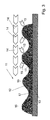
- FIG. 3 shows a sketch of another device 11 according to the invention for catching or retaining brake dust, in which a porous structure 12 is used.
- the open-pore structure 12 is in turn attached to the housing wall 13 of a brake unit, in the case shown here by gluing, wherein, as in the case of the magnetic strip of the previous embodiment, of course, alternatively or supplementary other mounting options can be provided.
- the rotation of the brake disk of the brake unit results in an air flow, which is indicated by the arrows 14 and which ensures that brake wear, which is transported with the flowing air, even reaches the area of the collecting device 11.
- the air flow generated by the brake disk rotation flows through the device 11, wherein due to the specific structuring on the air flow facing outer surface of the device 11 with elevations 16 and valleys 17, as indicated here by the arrows 15, promotion of the entry of brake abrasion is effected which is based on turbulences at a total low flow resistance of the device 11.
- the device 11 shown here has a porous structure 12 in which the pore size does not depend on the distance from the housing wall 13.
- the pore size of a corresponding catching structure increases from the surface facing the housing wall to the interior of the brake. This may possibly lead to a more effective collection of the brake dust.
- porous structure itself is made magnetic, optionally with the aid of fillers or additives and the like, or in which a device for catching and retaining brake wear in addition to porous agents in addition Magnets or in which areas based on one of the two principles of action alternate with each other.
Abstract
Description
Die Erfindung betrifft eine Vorrichtung zum Auffangen und/oder Zurückhalten von Bremsabrieb einer Bremseinheit sowie eine entsprechende Bremseinheit und ein entsprechendes Verfahren.The invention relates to a device for catching and / or retaining brake wear of a brake unit as well as a corresponding brake unit and a corresponding method.
Beim Bremsvorgang mit Bremseinheiten, bei denen die Bremswirkung auf dem Aneinanderpressen bzw. -reiben verschiedener Materialien besteht, beispielsweise beim Bremsen mit Scheibenbremsen, entsteht ein Bremsabrieb bzw. Bremsstaub, der sich beispielsweise auf Funktionseinheiten der Bremse ablagern kann und unter Umständen Funktionsstörungen bzw. eine Verschmutzung der Bremse bewirkt bzw., sofern die Bremseinheit zur Umgebung offen ist, nach außen austreten kann und die Umgebung der Bremse verschmutzt. Beispielsweise ist es bei elektromagnetisch betätigten Scheibenbremsen möglich, dass Abrieb von der Bremse zwischen die bei diesen Bremsen vorhandene Ankerscheibe und den Topfmagneten gelangt. Dadurch können die Funktion der Bremse und insbesondere die Funktion eines Schalters beeinträchtigt werden, der häufig zur Rückmeldung des Schaltzustands in derartige Bremsen eingebaut ist.When braking with brake units in which the braking effect on the juxtaposition or driving of different materials, such as braking with disc brakes, creates a brake wear or brake dust, which can be deposited for example on functional units of the brake and may malfunction or contamination causes the brake or, if the brake unit is open to the environment, can escape to the outside and pollutes the environment of the brake. For example, in the case of electromagnetically actuated disc brakes, it is possible for abrasion from the brake to pass between the armature disk present in these brakes and the pot magnet. As a result, the function of the brake and in particular the function of a switch can be impaired, which is often installed for reporting the switching state in such brakes.
Im Kraftfahrzeugbereich gibt es bereits einige Druckschriften, die sich mit dem Auffangen von Bremsstaub bzw. Bremsabrieb beschäftigen. So ist es beispielsweise aus der
Gemäß der
Bei diesen ausschließlich aus dem Kraftfahrzeugbereich stammenden Vorrichtungen ist jedoch zu beachten, dass, beispielsweise bei Anlegen einer Spannung, entweder eine zusätzliche äußere Energiequelle, also eine Fremdenergie, erforderlich ist. Oder es besteht, z. B. bei der Verwendung von Schichtstrukturen bzw. üblichen Filtern, das Problem, dass es nur schwer gelingt, den Abrieb gleichzeitig wirksam in die Vorrichtung hineinzutragen und ihn dann dort möglichst zuverlässig zurückzuhalten. Wünschenswerterweise müsste also einerseits die Luft mit den Staubpartikeln optimal in die Vorrichtung einströmen können und die Staubpartikel dürften andererseits durch den Luftstrom auch nicht wieder hinausgetragen werden.In the case of these devices, which originate exclusively from the motor vehicle sector, however, it should be noted that, for example, when a voltage is applied, either an additional external energy source, that is to say a foreign energy, is required. Or it exists, for. As in the use of layered structures or conventional filters, the problem that it is difficult to carry out the abrasion simultaneously effective in the device and then hold back there as reliably as possible. Desirably, therefore, on the one hand, the air with the dust particles would have to be able to flow optimally into the device, and on the other hand, the dust particles would probably not be carried out again by the air flow.
Dementsprechend liegt der vorliegenden Erfindung die Aufgabe zugrunde, eine gegenüber dem Stand der Technik verbesserte Vorrichtung sowie eine entsprechende Bremseinheit und ein entsprechendes Verfahren anzugeben.Accordingly, it is the object of the present invention to provide a device which is improved over the prior art and a corresponding brake unit and a corresponding method.
Zur Lösung dieser Aufgabe ist eine Vorrichtung zum Auffangen und/oder Zurückhalten von Bremsabrieb einer Bremseinheit vorgesehen, die sich dadurch auszeichnet, dass die Vorrichtung mit wenigstens einer Magnetanordnung zum Auffangen und/oder Zurückhalten von, zumindest im Wesentlichen, magnetischem Bremsabrieb mittels Magnetkraft und/oder mit wenigstens einem eine zur Förderung des Eintrags von Bremsabrieb geeignete Strukturierung an wenigstens einer äußeren Oberfläche aufweisenden porösen Mittel ausgebildet ist.To solve this problem, a device for collecting and / or withholding brake wear of a brake unit is provided, which is characterized in that the device with at least one magnet arrangement for capturing and / or retention of, at least substantially, magnetic brake wear by magnetic force and / or With is formed at least one suitable for promoting the entry of brake wear structuring on at least one outer surface having porous means.
Die Erfindung, die beispielsweise oder auch vorrangig bei Industriebremsen, aber grundsätzlich auch bei Bremsen in anderen Bereichen angewandt werden kann, beruht somit auf zwei unterschiedlichen Wirkprinzipien, die alleine aber auch in Kombination miteinander zum Einsatz kommen können. Für Industriebremsen, bei denen selbstverständlich auch das Problem von Funktionsstörungen und Verschmutzungen besteht, sind Auffangvorrichtungen für Bremsstaub bisher nicht bekannt.The invention, which can be applied, for example, or primarily in industrial brakes, but in principle also in brakes in other areas, thus based on two different principles of action, but alone or in combination with each other can be used. For industrial brakes, where of course there is the problem of malfunction and contamination, catching devices for brake dust are not yet known.
Der Bremsabrieb, der im Rahmen der Erfindung sehr allgemein als beim Bremsvorgang entstehender Staub bzw. anderes durch den Bremsvorgang frei werdendes bzw. in die Umgebung abgegebenes Material zu verstehen ist, kann also einerseits magnetisch zurückgehalten bzw. aufgefangen werden, andererseits in einer geeigneten offenporigen Struktur bzw. einem porösen Mittel adsorbiert werden. Diese Struktur oder das Mittel weisen hierzu erfindungsgemäß eine besonders strukturierte bzw. spezifisch ausgebildete äußere Oberfläche auf, die den Eintrag von Bremsabrieb in die Struktur mit ihren Poren fördert.The brake wear, which in the context of the invention is very generally understood as dust generated during the braking process or other material released by the braking process or emitted into the environment, can therefore be magnetically retained or captured on the one hand, and in a suitable open-pore structure on the other hand or a porous agent are adsorbed. According to the invention, this structure or the means have a particularly structured or specifically designed outer surface which promotes the entry of brake abrasion into the structure with its pores.
Besonders vorteilhaft bei Verwendung des Magnetprinzips ist, dass hierzu keine Fremdenergie nötig ist, wie dies beispielsweise im Stand der Technik der Fall ist, wenn eine geeignete Spannung von außen angelegt wird. Permanentmagnete benötigen keine derartige äußere Energiequelle. Die Besonderheit beim erfindungsgemäßen Adsorptionsprinzip ist hingegen, dass nicht nur durch die poröse Strukturierung der Mittel eine zum Auffangen des Abriebs geeignete Innenstruktur vorgegeben ist, sondern auch eine geeignete Gestaltung der äußeren Oberfläche derart vorliegt, dass der Eintrag von Bremsabrieb gezielt gefördert bzw. verbessert wird.It is particularly advantageous when using the magnetic principle that for this purpose no external energy is necessary, as is the case for example in the prior art, when a suitable voltage is applied from the outside. Permanent magnets do not require such an external energy source. The peculiarity of the adsorption principle according to the invention, however, is that not only by the porous structuring of the means an internal structure suitable for capturing the abrasion is given, but also a suitable design of the outer surface is present such that the entry of brake abrasion is selectively promoted or improved.
Ein besonderer Punkt bei der vorliegenden Erfindung ist, wie bereits dargelegt wurde, dass diese erstmalig eine Auffangeinheit für Bremsabrieb im Kontext von Industriebremsen, also nicht nur bei Radbremsen bzw. Kraftfahrzeugbremsen, vorsieht. Mit einer derartigen Auffangeinheit kann eine Beschädigung der Bremseinheit als solcher oder auch eine unerwünschte Verschmutzung oder Schädigung von Bauteilen in der Umgebung einer Maschine mit einer solchen Bremse verhindert werden.A special point in the present invention is, as already stated, that it provides for the first time a collecting unit for brake wear in the context of industrial brakes, ie not only in wheel brakes or motor vehicle brakes. With such a collecting unit damage to the brake unit as such or even an undesirable contamination or damage to components in the vicinity of a machine can be prevented with such a brake.
Erfindungsgemäß können wenigstens eine Magnetanordnung und/oder wenigstens ein poröses Mittel derart zur Förderung des Eintrags von Bremsabrieb strukturiert sein, dass zumindest die, bei Verwendung der Vorrichtung in einer Bremseinheit, einem inneren Bereich der Bremseinheit zugewandete äußere Oberfläche des porösen Mittels wellenartig, bei einer Magnetanordnung insbesondere mit Erhebungen sich abwechselnder Polarität, und/oder zur Wirbelbildung eines, insbesondere durch eine Rotation einer Bremsscheibe einer entsprechenden Bremseinheit entstehenden, Luftstroms in der Vorrichtung in wenigstens einem für den Eintrag von Bremsabrieb vorgesehenen Bereich der Vorrichtung ausgebildet ist.According to the invention, at least one magnet arrangement and / or at least one porous means may be structured to promote the entry of brake abrasion such that at least the outer surface of the porous means facing the inner region of the brake unit when using the device in a brake unit, like a wave, in a magnet arrangement in particular with elevations of alternating polarity, and / or for vortex formation of a, in particular caused by a rotation of a brake disc of a corresponding brake unit, air flow is formed in the device in at least one provided for the entry of brake abrasion portion of the device.
Erfindungsgemäß können somit nicht nur das oder die porösen Mittel, sondern ebenso bei Nutzung des Magnetprinzips der Magnet bzw. die Magnetanordnung an der äußeren Oberfläche strukturiert sein, um so den Bremsabriebeintrag zu verbessern. Eine Strukturierung, die sich besonders anbietet, ist eine grundsätzlich wellenartige Strukturierung. In diesem Fall wird, gegebenenfalls auf unterschiedliche Art und Weise, an der Grenzfläche z. B. zum Bereich der einströmenden Luft eine Strukturierung mit Erhebungen und Tälern ausgebildet, durch die es möglich ist, die Bremspartikel wirkungsvoll in die Auffangstruktur, also beispielsweise in das poröse bzw. an das magnetische Material hinein- bzw. heranzutragen. Durch die Strukturierung mit Tälern und Erhebungen entstehen strömungsberuhigte Zonen, in denen eine besonders gute Ablagerung des Materials möglich ist.Thus, according to the present invention, not only the porous agent (s) but also, when using the magnetic principle, the magnet or the magnet assembly may be structured on the outer surface so as to improve the brake abrasion input. A structuring that is particularly worthwhile is a fundamentally wavelike structuring. In this case, optionally in different ways, at the interface z. B. to the region of the incoming air structuring with elevations and valleys formed, by which it is possible to bring the Bremspartikel effective in the collection structure, so for example in the porous or to the magnetic material or bring. The structuring with valleys and elevations creates flow-calm zones, in which a particularly good deposition of the material is possible.
Die Auffangeinheit wird dann zweckmäßigerweise insgesamt von einem Luftstrom durchströmt, der beispielsweise durch eine Bremsscheibenrotation entsteht. Die somit in die Auffangvorrichtung eingeleitete Luft kann durch eine geeignete (äußere) Strukturierung des porösen Materials bzw. der Magnetanordnung zur Wirbelbildung angeregt werden, um so die Ablagerung von Abrieb zu verbessern. Bei einer Strukturierung der äußeren Oberfläche einer Magnetanordnung ist es besonders vorteilhaft, wenn die Erhebungen bzw. Berge eine abwechselnde Polarität aufweisen.The collecting unit is then expediently flowed through in total by an air flow, which arises, for example, by a brake disk rotation. The thus introduced into the collecting device air can be excited by a suitable (external) structuring of the porous material or the magnet arrangement for vortex formation, so as to improve the deposition of abrasion. In a structuring of the outer surface of a magnet arrangement, it is particularly advantageous if the elevations or mountains have an alternating polarity.
Die Vorrichtung und/oder wenigstens eine Magnetanordnung und/oder wenigstens ein poröses Mittel können derart ausgebildet sein, dass der Strömungswiderstand für ein Durchströmen der Vorrichtung durch einen, insbesondere durch eine Rotation einer Bremsscheibe einer entsprechenden Bremseinheit entstehenden, Luftstrom einen geringen und/oder optimalen Wert aufweist und/oder dass wenigstens eine Einström- und wenigstens eine Ausströmstruktur vorgesehen sind.The device and / or at least one magnet arrangement and / or at least one porous means may be designed such that the flow resistance for flowing through the device by a, in particular by a rotation of a brake disc of a corresponding brake unit, resulting air flow of a low and / or optimal value and / or that at least one inflow and at least one outflow structure are provided.
Die erfindungsgemäße Auffangvorrichtung wird also vorteilhafterweise so gestaltet, dass der Durchströmungswiderstand verringert bzw. gering ist. Ein derart optimierter Durchströmungswiderstand ergibt sich z. B. bei einer Struktur mit Erhebungen und Tälern durch rotierende Luftwalzen in den Tälern der Struktur bzw. ein queres Durchströmen der Berge. Weiterhin ist es von Vorteil, wenn bei der Vorrichtung, z. B: an einem Gehäuse, Einrichtungen bzw. Mittel sowohl zum Ermöglichen des Einströmens als auch des Ausströmens der Luft vorhanden sind, da nur bei einer Durchströmung ein Staubeintrag überhaupt möglich ist. Besteht hingegen keine geeignete Möglichkeit zum Herausströmen, strömt die Luft auch gar nicht erst ein und der Abrieb kann nicht gebunden werden. Somit wird bei der erfindungsgemäßen Auffangeinheit eine optimale Durchströmung, die es erst ermöglicht, dass Staub überhaupt eintreten kann, mit einer optimalen Ablagerung des aufzufangenden Bremsabriebs kombiniert.The collecting device according to the invention is thus advantageously designed so that the flow resistance is reduced or low. Such optimized flow resistance results z. B. in a structure with elevations and valleys by rotating air rollers in the valleys of the structure or a transverse flow through the mountains. Furthermore, it is advantageous if in the device, for. B: are provided on a housing, means or means both for allowing the influx and the outflow of air, since only with a flow of dust entry is possible. Conversely, if there is no suitable way to escape, the air does not even flow in and the abrasion can not be bound. Thus, in the case of the collecting unit according to the invention, an optimal throughflow, which only allows dust to be able to enter at all, is combined with an optimum deposition of the brake wear to be absorbed.
Bei Verwendung des magnetischen Wirkprinzips alleine bzw. in Kombination mit der Verwendung eines porösen Mittels kann wenigstens eine Magnetanordnung streifenförmig und/oder kunststoffgebunden ausgebildet sein, insbesondere mit mehreren nebeneinander angeordneten Magnetpolen.When using the magnetic principle of action alone or in combination with the use of a porous means, at least one magnet arrangement may be formed in a strip-shaped and / or plastic-bonded manner, in particular with a plurality of magnetic poles arranged next to one another.
Die Verwendung von streifenförmigen Magneten, insbesondere kunststoffgebundenen Streifen, bietet z. B. den Vorteil, dass die derart ausgebildeten Magnete in einfacher Art und Weise beispielsweise am inneren Umfang eines Bremsgehäuses befestigt werden können, ohne dass (größere) bauliche Veränderungen an den bisher verwendeten Bremsgehäusen erforderlich wären. Bei Streifenmagneten mit mehreren Polen muss nur ein einziges Element, nämlich der zusammenhängende Streifen, geeignet angeordnet werden, nicht eine Vielzahl einzelner (Pol-) Elemente.The use of strip-shaped magnets, in particular plastic-bonded strips, z. Example, the advantage that the magnets formed in this way can be attached in a simple manner, for example, on the inner circumference of a brake housing, without (major) structural changes to the previously used brake housings would be required. For multi-pole strip magnets, only a single element, namely the contiguous strip, must be properly arranged, not a plurality of individual (pole) elements.
Erfindungsgemäß können die Vorrichtung und/oder wenigstens eine Magnetanordnung, insbesondere eine streifenförmig ausgebildete Magnetanordnung, und/oder wenigstens ein poröses Mittel zur Befestigung mittels wenigstens eines Befestigungsmittels an einem inneren Bereich eines Gehäuses einer Bremseinheit ausgebildet sein, insbesondere zur form- und/oder kraft- und/oder stoffschlüssigen Befestigung.According to the invention, the device and / or at least one magnet arrangement, in particular a strip-shaped magnet arrangement, and / or at least one porous means for fastening can be formed by means of at least one fastening means on an inner area of a housing of a brake unit, in particular for positive and / or positive force. and / or cohesive attachment.
In diesem Fall werden z. B. die Magnetanordnung bzw. das poröse Mittel direkt in einem geeigneten Bereich der Bremseinheit, von der Staub aufgefangen werden soll, angebracht, wobei unterschiedliche Befestigungsmöglichkeiten alleine oder auch in Kombination miteinander verwendet werden können, beispielsweise Nieten, Klemmen oder ein Einspreizen oder Kleben des entsprechenden Abriebauffangmaterials, an dem hierzu geeignete Befestigungsmittel vorgesehen sein können. Selbstverständlich ist es ebenso denkbar, dass nicht die Magnetanordnung bzw. dass eine oder die mehreren porösen Mittel direkt an Bestandteilen der Bremseinheit befestigt bzw. montiert werden, sondern dass z. B. ein separates Gehäuse für die Auffangvorrichtung vorgesehen ist, das seinerseits befestigt wird, so dass gegebenenfalls die Magnetanordnung nur indirekt mit der Bremseinheit verbunden ist. Die Wahl der Befestigungsmittel hängt dabei unter anderem von den Belastungen ab, die im Betrieb der Bremse bzw. der Anlage oder Maschine, der die Bremse zugeordnet ist, auftreten. Weist die Bremse ein geschlossenes Gehäuse auf, so bietet sich eine Befestigung am inneren Gehäuseumfang an, beispielsweise durch Clippen, Ankleben und/oder Anschrauben oder dergleichen.In this case, z. B. the magnet assembly or the porous means directly in a suitable area of the brake unit to be collected from the dust, attached, with different mounting options alone or in combination can be used, for example, rivets, terminals or a spreading or gluing of the corresponding Abriebauffangmaterials on which suitable fastening means may be provided for this purpose. Of course, it is also conceivable that not the magnet assembly or that one or more porous means are attached or mounted directly on components of the brake unit, but that z. B. a separate housing for the Collection device is provided, which in turn is attached, so that optionally the magnet assembly is only indirectly connected to the brake unit. The choice of fasteners depends inter alia on the loads that occur during operation of the brake or the system or machine that is assigned to the brake. If the brake has a closed housing, an attachment on the inner circumference of the housing offers itself, for example by clipping, gluing and / or screwing on or the like.
Wird eine Bremseinheit mit einem geschlossenen Gehäuse mit der erfindungsgemäßen Auffangeinheit versehen, so bietet dies gegenüber dem Ansatz, einfach am Gehäuse Durchbrüche vorzusehen, aus denen der Staub austreten kann, den Vorteil, dass die Bremse in der so genannten "International-Protection-Klassifizierung" einer höheren Schutzklasse genügen kann und zudem die Verschmutzung der Umgebung der Bremse mit dem staubförmigen Abrieb vermieden wird.If a brake unit with a closed housing is provided with the collecting unit according to the invention, this offers the advantage over the approach of simply providing apertures on the housing from which the dust can escape, the advantage being that the brake is called the "International Protection Classification". a higher protection class can be sufficient and also the pollution of the environment of the brake is avoided with the dust-like abrasion.
Wenigstens eine Magnetanordnung und/oder wenigstens ein poröses Mittel und/oder ein Befestigungsmittel und/oder eine Befestigung der Vorrichtung und/oder einer Magnetanordnung und/oder eines porösen Mittels am Gehäuse einer Bremseinheit können temperatur- und/oder wärmebeständig ausgebildet sein, insbesondere für Temperaturen über 80°C.At least one magnet arrangement and / or at least one porous means and / or attachment means and / or attachment of the device and / or a magnet assembly and / or a porous means to the housing of a brake unit may be formed temperature and / or heat resistant, especially for temperatures over 80 ° C.
Die gegebenenfalls unterschiedlichen Befestigungsmittel bzw. Befestigungen für die Vorrichtung insgesamt, die Magnetanordnung bzw. ein oder mehrere poröse Mittel am Gehäuse können also, vorzugsweise alle, eine gewisse Temperaturbeständigkeit aufweisen, die bei üblichen Anwendungen bei Bremseinheiten typischerweise einen Temperaturbereich im Bereich von bzw. von über 80°C erfassen sollte. Gegebenenfalls kann es ausreichend sein, wenn nicht die Magnetanordnung bzw. das oder die porösen Mittel in ihrer Gesamtheit diese hohe Temperaturbeständigkeit aufweisen, sondern lediglich ein oder mehrere besonders exponierte Befestigungsmittel für einen Temperaturbereich von z. B. deutlich über 80°C geeignet sind. Dies hängt vom konkreten Anwendungsfall der Vorrichtung ab. Meist sind die an der Gehäusewandung von Bremseinheiten auftretenden Temperaturen recht hoch.The optionally different fastening means or fasteners for the device as a whole, the magnet arrangement or one or more porous means on the housing can therefore, preferably all, have a certain temperature resistance, which typically has a temperature range in the range of from or above about 80 ° C should capture. Optionally, it may be sufficient if not the magnet assembly or the porous means in their entirety have this high temperature resistance, but only one or more particularly exposed fasteners for a temperature range of z. B. well above 80 ° C are suitable. This depends on the specific application of the device. Most of the temperatures occurring at the housing wall of brake units are quite high.
Wenigstens ein poröses Mittel kann zum Auffangen und/oder Zurückhalten von Bremsabrieb durch Adsorptionskräfte ausgebildet sein, insbesondere durch Van-der-Waals-Kräfte. Van-der-Waals-Kräfte sind nichtkovalente Wechselwirkungen zwischen Atomen bzw. Molekülen. Bei einem Adsorptionsvorgang, der vom Vorgang der Absorption zu unterscheiden ist, werden Stoffe bzw. Materialien an der Oberfläche eines Festkörpers, hier also in den Öffnungen der porösen Struktur, und somit an der Grenzfläche zwischen zwei Phasen abgelagert. Der Bremsabrieb bleibt aufgrund der Adsorptionskräfte an der Oberfläche des porösen Mittels haften. Es kommt zu einer Anreicherung und somit zu einem Auffangen des Staubs in der Vorrichtung.At least one porous means may be designed to trap and / or restrain brake wear by adsorption forces, in particular Van der Waals forces. Van der Waals forces are noncovalent interactions between atoms or molecules. In an adsorption process, which is to be distinguished from the process of absorption, substances or materials are deposited on the surface of a solid, in this case in the openings of the porous structure, and thus at the interface between two phases. The brake wear remains adhering to the surface of the porous agent due to the adsorption forces. It comes to an accumulation and thus to a catching of the dust in the device.
Wenigstens ein poröses Mittel kann bei Verwendung der Vorrichtung in einer Bremseinheit mit einer, zumindest im Wesentlichen, in Richtung auf einen inneren Bereich der Bremseinheit zunehmenden Porengröße ausgebildet sein.At least one porous means may be formed when using the device in a brake unit with a, at least substantially, increasing in the direction of an inner region of the brake unit pore size.
Eine derart unterschiedliche Porengröße der Struktur, wobei die Größe der Poren nicht unbedingt streng in einer bestimmte Richtung zu- oder abnehmen muss, ermöglicht beispielsweise über eine wellenartige Strukturierung an der äußeren Oberfläche hinaus eine weitere Verbesserung der Ablagerung des Bremsabriebs im Inneren. Die Ablagerung des Staubs in der Auffangvorrichtung wird somit z. B. durch eine geringere Strömungsgeschwindigkeit in bestimmten Bereichen, durch einen verringerten Durchströmungswiderstand insgesamt und des Weiteren durch die Ausnutzung von Adsorptionskräften zwischen den Staubpartikeln und der porösen Struktur gefördert und zudem durch die geeignete Wahl der Porengröße weiter optimiert.Such a different pore size of the structure, wherein the size of the pores does not necessarily have to increase or decrease strictly in a certain direction allows, for example via a wave-like structuring on the outer surface, a further improvement of the deposition of the brake wear inside. The deposition of dust in the collecting device is thus z. B. promoted by a lower flow velocity in certain areas, by a reduced flow resistance in total and further by the use of adsorption between the dust particles and the porous structure and further optimized by the appropriate choice of pore size.
Des Weiteren kann wenigstens ein poröses Mittel aus wenigstens einem organischen und/oder wenigstens einem anorganischen Material ausgebildet sein, insbesondere aus Glas und/oder einem Material auf Silikatbasis und/oder einem Metall und/oder einem Polymer, beispielsweise einem Epoxid-und/oder einem Polyester- und/oder einem Phenolharz.Furthermore, at least one porous agent can be formed from at least one organic and / or at least one inorganic material, in particular glass and / or a silicate-based material and / or a metal and / or a polymer, for example an epoxide and / or one Polyester and / or a phenolic resin.
Grundsätzlich kommen somit unterschiedliche Materialien für die poröse Struktur in Frage, wobei, ebenso wie bei den Magnetanordnungen, die Materialwahl so erfolgen sollte, dass gegebenenfalls den z. B. an einer Gehäusewandung einer Bremseinheit auftretenden Temperaturen zuverlässig widerstanden werden kann. Unter Umständen können auch verschiedene poröse Mittel, teilweise aus organischen, teilweise aus anorganischen Materialien, verwendet werden. Entscheidend ist letztlich, dass sich eine geeignete offenporige Struktur herstellen lässt und dass der Werkstoff die benötigte Wärmebeständigkeit, meist von über 80°C, aufweist. Dabei können die porösen Mittel bzw. das poröse Mittel einer derartigen Auffangvorrichtung aus einem einzigen Werkstoff bestehen, z. B. aus Glas, bzw. es können Mischungen oder abwechselnd angeordnete Materialien verwendet werden, beispielsweise derart, dass eine unterschiedliche Porengröße durch unterschiedliche Materialien realisiert wird.In principle, therefore, different materials for the porous structure in question, where, as with the magnet arrangements, the choice of material should be such that optionally the z. B. occurring at a housing wall of a brake unit temperatures can be reliably resisted. It is also possible to use various porous agents, partly of organic, partly of inorganic materials. Ultimately, it is crucial that a suitable open-pore structure can be produced and that the material has the required heat resistance, usually above 80 ° C. The porous means or the porous means of such a collecting device may consist of a single material, for. As glass, or mixtures or alternately arranged materials may be used, for example, such that a different pore size is realized by different materials.
Wenigstens ein poröses Mittel kann, zumindest teilweise, als offenporiger Schaum und/oder als Vlies und/oder als Gewebe und/oder als Watte und/oder auf Faserbasis ausgebildet sein und/oder die Vorrichtung kann wenigstens ein Gitter und/oder Lochblech und/oder Gewebe als Begrenzung, insbesondere in Richtung auf einen inneren Bereich einer Bremseinheit, aufweisen.At least one porous agent may be formed, at least in part, as an open-cell foam and / or as a non-woven and / or as a woven fabric and / or as a cotton wool and / or fiber-based and / or the device may comprise at least one grid and / or perforated plate and / or Have tissue as a limitation, in particular in the direction of an inner region of a brake unit.
Eine Begrenzung der Auffangeinheit zum Bremseninneren hin bietet sich insbesondere bei Verwendung eines wenig formbeständigen Materials wie Watte an, in welchem Fall dann eine feste Abgrenzung gegenüber der Umgebung beispielsweise durch ein Gitter bzw. dergleichen geschaffen werden kann. Selbstverständlich kann beispielsweise ein Schaum in Kombination mit einem Gewebe oder einer Watte verwendet werden bzw. die poröse Struktur kann einen einheitlichen Aufbau aufweisen. Aus den genannten Materialien können z. B. geeignete Fasern hergestellt werden, die in der Auffangvorrichtung nach Bedarf angeordnet bzw. geeignet miteinander kombiniert werden.A limitation of the collecting unit to the brake inside out offers itself in particular when using a less dimensionally stable material such as cotton, in which case then a firm demarcation from the environment For example, by a grid or the like can be created. Of course, for example, a foam may be used in combination with a fabric or a cotton wool or the porous structure may have a uniform structure. From the materials mentioned z. B. suitable fibers are produced, which are arranged in the collecting device as needed or suitably combined with each other.
Die Vorrichtung kann mit wenigstens einer im Wechsel mit wenigstens einem porösen Mittel angeordneten Magnetanordnung, insbesondere mit einer Magnetanordnung an einem inneren Bereich eines Gehäuses und wenigstens einem sich zum inneren Bereich einer Bremseinheit anschließenden porösen Mittel, ausgebildet sein und/oder es kann wenigstens ein poröses Mittel, insbesondere mittels wenigstens eines Füllstoffes und/oder durch geeignete Materialwahl, eine Magnetanordnung darstellen.The device may be formed with at least one arranged in alternation with at least one porous means magnet assembly, in particular with a magnet assembly on an inner portion of a housing and at least one subsequent to the inner portion of a brake unit porous means, and / or it may at least one porous means , In particular by means of at least one filler and / or by suitable choice of material represent a magnet assembly.
Es gibt somit unterschiedliche Möglichkeiten einer Kombination der zwei grundlegend verschiedenen Wirkprinzipien, nämlich des Auffangens des Bremsabriebs durch Magnetkraft und des Auffangens in einer porösen Struktur.There are thus different possibilities for a combination of the two fundamentally different principles of action, namely the interception of the brake abrasion by magnetic force and the interception in a porous structure.
Einerseits kann der in einer Bremse verfügbare Bauraum abwechselnd mit Auffangstrukturen nach den unterschiedlichen Prinzipien bestückt werden, andererseits kann beispielsweise die poröse Struktur durch eine entsprechende Materialwahl oder mit Füllstoffen so ausgeführt werden, dass sie letztlich selbst als Permanentmagnet wirksam ist und entsprechend mit abwechselnder Polarität aufmagnetisiert wird. Gegebenenfalls kann eine geeignete permanentmagnetische Struktur zwischen der porösen Struktur und der Gehäuseinnenwand einer Bremse so angebracht werden, dass an der der Bremsinnenseite zugewandten Oberfläche der porösen Struktur noch eine zum Auffangen des Bremsabriebs bzw. zu dessen Bindung ausreichende magnetische Feldstärke vorhanden ist, insbesondere im Bereich von bzw. mehr als 1000 A/m (Ampere pro Meter).On the one hand, the space available in a brake can alternately be equipped with collecting structures according to the different principles, on the other hand, for example, the porous structure by an appropriate choice of materials or with fillers are designed so that it is ultimately effective even as a permanent magnet and is magnetized accordingly with alternating polarity , Optionally, a suitable permanent magnetic structure between the porous structure and the housing inner wall of a brake can be mounted so that on the brake inner side facing surface of the porous structure is still sufficient for capturing the brake wear or its binding magnetic field strength, especially in the range of or more than 1000 A / m (amperes per meter).
Auch bei einer Kombination beider Prinzipien sowie bei einer Verwendung des Magnetprinzips allein bietet die bereits beschriebene Möglichkeit einer wellenförmigen Ausführung der äußeren Oberfläche den Vorteil, dass sich der Staub einfacher (magnetisch) fixieren lässt, da durch die Wellenform strömungsberuhigte Zonen geschaffen werden. Durch eine unterschiedliche Polarität jeweils benachbarter Erhebungen wird in den Einbuchtungen zwischen den Erhebungen eine vergleichsweise hohe magnetische Feldstärke erzielt.Even with a combination of both principles and when using the magnetic principle alone, the already described possibility of a wavy design of the outer surface offers the advantage that the dust can be fixed more easily (magnetically), since flow-calmed zones are created by the wave form. By a different polarity respectively adjacent surveys a comparatively high magnetic field strength is achieved in the indentations between the surveys.
Darüber hinaus betrifft die Erfindung eine Bremseinheit, ausgebildet mit einer Vorrichtung zum Auffangen und/oder Zurückhalten von Bremsabrieb einer Bremseinheit, die sich dadurch auszeichnet, dass die Vorrichtung mit wenigstens einer Magnetanordnung zum Auffangen und/oder Zurückhalten von, zumindest im Wesentlichen, magnetischem Bremsabrieb mittels Magnetkraft und/oder mit wenigstens einem eine zur Förderung des Eintrags von Bremsabrieb geeignete Strukturierung an wenigstens einer äußeren Oberfläche aufweisenden porösen Mittel ausgebildet ist, insbesondere mit einer Vorrichtung wie im Vorstehenden geschildert.Moreover, the invention relates to a brake unit, formed with a device for intercepting and / or retaining brake wear of a brake unit, which is characterized in that the device with at least one magnet arrangement for intercepting and / or retention of, at least substantially, magnetic brake wear means Magnetic force and / or with at least one suitable for promoting the entry of brake wear structuring on at least one outer surface having porous means is formed, in particular with a device as described above.
Die Bremse weist somit eine separate bzw. in die Bremse integrierte Auffangvorrichtung für Bremsstaub auf, die auf einem magnetischen Wirkprinzip bzw. einem Wirkprinzip mit einer porösen Struktur mit einer geeigneten, den Eintrag des Bremsabriebs fördernden (äußeren) Oberflächenstrukturierung bzw. einer Kombination dieser beiden Wirkprinzipien basiert.The brake thus has a separate or integrated into the brake collecting device for brake dust on a magnetic principle or an active principle with a porous structure with a suitable, the entry of the brake wear promoting (outer) surface structuring or a combination of these two principles of action based.
Bei der Bremseinheit kann es sich um eine Industriebremseinheit, insbesondere eine Haltebremseinheit und/oder eine Sicherheitsbremseinheit und/oder einer Arbeitsbremse, oder eine Bremseinheit für Fahrzeuge und/oder eine Scheibenbremseinheit handeln. Die Realisierung mit der beschriebenen Auffangvorrichtung kann somit in unterschiedlichen Bremsanwendungsbereichen vorgenommen werden, insbesondere auch bei Industriebremsen, beispielsweise als Haltebremse oder reine Sicherheitsbremse mit Notstoppfunktion. Daneben ist eine Ausführung der Auffangeinheit für Arbeitsbremsen denkbar, bei denen in der Regel gegenüber Halte- und Sicherheitsbremsen aufgrund des höheren Verschleißweges mehr Abrieb anfällt.The brake unit may be an industrial brake unit, in particular a holding brake unit and / or a safety brake unit and / or a service brake, or a brake unit for vehicles and / or a disc brake unit. The realization with the described collecting device can thus in different brake application areas be made, especially in industrial brakes, for example as a holding brake or pure safety brake with emergency stop function. In addition, an embodiment of the collecting unit for work brakes is conceivable in which usually more wear occurs over holding and safety brakes due to the higher wear path.
Die Vorrichtung zum Auffangen und/oder Zurückhalten von Bremsabrieb kann bei der Bremseinheit, zumindest im Wesentlichen, in einem Bereich radial um eine Bremsscheibe der Bremseinheit angeordnet sein und/oder die Bremseinheit kann, zumindest über wenigstens ein Winkelsegment in einem Bereich radial um eine Bremsscheibe, einen ein- oder mehrteiligen Raum zur Aufnahme der Vorrichtung zum Auffangen und/oder Zurückhalten von Bremsabrieb aufweisen.The device for intercepting and / or retaining brake abrasion can be arranged at the brake unit, at least substantially, in a region radially around a brake disk of the brake unit and / or the brake unit can, at least over at least one angular segment in a region radially around a brake disk, have a one or more parts space for receiving the device for collecting and / or retaining brake wear.
Die Art des Aufsammelns des Staubs radial um die Bremsscheibe bietet sich in dem Fall an, dass keine Sattelbremse vorliegt, sondern der Abrieb einer Bremse mit auf dem ganzen Umfang anliegenden Bremsbelägen aufgefangen werden soll. Bremseinheiten sind in der Regel bereits so ausgeführt, dass sich rings um die Bremsscheibe entsprechende freie Räume befinden, die als Bauräume für die Vorrichtung zum Auffangen des Bremsabriebs genutzt werden können, bzw. es ist möglich, eine Bremse so auszuführen, dass zumindest über gewisse Winkelsegmente radial ein derartiger ein- bzw. mehrteiliger Raum geschaffen wird, der für die erfindungsgemäße Auffangeinheit benutzt werden kann.The manner of collecting the dust radially around the brake disc is appropriate in the event that there is no caliper brake, but the abrasion of a brake is to be collected with applied to the entire circumference brake pads. Brake units are usually already carried out so that there are corresponding free spaces around the brake disc, which can be used as space for the device for collecting the brake wear, or it is possible to perform a brake so that at least over certain angle segments radially such a one- or multi-part space is created, which can be used for the collecting unit according to the invention.
Bei der erfindungsgemäßen Bremseinheit können wenigstens ein Reibbelag und/oder wenigstens ein Reibpartner der Bremseinheit, zumindest im Wesentlichen, aus wenigstens einem ferromagnetischen oder ferrimagnetischen Material bestehen, insbesondere aus Stahl und/oder Gusseisen und/oder aufgrund entsprechender Zuschläge.In the brake unit according to the invention, at least one friction lining and / or at least one friction partner of the brake unit can consist, at least essentially, of at least one ferromagnetic or ferrimagnetic material, in particular of steel and / or cast iron and / or due to corresponding additions.
Sehr oft handelt es sich bei den Reibpartnern für den Reibbelag in herkömmlichen Bremsen bereits um ferromagnetische Werkstoffe wie Stahl oder Gusseisen. Auch sind einige Reibbeläge ferro- oder zumindest ferrimagnetisch, meist bedingt durch entsprechende Zuschläge. Aber auch in dem Fall, dass die Reibbeläge selbst unmagnetisch sind, ergibt sich bei ferromagnetischen Reibpartnern ein insgesamt magnetischer Bremsabrieb, weil sich die unmagnetischen Partikel des Abriebs und die ferromagnetischen Partikel des Reibpartners aneinander anlagern, so dass der Abrieb insgesamt an einer geeigneten Dauermagnetanordnung angelagert werden kann. Durch das Binden des Abreibs wird verhindert, dass sich dieser frei im Inneren des Bremsengehäuses verteilen kann und so beispielsweise die Bremsenfunktion negativ beeinträchtigt.Very often, the friction partners for the friction lining in conventional brakes are already ferromagnetic materials such as steel or cast iron. Also, some friction linings are ferro- or at least ferrimagnetic, usually due to appropriate surcharges. But even in the case that the friction linings themselves are non-magnetic, resulting in ferromagnetic Reibpartnern a total magnetic brake wear, because the non-magnetic particles of the abrasion and the ferromagnetic particles of the friction partner abut each other, so that the total abrasion are attached to a suitable permanent magnet assembly can. The binding of the Abreibs is prevented that this can freely distribute in the interior of the brake housing and so for example, the brake function adversely affected.
Die Bremseinheit kann ein geschlossenes Gehäuse aufweisen, insbesondere ein zumindest im Wesentlichen oder vollständig geschlossenes Gehäuse.The brake unit may have a closed housing, in particular an at least substantially or completely closed housing.
Gerade im Fall von Bremsen mit einem geschlossenen Gehäuse kann es, um auf Dauer ein zuverlässiges Funktionieren in der Bremse zu gewährleisten, von Vorteil sein, den Bremsabrieb möglichst vollständig aufzufangen, damit es nicht zu einer Verschmutzung funktionswichtiger Bestandteile und Komponenten der Bremse kommt. Andererseits kann es auch bei einem Bremsgehäuse mit Öffnungen bzw. Bremsen ohne Gehäuse von Vorteil sein, den Bremsabrieb aufzufangen, schon um eine Verschmutzung der Umgebung zu verhindern. Die Verwendung eines geschlossenen Gehäuses in Kombination mit einer erfindungsgemäßen Auffangvorrichtung kann außerdem dazu führen, dass die Bremseinheit insgesamt höheren Schutz- bzw. Sicherheitsanforderungen genügt.Especially in the case of brakes with a closed housing, to ensure reliable operation in the brake over time, it may be advantageous to absorb the brake wear as completely as possible, so that it does not lead to contamination of functionally important components and components of the brake. On the other hand, it may also be advantageous in a brake housing with openings or brakes without housing to absorb the brake wear, even to prevent contamination of the environment. The use of a closed housing in combination with a collecting device according to the invention can also lead to the fact that the braking unit as a whole satisfies higher protection or safety requirements.
Bei Vorliegen eines Gehäuses können die oder eine Vorrichtung bzw. wenigstens eine Magnetanordnung, insbesondere eine streifenförmig ausgebildete Magnetanordnung, und/oder wenigstens ein poröses Mittel an einem inneren Bereich des Gehäuses der Bremseinheit, vorrangig am inneren Umfang, befestigt sein. Die Magnetanordnung bzw. das oder die porösen Mittel der Auffangvorrichtung für den Bremsantrieb können also vorteilhafterweise geeignet an der Gehäusewandung befestigt werden, wobei sie hierzu so ausgeführt sein müssen, dass sie den dort auftretenden Temperaturen zuverlässig widerstehen. Die Befestigung am Gehäuse kann, wie bereits im Zusammenhang mit der Vorrichtung geschildert wurde, form-, kraft- und/oder stoffschlüssig ausgebildet sein. Insbesondere bietet sich eine Befestigung durch Nieten, Schrauben bzw. Klemmen und/oder Einspreizen und/oder Kleben an.In the presence of a housing, the or a device or at least one magnet arrangement, in particular a strip-shaped formed magnet assembly, and / or at least one porous means at an inner region of the housing of the brake unit, primarily on the inner circumference, be attached. The magnet arrangement or the porous means of the collecting device for the brake drive can thus be advantageously suitably attached to the housing wall, wherein they must be designed so that they reliably withstand the temperatures occurring there. The attachment to the housing, as has already been described in connection with the device, form, force and / or cohesively formed. In particular, a fastening by rivets, screws or clamps and / or spreading and / or gluing offers.
Wenigstens eine Magnetanordnung und/oder wenigstens ein poröses Mittel und/oder ein Befestigungsmittel und/oder eine Befestigung der Vorrichtung und/oder einer Magnetanordnung und/oder eines porösen Mittels am Gehäuse der Bremseinheit, also ein oder mehrere bzw. alle Befestigungsmittel und/oder Befestigungen, die eine oder die mehreren Vorrichtungen und gegebenenfalls bestimmte Funktionsteile der Vorrichtung, können temperatur-und/oder wärmebeständig ausgebildet sein, insbesondere für Temperaturen über 80°C, mit denen oft an den Gehäusen bzw. Gehäusewandungen von Industriebremsen bzw. bei Bremsen in anderen Bereichen zu rechnen ist.At least one magnet arrangement and / or at least one porous means and / or attachment means and / or attachment of the device and / or a magnet assembly and / or a porous means on the housing of the brake unit, so one or more or all fastening means and / or fasteners , the one or more devices and possibly certain functional parts of the device, may be temperature and / or heat resistant, especially for temperatures above 80 ° C, often with the housings of industrial brakes or brakes in other areas is to be expected.
Dabei ist die hier angegebene Temperatur von 80°C bzw. die Wärmebeständigkeit für Temperaturen über 80°C lediglich beispielhaft zu verstehen. Selbstverständlich können je nach Bremseinheit bzw. bei speziellen Bremsen höhere oder auch geringere Anforderungen hinsichtlich der Temperaturbeständigkeit bestehen, für die dann die Auffangvorrichtungen entsprechend auszurichten sind.The temperature specified here of 80 ° C. or the heat resistance for temperatures above 80 ° C. is only an example. Of course, depending on the brake unit or special brakes higher or lower requirements in terms of temperature resistance, for which then the collecting devices are to be aligned accordingly.
Die eine oder die mehreren Vorrichtungen zum Auffangen und/oder Zurückhalten von Bremsabrieb bei der Bremseinheit können mit wenigstens einer im Wechsel mit wenigstens einem porösen Mittel angeordneten Magnetanordnung, insbesondere mit einer Magnetanordnung an einem inneren Bereich eines Gehäuses und wenigstens einem sich zum inneren Bereich der Bremseinheit anschließenden porösen Mittel, ausgebildet sein und/oder es kann wenigstens ein poröses Mittel, insbesondere mittels wenigstens eines Füllstoffes und/oder durch geeignete Materialwahl, eine Magnetanordnung darstellen.The one or more devices for capturing and / or restraining brake wear in the brake unit may be arranged with at least one alternating with at least one porous means Magnetic arrangement, in particular with a magnet arrangement on an inner region of a housing and at least one subsequent to the inner region of the brake unit porous means, be formed and / or it may at least one porous agent, in particular by means of at least one filler and / or by suitable choice of material, a Represent magnet arrangement.
Es gibt somit unterschiedliche Möglichkeiten, die Auffangvorrichtung bzw. die Auffangvorrichtungen der Bremseinheit so auszuführen, dass darin die unterschiedlichen Wirkprinzipien, einerseits der Verwendung von Magnetkraft zum Binden des Staubs, andererseits des Verwendens einer porösen Struktur mit einer geeigneten äußeren Oberfläche, kombiniert sind.There are thus different possibilities for carrying out the catching device or catching devices of the brake unit in such a way that it combines the different active principles, on the one hand the use of magnetic force for binding the dust, and on the other hand the use of a porous structure with a suitable outer surface.
Dabei ist gegebenenfalls zu beachten, dass für eine effektive Nutzung des Magnetprinzips an der Bremseninnenseite eine noch ausreichende magnetische Feldstärke gegeben ist.It should be noted, if necessary, that for an effective use of the magnetic principle on the inside of the brake a sufficient magnetic field strength is given.
Außerdem betrifft die Erfindung ein Verfahren zum Auffangen und/oder Zurückhalten von Bremsabrieb einer Bremseinheit, insbesondere einer Industriebremseinheit und/oder einer Bremseinheit wie im Vorstehenden geschildert und/oder mittels wenigstens einer Vorrichtung, wie sie eingangs beschrieben wurde, bei welchem Verfahren mittels wenigstens einer Magnetanordnung, zumindest im Wesentlichen, magnetischer Bremsabrieb mittels Magnetkraft und/oder bei welchem Bremsabrieb mittels wenigstens eines eine zur Förderung des Eintrags von Bremsabrieb geeignete Strukturierung an wenigstens einer äußeren Oberfläche aufweisenden porösen Mittels aufgefangen und/oder zurückgehalten wird.Moreover, the invention relates to a method for intercepting and / or restraining brake wear of a brake unit, in particular an industrial brake unit and / or a brake unit as described above and / or by means of at least one device, as described in the introduction, in which method by means of at least one magnet arrangement , at least substantially, magnetic brake wear by means of magnetic force and / or in which brake wear by means of at least one suitable for promoting the entry of brake wear structuring on at least one outer surface having porous means and / or retained.
Das Verfahren ist also ein Verfahren zum Binden bzw. Fixieren von Bremsstaub, bei dem (bei insgesamt magnetischem Bremsabrieb) ein magnetisches Bindungsprinzip und/oder (z. B. bei teilweise nicht magnetischem Abrieb) ein Prinzip der Staubbindung mittels eines porösen Mittels, das eine geeignete Strukturierung einer äußeren Oberfläche aufweist, alleine bzw. in Kombination miteinander zum Einsatz kommen.The method is thus a method for binding or fixing brake dust, in which (in the case of total magnetic brake abrasion) a magnetic binding principle and / or (eg in the case of partially non-magnetic abrasion) is a principle of dust binding by means of a porous agent, which is a has suitable structuring of an outer surface, used alone or in combination with each other.
Weitere Vorteile, Merkmale und Einzelheiten der Erfindung ergeben sich anhand der folgenden Ausführungsbeispiele sowie aus den Zeichnungen. Dabei zeigen:
-
Figur 1 eine Darstellung einer erfindungsgemäßen Bremseinheit, -
Figur 2 -
Figur 3
-
FIG. 1 a representation of a brake unit according to the invention, -
FIG. 2 a sketch of a device according to the invention for collecting and / or retaining brake wear on the housing of a brake unit by magnetic force and -
FIG. 3 a sketch of another device according to the invention with a porous structure.
In der
Im vorliegenden Ausführungsbeispiel sind mehrere Bauräume 5 für Auffangvorrichtungen vorhanden, so dass ein insgesamt mehrteiliger Bereich vorliegt, in dem jeweils die Auffangeinheiten für den Bremsabrieb aufgenommen sind. Dabei können bei verschiedenen Bremseinheiten Auffangeinheiten unterschiedlicher Art in dem Sinne verwendet werden, dass sie entweder auf einem magnetischen Wirkprinzip oder ausschließlich auf dem Wirkprinzip der porösen Struktur basieren bzw. eine Kombination beider Wirkprinzipien vorsehen.In the present exemplary embodiment, a plurality of
In der
Im hier gezeigten Ausführungsbeispiel ist der Magnetstreifen 7 an der Gehäusewandung 8 angeklebt. In anderen Ausführungsbeispielen können aber ebenso andere Befestigungsarten wie Nieten, Klemmen bzw. Befestigen durch Einspreizen oder Schrauben oder auch eine Kombination unterschiedlicher Befestigungsarten zum Einsatz kommen.In the embodiment shown here, the
Auf dem Magnetstreifen 7 wechseln sich Pole unterschiedlicher Polarität ab, zwischen denen Feldlinien 9 verlaufen. Wie in der Skizze zu sehen ist, lagert sich der durch die über die Vorrichtung hinweg strömende Luft transportierte insgesamt magnetische Bremsabrieb 10 an Polen des Magnetstreifens 7 ab und wird so fixiert bzw. gebunden. Damit wird verhindert, dass sich der Bremsabrieb 10 frei im Inneren des Bremsgehäuses verteilen kann und so gegebenenfalls eine Schädigung der Funktion der Bremse herbeiführt.On the
Der Magnetstreifen 7 ist so ausgeführt, dass er und die entsprechende Klebbefestigung den an der Gehäusewandung 8 auftretenden Temperaturen von gegebenenfalls über 80°C zuverlässig widersteht.The
Die
Durch die Rotation der hier nicht gezeigten Bremsscheibe der Bremseinheit ergibt sich eine Luftströmung, die durch die Pfeile 14 angedeutet ist und die dafür sorgt, dass Bremsabrieb, der mit der strömenden Luft transportiert wird, überhaupt in den Bereich der Auffangvorrichtung 11 gelangt. Die durch die Bremsscheibenrotation erzeugte Luftströmung durchströmt die Vorrichtung 11, wobei aufgrund der spezifischen Strukturierung an der dem Luftstrom zugewandten äußeren Oberfläche der Vorrichtung 11 mit Erhebungen 16 sowie Tälern 17, wie hier durch die Pfeile 15 angedeutet, eine Förderung des Eintrags von Bremsabrieb bewirkt wird, die auf Verwirbelungen bei einem gleichzeitig insgesamt geringen Durchströmungswiderstand der Vorrichtung 11 beruht.The rotation of the brake disk of the brake unit, not shown here, results in an air flow, which is indicated by the
Die hier gezeigte Vorrichtung 11 weist eine poröse Struktur 12 auf, bei der die Porengröße nicht vom Abstand von der Gehäusewandung 13 abhängt. Ebenso ist es aber in anderen Ausführungsbeispielen denkbar, dass die Porengröße einer entsprechenden Auffangstruktur sich von der der Gehäusewandung zugewandten Oberfläche zu dem Inneren der Bremse hin vergrößert. Dies kann gegebenenfalls zu einem effektiveren Auffangen des Bremsstaubs führen.The
Daneben sind selbstverständlich Ausführungen denkbar, in denen die poröse Struktur selbst magnetisch ausgeführt ist, gegebenenfalls mit Hilfe von Füllstoffen bzw. Zusätzen und dergleichen, oder bei denen eine Vorrichtung zum Auffangen und Zurückhalten von Bremsabrieb neben porösen Mitteln zusätzlich Magnete aufweist bzw. bei denen sich Bereiche, die auf einem der beiden Wirkprinzipien basieren, miteinander abwechseln.In addition, of course, embodiments are conceivable in which the porous structure itself is made magnetic, optionally with the aid of fillers or additives and the like, or in which a device for catching and retaining brake wear in addition to porous agents in addition Magnets or in which areas based on one of the two principles of action alternate with each other.
- 11
- Bremseinheitbrake unit
- 22
- Bremsscheibebrake disc
- 33
- Gehäusecasing
- 44
- Durchgangpassage
- 55
- Bauraumspace
- 66
- Vorrichtung zum Auffangen und/oder Zurückhalten von BremsabriebDevice for catching and / or retaining brake abrasion
- 77
- Magnetstreifenmagnetic stripe
- 88th
- Gehäusewandunghousing
- 99
- Feldliniefield line
- 1010
- Bremsabriebbrake dust
- 1111
- Vorrichtung zum Auffangen bzw. Zurückhalten von BremsstaubDevice for catching or retaining brake dust
- 1212
- poröse Strukturporous structure
- 1313
- Gehäusewandunghousing
- 1414
- Luftströmungairflow
- 1515
- Pfeilarrow
- 1616
- Erhebungsurvey
- 1717
- Talvalley
Claims (15)
Priority Applications (1)
| Application Number | Priority Date | Filing Date | Title |
|---|---|---|---|
| EP08163370A EP2151596B1 (en) | 2008-07-31 | 2008-09-01 | Device for capturing and/or retaining brake dust of a braking unit and corresponding brake unit |
Applications Claiming Priority (2)
| Application Number | Priority Date | Filing Date | Title |
|---|---|---|---|
| EP08161543 | 2008-07-31 | ||
| EP08163370A EP2151596B1 (en) | 2008-07-31 | 2008-09-01 | Device for capturing and/or retaining brake dust of a braking unit and corresponding brake unit |
Publications (2)
| Publication Number | Publication Date |
|---|---|
| EP2151596A1 true EP2151596A1 (en) | 2010-02-10 |
| EP2151596B1 EP2151596B1 (en) | 2011-11-02 |
Family
ID=40275968
Family Applications (1)
| Application Number | Title | Priority Date | Filing Date |
|---|---|---|---|
| EP08163370A Active EP2151596B1 (en) | 2008-07-31 | 2008-09-01 | Device for capturing and/or retaining brake dust of a braking unit and corresponding brake unit |
Country Status (2)
| Country | Link |
|---|---|
| EP (1) | EP2151596B1 (en) |
| AT (1) | ATE531964T1 (en) |
Cited By (7)
| Publication number | Priority date | Publication date | Assignee | Title |
|---|---|---|---|---|
| WO2011034431A1 (en) * | 2009-09-18 | 2011-03-24 | Idlos B.V. | Brake pad assembly and method for collecting brake particles |
| US8926738B2 (en) | 2010-09-20 | 2015-01-06 | Idlos B.V. | Brake pad assembly and method for collecting brake particles |
| WO2019048374A1 (en) * | 2017-09-08 | 2019-03-14 | Mann+Hummel Gmbh | Brake dust particle filter and disc brake assembly comprising a brake dust particle filter |
| CN112219040A (en) * | 2018-05-22 | 2021-01-12 | 曼·胡默尔有限公司 | Brake dust particle filter and disc brake assembly with a brake dust particle filter |
| US11187288B2 (en) | 2019-07-31 | 2021-11-30 | Federal-Mogul Motorparts Llc | Vehicle brake component for collecting brake dust |
| DE102021202084A1 (en) | 2021-03-04 | 2022-09-08 | Psa Automobiles Sa | Wheel assembly for a motor vehicle |
| WO2023193988A1 (en) * | 2022-04-06 | 2023-10-12 | Psa Automobiles Sa | Brake disc for a vehicle |
Families Citing this family (2)
| Publication number | Priority date | Publication date | Assignee | Title |
|---|---|---|---|---|
| DE102021202604A1 (en) | 2021-03-17 | 2022-09-22 | Psa Automobiles Sa | Disk brake device for a motor vehicle |
| DE102021207985A1 (en) | 2021-07-23 | 2023-01-26 | Psa Automobiles Sa | Motor vehicle wheel assembly and wheel cover |
Citations (8)
| Publication number | Priority date | Publication date | Assignee | Title |
|---|---|---|---|---|
| US873532A (en) | 1906-04-02 | 1907-12-10 | Forsyth Brothers Company | Dust-collector. |
| US2988173A (en) | 1955-11-02 | 1961-06-13 | Joseph C Romine | Magnetic ferrous metal dust collector |
| DE3934422A1 (en) | 1988-10-25 | 1990-04-26 | Karl Boesch | DISC BRAKE FOR VEHICLE WHEELS |
| WO2004067985A1 (en) | 2003-01-27 | 2004-08-12 | Kabushiki Kaisha Yaskawa Denki | Electromagnetic brake and electric motor incorporating the electromagnetic brake |
| WO2004080740A1 (en) | 2003-03-12 | 2004-09-23 | 3K Technologies, Inc. | System and method for removing pollutants from a roadway |
| DE10336984A1 (en) | 2003-08-12 | 2005-03-10 | Daimler Chrysler Ag | Disk brake for use with road vehicle has brake caliper with jaws holding brake linings and has brush arrangement at trailing edge of caliper to collect dust produced by wear of brake pads |
| DE202005009278U1 (en) | 2005-06-15 | 2006-05-04 | Häberle, Mathias | Dirt catcher in disc brake has tub behind brake calipers which catches abrasives and brake abrasives are loaded in such way that they are tightened automatically by the hub |
| DE102005047351A1 (en) | 2005-10-04 | 2007-04-05 | Robert Bosch Gmbh | Dust particles collecting device for e.g. diesel vehicle, has receiving unit for receiving dust particles, where receiving unit comprises lattice and is formed in cage shaped manner, and collecting device comprises adhesive medium |
-
2008
- 2008-09-01 EP EP08163370A patent/EP2151596B1/en active Active
- 2008-09-01 AT AT08163370T patent/ATE531964T1/en active
Patent Citations (8)
| Publication number | Priority date | Publication date | Assignee | Title |
|---|---|---|---|---|
| US873532A (en) | 1906-04-02 | 1907-12-10 | Forsyth Brothers Company | Dust-collector. |
| US2988173A (en) | 1955-11-02 | 1961-06-13 | Joseph C Romine | Magnetic ferrous metal dust collector |
| DE3934422A1 (en) | 1988-10-25 | 1990-04-26 | Karl Boesch | DISC BRAKE FOR VEHICLE WHEELS |
| WO2004067985A1 (en) | 2003-01-27 | 2004-08-12 | Kabushiki Kaisha Yaskawa Denki | Electromagnetic brake and electric motor incorporating the electromagnetic brake |
| WO2004080740A1 (en) | 2003-03-12 | 2004-09-23 | 3K Technologies, Inc. | System and method for removing pollutants from a roadway |
| DE10336984A1 (en) | 2003-08-12 | 2005-03-10 | Daimler Chrysler Ag | Disk brake for use with road vehicle has brake caliper with jaws holding brake linings and has brush arrangement at trailing edge of caliper to collect dust produced by wear of brake pads |
| DE202005009278U1 (en) | 2005-06-15 | 2006-05-04 | Häberle, Mathias | Dirt catcher in disc brake has tub behind brake calipers which catches abrasives and brake abrasives are loaded in such way that they are tightened automatically by the hub |
| DE102005047351A1 (en) | 2005-10-04 | 2007-04-05 | Robert Bosch Gmbh | Dust particles collecting device for e.g. diesel vehicle, has receiving unit for receiving dust particles, where receiving unit comprises lattice and is formed in cage shaped manner, and collecting device comprises adhesive medium |
Cited By (7)
| Publication number | Priority date | Publication date | Assignee | Title |
|---|---|---|---|---|
| WO2011034431A1 (en) * | 2009-09-18 | 2011-03-24 | Idlos B.V. | Brake pad assembly and method for collecting brake particles |
| US8926738B2 (en) | 2010-09-20 | 2015-01-06 | Idlos B.V. | Brake pad assembly and method for collecting brake particles |
| WO2019048374A1 (en) * | 2017-09-08 | 2019-03-14 | Mann+Hummel Gmbh | Brake dust particle filter and disc brake assembly comprising a brake dust particle filter |
| CN112219040A (en) * | 2018-05-22 | 2021-01-12 | 曼·胡默尔有限公司 | Brake dust particle filter and disc brake assembly with a brake dust particle filter |
| US11187288B2 (en) | 2019-07-31 | 2021-11-30 | Federal-Mogul Motorparts Llc | Vehicle brake component for collecting brake dust |
| DE102021202084A1 (en) | 2021-03-04 | 2022-09-08 | Psa Automobiles Sa | Wheel assembly for a motor vehicle |
| WO2023193988A1 (en) * | 2022-04-06 | 2023-10-12 | Psa Automobiles Sa | Brake disc for a vehicle |
Also Published As
| Publication number | Publication date |
|---|---|
| EP2151596B1 (en) | 2011-11-02 |
| ATE531964T1 (en) | 2011-11-15 |
Similar Documents
| Publication | Publication Date | Title |
|---|---|---|
| EP2151596B1 (en) | Device for capturing and/or retaining brake dust of a braking unit and corresponding brake unit | |
| EP3891410B1 (en) | Drum brake for vehicle as well as vehicle | |
| DE102012016835B4 (en) | Brake accumulation device for motor vehicles and filter element | |
| DE102010024944A1 (en) | disc brake | |
| DE102009021203A1 (en) | Brake dust receiving device for receiving brake dust of motor vehicle-wheel brake, has dust collecting device i.e. filter element, arranged upstream to radial outer edge of brake disk and extending over limited angle section of brake disk | |
| DE102012016834A1 (en) | Brake dust absorbing device for motor vehicles | |
| DE102009023104A1 (en) | Disc brake for commercial vehicle, has mounting opening covered by cover plate that has condition in which plate is brought into operating position for covering opening and another condition in which plate is held in operating position | |
| WO2017036763A1 (en) | Disc brake of a commercial vehicle | |
| DE102021204132A1 (en) | Drum brake for a motor vehicle | |
| DE102021203741A1 (en) | Passenger vehicle wheel brake with particulate emission protection device | |
| WO2022262912A1 (en) | Wheel brake module having an emission control device | |
| WO2022069138A1 (en) | Disk brake unit, brake caliper assembly and brake caliper bracket | |
| DE102018004897A1 (en) | Drum brake and motor vehicle | |
| DE102005047351A1 (en) | Dust particles collecting device for e.g. diesel vehicle, has receiving unit for receiving dust particles, where receiving unit comprises lattice and is formed in cage shaped manner, and collecting device comprises adhesive medium | |
| EP1632692A2 (en) | Brake pad for insertion into the brake pad support of a disc brake caliper | |
| DE102018127039A1 (en) | Brake dust particle filter, brake caliper and disc brake assembly | |
| WO2021083622A1 (en) | Brake dust particle filter, disk brake assembly, use of a filter and method for filtering air loaded with brake dust | |
| DE102020105241A1 (en) | Device for collecting brake dust with a cutting edge separating a flow from a brake disc | |
| DE102014008488A1 (en) | Braking device for a motor vehicle | |
| DE102021127424A1 (en) | disc brake | |
| WO2022135934A1 (en) | Magnetic strip for collecting brake abrasion particles for wheel rims | |
| DE102021126787A1 (en) | Disc brake and suction assembly | |
| WO2021048370A1 (en) | System for collecting wear particles of a friction brake | |
| WO2022194854A1 (en) | Disc brake device for a motor vehicle | |
| DE102017223175A1 (en) | Braking device for a vehicle |
Legal Events
| Date | Code | Title | Description |
|---|---|---|---|
| PUAI | Public reference made under article 153(3) epc to a published international application that has entered the european phase |
Free format text: ORIGINAL CODE: 0009012 |
|
| AK | Designated contracting states |
Kind code of ref document: A1 Designated state(s): AT BE BG CH CY CZ DE DK EE ES FI FR GB GR HR HU IE IS IT LI LT LU LV MC MT NL NO PL PT RO SE SI SK TR |
|
| AX | Request for extension of the european patent |
Extension state: AL BA MK RS |
|
| 17P | Request for examination filed |
Effective date: 20100809 |
|
| 17Q | First examination report despatched |
Effective date: 20100907 |
|
| AKX | Designation fees paid |
Designated state(s): AT BE BG CH CY CZ DE DK EE ES FI FR GB GR HR HU IE IS IT LI LT LU LV MC MT NL NO PL PT RO SE SI SK TR |
|
| GRAP | Despatch of communication of intention to grant a patent |
Free format text: ORIGINAL CODE: EPIDOSNIGR1 |
|
| RTI1 | Title (correction) |
Free format text: DEVICE FOR CAPTURING AND/OR RETAINING BRAKE DUST OF A BRAKING UNIT AND CORRESPONDING BRAKE UNIT |
|
| GRAS | Grant fee paid |
Free format text: ORIGINAL CODE: EPIDOSNIGR3 |
|
| GRAA | (expected) grant |
Free format text: ORIGINAL CODE: 0009210 |
|
| AK | Designated contracting states |
Kind code of ref document: B1 Designated state(s): AT BE BG CH CY CZ DE DK EE ES FI FR GB GR HR HU IE IS IT LI LT LU LV MC MT NL NO PL PT RO SE SI SK TR |
|
| REG | Reference to a national code |
Ref country code: GB Ref legal event code: FG4D Free format text: NOT ENGLISH |
|
| REG | Reference to a national code |
Ref country code: CH Ref legal event code: EP |
|
| REG | Reference to a national code |
Ref country code: IE Ref legal event code: FG4D |
|
| REG | Reference to a national code |
Ref country code: CH Ref legal event code: NV Representative=s name: SCHNEIDER FELDMANN AG PATENT- UND MARKENANWAELTE |
|
| REG | Reference to a national code |
Ref country code: DE Ref legal event code: R096 Ref document number: 502008005451 Country of ref document: DE Effective date: 20120105 |
|
| REG | Reference to a national code |
Ref country code: NL Ref legal event code: T3 |
|
| LTIE | Lt: invalidation of european patent or patent extension |
Effective date: 20111102 |
|
| PG25 | Lapsed in a contracting state [announced via postgrant information from national office to epo] |
Ref country code: LT Free format text: LAPSE BECAUSE OF FAILURE TO SUBMIT A TRANSLATION OF THE DESCRIPTION OR TO PAY THE FEE WITHIN THE PRESCRIBED TIME-LIMIT Effective date: 20111102 Ref country code: IS Free format text: LAPSE BECAUSE OF FAILURE TO SUBMIT A TRANSLATION OF THE DESCRIPTION OR TO PAY THE FEE WITHIN THE PRESCRIBED TIME-LIMIT Effective date: 20120302 Ref country code: NO Free format text: LAPSE BECAUSE OF FAILURE TO SUBMIT A TRANSLATION OF THE DESCRIPTION OR TO PAY THE FEE WITHIN THE PRESCRIBED TIME-LIMIT Effective date: 20120202 |
|
| PG25 | Lapsed in a contracting state [announced via postgrant information from national office to epo] |
Ref country code: GR Free format text: LAPSE BECAUSE OF FAILURE TO SUBMIT A TRANSLATION OF THE DESCRIPTION OR TO PAY THE FEE WITHIN THE PRESCRIBED TIME-LIMIT Effective date: 20120203 Ref country code: SI Free format text: LAPSE BECAUSE OF FAILURE TO SUBMIT A TRANSLATION OF THE DESCRIPTION OR TO PAY THE FEE WITHIN THE PRESCRIBED TIME-LIMIT Effective date: 20111102 Ref country code: PT Free format text: LAPSE BECAUSE OF FAILURE TO SUBMIT A TRANSLATION OF THE DESCRIPTION OR TO PAY THE FEE WITHIN THE PRESCRIBED TIME-LIMIT Effective date: 20120302 Ref country code: HR Free format text: LAPSE BECAUSE OF FAILURE TO SUBMIT A TRANSLATION OF THE DESCRIPTION OR TO PAY THE FEE WITHIN THE PRESCRIBED TIME-LIMIT Effective date: 20111102 Ref country code: PL Free format text: LAPSE BECAUSE OF FAILURE TO SUBMIT A TRANSLATION OF THE DESCRIPTION OR TO PAY THE FEE WITHIN THE PRESCRIBED TIME-LIMIT Effective date: 20111102 Ref country code: SE Free format text: LAPSE BECAUSE OF FAILURE TO SUBMIT A TRANSLATION OF THE DESCRIPTION OR TO PAY THE FEE WITHIN THE PRESCRIBED TIME-LIMIT Effective date: 20111102 Ref country code: LV Free format text: LAPSE BECAUSE OF FAILURE TO SUBMIT A TRANSLATION OF THE DESCRIPTION OR TO PAY THE FEE WITHIN THE PRESCRIBED TIME-LIMIT Effective date: 20111102 |
|
| REG | Reference to a national code |
Ref country code: IE Ref legal event code: FD4D |
|
| PG25 | Lapsed in a contracting state [announced via postgrant information from national office to epo] |
Ref country code: CY Free format text: LAPSE BECAUSE OF FAILURE TO SUBMIT A TRANSLATION OF THE DESCRIPTION OR TO PAY THE FEE WITHIN THE PRESCRIBED TIME-LIMIT Effective date: 20111102 |
|
| PG25 | Lapsed in a contracting state [announced via postgrant information from national office to epo] |
Ref country code: BG Free format text: LAPSE BECAUSE OF FAILURE TO SUBMIT A TRANSLATION OF THE DESCRIPTION OR TO PAY THE FEE WITHIN THE PRESCRIBED TIME-LIMIT Effective date: 20120202 Ref country code: IE Free format text: LAPSE BECAUSE OF FAILURE TO SUBMIT A TRANSLATION OF THE DESCRIPTION OR TO PAY THE FEE WITHIN THE PRESCRIBED TIME-LIMIT Effective date: 20111102 Ref country code: SK Free format text: LAPSE BECAUSE OF FAILURE TO SUBMIT A TRANSLATION OF THE DESCRIPTION OR TO PAY THE FEE WITHIN THE PRESCRIBED TIME-LIMIT Effective date: 20111102 Ref country code: DK Free format text: LAPSE BECAUSE OF FAILURE TO SUBMIT A TRANSLATION OF THE DESCRIPTION OR TO PAY THE FEE WITHIN THE PRESCRIBED TIME-LIMIT Effective date: 20111102 Ref country code: EE Free format text: LAPSE BECAUSE OF FAILURE TO SUBMIT A TRANSLATION OF THE DESCRIPTION OR TO PAY THE FEE WITHIN THE PRESCRIBED TIME-LIMIT Effective date: 20111102 |
|
| PG25 | Lapsed in a contracting state [announced via postgrant information from national office to epo] |
Ref country code: RO Free format text: LAPSE BECAUSE OF FAILURE TO SUBMIT A TRANSLATION OF THE DESCRIPTION OR TO PAY THE FEE WITHIN THE PRESCRIBED TIME-LIMIT Effective date: 20111102 |
|
| PLBE | No opposition filed within time limit |
Free format text: ORIGINAL CODE: 0009261 |
|
| STAA | Information on the status of an ep patent application or granted ep patent |
Free format text: STATUS: NO OPPOSITION FILED WITHIN TIME LIMIT |
|
| 26N | No opposition filed |
Effective date: 20120803 |
|
| REG | Reference to a national code |
Ref country code: DE Ref legal event code: R097 Ref document number: 502008005451 Country of ref document: DE Effective date: 20120803 |
|
| BERE | Be: lapsed |
Owner name: BAUMULLER NURNBERG G.M.B.H. Effective date: 20120930 |
|
| PG25 | Lapsed in a contracting state [announced via postgrant information from national office to epo] |
Ref country code: MC Free format text: LAPSE BECAUSE OF NON-PAYMENT OF DUE FEES Effective date: 20120930 Ref country code: ES Free format text: LAPSE BECAUSE OF FAILURE TO SUBMIT A TRANSLATION OF THE DESCRIPTION OR TO PAY THE FEE WITHIN THE PRESCRIBED TIME-LIMIT Effective date: 20120213 |
|
| PG25 | Lapsed in a contracting state [announced via postgrant information from national office to epo] |
Ref country code: FI Free format text: LAPSE BECAUSE OF FAILURE TO SUBMIT A TRANSLATION OF THE DESCRIPTION OR TO PAY THE FEE WITHIN THE PRESCRIBED TIME-LIMIT Effective date: 20111102 |
|
| PG25 | Lapsed in a contracting state [announced via postgrant information from national office to epo] |
Ref country code: BE Free format text: LAPSE BECAUSE OF NON-PAYMENT OF DUE FEES Effective date: 20120930 |
|
| PG25 | Lapsed in a contracting state [announced via postgrant information from national office to epo] |
Ref country code: MT Free format text: LAPSE BECAUSE OF FAILURE TO SUBMIT A TRANSLATION OF THE DESCRIPTION OR TO PAY THE FEE WITHIN THE PRESCRIBED TIME-LIMIT Effective date: 20111102 |
|
| PG25 | Lapsed in a contracting state [announced via postgrant information from national office to epo] |
Ref country code: TR Free format text: LAPSE BECAUSE OF FAILURE TO SUBMIT A TRANSLATION OF THE DESCRIPTION OR TO PAY THE FEE WITHIN THE PRESCRIBED TIME-LIMIT Effective date: 20111102 |
|
| PG25 | Lapsed in a contracting state [announced via postgrant information from national office to epo] |
Ref country code: LU Free format text: LAPSE BECAUSE OF NON-PAYMENT OF DUE FEES Effective date: 20120901 |
|
| PG25 | Lapsed in a contracting state [announced via postgrant information from national office to epo] |
Ref country code: HU Free format text: LAPSE BECAUSE OF FAILURE TO SUBMIT A TRANSLATION OF THE DESCRIPTION OR TO PAY THE FEE WITHIN THE PRESCRIBED TIME-LIMIT Effective date: 20080901 |
|
| PGFP | Annual fee paid to national office [announced via postgrant information from national office to epo] |
Ref country code: CZ Payment date: 20140820 Year of fee payment: 7 |
|
| PGFP | Annual fee paid to national office [announced via postgrant information from national office to epo] |
Ref country code: GB Payment date: 20140923 Year of fee payment: 7 |
|
| PGFP | Annual fee paid to national office [announced via postgrant information from national office to epo] |
Ref country code: IT Payment date: 20140930 Year of fee payment: 7 |
|
| REG | Reference to a national code |
Ref country code: FR Ref legal event code: PLFP Year of fee payment: 8 |
|
| PGFP | Annual fee paid to national office [announced via postgrant information from national office to epo] |
Ref country code: FR Payment date: 20150923 Year of fee payment: 8 |
|
| PGFP | Annual fee paid to national office [announced via postgrant information from national office to epo] |
Ref country code: NL Payment date: 20150923 Year of fee payment: 8 |
|
| PG25 | Lapsed in a contracting state [announced via postgrant information from national office to epo] |
Ref country code: CZ Free format text: LAPSE BECAUSE OF NON-PAYMENT OF DUE FEES Effective date: 20150901 Ref country code: IT Free format text: LAPSE BECAUSE OF NON-PAYMENT OF DUE FEES Effective date: 20150901 |
|
| GBPC | Gb: european patent ceased through non-payment of renewal fee |
Effective date: 20150901 |
|
| PG25 | Lapsed in a contracting state [announced via postgrant information from national office to epo] |
Ref country code: GB Free format text: LAPSE BECAUSE OF NON-PAYMENT OF DUE FEES Effective date: 20150901 |
|
| REG | Reference to a national code |
Ref country code: NL Ref legal event code: MM Effective date: 20161001 |
|
| PG25 | Lapsed in a contracting state [announced via postgrant information from national office to epo] |
Ref country code: NL Free format text: LAPSE BECAUSE OF NON-PAYMENT OF DUE FEES Effective date: 20161001 |
|
| REG | Reference to a national code |
Ref country code: FR Ref legal event code: ST Effective date: 20170531 |
|
| PG25 | Lapsed in a contracting state [announced via postgrant information from national office to epo] |
Ref country code: FR Free format text: LAPSE BECAUSE OF NON-PAYMENT OF DUE FEES Effective date: 20160930 |
|
| REG | Reference to a national code |
Ref country code: CH Ref legal event code: PFA Owner name: BAUMUELLER NUERNBERG GMBH, DE Free format text: FORMER OWNER: BAUMUELLER NUERNBERG GMBH, DE |
|
| PGFP | Annual fee paid to national office [announced via postgrant information from national office to epo] |
Ref country code: AT Payment date: 20230915 Year of fee payment: 16 |
|
| PGFP | Annual fee paid to national office [announced via postgrant information from national office to epo] |
Ref country code: DE Payment date: 20230919 Year of fee payment: 16 |
|
| PGFP | Annual fee paid to national office [announced via postgrant information from national office to epo] |
Ref country code: CH Payment date: 20231001 Year of fee payment: 16 |