EP2151587B1 - Dispositif isolateur de pression - Google Patents
Dispositif isolateur de pression Download PDFInfo
- Publication number
- EP2151587B1 EP2151587B1 EP09167262.6A EP09167262A EP2151587B1 EP 2151587 B1 EP2151587 B1 EP 2151587B1 EP 09167262 A EP09167262 A EP 09167262A EP 2151587 B1 EP2151587 B1 EP 2151587B1
- Authority
- EP
- European Patent Office
- Prior art keywords
- face
- pressure isolator
- isolator device
- distribution
- distributor
- Prior art date
- Legal status (The legal status is an assumption and is not a legal conclusion. Google has not performed a legal analysis and makes no representation as to the accuracy of the status listed.)
- Not-in-force
Links
- 238000004891 communication Methods 0.000 claims description 10
- 239000012530 fluid Substances 0.000 claims description 8
- 238000013519 translation Methods 0.000 claims description 3
- 238000009413 insulation Methods 0.000 description 3
- 238000009434 installation Methods 0.000 description 2
- 238000002955 isolation Methods 0.000 description 2
- 238000004519 manufacturing process Methods 0.000 description 2
- 238000000034 method Methods 0.000 description 2
- 238000012797 qualification Methods 0.000 description 2
- 230000009849 deactivation Effects 0.000 description 1
- 230000002950 deficient Effects 0.000 description 1
- 239000012212 insulator Substances 0.000 description 1
- 238000012423 maintenance Methods 0.000 description 1
- 230000000750 progressive effect Effects 0.000 description 1
- 238000007789 sealing Methods 0.000 description 1
Images
Classifications
-
- F—MECHANICAL ENGINEERING; LIGHTING; HEATING; WEAPONS; BLASTING
- F15—FLUID-PRESSURE ACTUATORS; HYDRAULICS OR PNEUMATICS IN GENERAL
- F15B—SYSTEMS ACTING BY MEANS OF FLUIDS IN GENERAL; FLUID-PRESSURE ACTUATORS, e.g. SERVOMOTORS; DETAILS OF FLUID-PRESSURE SYSTEMS, NOT OTHERWISE PROVIDED FOR
- F15B13/00—Details of servomotor systems ; Valves for servomotor systems
- F15B13/02—Fluid distribution or supply devices characterised by their adaptation to the control of servomotors
- F15B13/06—Fluid distribution or supply devices characterised by their adaptation to the control of servomotors for use with two or more servomotors
- F15B13/08—Assemblies of units, each for the control of a single servomotor only
- F15B13/0803—Modular units
- F15B13/0807—Manifolds
- F15B13/0814—Monoblock manifolds
-
- F—MECHANICAL ENGINEERING; LIGHTING; HEATING; WEAPONS; BLASTING
- F16—ENGINEERING ELEMENTS AND UNITS; GENERAL MEASURES FOR PRODUCING AND MAINTAINING EFFECTIVE FUNCTIONING OF MACHINES OR INSTALLATIONS; THERMAL INSULATION IN GENERAL
- F16K—VALVES; TAPS; COCKS; ACTUATING-FLOATS; DEVICES FOR VENTING OR AERATING
- F16K27/00—Construction of housing; Use of materials therefor
- F16K27/003—Housing formed from a plurality of the same valve elements
Definitions
- the present invention relates to a pneumatic or electropneumatic distribution assembly comprising at least one pneumatic or electropneumatic distributor mounted on a distribution base.
- the context of the invention is that of pneumatic automation for the manufacturing industry and the process industries.
- Several distributors are generally mounted on the same base (see EP 1780421 ). In case of failure of a distributor, it is often necessary to stop all the distributors installed on the same base so as to put it at atmospheric pressure, and thus allow the replacement of the distributor.
- dispensers can be used to control sensitive devices whose operation must be guaranteed. It is then necessary to ensure that a possible deactivation of a distributor can only be carried out by persons having the necessary qualifications and qualifications.
- the object of the invention is, above all, to propose a device making it possible locally to isolate a faulty pneumatic or electropneumatic distributor, without the entire automated installation being shut down with the obligation to pressurize atmospheric of this one. This allows a degraded startup of the automated plant, and a timely maintenance operation safely and without total shutdown of the process plant or machine.
- the insulation performed should not be able to be implemented inadvertently, maliciously or following a misunderstanding of the system by an unauthorized person.
- a pneumatic or electropneumatic distribution assembly comprising at least one pneumatic or electropneumatic distributor mounted on a distribution base, is characterized in that it comprises at least one pressure isolator device capable of isolating the supply pressure.
- the pneumatic distributor of the base a locking device being provided for locking the pressure isolator device in the open position or in the closed position.
- the pressure isolator can also allow, when the insulation is effective, the exhaust of one or more of the use orifices of the dispenser.
- the locking device consists of a plate, guided in translation relative to the body, comprising a finger adapted to cooperate with housings provided on the control.
- the pressure isolator device comprises a body, a distribution face adapted to be connected to the pneumatic distributor, a supply face adapted to be connected to the supply base and a closure element adapted to occupy an open position where the distribution face is in communication fluid with the supply face, and a closed position where the distribution face is not in fluid communication with the supply face.
- the shutter member may be a sphere traversed by a cylindrical orifice adapted to pivot about an axis orthogonal to the axis of the cylindrical orifice.
- the lateral surface of the closure member may comprise a slot adapted to cooperate with a control pivotally mounted relative to the body.
- the shutter member may comprise an exhaust duct suitable, when the pressure isolator device is in the closed position, to put in communication or use of the orifices of the supply face with an exhaust outlet.
- the plate may include an opening allowing the installation of a safety device.
- a pneumatic distribution assembly E comprising a distribution base 1 on which are mounted for example three pneumatic distributors 2, or electropneumatic, each comprising a pressure isolator device D according to the invention.
- the distributors can be mounted in a distribution island, formed by a set of distributors placed on common bases.
- Each distributor 2 is supplied with pressure via the isolating device D on which it is mounted.
- the insulator device D comprises a body 3 in two parts.
- the body 3 of substantially parallelepipedal shape, has a lower face forming a supply face 4 and an upper face forming a distribution face 5.
- a first part 3a situated in the front part comprises a closure element 6 able to occupy an open position where the distribution face 5 is in fluid communication with the supply face 4, and a closed position where the distribution face 5 is not in fluid communication with the feed face 4.
- a second part 3b located at the rear part ensures fluid communication with the base 1 and the distributor 2.
- an intake chamber 7, closed by a plug 8, is formed.
- the plug 8 is partially hollowed out and the recess thus created extends the inlet chamber 7. Seals 9a and 9b are provided for sealing between the plug 8 and the body 3.
- a housing 10 receives the shutter element 6 of spherical shape.
- An upper seat 11a is interposed between the plug 8 and the shutter member 6.
- the upper seat 11a has a planar upper surface on which the force of a helical spring 12a is exerted, the single turn of which is represented crushed Fig. 2 , bearing on the plug 8.
- the upper seat 11a has a spherical lower face ensuring contact surface with the shutter element.
- a lower seat 11b is interposed between the shutter element 6 and the housing base 10.
- the lower seat 11b has a spherical upper face providing surface contact with the shutter member 6.
- the lower seat 11b also comprises a flat lower surface on which the force of a helical spring 12b is exerted, having only a single turn, bearing on the body 3.
- the seats 11a and 11b are drilled in their middle so as to allow the passage of fluid to and from the closure element 6.
- the shutter element 6 is traversed by a channel 15 whose axis passes through the geometric center of the sphere formed by the surface of the shutter element 6.
- the shutter element 6 also comprises an exhaust duct 16 of axis orthogonal to the axis of the channel 15.
- the duct 16 and the channel 15 are not secant.
- the conduit 16 connects the inlet chamber 7 and the exhaust chamber 14.
- the exhaust chamber communicates with an exhaust port 17.
- the duct 16 has a sufficiently small cross section to ensure a progressive exhaust of the downstream circuit controlled by the distributor or electro-distributor.
- the body 3 comprises a bore 18 whose axis passes through the geometric center of the sphere formed by the surface of the closure element 6.
- a control 19 comprising a cylindrical finger 20 is housed in the bore 18.
- the end of the finger 20 has two clearances to form a tenon 20a ( Fig. 6 ) which enters a groove 6a provided in the closure element 6.
- the outer surface of the control 19 comprises a groove 19a for pivoting the control 19 with a screwdriver type tool.
- the control 19 also comprises, in the vicinity of its outer surface, a plate 21 orthogonal to the geometric axis of the finger 20.
- the periphery of the plate 21 comprises two notches 21a and 21b ( Fig. 5 ) forming an angle of 90 ° to each other.
- a cover 22 is provided to hold the control 19 in place so that only the outer end of the control 19 and the groove 19a are visible.
- a locking plate 23 is also present under the cover 22.
- the locking plate 23 is recessed and traversed by the control 19.
- a finger 24 extends towards the inside of the recess and penetrates into one of the notches 21 a, 21 b.
- the control 19 makes it possible to eliminate the communication between the intake chamber 7 and the outlet orifice 13 via the channel 15.
- the distributor 2, mounted on the pressure isolating device D on which the operator acted, is then isolated from the base 1. It is then possible to replace the defective distributor 2, the base 1 remaining under pressure and allowing to ensure the operation of other distributors mounted on said base1.
- the translation of the plate 23 allows to engage the finger 24 in one of the notches 21a, 21b to block the rotation of the plate 21 and thereby the control 19 avoiding any inadvertent action on the control 19.
- the plate 23 has an opening 25 at the bottom which makes it possible to set up a grooving device, for example a padlock, to thereby prevent any movement of the plate 23 and thus the release of the control 19. In this way the insulation carried out can hardly be implemented inadvertently, maliciously or following a misunderstanding of the system by an unauthorized person.
- a grooving device for example a padlock
Landscapes
- Engineering & Computer Science (AREA)
- General Engineering & Computer Science (AREA)
- Mechanical Engineering (AREA)
- Physics & Mathematics (AREA)
- Fluid Mechanics (AREA)
- Valve Housings (AREA)
- Quick-Acting Or Multi-Walled Pipe Joints (AREA)
Description
- La présente invention est relative à un ensemble de distribution pneumatique ou électropneumatique comprenant au moins un distributeur pneumatique ou électropneumatique monté sur une embase de distribution.
- Le contexte de l'invention est celui des automatismes pneumatiques pour l'industrie manufacturière et les industries de procédés..Plusieurs , distributeurs sont généralement montés sur une même embase (voir
EP 1780421 ). En cas de défaillance d'un distributeur, il est souvent nécessaire d'arrêter l'ensemble des distributeurs installés sur la même embase de manière à pouvoir la mettre à la pression atmosphérique, et à permettre ainsi le remplacement du distributeur. - Cette manière de procéder engendre donc des arrêts de la chaîne de production et les coûts afférents sont importants.
- Par ailleurs de tels distributeurs peuvent être utilisés pour commander des dispositifs sensibles dont le fonctionnement doit être garanti. Il est alors nécessaire de s'assurer qu'une éventuelle désactivation d'un distributeur ne peut être effectuée que par des personnes ayant les habilitations et les qualifications requises.
- L'invention a pour but, surtout, de proposer un dispositif permettant d'isoler localement un distributeur pneumatique ou électropneumatique défaillant, sans que l'ensemble de l'installation automatisée soit mise à l'arrêt avec l'obligation de mise à la pression atmosphérique de celle ci. Ceci permet une mise en marche dégradée de l'installation automatisée, et une opération de maintenance ponctuelle en toute sécurité et sans mise en arrêt total de l'installation de process ou de la machine. L'isolation réalisée ne devrait pas pouvoir être mise en oeuvre par inadvertance, malveillance ou suite à une mauvaise compréhension du système par une personne non-habilitée.
- Selon l'invention, un ensemble de distribution pneumatique ou électropneumatique comprenant au moins un distributeur pneumatique ou électropneumatique monté sur une embase de distribution, est caractérisé en ce qu'il comprend au moins un dispositif isolateur de pression apte à isoler la pression d'alimentation du distributeur pneumatique de l'embase, un dispositif de verrouillage étant prévu pour bloquer le dispositif isolateur de pression en position ouverte ou en position fermée. L'isolateur de pression peut aussi permettre, lorsque l'isolation est effective, la mise à l'échappement d'un ou des orifices d'utilisation, du distributeur.
- Le dispositif de blocage est constitué d'une plaque, guidée en translation par rapport au corps, comprenant un doigt apte à coopérer avec des logements prévus sur la commande.
- Avantageusement, le dispositif isolateur de pression comporte un corps, une face de distribution apte à être reliée au distributeur pneumatique, une face d'alimentation apte à être reliée à l'embase d'alimentation et un élément d'obturation apte à occuper une position ouverte où la face de distribution est en communication fluide avec la face d'alimentation, et une position fermée où la face de distribution n'est pas en communication fluide avec la face d'alimentation.
- L'élément d'obturation peut être une sphère traversée par un orifice cylindrique apte à pivoter autour d'un axe orthogonal à l'axe de l'orifice cylindrique.
- La surface latérale de l'élément d'obturation peut comporter une fente apte à coopérer avec une commande montée pivotante par rapport au corps.
- L'élément d'obturation peut comporter un conduit d'échappement apte, lorsque le dispositif isolateur de pression est en position fermée, à mettre en communication le ou les orifices d'utilisation de la face d'alimentation avec une sortie d'échappement.
- La plaque peut comprendre une ouverture permettant la pose d'un dispositif de sécurité.
- D'autres caractéristiques et avantages de l'invention apparaîtront dans la description qui suit d'un mode de réalisation préféré avec référence aux dessins annexés mais qui n'a aucun caractère limitatif. Sur ces dessins :
-
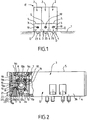
Fig. 1 est une vue de face représentant un ensemble de distribution, selon l'invention, avec ici pour l'exemple, trois distributeurs pneumatiques, et dispositifs d'isolation montés côte à côte sur l'embase. -
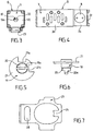
Fig. 2 est une vue latérale, à plus grande échelle avec parties arrachées, montrant un dispositif isolateur de pression selon l'invention. -
Fig. 3 est une vue côté gauche par rapport àFig. 2 , à plus petite échelle. -
Fig. 4 est une vue de dessus du dispositif deFig. 3 . -
Fig. 5 est une vue en bout à plus grande échelle d'une commande adaptée à un dispositif isolateur de pression selon l'invention. -
Fig. 6 est une vue en élévation latérale de la commande deFig. 5 , et -
Fig. 7 est une vue en bout, d'un dispositif de blocage adapté à un dispositif isolateur de pression selon l'invention, le dispositif de blocage étant incliné de 90° dans le sens horaire. - Dans toute la description qui suit d'un mode de réalisation d'un dispositif selon l'invention, les termes relatifs tels que « supérieur », « inférieur », « avant », « arrière », « horizontal » et « vertical » sont à interpréter lorsque le dispositif D selon l'invention est installé entre une embase 1 et un distributeur 2, en situation de fonctionnement.
- On peut voir sur
Fig. 1 un ensemble de distribution pneumatique E comprenant une embase 1 de distribution sur laquelle sont montés par exemple trois distributeurs pneumatiques 2, ou électropneumatiques, comprenant chacun un dispositif isolateur de pression D selon l'invention. - En variante, les distributeurs peuvent être montés dans un ilot de distribution, formé par un ensemble de distributeurs placés sur des embases communes.
- Chaque distributeur 2 est alimenté en pression par l'intermédiaire du dispositif isolateur D sur lequel il est monté.
- Il est visible sur
Fig. 2 que le dispositif isolateur D comporte un corps 3 en deux parties. Le corps 3, de forme sensiblement parallélépipédique, comporte une face inférieure formant face d'alimentation 4 et une face supérieure formant une face de distribution 5. - Une première partie 3a située en partie avant comprend un élément d'obturation 6 apte à occuper une position ouverte où la face de distribution 5 est en communication fluide avec la face d'alimentation 4, et une position fermée où la face de distribution 5 n'est pas en communication fluide avec la face d'alimentation 4.
- Une seconde partie 3b située en partie arrière assure la communication fluide avec l'embase 1 et le distributeur 2.
- Dans la partie supérieure de la première partie 3a, une chambre d'admission 7, fermée par un bouchon 8, est ménagée.
- Le bouchon 8 est partiellement évidé et l'évidement ainsi créé prolonge la chambre d'admission 7. Des joints 9a et 9b sont prévus pour assurer l'étanchéité entre le bouchon 8 et le corps 3.
- Sous le bouchon 8, un logement 10 reçoit l'élément d'obturation 6 de forme sphérique. Un siège supérieur 11a est interposé entre le bouchon 8 et l'élément d'obturation 6. Le siège supérieur 11a comporte une face supérieure plane sur laquelle s'exerce l'effort d'un ressort hélicoïdal 12a, dont l'unique spire est représentée écrasée
Fig. 2 , prenant appui sur le bouchon 8. Le siège supérieur 11a comporte une face inférieure sphérique assurant un contact surfacique avec l'élément d'obturation. - Un siège inférieur 11b est interposé entre l'élément d'obturation 6 et le fond de logement 10. Le siège inférieur 11 b comporte une face supérieure sphérique assurant un contact surfacique avec l'élément d'obturation 6. Le siège inférieur 11b comporte également une face inférieure plane sur laquelle s'exerce l'effort d'un ressort hélicoïdal 12b, ne comportant qu'une seule spire, prenant appui sur le corps 3.
- Les sièges 11a et 11 b sont percés en leur milieu de manière à permettre le passage du fluide vers et à partir de l'élément d'obturation 6.
- Sous le siège inférieur 11 b, un orifice de sortie 13 est prévu.
- La zone du logement 10 située entre les sièges 11 a et 11 b, à l'extérieur de l'élément d'obturation 6, forme une chambre d'échappement 14.
- L'élément d'obturation 6 est traversé par un canal 15 dont l'axe passe par le centre géométrique de la sphère formée par la surface de l'élément d'obturation 6. Le canal 15, lorsque son axe est vertical, met en relation la chambre d'admission 7 et l'orifice de sortie 13.
- L'élément d'obturation 6 comporte également un conduit d'échappement 16 d'axe orthogonal à l'axe du canal 15. Le conduit 16 et le canal 15 ne sont pas sécants. Lorsque l'axe du conduit 16 se trouve dans un plan vertical, le conduit 16 met en relation la chambre d'admission 7 et la chambre d'échappement 14. La chambre d'échappement communique avec un orifice d'échappement 17. Le conduit 16 présente une section transversale suffisamment réduite pour assurer une mise à l'échappement progressive du circuit aval commandé par le distributeur ou électro-distributeur.
- Le corps 3 comporte un alésage 18 dont l'axe passe par le centre géométrique de la sphère formée par la surface de l'élément d'obturation 6.
- Une commande 19 comportant un doigt cylindrique 20 est logée dans l'alésage 18. L'extrémité du doigt 20 comporte deux dégagements pour former un tenon 20a (
Fig. 6 ) qui pénètre dans une rainure 6a prévue dans l'élément d'obturation 6. - La surface extérieure de la commande 19 comporte une rainure 19a permettant de faire pivoter la commande 19 à l'aide d'un outil du type tournevis. La commande 19 comporte également au voisinage de sa surface extérieure un plateau 21 orthogonal à l'axe géométrique du doigt 20. La périphérie du plateau 21 comporte deux encoches 21a et 21b (
Fig. 5 ) formant un angle de 90° l'une par rapport à l'autre. Un capot 22 est prévu pour maintenir la commande 19 en place de sorte que seules l'extrémité extérieure de la commande 19 et la rainure 19a sont visibles. - Une plaque de verrouillage 23 est également présente sous le capot 22. La plaque de verrouillage 23 est évidée et traversée par la commande 19. Un doigt 24 s'étend vers l'intérieur de l'évidemment et pénètre dans l'une des encoches 21 a, 21 b.
- En fonctionnement, en cas de défaillance du distributeur 2, l'action d'un opérateur sur la fente 19a de la commande 19 permet de faire pivoter le doigt 20 entraînant la rotation de l'élément d'obturation 6 par l'intermédiaire de la coopération entre le tenon 20a et la rainure 6a.
- La commande 19 permet de supprimer la communication entre la chambre d'admission 7 et l'orifice de sortie 13 par l'intermédiaire du canal 15.
- Le distributeur 2, monté sur le dispositif isolateur de pression D sur lequel a agi l'opérateur, se trouve alors isolé de l'embase 1. Il est alors possible de remplacer le distributeur 2 défaillant, l'embase 1 restant sous pression et permettant d'assurer le fonctionnement des autres distributeurs montés sur ladite embase1.
- La translation de la plaque 23 permet d'engager le doigt 24 dans l'une des encoches 21a, 21 b pour bloquer la rotation du plateau 21 et par là de la commande 19 évitant toute action intempestive sur la commande 19.
- La plaque 23 comporte une ouverture 25 en partie basse qui permet de mettre en place un dispositif de bocage, par exemple un cadenas, pour ainsi interdire tout mouvement de la plaque 23 et donc le déblocage de la commande 19. De cette façon l'isolation réalisée peut difficilement être mise en oeuvre par inadvertance, malveillance ou suite à une mauvaise compréhension du système par une personne non-habilitée.
Claims (6)
- Ensemble de distribution pneumatique ou électropneumatique (E) comprenant au moins un distributeur pneumatique ou électropneumatique (2) monté sur une embase de distribution (1), comprenant au moins un dispositif isolateur de pression (D) apte à isoler la pression d'alimentation du distributeur (2) de l'embase (1), caractérisé en ce qu'un dispositif de verrouillage (23) est prévu pour bloquer le dispositif isolateur de pression (D) en position ouverte ou en position fermée, le dispositif de blocage étant constitué d'une plaque (23), guidée en translation par rapport au corps (3), comprenant un doigt (24) apte à coopérer avec des logements (21 a, 21 b) prévus sur la commande (19).
- Dispositif isolateur de pression (D) pour ensemble selon la revendication 1 , caractérisé en ce qu'il comporte un corps (3), une face de distribution (5) apte à être reliée au distributeur pneumatique (2), une face d'alimentation (4) apte à être reliée à l'embase d'alimentation (1) et un élément d'obturation (6) apte à occuper une position ouverte où la face de distribution (5) est en communication fluide avec la face d'alimentation (4), et une position fermée où la face de distribution (5) n'est pas en communication fluide avec la face d'alimentation (4).
- Dispositif isolateur de pression (D) selon la revendication 2, caractérisé en ce que l'élément d'obturation (6) est une sphère traversée par un orifice cylindrique (15) apte à pivoter autour d'un axe orthogonal à l'axe de l'orifice cylindrique (15).
- Dispositif isolateur de pression (D) selon la revendication 2 ou 3, caractérisé en ce que la surface latérale de l'élément d'obturation comporte une fente (6a) apte à coopérer avec une commande (19) montée pivotante par rapport au corps (3).
- Dispositif isolateur de pression (D) selon la revendication 2, 3 ou 4, caractérisé en ce que l'élément d'obturation (6) comporte un orifice d'échappement (16) apte, lorsque le dispositif isolateur de pression (D) est en position fermée, à mettre en communication les orifices d'utilisation de la face d'alimentation (5) avec une sortie d'échappement (17).
- Dispositif isolateur de pression (D) selon la revendication 1, caractérisé en ce que la plaque (23) comprend une ouverture (25) permettant la pose d'un dispositif de sécurité.
Applications Claiming Priority (1)
| Application Number | Priority Date | Filing Date | Title |
|---|---|---|---|
| FR0804530A FR2934880B1 (fr) | 2008-08-08 | 2008-08-08 | Dispositif isolateur de pression. |
Publications (2)
| Publication Number | Publication Date |
|---|---|
| EP2151587A1 EP2151587A1 (fr) | 2010-02-10 |
| EP2151587B1 true EP2151587B1 (fr) | 2016-03-30 |
Family
ID=40548625
Family Applications (1)
| Application Number | Title | Priority Date | Filing Date |
|---|---|---|---|
| EP09167262.6A Not-in-force EP2151587B1 (fr) | 2008-08-08 | 2009-08-05 | Dispositif isolateur de pression |
Country Status (3)
| Country | Link |
|---|---|
| EP (1) | EP2151587B1 (fr) |
| ES (1) | ES2577543T3 (fr) |
| FR (1) | FR2934880B1 (fr) |
Family Cites Families (4)
| Publication number | Priority date | Publication date | Assignee | Title |
|---|---|---|---|---|
| JPH1038119A (ja) * | 1996-07-26 | 1998-02-13 | Ckd Corp | マニホールド |
| WO2000050793A1 (fr) * | 1999-02-24 | 2000-08-31 | Water Valves Australia Pty. Ltd. | Accessoires de compteur a eau |
| US6871576B2 (en) * | 2003-02-19 | 2005-03-29 | Peter Vari | Hydraulic isolation valve |
| DE202005016766U1 (de) * | 2005-10-26 | 2006-01-12 | Festo Ag & Co. | Ventilbatterie |
-
2008
- 2008-08-08 FR FR0804530A patent/FR2934880B1/fr not_active Expired - Fee Related
-
2009
- 2009-08-05 ES ES09167262.6T patent/ES2577543T3/es active Active
- 2009-08-05 EP EP09167262.6A patent/EP2151587B1/fr not_active Not-in-force
Also Published As
| Publication number | Publication date |
|---|---|
| EP2151587A1 (fr) | 2010-02-10 |
| ES2577543T3 (es) | 2016-07-15 |
| FR2934880A1 (fr) | 2010-02-12 |
| FR2934880B1 (fr) | 2014-03-14 |
Similar Documents
| Publication | Publication Date | Title |
|---|---|---|
| EP2268964B1 (fr) | Ensemble comprenant un robinet et un chapeau de protection, bouteille comprenant un tel ensemble | |
| EP1979625B1 (fr) | Dispositif de commande d'un circuit consommateur de gaz comprime et generateur de vide faisant application | |
| EP1943458B1 (fr) | Dispositif de commande du remplissage et/ou du soutirage de fluide et reservoir comportant un tel dispositif | |
| EP0150143B1 (fr) | Appareil détendeur perfectionné | |
| LU100263B1 (en) | Compact gas cylinder valve with residual pressure function | |
| FR2526355A1 (fr) | Dispositif de retenue a depression, notamment pour le maintien en position d'un article sur un support | |
| EP2250426B1 (fr) | Dispositif de remplissage et de distribution de gaz et procede de remplissage | |
| FR2655571A1 (fr) | Dispositif support de buses, a changement rapide. | |
| EP1346946A1 (fr) | Pistolet à fonctionnement sécurisé et installation de remplissage comprenant un tel pistolet | |
| EP3693653B1 (fr) | Dispositif de fourniture de fluide sous pression et ensemble de stockage(s) de fluide sous pression comprenant un tel dispositif | |
| CA2765629A1 (fr) | Detendeur avec obturateur et selecteur de debit | |
| EP2780624B1 (fr) | Robinet pour bouteille de gaz équipé d'un volant commandant un clapet de pression résiduelle et un clapet de fermeture | |
| EP3693654B1 (fr) | Dispositif de fourniture de fluide sous pression et ensemble de stockage(s) de fluide sous pression comprenant un tel dispositif | |
| EP2151587A1 (fr) | Dispositif isolateur de pression | |
| EP1103991B1 (fr) | Electrovanne à poussoir de commande manuelle | |
| EP3831676B1 (fr) | Dispositif d'actionnement d'un systeme de freinage ferroviaire et vehicule ferroviaire pourvu d'un tel dispositif d'actionnement | |
| WO2019211566A1 (fr) | Système de prélèvement d'air equipé d'une vanne de surpression | |
| FR3056677A1 (fr) | Robinet pour fluide sous pression | |
| EP1054199A1 (fr) | Vanne motorisée pour la constitution d'un ensemble de distribution sélective d'un fluide de circulation | |
| EP1317636B1 (fr) | Robinet-detendeur a montage rapide sur une bouteille de gaz | |
| EP0993583B1 (fr) | Robinet pour appareil a gaz, et procede de calibrage d'un tel robinet | |
| FR2654350A1 (fr) | Poste a soupape d'alarme pour installations d'extinction des incendies. | |
| FR2896724A1 (fr) | Vanne de gonflage, de degonflage et de mesure de la pression dans une capacite | |
| WO2025133117A1 (fr) | Bloc hydraulique et ensemble d'électrovannes pour véhicule automobile | |
| FR2502280A1 (fr) | Robinet pour fluides liquides et gazeux |
Legal Events
| Date | Code | Title | Description |
|---|---|---|---|
| PUAI | Public reference made under article 153(3) epc to a published international application that has entered the european phase |
Free format text: ORIGINAL CODE: 0009012 |
|
| 17P | Request for examination filed |
Effective date: 20090807 |
|
| AK | Designated contracting states |
Kind code of ref document: A1 Designated state(s): AT BE BG CH CY CZ DE DK EE ES FI FR GB GR HR HU IE IS IT LI LT LU LV MC MK MT NL NO PL PT RO SE SI SK SM TR |
|
| AX | Request for extension of the european patent |
Extension state: AL BA RS |
|
| 17Q | First examination report despatched |
Effective date: 20100805 |
|
| GRAP | Despatch of communication of intention to grant a patent |
Free format text: ORIGINAL CODE: EPIDOSNIGR1 |
|
| GRAP | Despatch of communication of intention to grant a patent |
Free format text: ORIGINAL CODE: EPIDOSNIGR1 |
|
| INTG | Intention to grant announced |
Effective date: 20151019 |
|
| GRAS | Grant fee paid |
Free format text: ORIGINAL CODE: EPIDOSNIGR3 |
|
| GRAA | (expected) grant |
Free format text: ORIGINAL CODE: 0009210 |
|
| AK | Designated contracting states |
Kind code of ref document: B1 Designated state(s): AT BE BG CH CY CZ DE DK EE ES FI FR GB GR HR HU IE IS IT LI LT LU LV MC MK MT NL NO PL PT RO SE SI SK SM TR |
|
| REG | Reference to a national code |
Ref country code: GB Ref legal event code: FG4D Free format text: NOT ENGLISH |
|
| REG | Reference to a national code |
Ref country code: CH Ref legal event code: EP |
|
| REG | Reference to a national code |
Ref country code: AT Ref legal event code: REF Ref document number: 785731 Country of ref document: AT Kind code of ref document: T Effective date: 20160415 |
|
| REG | Reference to a national code |
Ref country code: IE Ref legal event code: FG4D Free format text: LANGUAGE OF EP DOCUMENT: FRENCH |
|
| REG | Reference to a national code |
Ref country code: DE Ref legal event code: R096 Ref document number: 602009037210 Country of ref document: DE |
|
| REG | Reference to a national code |
Ref country code: ES Ref legal event code: FG2A Ref document number: 2577543 Country of ref document: ES Kind code of ref document: T3 Effective date: 20160715 |
|
| REG | Reference to a national code |
Ref country code: LT Ref legal event code: MG4D |
|
| PG25 | Lapsed in a contracting state [announced via postgrant information from national office to epo] |
Ref country code: HR Free format text: LAPSE BECAUSE OF FAILURE TO SUBMIT A TRANSLATION OF THE DESCRIPTION OR TO PAY THE FEE WITHIN THE PRESCRIBED TIME-LIMIT Effective date: 20160330 Ref country code: FI Free format text: LAPSE BECAUSE OF FAILURE TO SUBMIT A TRANSLATION OF THE DESCRIPTION OR TO PAY THE FEE WITHIN THE PRESCRIBED TIME-LIMIT Effective date: 20160330 Ref country code: GR Free format text: LAPSE BECAUSE OF FAILURE TO SUBMIT A TRANSLATION OF THE DESCRIPTION OR TO PAY THE FEE WITHIN THE PRESCRIBED TIME-LIMIT Effective date: 20160701 Ref country code: NO Free format text: LAPSE BECAUSE OF FAILURE TO SUBMIT A TRANSLATION OF THE DESCRIPTION OR TO PAY THE FEE WITHIN THE PRESCRIBED TIME-LIMIT Effective date: 20160630 |
|
| REG | Reference to a national code |
Ref country code: NL Ref legal event code: MP Effective date: 20160330 |
|
| REG | Reference to a national code |
Ref country code: AT Ref legal event code: MK05 Ref document number: 785731 Country of ref document: AT Kind code of ref document: T Effective date: 20160330 |
|
| REG | Reference to a national code |
Ref country code: FR Ref legal event code: PLFP Year of fee payment: 8 |
|
| PG25 | Lapsed in a contracting state [announced via postgrant information from national office to epo] |
Ref country code: LV Free format text: LAPSE BECAUSE OF FAILURE TO SUBMIT A TRANSLATION OF THE DESCRIPTION OR TO PAY THE FEE WITHIN THE PRESCRIBED TIME-LIMIT Effective date: 20160330 Ref country code: LT Free format text: LAPSE BECAUSE OF FAILURE TO SUBMIT A TRANSLATION OF THE DESCRIPTION OR TO PAY THE FEE WITHIN THE PRESCRIBED TIME-LIMIT Effective date: 20160330 Ref country code: SE Free format text: LAPSE BECAUSE OF FAILURE TO SUBMIT A TRANSLATION OF THE DESCRIPTION OR TO PAY THE FEE WITHIN THE PRESCRIBED TIME-LIMIT Effective date: 20160330 |
|
| PG25 | Lapsed in a contracting state [announced via postgrant information from national office to epo] |
Ref country code: NL Free format text: LAPSE BECAUSE OF FAILURE TO SUBMIT A TRANSLATION OF THE DESCRIPTION OR TO PAY THE FEE WITHIN THE PRESCRIBED TIME-LIMIT Effective date: 20160330 |
|
| PG25 | Lapsed in a contracting state [announced via postgrant information from national office to epo] |
Ref country code: IS Free format text: LAPSE BECAUSE OF FAILURE TO SUBMIT A TRANSLATION OF THE DESCRIPTION OR TO PAY THE FEE WITHIN THE PRESCRIBED TIME-LIMIT Effective date: 20160730 Ref country code: EE Free format text: LAPSE BECAUSE OF FAILURE TO SUBMIT A TRANSLATION OF THE DESCRIPTION OR TO PAY THE FEE WITHIN THE PRESCRIBED TIME-LIMIT Effective date: 20160330 Ref country code: PL Free format text: LAPSE BECAUSE OF FAILURE TO SUBMIT A TRANSLATION OF THE DESCRIPTION OR TO PAY THE FEE WITHIN THE PRESCRIBED TIME-LIMIT Effective date: 20160330 |
|
| PG25 | Lapsed in a contracting state [announced via postgrant information from national office to epo] |
Ref country code: SK Free format text: LAPSE BECAUSE OF FAILURE TO SUBMIT A TRANSLATION OF THE DESCRIPTION OR TO PAY THE FEE WITHIN THE PRESCRIBED TIME-LIMIT Effective date: 20160330 Ref country code: CZ Free format text: LAPSE BECAUSE OF FAILURE TO SUBMIT A TRANSLATION OF THE DESCRIPTION OR TO PAY THE FEE WITHIN THE PRESCRIBED TIME-LIMIT Effective date: 20160330 Ref country code: AT Free format text: LAPSE BECAUSE OF FAILURE TO SUBMIT A TRANSLATION OF THE DESCRIPTION OR TO PAY THE FEE WITHIN THE PRESCRIBED TIME-LIMIT Effective date: 20160330 Ref country code: PT Free format text: LAPSE BECAUSE OF FAILURE TO SUBMIT A TRANSLATION OF THE DESCRIPTION OR TO PAY THE FEE WITHIN THE PRESCRIBED TIME-LIMIT Effective date: 20160801 Ref country code: SM Free format text: LAPSE BECAUSE OF FAILURE TO SUBMIT A TRANSLATION OF THE DESCRIPTION OR TO PAY THE FEE WITHIN THE PRESCRIBED TIME-LIMIT Effective date: 20160330 Ref country code: RO Free format text: LAPSE BECAUSE OF FAILURE TO SUBMIT A TRANSLATION OF THE DESCRIPTION OR TO PAY THE FEE WITHIN THE PRESCRIBED TIME-LIMIT Effective date: 20160330 |
|
| PG25 | Lapsed in a contracting state [announced via postgrant information from national office to epo] |
Ref country code: BE Free format text: LAPSE BECAUSE OF NON-PAYMENT OF DUE FEES Effective date: 20160831 |
|
| REG | Reference to a national code |
Ref country code: DE Ref legal event code: R097 Ref document number: 602009037210 Country of ref document: DE |
|
| PG25 | Lapsed in a contracting state [announced via postgrant information from national office to epo] |
Ref country code: DK Free format text: LAPSE BECAUSE OF FAILURE TO SUBMIT A TRANSLATION OF THE DESCRIPTION OR TO PAY THE FEE WITHIN THE PRESCRIBED TIME-LIMIT Effective date: 20160330 |
|
| PLBE | No opposition filed within time limit |
Free format text: ORIGINAL CODE: 0009261 |
|
| STAA | Information on the status of an ep patent application or granted ep patent |
Free format text: STATUS: NO OPPOSITION FILED WITHIN TIME LIMIT |
|
| 26N | No opposition filed |
Effective date: 20170103 |
|
| PG25 | Lapsed in a contracting state [announced via postgrant information from national office to epo] |
Ref country code: MC Free format text: LAPSE BECAUSE OF FAILURE TO SUBMIT A TRANSLATION OF THE DESCRIPTION OR TO PAY THE FEE WITHIN THE PRESCRIBED TIME-LIMIT Effective date: 20160330 |
|
| REG | Reference to a national code |
Ref country code: CH Ref legal event code: PL |
|
| GBPC | Gb: european patent ceased through non-payment of renewal fee |
Effective date: 20160805 |
|
| PG25 | Lapsed in a contracting state [announced via postgrant information from national office to epo] |
Ref country code: LI Free format text: LAPSE BECAUSE OF NON-PAYMENT OF DUE FEES Effective date: 20160831 Ref country code: CH Free format text: LAPSE BECAUSE OF NON-PAYMENT OF DUE FEES Effective date: 20160831 |
|
| PG25 | Lapsed in a contracting state [announced via postgrant information from national office to epo] |
Ref country code: SI Free format text: LAPSE BECAUSE OF FAILURE TO SUBMIT A TRANSLATION OF THE DESCRIPTION OR TO PAY THE FEE WITHIN THE PRESCRIBED TIME-LIMIT Effective date: 20160330 |
|
| REG | Reference to a national code |
Ref country code: IE Ref legal event code: MM4A |
|
| PG25 | Lapsed in a contracting state [announced via postgrant information from national office to epo] |
Ref country code: IE Free format text: LAPSE BECAUSE OF NON-PAYMENT OF DUE FEES Effective date: 20160805 Ref country code: GB Free format text: LAPSE BECAUSE OF NON-PAYMENT OF DUE FEES Effective date: 20160805 |
|
| REG | Reference to a national code |
Ref country code: FR Ref legal event code: PLFP Year of fee payment: 9 |
|
| PG25 | Lapsed in a contracting state [announced via postgrant information from national office to epo] |
Ref country code: LU Free format text: LAPSE BECAUSE OF NON-PAYMENT OF DUE FEES Effective date: 20160805 |
|
| PG25 | Lapsed in a contracting state [announced via postgrant information from national office to epo] |
Ref country code: HU Free format text: LAPSE BECAUSE OF FAILURE TO SUBMIT A TRANSLATION OF THE DESCRIPTION OR TO PAY THE FEE WITHIN THE PRESCRIBED TIME-LIMIT; INVALID AB INITIO Effective date: 20090805 Ref country code: CY Free format text: LAPSE BECAUSE OF FAILURE TO SUBMIT A TRANSLATION OF THE DESCRIPTION OR TO PAY THE FEE WITHIN THE PRESCRIBED TIME-LIMIT Effective date: 20160330 |
|
| PG25 | Lapsed in a contracting state [announced via postgrant information from national office to epo] |
Ref country code: MK Free format text: LAPSE BECAUSE OF FAILURE TO SUBMIT A TRANSLATION OF THE DESCRIPTION OR TO PAY THE FEE WITHIN THE PRESCRIBED TIME-LIMIT Effective date: 20160330 Ref country code: TR Free format text: LAPSE BECAUSE OF FAILURE TO SUBMIT A TRANSLATION OF THE DESCRIPTION OR TO PAY THE FEE WITHIN THE PRESCRIBED TIME-LIMIT Effective date: 20160330 Ref country code: MT Free format text: LAPSE BECAUSE OF FAILURE TO SUBMIT A TRANSLATION OF THE DESCRIPTION OR TO PAY THE FEE WITHIN THE PRESCRIBED TIME-LIMIT Effective date: 20160330 |
|
| PG25 | Lapsed in a contracting state [announced via postgrant information from national office to epo] |
Ref country code: BG Free format text: LAPSE BECAUSE OF FAILURE TO SUBMIT A TRANSLATION OF THE DESCRIPTION OR TO PAY THE FEE WITHIN THE PRESCRIBED TIME-LIMIT Effective date: 20160330 |
|
| REG | Reference to a national code |
Ref country code: FR Ref legal event code: PLFP Year of fee payment: 10 |
|
| PGFP | Annual fee paid to national office [announced via postgrant information from national office to epo] |
Ref country code: IT Payment date: 20220720 Year of fee payment: 14 Ref country code: ES Payment date: 20220901 Year of fee payment: 14 Ref country code: DE Payment date: 20220720 Year of fee payment: 14 |
|
| PGFP | Annual fee paid to national office [announced via postgrant information from national office to epo] |
Ref country code: FR Payment date: 20220721 Year of fee payment: 14 |
|
| REG | Reference to a national code |
Ref country code: DE Ref legal event code: R119 Ref document number: 602009037210 Country of ref document: DE |
|
| PG25 | Lapsed in a contracting state [announced via postgrant information from national office to epo] |
Ref country code: IT Free format text: LAPSE BECAUSE OF NON-PAYMENT OF DUE FEES Effective date: 20230805 Ref country code: FR Free format text: LAPSE BECAUSE OF NON-PAYMENT OF DUE FEES Effective date: 20230831 Ref country code: DE Free format text: LAPSE BECAUSE OF NON-PAYMENT OF DUE FEES Effective date: 20240301 |
|
| REG | Reference to a national code |
Ref country code: ES Ref legal event code: FD2A Effective date: 20240927 |
|
| PG25 | Lapsed in a contracting state [announced via postgrant information from national office to epo] |
Ref country code: ES Free format text: LAPSE BECAUSE OF NON-PAYMENT OF DUE FEES Effective date: 20230806 |
|
| PG25 | Lapsed in a contracting state [announced via postgrant information from national office to epo] |
Ref country code: ES Free format text: LAPSE BECAUSE OF NON-PAYMENT OF DUE FEES Effective date: 20230806 |