EP2151380B1 - Integrated duct design for an unmanned aerial vehicle - Google Patents
Integrated duct design for an unmanned aerial vehicle Download PDFInfo
- Publication number
- EP2151380B1 EP2151380B1 EP09161828.0A EP09161828A EP2151380B1 EP 2151380 B1 EP2151380 B1 EP 2151380B1 EP 09161828 A EP09161828 A EP 09161828A EP 2151380 B1 EP2151380 B1 EP 2151380B1
- Authority
- EP
- European Patent Office
- Prior art keywords
- duct
- uav
- fan
- length
- corners
- Prior art date
- Legal status (The legal status is an assumption and is not a legal conclusion. Google has not performed a legal analysis and makes no representation as to the accuracy of the status listed.)
- Not-in-force
Links
- 238000013461 design Methods 0.000 title description 3
- 230000005484 gravity Effects 0.000 claims description 6
- 239000011888 foil Substances 0.000 claims 4
- 239000000446 fuel Substances 0.000 description 10
- 238000012360 testing method Methods 0.000 description 4
- 230000003247 decreasing effect Effects 0.000 description 3
- 230000000694 effects Effects 0.000 description 3
- 238000009533 lab test Methods 0.000 description 2
- 238000000034 method Methods 0.000 description 2
- RZVHIXYEVGDQDX-UHFFFAOYSA-N 9,10-anthraquinone Chemical compound C1=CC=C2C(=O)C3=CC=CC=C3C(=O)C2=C1 RZVHIXYEVGDQDX-UHFFFAOYSA-N 0.000 description 1
- 238000013459 approach Methods 0.000 description 1
- 230000000903 blocking effect Effects 0.000 description 1
- 239000000356 contaminant Substances 0.000 description 1
- 238000001816 cooling Methods 0.000 description 1
- 238000002474 experimental method Methods 0.000 description 1
- 230000010006 flight Effects 0.000 description 1
- 230000008092 positive effect Effects 0.000 description 1
- 238000013519 translation Methods 0.000 description 1
Images


Classifications
-
- B—PERFORMING OPERATIONS; TRANSPORTING
- B64—AIRCRAFT; AVIATION; COSMONAUTICS
- B64C—AEROPLANES; HELICOPTERS
- B64C39/00—Aircraft not otherwise provided for
- B64C39/02—Aircraft not otherwise provided for characterised by special use
- B64C39/024—Aircraft not otherwise provided for characterised by special use of the remote controlled vehicle type, i.e. RPV
-
- B—PERFORMING OPERATIONS; TRANSPORTING
- B64—AIRCRAFT; AVIATION; COSMONAUTICS
- B64C—AEROPLANES; HELICOPTERS
- B64C27/00—Rotorcraft; Rotors peculiar thereto
- B64C27/20—Rotorcraft characterised by having shrouded rotors, e.g. flying platforms
-
- B—PERFORMING OPERATIONS; TRANSPORTING
- B64—AIRCRAFT; AVIATION; COSMONAUTICS
- B64U—UNMANNED AERIAL VEHICLES [UAV]; EQUIPMENT THEREFOR
- B64U10/00—Type of UAV
- B64U10/10—Rotorcrafts
- B64U10/13—Flying platforms
-
- B—PERFORMING OPERATIONS; TRANSPORTING
- B64—AIRCRAFT; AVIATION; COSMONAUTICS
- B64U—UNMANNED AERIAL VEHICLES [UAV]; EQUIPMENT THEREFOR
- B64U30/00—Means for producing lift; Empennages; Arrangements thereof
- B64U30/20—Rotors; Rotor supports
Definitions
- the present invention describes a system and a method of creating increased storage on the UAV for a given inner diameter of the duct of the UAV.
- the duct of the UAV is shaped to provide additional storage between the inside and outside walls of the duct by creating a larger area between the inside and outside wall of the duct at intervals along the circumference of the duct.
- UAV 10 may have raised corners.
- the cross section of the duct 31 may be substantially square in a plane perpendicular to the axis of rotation of the fan.
- the corners 25 may extend further away from the axis of rotation, providing additional storage space in the direction of the plane perpendicular to the axis of rotation.
- Fig. 2e shows the cross-section of the duct 3 at the sidewall 13 and the corner 25.
- the increased thickness of the duct 3 at the corners 25 provides additional storage space for electronics and other equipment on the UAV 10.
- the airspeed is increased compared to the air passing over the thinner duct side wall 13. This results in areas of relatively lower pressure and higher airspeed at the duct corners 25, contributing to improved airflow and thrust for the UAV 10.
- the difference in airspeed and air pressure between the duct 31 at the corner 25 and the sidewall 13 for UAV 10 may be greater than the difference in airspeed and air pressure for the UAV 1 between the corner 5 and the sidewall 13 because of the greater distance the air must travel to reach the intake of the fan.
Description
- The present invention relates generally to an integrated duct design for a ducted fan vehicle. More specifically, the invention relates to an unmanned aerial vehicle (UAV) having a duct capable of storing electronics and equipment inside the duct.
- Unmanned aerial vehicles may have at least one ducted fan and a fan engine to drive the fan blades. The ducted fan produces an airstream that may enable the UAV to hover or move translationally parallel to the ground.
- UAV vehicles may be used to transport equipment, perform surveillance, obtain information from sensors, place sensors or other payload in a dangerous or inaccessible area, or to perform contaminant testing. In order to reach the target destination, and to perform the desired task, UAVs may need to store equipment such as avionics, controls, payload, and sensing equipment.
-
EP 2 147 858 A2
U.S. Patent No. 2,077,471 to Fink discloses an aircraft that includes a housing and propellers mounted for rotation in planes disposed substantially midway of the upper and lower sides of the housing.
U.S. Patent No. 6,575,402 to Scott discloses a cooling system for a hybrid aircraft, which includes a body with a toroidal portion.
EP 0 553 490
U.S. Patent No. 4,196,577 to Mutrux discloses an aircraft that comprises a generally annular wing structure surrounding a circular central structure to form an annular air duct. - Some UAVs may store such equipment in external pods attached to the duct. These pods may cause a shift in the center of gravity, may create negative interference with airflow characteristics inside the duct by blocking air intake and exhaust, and may create additional drag on the UAV when the UAV is in forward flight. Additionally, the added weight of the equipment may require additional engine capacity and fuel storage capacity. The additional engine capacity and additional fuel that must be carried further add to the weight, and may therefore decrease the fuel efficiency of the vehicle.
- Alternatively, some UAVs may store equipment inside the duct. UAVs may typically have a circular duct. Storing equipment inside the duct may require that the thickness and the diameter of the circular duct be increased. Increasing the diameter and the thickness of the circular duct may affect a large number of design criteria for the UAV, such as the center of gravity, engine size, thrust power, fuel requirements, weight, controls, as well as other possible effects.
- Therefore, there is a need for an improved means of storing equipment on a ducted fan aerial vehicle.
- The present disclosure describes a ducted-fan unmanned air vehicle (UAV) having space inside the duct for carrying equipment or cargo. UAVs may carry equipment on board, such as avionics equipment, control equipment, sensors, and fuel. Traditionally, equipment carried by the UAV may be stored in removable or fixed storage pods attached to the duct of the UAV. These storage pods may create interference with airflow and may cause losses in overall efficiency due to the disturbance of the airflow around the UAV. One approach to providing increased area for storing equipment and payload on the UAV was to create a duct having space inside it. If additional storage was necessary, the size of the outer diameter of the circular duct could be expanded.
- An improved system and method for storing equipment on the UAV creates additional space between the inner and outer wall of the duct at specified intervals along the circumference of the duct. This may create "corners" on the duct having increased storage capacity. Using these corners on the duct of the UAV may result in improved fuel efficiency and thrust of the UAV fan over other systems in which pods are attached to the circumference of the duct of the UAV, or in systems in which the outer diameter of the duct was increased to accommodate additional equipment inside the duct.
- In another example not covered by the present invention, the area on the duct used to store equipment may be further increased by raising the corners of the duct in a direction substantially parallel to the axis of rotation of the fan.
- Creating space inside the duct in corners located on the perimeter of the duct of the UAV and raising the corners of the duct in a direction parallel to the axis of rotation of the fan may result in increased efficiency, decreased turbulence, and improved thrust over systems having equivalent cargo capacity in which the duct outer perimeter is circular or in which storage pods are attached to the perimeter of the duct of the UAV.
- Other objects, advantages and novel features, and further scope of applicability of the present disclosure will be set forth in part in the detailed description to follow, taken in conjunction with the accompanying drawings, and in part will become apparent to those skilled in the art upon examination of the following, or may be learned by practice of the disclosure. Further, it is understood that this summary is merely an example and is not intended to limit the scope of the invention as claimed.
- Presently preferred embodiments are described below in conjunction with the appended drawing figures, wherein like reference numerals refer to like elements in the various figures, and wherein:
-
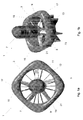
Fig. 1a is a pictorial representation of a top view of a ducted fan UAV having a substantially square outer duct, according to an example. -
Fig. 1b is a pictorial representation of a perspective view of a ducted fan UAV having a substantially square perimeter, according to an example. -
Fig. 1c is a pictorial representation of a side view of a ducted fan UAV having a substantially square perimeter, according to an example. -
Fig. 1d is a pictorial representation of a side view of a ducted fan UAV having a substantially square perimeter and rotated 45° around the axis of rotation from the view ofFig. 1c , according to an example. -
Fig. 1e is a graph of two cross-sections of the duct of the UAV having a substantially square perimeter, according to an example. -
Figures 2a-2e represent an example of a ducted fan UAV not covered by the present invention. -
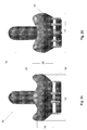
Fig. 2a is a pictorial representation of a top view of a ducted fan UAV having a substantially square perimeter and raised corners, according to an example. -
Fig. 2b is a pictorial representation of a perspective view of a ducted fan UAV having a substantially square perimeter and raised corners, according to an example. -
Fig. 2c is a pictorial representation of a side view of a ducted fan UAV having a substantially square perimeter and raised corners, according to an example. -
Fig. 2d is a pictorial representation of a side view of a ducted fan UAV having a substantially square perimeter and raised corners, and rotated 45° around the axis of rotation from the view ofFig. 1c , according to an example. -
Fig. 2e is a graph of two cross-sections of the duct of the UAV having a substantially square perimeter and raised corners, according to an example. - Ducted-fan UAVs are known for their superior stationary aerodynamic hovering performance, three-dimensional precision position hold, low speed flights, precision vertical take-off and landing ("VTOL") and safe close-range operations. Ducted fan air-vehicles may be preprogrammed to perform operations autonomously, or they may be controlled by a human operator. Therefore, ducted fan air-vehicles may be unmanned aerial vehicles.
- UAVs may have avionics equipment on board to control the flight and operation of the UAV. For instance, the avionics may control the direction, flight, stability compensation, and other aspects of flight control. Additionally, UAVs may carry a variety of equipment on board tailored to the mission the UAVs are assigned to accomplish. UAVs may carry sensors on board to obtain information about surroundings, or the UAVs may carry a payload to be deposited at a target site. The UAV engine to drive the UAV requires that fuel be carried on board the UAV. The avionics equipment, sensors, payload, and fuel may be stored on the UAV.
- The present invention describes a system and a method of creating increased storage on the UAV for a given inner diameter of the duct of the UAV. The duct of the UAV is shaped to provide additional storage between the inside and outside walls of the duct by creating a larger area between the inside and outside wall of the duct at intervals along the circumference of the duct.
- For instance, as shown in
Fig. 1a , the cross-section of theduct 3 on a plane substantially perpendicular to the axis of rotation of the fan may have a substantially square shape. While the inner diameter of theduct 3 of theUAV 1 may remain circular, the outer profile of the duct may have a square shape. The additional interior space created between the inner and outer walls of the duct provides additional storage for equipment that may be carried on theUAV 1. Theduct 3 shown inFigs 1a-d has a substantially square perimeter; however, theduct 3 may have other numbers ofcorners 5. - The
UAV 1 ofFigs. 1a-1d has a fan withfan blades 9 driven byfan engine 7. Thefan stators 11 may hold theduct 3 stationary in relation to thefan engine 7. Theduct 3 hasduct corners 5 andduct side walls 13. Theduct side walls 13 may be thinner than theduct corners 5. The increased thickness of theduct corners 5 provides additional storage space for equipment to be stored on theUAV 1. -
Fig. 1b shows a side view of theUAV 1. Thelanding gear 23 may be located at the base of theUAV 1, and may increase the stability of theUAV 1 during landing. As shown inFig. 1b , the top surface of theduct 3 may have a substantially flat profile. -
Figs. 1c and 1d show side views of theUAV 1 indicating the difference between thelength 2 from onecorner 5 to theopposite corner 5, and thelength 4 from oneduct side wall 13 to the oppositeduct side wall 13. - The
length 2 of theUAV 1 shown inFigs. 1a-d is approximately 27% greater thanlength 4. However,lengths length 2 may ideally be in the range of 10-40% greater thanlength 4. The difference betweenlengths UAV 1 in a direction substantially perpendicular to the axis of rotation of the fan, and may affect overall vehicle performance. Therefore, the difference betweenlengths UAV 1 and the desired vehicle performance specifications. - The thickness of the
duct 3 may taper down to thebase 6. This tapered shape may provide improved vehicle performance, discussed further with respect toFigs. 1e . - In laboratory testing,
UAV 1 returned similar values for thrust, fuel efficiency, and stability to the values obtained for a traditional circular duct withoutduct corners 5. In some testing scenarios,UAV 1 actually showed improved thrust. This indicates that providing storage on theUAV 1 inside a squareduct having corners 5 may provide storage space without significantly negatively affecting the airflow characteristics and fan efficiency of theUAV 1. For instance, in laboratory tests on aUAV 1 having dimensions of 14" square and a weight of approximately 18.6 pounds, experimental data indicated that the thrust obtained by the fan was improved over a UAV having a traditional circular duct when both were in hover mode. In forward flight, thesquare UAV 1 performed slightly worse than the traditional circular duct. - The increased thrust may be attributed to the increased speed of the airflow as it flows over the thicker section of the
duct corners 5. Because air may travel a longer distance over the lip of theduct 3 to the intake of the fan, the airspeed may increase and the pressure at thecorners 5 may decrease. These factors may contribute to the improved overall thrust of theUAV 1. - Because the of the increased capacity in the
corners 5 of theduct 3, the center of gravity of theUAV 1 may be shifted downwardly relative to the top surface of theduct 3. In order to maintain the stability of theUAV 1, this shift in the center of gravity may be compensated for by shifting theengine 7 upward along the axis or rotation, or by shifting another component of theUAV 1 upward in order to compensate for the shift caused by storing equipment in theduct corners 5. -
Fig. 1e shows the cross-section of theduct 3 at thesidewall 13 and thecorner 5. The increased thickness of theduct 3 at thecorners 5 provides the additional storage space for electronics and other equipment on theUAV 1. As air passes over thethicker duct corner 5, the airspeed is increased compared to the air passing over the thinnerduct side wall 13. This results in areas of relatively lower pressure and higher airspeed at theduct corners 5, contributing to improved airflow and thrust for theUAV 1. Additionally, the cross-section view of both theduct corner 5 and theduct sidewall 13 shows a cross-sectional shape similar to that of an airfoil. Because of the reduced air pressure over the curved portion of theduct 3 due to the increased air velocity, a lifting force is created in the direction perpendicular to the axis of rotation. In forward flight, theUAV 1 may benefit from the increased lift due to the increased thickness of the duct at thecorners 5. For aUAV 1 in forward flight, acorner 5 located opposite the forward end of theUAV 1 may experience a lifting force at least partially in an upward direction. Thecorner 5 at the forward end of theUAV 1 may experience lifting force at least partially in a downward direction. However, because theUAV 1 in forward flight may experience air resistance in a direction opposite to the direction of translation because of the airflow that hits the duct corner outsidewall 17 for thecorner 5 on the forward end of theUAV 1, and to a lesser extent because of airflow that hits the duct corner insidewall 15 for thecorner 5 opposite the forward end of theUAV 1, the lateral effect of the air resistance may reduce the negative lift caused by airflow over thecorner 5 at the forward end of theUAV 1, and may increase the positive lift of thecorner 5 at the end opposite the forward end of theUAV 1. Therefore, the net lifting force may be positive. - Referring to
Fig. 2a-e , in an example not covered by the present invention,UAV 10 may have raised corners. The cross section of theduct 31 may be substantially square in a plane perpendicular to the axis of rotation of the fan. Alternatively, thecorners 25 may extend further away from the axis of rotation, providing additional storage space in the direction of the plane perpendicular to the axis of rotation. - Because the inner diameter of the duct of the
UAV 10 may remain circular and the outer perimeter of theduct 31 may have a substantially square shape, the space between the inner and outer walls of theduct 31 may provide storage space on theUAV 10. The raised corners may provide increased storage over the flat profiledduct 3 ofUAV 1. Additionally, if thecorners 25 are extended outwardly from the axis of rotation, additional storage space may be obtained at thecorners 25 in the direction of the plane substantially perpendicular to the axis of rotation. Theduct 31 shown inFigs 2a-d has a substantially square perimeter; however, theduct 31 may have other numbers ofcorners 25, and may havecorners 25 extended outwardly from the axis of rotation. - The
UAV 10 ofFigs. 2a-d has a fan withfan blades 9, afan engine 7,stators 11, andlanding gear 23 that function as described with respect toFigs. 1a-d . - The
duct 31 hasduct corners 25 andduct side walls 13. Theduct side walls 13 may be thinner than theduct corners 25. Additionally, as shown inFig. 2b , thecorners 25 may be raised in the direction of the axis of rotation. The additional height of theduct 31 in the direction of the axis of rotation provides additional storage for equipment on theUAV 10. The profile of theduct 31 on a plane parallel to the axis of rotation may have positive effects on thrust and fan efficiency, described further with respect toFigs. 2c-d . The increased thickness of theduct corners 25 provides additional storage space for equipment to be stored on theUAV 10. -
Fig. 2c and 2d show a side view of theUAV 10 indicating the difference in width of theUAV 10 between thelength 12 from onecorner 25 to theopposite corner 25, and thelength 14 from oneduct side wall 13 to the oppositeduct side wall 13. - The
length 12, from onecorner 25 to theopposite corner 25, of theUAV 10 shown inFigs. 2a-d is approximately 25% greater thanlength 14, from oneduct side wall 13 to the oppositeduct side wall 13. However, the difference betweenlengths lengths UAV 10 in a plane substantially perpendicular to the axis of rotation of the fan. Therefore, the difference betweenlengths UAV 10 and the desired fan performance specifications. -
Length 18 of theUAV 10 shown inFigs. 2a-d , between the low point of theduct side wall 13 and thebase 16, is approximately 17% greater thanlength 20, between the top of thecorner 25 and the base. The difference betweenlengths - The difference between
lengths UAV 10 in a direction substantially perpendicular to the axis of rotation of the fan. The difference betweenlengths UAV 10 in a direction substantially parallel to the axis of rotation of the fan. Additionally, the difference betweenlengths lengths Fig 2e . Therefore, the difference betweenlengths lengths UAV 10 and the desired fan performance specifications. - In laboratory testing,
UAV 10 showed improved values for thrust and fuel efficiency over values obtained for a traditional circular duct withoutduct corners 25. These experiments suggest that providing storage on theUAV 10 inside a square duct with raisedcorners 25 may enable cargo space to be provided onUAV 10 without significantly negatively affecting the airflow characteristics and fan efficiency of theUAV 10, and may possibly improve the overall performance of theUAV 10. For instance, in laboratory tests on aUAV 10 having dimensions of approximately 14" square and a weight of approximately 18.6 pounds, experimental data indicated that the thrust obtained byUAV 10 improved by 8% in hover mode, and by 16% in forward flight. - The increased thrust may be attributed to the increased speed of the airflow as is flows over the thicker section of the
duct corners 5. Because air may travel a longer distance over the raised corner of theduct 31 to the intake of the fan, the airspeed may increase and the pressure at thecorners 25 may decrease. Also, because air has a shorter distance to travel over the low, thinduct side wall 13, the airspeed may be relatively slower and the air pressure may be relatively higher than the airspeed and the air pressure at the top of thecorners 25. These factors may contribute to the improved overall thrust of theUAV 10. - Because the of the increased storage capacity in the
corners 25 of theduct 31, the center of gravity of theUAV 10 may be, depending on the dimensions of thecorners 25 and the difference of thelengths lengths duct sidewalls 13. This may provide advantages, in that the overall stability of theUAV 10 may be improved because the tipping moment of the top-mountedengine 7 may be decreased when theUAV 10 is in forward flight. Additionally, the raisedcorners 25 may provide an ideal place to connect engine mounts for theengine 7. Because locating engine mounts for theengine 7 higher in relation to the base of theengine 7 may provide increased stability due to the decreased tipping moment of theengine 7 when compared to an engine having engine mounts located at theengine 7 base, the engine mounts may be reduced in size. Thus, the overall weight of theUAV 10 may be reduced. Additionally, as discussed with respect toFig. 2e , the tapered shape of the duct may create lift on theUAV 1 in forward flight. -
Fig. 2e shows the cross-section of theduct 3 at thesidewall 13 and thecorner 25. The increased thickness of theduct 3 at thecorners 25 provides additional storage space for electronics and other equipment on theUAV 10. As air passes over the thicker andtaller duct corner 25, the airspeed is increased compared to the air passing over the thinnerduct side wall 13. This results in areas of relatively lower pressure and higher airspeed at theduct corners 25, contributing to improved airflow and thrust for theUAV 10. The difference in airspeed and air pressure between theduct 31 at thecorner 25 and thesidewall 13 forUAV 10 may be greater than the difference in airspeed and air pressure for theUAV 1 between thecorner 5 and thesidewall 13 because of the greater distance the air must travel to reach the intake of the fan. - Additionally, the cross-section view of both the
duct corner 25 and theduct sidewall 13 shows a cross-sectional shape similar to that of an airfoil, as described with respect toFig. 1e . As described with respect toFig. 1e , because of the reduced air pressure over the curved portion of theduct 31 due to the increased air velocity over theduct corners 25, a lifting force may created in the direction perpendicular to the axis of rotation. In forward flight, theUAV 10 may benefit from the increased lift due to the increased thickness and height of the duct at thecorners 25. For theUAV 10 in forward flight, acorner 25 located opposite the forward end of theUAV 10 may experience a lifting force at least partially in an upward direction. Thecorner 25 at the forward end of theUAV 10 may experience lifting force at least partially in a downward direction. However, because theUAV 10 in forward flight may experience air resistance in a direction opposite to the direction of travel because of the airflow that hits the duct corner outsidewall 17 for thecorner 25 on the forward end of theUAV 10, and to a lesser extent because of airflow that hits the duct corner insidewall 15 for thecorner 25 opposite the forward end of theUAV 10, the lateral force of the airflow may reduce the negative lift caused by airflow over thecorner 25 at the forward end of theUAV 10, and may increase the positive lift of thecorner 25 at the end opposite the forward end of theUAV 10. Therefore, the net lifting force may be positive. - It should be understood that the illustrated embodiments are examples only and should not be taken as limiting the scope of the present invention. The claims should not be read as limited to the described order or elements unless stated to that effect.
Claims (7)
- An unmanned aerial vehicle -UAV- (1) configured for hovering, the UAV comprising:a fan (7, 9); anda fan duct (3) defining an inside duct wall having a substantially circular cross-section, and an outside duct wall cooperatively engaged with the inside duct wall to form an at least partially enclosed space;the fan duct (3) including a plurality of enlarged areas of the at least partially enclosed space,characterized in thatthe plurality of enlarged areas extend outwardly in a direction perpendicular to an axis of rotation of the fan (7,9), forming duct corners (5), the fan duct further comprising duct side walls (13) thinner than the duct corners (5),wherein a first cross-section of the fan duct taken at a duct corner (5) defines a first air foil shape having a first leading edge and a second cross-section of the fan duct taken at a duct side wall (13) defines a second air foil shape having a second leading edge, andwherein both the first leading edge and the second leading edge are tangent to one single plane that is perpendicular to the axis of rotation of the fan.
- The UAV of claim 1, wherein a cross-section of the fan duct (3) on a plane substantially perpendicular to the axis rotation of the fan (7, 9) has a substantially square shape.
- The UAV of claim 1, wherein a first length (2) defines a distance between opposite duct corners (5) and a second length (4) defines a distance between opposite duct side_walls (13), and wherein the first length is greater than the second length.
- The UAV of claim 3, wherein the first length (2) is 27% greater than the second length (4).
- The UAV of claim 3, wherein the first length (2) is greater than the second length (4) by an amount within the range of 10% to 40%.
- The UAV of claim 1, further comprising an engine (7),
wherein the engine (7) drives the fan (7, 9),
wherein the engine (7) is fixed relative to the fan duct (3), and
wherein the engine (7) is located along the axis of rotation of the fan (7, 9) to at least partially compensate for a change to a center of gravity of the UAV caused by weight of equipment located in the plurality of enlarged areas. - The UAV of claim 1
wherein the first air foil shape comprises a first trailing edge and the second air foil shape comprises a second trailing edge, wherein the first and second trailing edges are approximately equidistant to the axis of rotation of the fan.
Applications Claiming Priority (1)
| Application Number | Priority Date | Filing Date | Title |
|---|---|---|---|
| US12/187,112 US20120234984A1 (en) | 2008-08-06 | 2008-08-06 | Integrated Duct Design for an Unmanned Aerial Vehicle |
Publications (3)
| Publication Number | Publication Date |
|---|---|
| EP2151380A2 EP2151380A2 (en) | 2010-02-10 |
| EP2151380A3 EP2151380A3 (en) | 2012-05-02 |
| EP2151380B1 true EP2151380B1 (en) | 2015-09-23 |
Family
ID=41199812
Family Applications (1)
| Application Number | Title | Priority Date | Filing Date |
|---|---|---|---|
| EP09161828.0A Not-in-force EP2151380B1 (en) | 2008-08-06 | 2009-06-03 | Integrated duct design for an unmanned aerial vehicle |
Country Status (3)
| Country | Link |
|---|---|
| US (1) | US20120234984A1 (en) |
| EP (1) | EP2151380B1 (en) |
| JP (1) | JP2010036888A (en) |
Families Citing this family (5)
| Publication number | Priority date | Publication date | Assignee | Title |
|---|---|---|---|---|
| US8240597B2 (en) * | 2008-08-06 | 2012-08-14 | Honeywell International Inc. | UAV ducted fan lip shaping |
| WO2011159374A2 (en) * | 2010-03-08 | 2011-12-22 | The Penn State Research Foundation | Double-ducted fan |
| SG2013004940A (en) * | 2013-01-21 | 2014-08-28 | Singapore Tech Aerospace Ltd | Method for improving crosswind stability of a propeller duct and a corresponding apparatus, system and computer readable medium |
| CN106864745A (en) * | 2017-02-09 | 2017-06-20 | 深圳市航宇航空科技有限公司 | A kind of balance piece for being used for five vane propeller culvert type unmanned vehicles |
| US11208197B2 (en) | 2017-03-31 | 2021-12-28 | Heka Aero LLC | Gimbaled fan |
Family Cites Families (16)
| Publication number | Priority date | Publication date | Assignee | Title |
|---|---|---|---|---|
| US2077471A (en) | 1935-05-04 | 1937-04-20 | Aero Improvements Inc | Aircraft |
| US3054578A (en) * | 1957-10-08 | 1962-09-18 | Cie De Rech S Et D Etudes Aero | Annular aircraft with elastic collector ring rim |
| US4037807A (en) * | 1972-09-01 | 1977-07-26 | Short Brothers And Harland Limited | Flight vehicle |
| US4196577A (en) | 1976-12-27 | 1980-04-08 | Citizen Watch Co., Ltd. | Electronic timepiece |
| US4132240A (en) * | 1977-03-28 | 1979-01-02 | General Electric Company | Variable double lip quiet inlet |
| US4196877A (en) * | 1977-06-15 | 1980-04-08 | Mutrux Jean L | Aircraft |
| US5035377A (en) * | 1985-02-28 | 1991-07-30 | Technolizenz Establishment | Free standing or aircraft lift generator |
| US5152478A (en) * | 1990-05-18 | 1992-10-06 | United Technologies Corporation | Unmanned flight vehicle including counter rotating rotors positioned within a toroidal shroud and operable to provide all required vehicle flight controls |
| CH685692A5 (en) * | 1992-01-29 | 1995-09-15 | Sky Disc Holding Sa C O Norasi | Aircraft. |
| US5295643A (en) * | 1992-12-28 | 1994-03-22 | Hughes Missile Systems Company | Unmanned vertical take-off and landing, horizontal cruise, air vehicle |
| US6170778B1 (en) * | 1999-04-22 | 2001-01-09 | Sikorsky Aircraft Corporation | Method of reducing a nose-up pitching moment on a ducted unmanned aerial vehicle |
| US6575402B1 (en) | 2002-04-17 | 2003-06-10 | Sikorsky Aircraft Corporation | Cooling system for a hybrid aircraft |
| JP4241331B2 (en) * | 2003-11-17 | 2009-03-18 | トヨタ自動車株式会社 | Vertical take-off and landing aircraft |
| US8387911B2 (en) | 2008-07-25 | 2013-03-05 | Honeywell International Inc. | Ducted fan core for use with an unmanned aerial vehicle |
| US20120153087A1 (en) * | 2008-08-06 | 2012-06-21 | Honeywell International Inc. | Modular Pods for Use with an Unmanned Aerial Vehicle |
| US8240597B2 (en) * | 2008-08-06 | 2012-08-14 | Honeywell International Inc. | UAV ducted fan lip shaping |
-
2008
- 2008-08-06 US US12/187,112 patent/US20120234984A1/en not_active Abandoned
-
2009
- 2009-06-03 EP EP09161828.0A patent/EP2151380B1/en not_active Not-in-force
- 2009-06-05 JP JP2009136226A patent/JP2010036888A/en active Pending
Also Published As
| Publication number | Publication date |
|---|---|
| EP2151380A2 (en) | 2010-02-10 |
| US20120234984A1 (en) | 2012-09-20 |
| JP2010036888A (en) | 2010-02-18 |
| EP2151380A3 (en) | 2012-05-02 |
Similar Documents
| Publication | Publication Date | Title |
|---|---|---|
| JP7466963B2 (en) | Large variable-speed tilt rotor eVTOL aircraft | |
| EP2151381B1 (en) | Ducted fan lip shaping for an unmanned aerial vehicle | |
| US10144509B2 (en) | High performance VTOL aircraft | |
| US8220737B2 (en) | VTOL aerial vehicle | |
| EP2760739B1 (en) | Control of an unmanned aerial vehicle | |
| AU673608B2 (en) | Ancillary aerodynamic structures for an unmanned aerial vehicle having ducted, coaxial counter-rotating rotors | |
| EP3087003B1 (en) | An unmanned aerial vehicle | |
| US20230150657A1 (en) | Manned and unmanned aircraft | |
| EP2151380B1 (en) | Integrated duct design for an unmanned aerial vehicle | |
| US8348190B2 (en) | Ducted fan UAV control alternatives | |
| US20230221733A1 (en) | Tilt-frame uav for agricultural air sampling with a propeller-thrust-governing system that facilitates vtol capability | |
| CN107539472A (en) | A kind of single lift culvert vertical take-off and landing aircraft based on tilting duct | |
| US11548636B2 (en) | Passive-release, snap-fit coupling devices for suspended payload containers of aircrafts | |
| EP2065304A2 (en) | Vehicular linear sensor system | |
| CN104229130A (en) | Four-rotor wing unmanned aerial vehicle with pneumatic structure | |
| US20210316848A1 (en) | Vertical take-off or landing (vtol) aerial device | |
| CN210761299U (en) | Unmanned aerial vehicle and unmanned aerial vehicle system | |
| CN204056295U (en) | Pneumatic structure four rotor unmanned aircraft | |
| US11760475B2 (en) | Articulated tiltrotor | |
| CN220640232U (en) | Aircraft with a plurality of aircraft body | |
| CN115892453A (en) | Flying body | |
| WO2020047045A1 (en) | Manned and unmanned aircraft | |
| CN115916645A (en) | Control of aircraft with vertical takeoff and landing capability |
Legal Events
| Date | Code | Title | Description |
|---|---|---|---|
| PUAI | Public reference made under article 153(3) epc to a published international application that has entered the european phase |
Free format text: ORIGINAL CODE: 0009012 |
|
| 17P | Request for examination filed |
Effective date: 20090603 |
|
| AK | Designated contracting states |
Kind code of ref document: A2 Designated state(s): AT BE BG CH CY CZ DE DK EE ES FI FR GB GR HR HU IE IS IT LI LT LU LV MC MK MT NL NO PL PT RO SE SI SK TR |
|
| AX | Request for extension of the european patent |
Extension state: AL BA RS |
|
| PUAL | Search report despatched |
Free format text: ORIGINAL CODE: 0009013 |
|
| AK | Designated contracting states |
Kind code of ref document: A3 Designated state(s): AT BE BG CH CY CZ DE DK EE ES FI FR GB GR HR HU IE IS IT LI LT LU LV MC MK MT NL NO PL PT RO SE SI SK TR |
|
| AX | Request for extension of the european patent |
Extension state: AL BA RS |
|
| RIC1 | Information provided on ipc code assigned before grant |
Ipc: B64C 39/02 20060101ALI20120328BHEP Ipc: B64C 27/20 20060101AFI20120328BHEP |
|
| 17Q | First examination report despatched |
Effective date: 20120426 |
|
| GRAP | Despatch of communication of intention to grant a patent |
Free format text: ORIGINAL CODE: EPIDOSNIGR1 |
|
| INTG | Intention to grant announced |
Effective date: 20150512 |
|
| GRAS | Grant fee paid |
Free format text: ORIGINAL CODE: EPIDOSNIGR3 |
|
| GRAA | (expected) grant |
Free format text: ORIGINAL CODE: 0009210 |
|
| AK | Designated contracting states |
Kind code of ref document: B1 Designated state(s): AT BE BG CH CY CZ DE DK EE ES FI FR GB GR HR HU IE IS IT LI LT LU LV MC MK MT NL NO PL PT RO SE SI SK TR |
|
| REG | Reference to a national code |
Ref country code: GB Ref legal event code: FG4D |
|
| REG | Reference to a national code |
Ref country code: CH Ref legal event code: EP |
|
| REG | Reference to a national code |
Ref country code: AT Ref legal event code: REF Ref document number: 751078 Country of ref document: AT Kind code of ref document: T Effective date: 20151015 |
|
| REG | Reference to a national code |
Ref country code: IE Ref legal event code: FG4D |
|
| REG | Reference to a national code |
Ref country code: DE Ref legal event code: R096 Ref document number: 602009033776 Country of ref document: DE |
|
| RAP2 | Party data changed (patent owner data changed or rights of a patent transferred) |
Owner name: HONEYWELL INTERNATIONAL INC. |
|
| REG | Reference to a national code |
Ref country code: NL Ref legal event code: MP Effective date: 20150923 |
|
| PG25 | Lapsed in a contracting state [announced via postgrant information from national office to epo] |
Ref country code: LV Free format text: LAPSE BECAUSE OF FAILURE TO SUBMIT A TRANSLATION OF THE DESCRIPTION OR TO PAY THE FEE WITHIN THE PRESCRIBED TIME-LIMIT Effective date: 20150923 Ref country code: GR Free format text: LAPSE BECAUSE OF FAILURE TO SUBMIT A TRANSLATION OF THE DESCRIPTION OR TO PAY THE FEE WITHIN THE PRESCRIBED TIME-LIMIT Effective date: 20151224 Ref country code: FI Free format text: LAPSE BECAUSE OF FAILURE TO SUBMIT A TRANSLATION OF THE DESCRIPTION OR TO PAY THE FEE WITHIN THE PRESCRIBED TIME-LIMIT Effective date: 20150923 Ref country code: LT Free format text: LAPSE BECAUSE OF FAILURE TO SUBMIT A TRANSLATION OF THE DESCRIPTION OR TO PAY THE FEE WITHIN THE PRESCRIBED TIME-LIMIT Effective date: 20150923 Ref country code: NO Free format text: LAPSE BECAUSE OF FAILURE TO SUBMIT A TRANSLATION OF THE DESCRIPTION OR TO PAY THE FEE WITHIN THE PRESCRIBED TIME-LIMIT Effective date: 20151223 |
|
| REG | Reference to a national code |
Ref country code: LT Ref legal event code: MG4D |
|
| REG | Reference to a national code |
Ref country code: AT Ref legal event code: MK05 Ref document number: 751078 Country of ref document: AT Kind code of ref document: T Effective date: 20150923 |
|
| PG25 | Lapsed in a contracting state [announced via postgrant information from national office to epo] |
Ref country code: SE Free format text: LAPSE BECAUSE OF FAILURE TO SUBMIT A TRANSLATION OF THE DESCRIPTION OR TO PAY THE FEE WITHIN THE PRESCRIBED TIME-LIMIT Effective date: 20150923 Ref country code: HR Free format text: LAPSE BECAUSE OF FAILURE TO SUBMIT A TRANSLATION OF THE DESCRIPTION OR TO PAY THE FEE WITHIN THE PRESCRIBED TIME-LIMIT Effective date: 20150923 |
|
| PG25 | Lapsed in a contracting state [announced via postgrant information from national office to epo] |
Ref country code: NL Free format text: LAPSE BECAUSE OF FAILURE TO SUBMIT A TRANSLATION OF THE DESCRIPTION OR TO PAY THE FEE WITHIN THE PRESCRIBED TIME-LIMIT Effective date: 20150923 |
|
| PG25 | Lapsed in a contracting state [announced via postgrant information from national office to epo] |
Ref country code: ES Free format text: LAPSE BECAUSE OF FAILURE TO SUBMIT A TRANSLATION OF THE DESCRIPTION OR TO PAY THE FEE WITHIN THE PRESCRIBED TIME-LIMIT Effective date: 20150923 Ref country code: EE Free format text: LAPSE BECAUSE OF FAILURE TO SUBMIT A TRANSLATION OF THE DESCRIPTION OR TO PAY THE FEE WITHIN THE PRESCRIBED TIME-LIMIT Effective date: 20150923 Ref country code: CZ Free format text: LAPSE BECAUSE OF FAILURE TO SUBMIT A TRANSLATION OF THE DESCRIPTION OR TO PAY THE FEE WITHIN THE PRESCRIBED TIME-LIMIT Effective date: 20150923 Ref country code: IS Free format text: LAPSE BECAUSE OF FAILURE TO SUBMIT A TRANSLATION OF THE DESCRIPTION OR TO PAY THE FEE WITHIN THE PRESCRIBED TIME-LIMIT Effective date: 20160123 Ref country code: IT Free format text: LAPSE BECAUSE OF FAILURE TO SUBMIT A TRANSLATION OF THE DESCRIPTION OR TO PAY THE FEE WITHIN THE PRESCRIBED TIME-LIMIT Effective date: 20150923 Ref country code: SK Free format text: LAPSE BECAUSE OF FAILURE TO SUBMIT A TRANSLATION OF THE DESCRIPTION OR TO PAY THE FEE WITHIN THE PRESCRIBED TIME-LIMIT Effective date: 20150923 |
|
| PG25 | Lapsed in a contracting state [announced via postgrant information from national office to epo] |
Ref country code: PT Free format text: LAPSE BECAUSE OF FAILURE TO SUBMIT A TRANSLATION OF THE DESCRIPTION OR TO PAY THE FEE WITHIN THE PRESCRIBED TIME-LIMIT Effective date: 20160125 Ref country code: PL Free format text: LAPSE BECAUSE OF FAILURE TO SUBMIT A TRANSLATION OF THE DESCRIPTION OR TO PAY THE FEE WITHIN THE PRESCRIBED TIME-LIMIT Effective date: 20150923 Ref country code: RO Free format text: LAPSE BECAUSE OF FAILURE TO SUBMIT A TRANSLATION OF THE DESCRIPTION OR TO PAY THE FEE WITHIN THE PRESCRIBED TIME-LIMIT Effective date: 20150923 Ref country code: AT Free format text: LAPSE BECAUSE OF FAILURE TO SUBMIT A TRANSLATION OF THE DESCRIPTION OR TO PAY THE FEE WITHIN THE PRESCRIBED TIME-LIMIT Effective date: 20150923 |
|
| REG | Reference to a national code |
Ref country code: DE Ref legal event code: R097 Ref document number: 602009033776 Country of ref document: DE |
|
| PLBE | No opposition filed within time limit |
Free format text: ORIGINAL CODE: 0009261 |
|
| STAA | Information on the status of an ep patent application or granted ep patent |
Free format text: STATUS: NO OPPOSITION FILED WITHIN TIME LIMIT |
|
| 26N | No opposition filed |
Effective date: 20160624 |
|
| PG25 | Lapsed in a contracting state [announced via postgrant information from national office to epo] |
Ref country code: DK Free format text: LAPSE BECAUSE OF FAILURE TO SUBMIT A TRANSLATION OF THE DESCRIPTION OR TO PAY THE FEE WITHIN THE PRESCRIBED TIME-LIMIT Effective date: 20150923 |
|
| PG25 | Lapsed in a contracting state [announced via postgrant information from national office to epo] |
Ref country code: SI Free format text: LAPSE BECAUSE OF FAILURE TO SUBMIT A TRANSLATION OF THE DESCRIPTION OR TO PAY THE FEE WITHIN THE PRESCRIBED TIME-LIMIT Effective date: 20150923 |
|
| PG25 | Lapsed in a contracting state [announced via postgrant information from national office to epo] |
Ref country code: BE Free format text: LAPSE BECAUSE OF FAILURE TO SUBMIT A TRANSLATION OF THE DESCRIPTION OR TO PAY THE FEE WITHIN THE PRESCRIBED TIME-LIMIT Effective date: 20150923 |
|
| REG | Reference to a national code |
Ref country code: DE Ref legal event code: R119 Ref document number: 602009033776 Country of ref document: DE |
|
| PG25 | Lapsed in a contracting state [announced via postgrant information from national office to epo] |
Ref country code: MC Free format text: LAPSE BECAUSE OF FAILURE TO SUBMIT A TRANSLATION OF THE DESCRIPTION OR TO PAY THE FEE WITHIN THE PRESCRIBED TIME-LIMIT Effective date: 20150923 |
|
| REG | Reference to a national code |
Ref country code: CH Ref legal event code: PL |
|
| GBPC | Gb: european patent ceased through non-payment of renewal fee |
Effective date: 20160603 |
|
| REG | Reference to a national code |
Ref country code: IE Ref legal event code: MM4A |
|
| REG | Reference to a national code |
Ref country code: FR Ref legal event code: ST Effective date: 20170228 |
|
| PG25 | Lapsed in a contracting state [announced via postgrant information from national office to epo] |
Ref country code: DE Free format text: LAPSE BECAUSE OF NON-PAYMENT OF DUE FEES Effective date: 20170103 Ref country code: CH Free format text: LAPSE BECAUSE OF NON-PAYMENT OF DUE FEES Effective date: 20160630 Ref country code: FR Free format text: LAPSE BECAUSE OF NON-PAYMENT OF DUE FEES Effective date: 20160630 Ref country code: LI Free format text: LAPSE BECAUSE OF NON-PAYMENT OF DUE FEES Effective date: 20160630 |
|
| PG25 | Lapsed in a contracting state [announced via postgrant information from national office to epo] |
Ref country code: GB Free format text: LAPSE BECAUSE OF NON-PAYMENT OF DUE FEES Effective date: 20160603 Ref country code: IE Free format text: LAPSE BECAUSE OF NON-PAYMENT OF DUE FEES Effective date: 20160603 |
|
| PG25 | Lapsed in a contracting state [announced via postgrant information from national office to epo] |
Ref country code: HU Free format text: LAPSE BECAUSE OF FAILURE TO SUBMIT A TRANSLATION OF THE DESCRIPTION OR TO PAY THE FEE WITHIN THE PRESCRIBED TIME-LIMIT; INVALID AB INITIO Effective date: 20090603 Ref country code: CY Free format text: LAPSE BECAUSE OF FAILURE TO SUBMIT A TRANSLATION OF THE DESCRIPTION OR TO PAY THE FEE WITHIN THE PRESCRIBED TIME-LIMIT Effective date: 20150923 |
|
| PG25 | Lapsed in a contracting state [announced via postgrant information from national office to epo] |
Ref country code: MT Free format text: LAPSE BECAUSE OF NON-PAYMENT OF DUE FEES Effective date: 20160630 Ref country code: LU Free format text: LAPSE BECAUSE OF NON-PAYMENT OF DUE FEES Effective date: 20160603 Ref country code: TR Free format text: LAPSE BECAUSE OF FAILURE TO SUBMIT A TRANSLATION OF THE DESCRIPTION OR TO PAY THE FEE WITHIN THE PRESCRIBED TIME-LIMIT Effective date: 20150923 Ref country code: MK Free format text: LAPSE BECAUSE OF FAILURE TO SUBMIT A TRANSLATION OF THE DESCRIPTION OR TO PAY THE FEE WITHIN THE PRESCRIBED TIME-LIMIT Effective date: 20150923 |
|
| PG25 | Lapsed in a contracting state [announced via postgrant information from national office to epo] |
Ref country code: BG Free format text: LAPSE BECAUSE OF FAILURE TO SUBMIT A TRANSLATION OF THE DESCRIPTION OR TO PAY THE FEE WITHIN THE PRESCRIBED TIME-LIMIT Effective date: 20150923 |
|
| P01 | Opt-out of the competence of the unified patent court (upc) registered |
Effective date: 20230525 |