EP2150919B1 - Image processing apparatus and image processing method - Google Patents
Image processing apparatus and image processing method Download PDFInfo
- Publication number
- EP2150919B1 EP2150919B1 EP08788970A EP08788970A EP2150919B1 EP 2150919 B1 EP2150919 B1 EP 2150919B1 EP 08788970 A EP08788970 A EP 08788970A EP 08788970 A EP08788970 A EP 08788970A EP 2150919 B1 EP2150919 B1 EP 2150919B1
- Authority
- EP
- European Patent Office
- Prior art keywords
- processes
- image processing
- priority
- driver
- image
- Prior art date
- Legal status (The legal status is an assumption and is not a legal conclusion. Google has not performed a legal analysis and makes no representation as to the accuracy of the status listed.)
- Active
Links
Images


Classifications
-
- G—PHYSICS
- G06—COMPUTING; CALCULATING OR COUNTING
- G06F—ELECTRIC DIGITAL DATA PROCESSING
- G06F9/00—Arrangements for program control, e.g. control units
- G06F9/06—Arrangements for program control, e.g. control units using stored programs, i.e. using an internal store of processing equipment to receive or retain programs
- G06F9/46—Multiprogramming arrangements
- G06F9/48—Program initiating; Program switching, e.g. by interrupt
- G06F9/4806—Task transfer initiation or dispatching
- G06F9/4812—Task transfer initiation or dispatching by interrupt, e.g. masked
- G06F9/4831—Task transfer initiation or dispatching by interrupt, e.g. masked with variable priority
-
- G—PHYSICS
- G06—COMPUTING; CALCULATING OR COUNTING
- G06V—IMAGE OR VIDEO RECOGNITION OR UNDERSTANDING
- G06V20/00—Scenes; Scene-specific elements
- G06V20/50—Context or environment of the image
- G06V20/59—Context or environment of the image inside of a vehicle, e.g. relating to seat occupancy, driver state or inner lighting conditions
- G06V20/597—Recognising the driver's state or behaviour, e.g. attention or drowsiness
-
- G—PHYSICS
- G06—COMPUTING; CALCULATING OR COUNTING
- G06F—ELECTRIC DIGITAL DATA PROCESSING
- G06F9/00—Arrangements for program control, e.g. control units
- G06F9/06—Arrangements for program control, e.g. control units using stored programs, i.e. using an internal store of processing equipment to receive or retain programs
- G06F9/46—Multiprogramming arrangements
- G06F9/48—Program initiating; Program switching, e.g. by interrupt
- G06F9/4806—Task transfer initiation or dispatching
- G06F9/4843—Task transfer initiation or dispatching by program, e.g. task dispatcher, supervisor, operating system
- G06F9/4881—Scheduling strategies for dispatcher, e.g. round robin, multi-level priority queues
- G06F9/4887—Scheduling strategies for dispatcher, e.g. round robin, multi-level priority queues involving deadlines, e.g. rate based, periodic
-
- G—PHYSICS
- G06—COMPUTING; CALCULATING OR COUNTING
- G06V—IMAGE OR VIDEO RECOGNITION OR UNDERSTANDING
- G06V10/00—Arrangements for image or video recognition or understanding
- G06V10/96—Management of image or video recognition tasks
Definitions
- the invention relates to an image processing apparatus and an image processing method.
- Japanese Patent Application Publication No. 2003-15816 describes a face/line-of-sight recognition apparatus that detects the direction of the face and the line of sight of a user in real time by performing a series of processes, that is, face search, face tracking, blink detection, and line-of-sight direction determination, on the data of a user's face image picked up by a stereo camera.
- a series of processes that is, face search, face tracking, blink detection, and line-of-sight direction determination
- face/line-of-sight recognition apparatus errors that cause wasted operation time are reduced to achieve high-speed image processing.
- the invention provides an image processing apparatus and an image processing method that more efficiently perform image processing involving a plurality of processes.
- An image processing apparatus is an image processing apparatus that performs image processing in a fundamental cycle by performing a plurality of processes on data of an image picked up by a camera means, the apparatus including: a process setting means for constituting the fundamental cycle, in which a series of the image processes are performed, from a plurality of unit cycles, and for selecting, from the plurality of processes, the processes that are performed and setting a combination of the selected processes for each of the plurality of unit cycles constituting the fundamental cycle, in accordance with a priority of each of the plurality of processes; and a processing means for performing each of the processes in accordance with the combination set by the process setting means.
- the image processing apparatus is configured not so that the plurality of processes that constitute the image processing are all indiscriminately performed with the same priority, but so that the combination of the performed processes is set for each unit cycle in accordance with the priorities individually set for the processes, and the image processing is performed every fundamental cycle that is constituted of a plurality of unit cycles. Accordingly, it is possible to achieve the optimum process combination within the limits of the processing cycle (processing time) in consideration of the priorities of the processes. As a result, it is made possible to efficiently perform image processing involving a plurality of processes.
- Such an image processing apparatus is capable of efficiently performing image processing.
- the image processing apparatus is useful especially when the available resources are limited, such as when used as an onboard image processing apparatus, and it is possible to obtain required information in real time.
- the “processes” mean those performed to obtain “various pieces of information" from image data.
- the “various pieces of information” include information concerning detection of an object, information concerning determination of conditions of the object, and information concerning determination made using such information, for example.
- the process setting means may select, from the plurality of processes, the processes that are performed and set the combination of the selected processes for each of the plurality of unit cycles so that the higher the priority of the process is, the higher the occupation rate of the process in the fundamental cycle is.
- the occupation rate in the fundamental cycle is set so that the higher the priority of the process is, the higher the occupation rate of the process in the fundamental cycle is in this way, the number of times such a process(es) are performed and the processing time used for such a process(es) are increased, which makes it possible to efficiently perform image processing processes.
- the process setting means may set the combination of the processes in consideration of processing time and required accuracy of each of the processes and/or the required number of times the processes are performed relative to the number of times the picked-up image is received within the fundamental cycle.
- the process setting means may set the combination of the processes so that the processes performed every unit cycle are completed within a single unit cycle.
- the combination of the processes is set so that the processes complete within a unit cycle, and it is therefore possible to ensure real-time output of the image processing result.
- the process setting means may set the combination of the processes so that the sum of the processing time of the processes that are performed within each unit cycle is less than the duration of a single unit cycle.
- the process setting means may change the priorities of the processes, and select, from the plurality of processes, the processes that are performed for each of the unit cycles in accordance with the changed priorities.
- the priorities are changed in this way, it is possible to efficiently perform the image processing in response to the importance and the required accuracy of the process with respect to the processes that depend on the changes in conditions.
- the image processing apparatus may further include a driving status detection means for detecting driving status of a vehicle, the camera means may be installed in the vehicle, and the process setting means may set the priority of each of the processes based on the driving status of the vehicle detected by the driving status detection means, and select, from the plurality of processes, the processes that are performed for each of the unit cycles in accordance with the set priorities.
- a driving status detection means for detecting driving status of a vehicle
- the camera means may be installed in the vehicle
- the process setting means may set the priority of each of the processes based on the driving status of the vehicle detected by the driving status detection means, and select, from the plurality of processes, the processes that are performed for each of the unit cycles in accordance with the set priorities.
- the above-described priority and processing load of each process are affected by the driving status of the vehicle, such as the kinetic status of the vehicle and the driving environment.
- the priorities of the processes are set based on the driving status of the vehicle, and the processes that are performed are selected for each unit cycle in accordance with the set priorities.
- the image processing apparatus may further include a driver condition determination means for determining conditions of a driver, the image that is picked up by the camera means may be a face image of the driver; and the process setting means may set the priority of each of the processes based on the conditions of the driver determined by the driver condition determination means, and select, from the plurality of processes, the processes that are performed for each of the unit cycles in accordance with the set priorities.
- a driver condition determination means for determining conditions of a driver, the image that is picked up by the camera means may be a face image of the driver; and the process setting means may set the priority of each of the processes based on the conditions of the driver determined by the driver condition determination means, and select, from the plurality of processes, the processes that are performed for each of the unit cycles in accordance with the set priorities.
- the above-described priority and processing load of each process are affected by the conditions of the driver, such as the motion, the external features, and the personal features of the driver.
- the priorities of the processes are set based on the conditions of the driver, and the processes that are performed are selected for each unit cycle in accordance with the set priorities.
- the process setting means may also take into account the face image of the driver picked up by the camera means in setting the priority of each of the processes.
- the priorities of the processes are set with the image data of the face of a driver also taken into account, and it is therefore possible to set an optimum priority for each process, according to the image data of the individual face. As a result, it is made possible to more efficiently perform image processing involving a plurality of processes on the image data of the face of the driver.
- the image processing apparatus that performs image processing every fundamental cycle by performing a plurality of processes on data of the received image is configured so that the processes that are performed are selected from the plurality of processes and a combination of such processes is set for each of the plurality of unit cycles constituting the fundamental cycle in accordance with a priority of each of the plurality of processes.
- image processing is performed in a fundamental cycle, in which a plurality of processes are performed on data of an image picked up by a camera means.
- the image processing method includes: selecting, from the plurality of processes, the processes that are performed and setting a combination of the selected processes for each of a plurality of unit cycles constituting the fundamental cycle, in accordance with a priority of each of the plurality of processes; and performing each of the processes in accordance with the set combination of the processes.
- the image processing apparatus that performs image processing every fundamental cycle by performing a plurality of processes on data of the received image selects, from the plurality of processes, the processes that are performed and sets a combination of such processes for each of the unit cycles constituting the fundamental cycle in accordance with the priorities of the processes.
- FIG. 1 is a block diagram showing the configuration of the image processing apparatus 1.
- the image processing apparatus 1 is installed in a vehicle.
- the image processing apparatus 1 detects the direction of a driver's face, a driver's line-of-sight direction, and a driver's blink by performing image processing on the data of the picked-up face image of the driver, and determines whether the driver is dozing and the level of deterioration in consciousness of the driver based on the result of the detection.
- the image processing apparatus 1 includes a camera 10 for picking up a face image of the driver, and an image processing ECU (Electronic Control Unit) 40.
- ECU Electronic Control Unit
- the camera 10 is used to obtain an image of the area including the face of the driver.
- the camera 10 is installed in an instrument panel or a steering column, directed toward the face of the driver.
- the camera 10 picks up an image every predetermined period of time (1/30 second, for example), and sends the image data of each frame to the image processing ECU 40 as a video signal.
- the apparatus may include an LED light.
- the image processing ECU 40 includes: a microprocessor that performs calculation; a ROM that stores programs for causing the microprocessor to perform various processes; a RAM that stores various data, such as results of calculation; and a backup RAM whose memory content is maintained by a battery, etc.
- the image processing ECU 40 reads the data of a driver's face image that is picked up by the camera 10, and performs the driver's dozing determination and/or the driver's consciousness deterioration level determination by repeatedly performing on the read data in a fundamental cycle (600 ms, for example) image processing (initializing process and image receiving process, filtering process and characteristic-point detection process, face direction determination process, line-of-sight direction determination process, blink detection process, dozing determination process, consciousness deterioration level determination process, and output process and diagnosis process). It should be noted that one process may be performed a plurality of times within the fundamental cycle.
- the image processing ECU 40 selects the processes that are performed and sets a combination of the processes for each of the six unit cycles (100 ms, for example) that constitute the fundamental cycle, in accordance with the priorities of the processes, and performs each of the processes according to the combination.
- the image processing ECU 40 sets the combination of the processes so that the processes performed every unit cycle are completed within a single unit cycle.
- the combination of the processes is set so that the sum of the processing time of the processes that are performed within each unit cycle is less than the duration of a single unit cycle.
- the image processing ECU 40 may be regarded as the process setting means and the processing means of the invention.
- the initializing process and the image receiving process, the filtering process and the characteristic-point detection process, and the output process and the diagnosis process are performed every unit cycle.
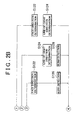
- FIG. 2A, 2B are flow charts showing processing procedures of the image processing (hereinafter, referred to as the "first image processing") performed, by the image processing apparatus 1.
- This processing, performed by the image processing ECU 40 is repeatedly performed in a predetermined cycle (100 ms, for example) from when the image processing ECU 40 is turned on to when the image processing ECU 40 is turned off.
- FIG. 3 is a diagram showing the processing timing and the processing time of each process of the first image processing.
- step S100 the data of a driver's face image that is picked up by the camera 10 is read. Subsequently, in step 5102, the read face image data is subjected to a filtering process.
- step S104 the position of the driver's face is determined based on the obtained face image data.
- the face position is determined by performing edge detection and pattern recognition in combination.
- step S106 the characteristic points in the face whose position is determined in step S104 are detected.
- the characteristic points of a face are the points that are positioned at the boundaries between the skin and each of the outer corners of the eyes, each of the inner corners of the eyes, each of the right and left nostrils, and each of the right and left corners of the mouth, for example, and therefore, are the points at which there is evident difference in the image data, such as brightness and color.
- step S108 the value of the counter CT whose value varies from 1 to 6 and that is used to perform the processes set for each unit cycle is incremented by one.
- the value of the counter CT is incremented by one every time the processing is performed, and, when the count of 6 is reached, the value of the counter CT is reset to zero (step S132 described later).
- step S110 it is determined whether the value of the counter CT is "1".
- the face direction determination step S122
- the line-of-sight direction determination step S124
- the face direction determination step The position of the center of the face (the line passing through the tip of the nose) and the positions of both sides of the face are detected from the obtained image data by using established methods, such as edge detection, in combination, and the face direction is calculated based on the positions of the center and both sides of the face.
- the line of sight of the driver is detected based on the characteristic points obtained in step S106. More specifically, the line of sight is determined using the change in the relative positions between the center of the iris of the eye and the characteristic points at the corners of the eye.
- the face direction and the line-of-sight direction are defined such that the direction that coincides with the forward direction of the host vehicle has the angle of zero, the direction on the right side of the forward direction has a positive angle, and the direction on the left side of the forward direction has a negative angle.
- the processing proceeds to step S112.
- step S112 it is determined whether the value of the counter CT is "2".
- the line-of-sight direction determination is as described above, and therefore description thereof will be omitted.
- the blink detection (step S126) the change in, of the characteristic points detected in step S106, the characteristic points related to the eyes at which a change is made due to sleepiness, that is, a blink, is detected.
- the processing proceeds to step S114.
- step S114 it is determined whether the value of the counter CT is "3".
- the face direction determination and the blink detection are as described above, and therefore description thereof will be omitted.
- the processing proceeds to step S116.
- step S116 it is determined whether the value of the counter CT is "4".
- the line-of-sight direction determination step S124
- the dozing determination step S128,
- the consciousness deterioration level determination step S130
- the line-of-sight direction determination is as described above, and therefore description thereof will be omitted.
- step S128 based on the line-of-sight direction determined in step S124 and the blink detected in step S126, it is determined that the driver is dozing when, for example, it is determined that the eyes of the driver have been closed for more than a predetermined period of time.
- step S130 based on the blink detected in step S126, it is determined whether the consciousness of the driver is deteriorated. More specifically, the focus is placed on the blink (in particular, successive blinks: a plurality of blinks that are performed at intervals shorter than the normal intervals of blinks), and, when successive blinks are detected, it is determined that the consciousness of the driver is deteriorated.
- the processing proceeds to step S118.
- step S118 it is determined whether the value of the counter CT is "5".
- the face direction determination step S122
- the line-of-sight direction determination step S124
- the blink detection step S126
- the face direction determination, the line-of-sight direction determination, and the blink detection are as described above, and therefore description thereof will be omitted.
- the processing proceeds to step S120.
- step S120 it is determined whether the value of the counter CT is "6".
- the blink detection, the dozing determination, and the consciousness deterioration level determination are as described above, and therefore description thereof will be omitted.
- the processing proceeds to step S134.
- step S134 after one of the above-described sets of processes is performed, the result thereof is output. Then, the processing is repeatedly performed in a predetermined unit cycle.
- this embodiment is configured not so that the plurality of processes (five processes in this embodiment) that constitute the image processing are all indiscriminately performed with the same priority, but so that the combination of the performed processes is set for each unit cycle (according to the value of the counter CT) in accordance with the priorities individually set for the processes, and the image processing is performed every fundamental cycle that is constituted of six unit cycles. Accordingly, it is possible to achieve the optimum process combination within the limits of the processing cycle (processing time) in consideration of the priorities of the processes. As a result, it is made possible to efficiently perform image processing involving a plurality of processes.
- the combination of the processes is set so that the processes performed in each unit cycle complete within a single unit cycle, and it is therefore possible to ensure real-time output of the image processing result.
- the priority of each process and the combination of the processes are predetermined, it is also possible to adopt a configuration in which the priority of each process and the combination of the processes are varied depending on the driving status of the vehicle and the status of the driver.
- FIG. 4 is a block diagram showing the configuration of the image processing apparatus 2.
- the components the same as or similar to those of the first embodiment are designated by the same reference characters.
- the image processing apparatus 2 differs from the above-described image processing apparatus 1 in further including a driving status detection means 20 that detects the driving status of the vehicle, and a driving environment sensing means 30 that senses the environment of the road on which the vehicle is running.
- the second embodiment differs from the above-described first embodiment in that an image processing ECU 41, which is a component of the image processing apparatus 2, sets the priority for each process based on the driving status of the vehicle that is detected by the driving status detection means 20 and/or the driving environment sensing means 30, and that the image processing ECU 41 selects, from the above-described plurality of processes, the processes that are performed for each unit cycle in accordance with the set priorities.
- Other components are the same as or similar to the corresponding ones of the above-described first embodiment, and therefore description thereof will be omitted.
- the driving status detection means 20 includes a steering angle sensor 21, an accelerator pedal operation amount sensor 22, a vehicle speed sensor 23, a lateral acceleration sensor 24, and a longitudinal acceleration sensor 25, for example.
- the steering angle sensor 21 is a sensor that detects the steering angle of a steering wheel, and outputs the detected value to the image processing ECU 41.
- the accelerator pedal operation amount sensor 22 is a sensor that detects the amount of operation of an accelerator pedal, and outputs the detected value to the image processing ECU 41.
- the vehicle speed sensor 23 is a sensor that detects the speed of the vehicle, and outputs the detected value to the image processing ECU 41.
- the lateral acceleration sensor 24 is a sensor that detects the lateral acceleration of the vehicle, and outputs the detected value to the image processing ECU 41.
- the driving environment sensing means 30 includes a preceding-vehicle speed/distance sensor 31 and a car navigation system 32.
- the preceding-vehicle speed/distance sensor 31 senses whether there is a preceding vehicle based on the radar data for the area ahead of the host vehicle provided by a radar, and, when there is a preceding vehicle, the preceding-vehicle speed/distance sensor 31 senses the speed of the preceding vehicle and the distance to the preceding vehicle and outputs the sensing result information to the image processing ECU 41.
- the car navigation system 32 is a system that, for example, detects the current position and the driving direction of the vehicle and provides guidance on the route to the destination, and outputs such data to the image processing ECU 41.
- the car navigation system 32 outputs information on the road around the current position to the image processing ECU 41.
- the road information includes traffic-jam information, traffic-signal information, the form of intersections, and the number of lanes, for example.
- the driving status detection means 20 and the driving environment sensing means 30 may be regarded as the driving status detection means of the invention.
- FIG. 5 is a flow chart showing a processing procedure of the image processing (hereinafter, referred to as the "second image processing") performed by the image processing apparatus 2.
- This processing performed by the image processing ECU 41, is repeatedly performed in a predetermined cycle (100 ms, for example) from when the image processing ECU 41 is turned on to when the image processing ECU 41 is turned off.
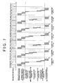
- FIGS. 6A to 6D are diagrams showing the processing timing and the processing time of each process in the second image processing.
- steps S200 to S206 are the same as the above-described steps S100 to S106, description thereof will be omitted.
- step S208 the detection results showing the driving status of the vehicle that are obtained by the driving status detection means 20 and the driving environment sensing means 30 are read.
- conditions of the driver are read. The conditions of the driver are determined based on the picked-up image of the driver.
- the camera 10 and the image processing ECU 41 may be regarded as the driver condition determination means of the invention.
- the kinetic status of the vehicle, driving environment, and the conditions of the driver are determined and classified based on the various data read in step S208.
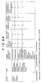
- An example of the classification is shown in FIGS. 6A to 6D .
- classes include "Kinetic Status of Vehicle", “Driving Environment 1", “Driving Environment 2", and “Conditions of Driver”.
- Under the class "Kinetic Status of Vehicle” there are items, such as “Driving at High Speed”, “Driving at Low Speed”, “Lateral Acceleration is High”, and “Longitudinal Acceleration is High”.
- Determination concerning the items “Driving at High Speed” and “Driving at Low Speed” is made based on the result of detection by the vehicle speed sensor 23, determination concerning the item “Lateral Acceleration is High” is made using the lateral acceleration sensor 24, and determination concerning the item “Longitudinal Acceleration is High” is made based on the result of detection by the longitudinal acceleration sensor 25 and the accelerator pedal operation amount sensor 22. Determination concerning the items “Jammed Road (no traffic signal)” and “Jammed Road (having traffic signals)” is made based on VICS (Vehicle Information and Communication System) information and map data provided by the car navigation system 32.
- VICS Vehicle Information and Communication System
- Determination concerning the item "Incidence of Direct Sunlight” is made based on the brightness of the face image data
- determination concerning the items “Night Driving” and “Commuting Time” is made based on the time data provided by the car navigation system 32
- determination concerning the items “Vehicles around Host Vehicle” and “Pedestrians” is made based on the result of detection by the preceding-vehicle speed/distance sensor 31.
- Determination concerning the items "Wearing Glasses”, “Wearing Sunglasses”, “Eyes are Covered with Hair”, and “Wearing Hat” is made based on the face image data, and determination concerning the items “Accustomed Road” and “First-Time Road” is made based on the vehicle path history data provided by the car navigation system 32.
- step S212 scheduling of the processes performed within each unit cycle is performed. More specifically, the priority of each process is set based on, for example, the kinetic status of the vehicle, driving environment, and the conditions of the drive that are determined and classified in step S210, and the processes that are performed within each unit cycle are selected and the combination is set in accordance with the set priorities.
- An example of the relations between the above-described items and the priorities of the processes face direction determination, line-of-sight direction determination, blink detection, dozing determination, and consciousness deterioration level determination is shown in FIGS. 6A to 6D .
- the priorities of the processes are "A”, “B”, “A”, “A” and “B”, respectively.
- the priorities of the processes satisfy "A” > "B” > "C”.
- a method of scheduling the processes will be described with respect to the case where it is determined that the conditions for the "Driving at High Speed” and “Lateral Acceleration is High” are satisfied with respect to the kinetic status of the vehicle, that the conditions for the "Tokyo Metropolitan Expressway” are satisfied with respect to the driving environment 1, that the conditions for the "Night Driving” and “Vehicles around Host vehicle” are satisfied with respect to the driving environment 2, and that the conditions for the "Wearing Glasses” are satisfied with respect to the conditions of the driver, by way of example.
- the priorities of the face direction determination process, the line-of-sight direction determination process, the blink detection process, the dozing determination process, and the consciousness deterioration level determination process are "A”, “B”, “A”, “A” and “B”, respectively.
- the priorities of the face direction determination process, the line-of-sight direction determination process, the blink detection process, the dozing determination process, and the consciousness deterioration level determination process are "B", "B", “B”, “C” and “C”, respectively.
- the priorities of the processes are read for each of the items "Driving on Tokyo Metropolitan Expressway", “Night Driving”, “Vehicles around Host Vehicle", and "Wearing Glasses”.
- the priorities of the items “Driving at High Speed”, “Lateral Acceleration is High”, “Driving on Tokyo Metropolitan Expressway”, “Night Driving”, “Vehicle around Host Vehicle”, and “Wearing Glasses” are “B", “B”, “A”, “B”, “A”, and “B”, respectively.
- the mean value is (2+2+4+2+4+2)/6 ⁇ 2.7.
- the priority of the "line-of-sight direction determination” process is determined to be “B”.
- the priorities of the "blink detection” process, the “dozing determination” process, and the “consciousness deterioration level determination” process are "A", "B", and “C”, respectively.
- the scheduling of the processes is performed based on the calculated priorities of the processes.
- An example of the scheduling method will be described.
- the combination (scheduling) of the processes adopted in the above-described first embodiment is set as a default.
- the rule for assignment according to the process priorities (A, B and C) is defined as follows: the occupation rate in each fundamental cycle (six unit cycles) is equal to or greater than 66% when the priority is "A", about 50% when the priority is "B”, and equal to or less than 30% when the priority is "C”.
- the processes are assigned to each of the six unit cycles so that the processes with the priority "A” are performed four times or more, the processes with the priority "B” are performed three times, and the processes with the priority "C” are performed two times (so that the higher the priority of the process is, the higher the occupation rate of the process is).
- the upper limit value of the computing power of the processor is 3 for the process with the priority "A", and 2 for the process with the priority "B".
- this value does not exceed the upper limit value of the computing power, and it is determined that there is no problem with the calculation cycle and the scheduling.
- step S214 the processes are performed according to the process schedule of each unit cycle set in step S212.
- Each of the processes of each unit cycle is performed in a similar way to that of the first embodiment (steps S108 to S132). The method is as described above, and therefore detailed description thereof will be omitted.
- step S216 the result of processing is output in step S216, and the processing temporarily exits. Then, the processing is repeatedly performed in a predetermined fundamental cycle.
- the priorities of the processes are set based on the kinetic status of the vehicle, the driving environment, and the conditions of the driver, and the processes that are performed are selected for each unit cycle in accordance with the set priorities, and then the scheduling is performed.
- the priorities of the processes are set based on the kinetic status of the vehicle, the driving environment, and the conditions of the driver, and the processes that are performed are selected for each unit cycle in accordance with the set priorities.
- the priorities of the processes are set based on the kinetic status of the vehicle, the driving environment, and the conditions of the driver, and the processes that are performed are selected for each unit cycle in accordance with the set priorities.
- a configuration may be adopted in which the calculation load is reduced by setting the priority with which the result of detection is adopted based on the difference in the reliability of blink detection between the right and left eyes, determining the priority regarding which of the right and left eyes should be subjected to the blink detection based on the direction of the face of a driver, and thus skipping the next calculation for the eye for which the above reliability is low or the eye for which the above priority is low, in the above-described second embodiment.
- a configuration may be adopted in which the calculation load is reduced by performing detection only for the left eye when the driver faces right, performing detection only for the right eye when the driver faces left, and skipping the line-of-sight direction determination process when the eyes are closed and therefore no blink is detected.
- the priorities of the processes are set with the image data of the face of a driver also taken into account, and it is therefore possible to set an optimum priority for each process, according to the image data of the individual face.
- the number of the unit cycles that constitute the fundamental cycle in which the image processing is performed is not limited to six. Further, the contents of the processes and the division of functions of the plurality of processes are not limited to those of the above-described embodiments.
- the various sensors which are components of the driving status detection means 20 and the driving environment sensing means 30 are not limited to those of the above-described embodiments. In place of or in addition to the above-described sensors, one or more different sensors may be used.
- a configuration may be adopted in which a process with a higher priority is performed using a highly accurate algorithm, whereas a process with a lower priority is performed using an algorithm with lower accuracy or is skipped.
- Some algorithms show high accuracy but take long time to complete processing; meanwhile, other algorithms show less accuracy but take less time to complete processing.
Abstract
Description
- The invention relates to an image processing apparatus and an image processing method.
- Japanese Patent Application Publication No.
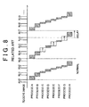
2003-15816 - In the systems, such as pre-crash safety systems, in which real-time output of the image processing results is required, a series of processes must be completed within a predetermined period of time. However, even when errors are not occurring, the processing time of each process in image processing is not constant, but varies depending on, for example, the branching conditions and other interrupt processes (in particular, multiple interruptions) (see
FIG. 8 ). Meanwhile, the importance and the required accuracy of a process vary depending on the process in many cases. Thus, also in view of the real-time processing and the required accuracy, it is difficult to say that it is efficient to indiscriminately perform all the processes.
The following prior art document teaches an autonomous driving system which schedules in real time different image processing routines to detect relevant visual information, such as a stop sign and stop light - G. Salgian et al. - "Visual Routines for Autonomous Driving", Sixth International Conference on Computer Vision, (ICCV'98), 4-7 Jan. 1998, pp. 876 - 882.
- N. Apostoloff et al. - "Vision In and Out of Vehicles: Integrated Driver and Road Scene Monitoring". Intl. Journal of Robotics Research, Vol. 23, No. 4-5, April-May 2004, pp. 513-538.
- The invention provides an image processing apparatus and an image processing method that more efficiently perform image processing involving a plurality of processes.
- An image processing apparatus according to a first aspect of the invention is an image processing apparatus that performs image processing in a fundamental cycle by performing a plurality of processes on data of an image picked up by a camera means, the apparatus including: a process setting means for constituting the fundamental cycle, in which a series of the image processes are performed, from a plurality of unit cycles, and for selecting, from the plurality of processes, the processes that are performed and setting a combination of the selected processes for each of the plurality of unit cycles constituting the fundamental cycle, in accordance with a priority of each of the plurality of processes; and a processing means for performing each of the processes in accordance with the combination set by the process setting means.
- The image processing apparatus according to the first aspect of the invention is configured not so that the plurality of processes that constitute the image processing are all indiscriminately performed with the same priority, but so that the combination of the performed processes is set for each unit cycle in accordance with the priorities individually set for the processes, and the image processing is performed every fundamental cycle that is constituted of a plurality of unit cycles. Accordingly, it is possible to achieve the optimum process combination within the limits of the processing cycle (processing time) in consideration of the priorities of the processes. As a result, it is made possible to efficiently perform image processing involving a plurality of processes. Such an image processing apparatus is capable of efficiently performing image processing. Thus, the image processing apparatus is useful especially when the available resources are limited, such as when used as an onboard image processing apparatus, and it is possible to obtain required information in real time.
- The "processes" mean those performed to obtain "various pieces of information" from image data. The "various pieces of information" include information concerning detection of an object, information concerning determination of conditions of the object, and information concerning determination made using such information, for example. By setting the priorities of the processes that are performed to obtain the "various pieces of information" from the image data, and setting the combination of the processes that are performed for each of the plurality of unit cycles in accordance with the priorities, it is possible to efficiently perform the image processing.
- The process setting means may select, from the plurality of processes, the processes that are performed and set the combination of the selected processes for each of the plurality of unit cycles so that the higher the priority of the process is, the higher the occupation rate of the process in the fundamental cycle is. When the occupation rate in the fundamental cycle is set so that the higher the priority of the process is, the higher the occupation rate of the process in the fundamental cycle is in this way, the number of times such a process(es) are performed and the processing time used for such a process(es) are increased, which makes it possible to efficiently perform image processing processes.
- The process setting means may set the combination of the processes in consideration of processing time and required accuracy of each of the processes and/or the required number of times the processes are performed relative to the number of times the picked-up image is received within the fundamental cycle.
- With this configuration, it is possible to set the combination of the processes in consideration of the importance of each process, the required frequency of updating the processing result, the processing load, and the required accuracy, which are criteria used in setting the priorities, so that it is possible to adjust the proportion of the processing load of each process to the whole processing load, according to the priorities of the processes.
- The process setting means may set the combination of the processes so that the processes performed every unit cycle are completed within a single unit cycle.
- In this case, the combination of the processes is set so that the processes complete within a unit cycle, and it is therefore possible to ensure real-time output of the image processing result.
- In this case, the process setting means may set the combination of the processes so that the sum of the processing time of the processes that are performed within each unit cycle is less than the duration of a single unit cycle.
- The process setting means may change the priorities of the processes, and select, from the plurality of processes, the processes that are performed for each of the unit cycles in accordance with the changed priorities. When the priorities are changed in this way, it is possible to efficiently perform the image processing in response to the importance and the required accuracy of the process with respect to the processes that depend on the changes in conditions.
- The image processing apparatus may further include a driving status detection means for detecting driving status of a vehicle, the camera means may be installed in the vehicle, and the process setting means may set the priority of each of the processes based on the driving status of the vehicle detected by the driving status detection means, and select, from the plurality of processes, the processes that are performed for each of the unit cycles in accordance with the set priorities.
- When the image processing is performed on the data of the image picked up by the camera means installed in the vehicle, the above-described priority and processing load of each process are affected by the driving status of the vehicle, such as the kinetic status of the vehicle and the driving environment. According to the image processing apparatus according to the first aspect of the invention, the priorities of the processes are set based on the driving status of the vehicle, and the processes that are performed are selected for each unit cycle in accordance with the set priorities. Thus, it is possible to set an appropriate priority for each process according to the picked-up image, and it is therefore possible to select the performed processes and set a combination of the processes for each unit cycle in accordance with the priorities. As a result, it is possible to more efficiently perform image processing involving a plurality of processes on the data of the image that is picked up by the camera means installed in the vehicle.
- The image processing apparatus may further include a driver condition determination means for determining conditions of a driver, the image that is picked up by the camera means may be a face image of the driver; and the process setting means may set the priority of each of the processes based on the conditions of the driver determined by the driver condition determination means, and select, from the plurality of processes, the processes that are performed for each of the unit cycles in accordance with the set priorities.
- When the image processing is performed on the data of the face image of the driver, the above-described priority and processing load of each process are affected by the conditions of the driver, such as the motion, the external features, and the personal features of the driver. According to the image processing apparatus according to the first aspect of the invention, the priorities of the processes are set based on the conditions of the driver, and the processes that are performed are selected for each unit cycle in accordance with the set priorities. Thus, it is possible to set an appropriate priority for each process according to the face image of the driver, and it is therefore possible to select the performed processes and set a combination of the processes for each unit cycle in accordance with the priorities. As a result, it is made possible to more efficiently perform image processing involving a plurality of processes on the image data of the face of the driver.
- The process setting means may also take into account the face image of the driver picked up by the camera means in setting the priority of each of the processes.
- When the image processing is performed on the data of the face image of the driver, the above-described priority and processing load of each process are affected by the face image of the driver, that is, the face direction, for example. According to the image processing apparatus according to the first aspect of the invention, the priorities of the processes are set with the image data of the face of a driver also taken into account, and it is therefore possible to set an optimum priority for each process, according to the image data of the individual face. As a result, it is made possible to more efficiently perform image processing involving a plurality of processes on the image data of the face of the driver.
- According to the first aspect of the invention, the image processing apparatus that performs image processing every fundamental cycle by performing a plurality of processes on data of the received image is configured so that the processes that are performed are selected from the plurality of processes and a combination of such processes is set for each of the plurality of unit cycles constituting the fundamental cycle in accordance with a priority of each of the plurality of processes. Thus, it is made possible to more efficiently perform image processing involving a plurality of processes.
- In an image processing method according to a second aspect of the invention, image processing is performed in a fundamental cycle, in which a plurality of processes are performed on data of an image picked up by a camera means. The image processing method includes: selecting, from the plurality of processes, the processes that are performed and setting a combination of the selected processes for each of a plurality of unit cycles constituting the fundamental cycle, in accordance with a priority of each of the plurality of processes; and performing each of the processes in accordance with the set combination of the processes.
- According to the second aspect of the invention, the image processing apparatus that performs image processing every fundamental cycle by performing a plurality of processes on data of the received image selects, from the plurality of processes, the processes that are performed and sets a combination of such processes for each of the unit cycles constituting the fundamental cycle in accordance with the priorities of the processes. Thus, it is made possible to more efficiently perform image processing involving a plurality of processes.
- The foregoing and further features and advantages of the invention will become apparent from the following description of example embodiments with reference to the accompanying drawings, wherein like numerals are used to represent like elements, and wherein:
-
FIG. 1 is a block diagram showing a configuration of an image processing apparatus according to a first embodiment; -
FIG. 2A and2B are flow charts showing processing procedures of image processing (first image processing) performed by the image processing apparatus according to the first embodiment; -
FIG. 3 is a diagram showing processing timing and processing time of each process of the first image processing; -
FIG. 4 is a block diagram showing a configuration of an image processing apparatus according to a second embodiment; -
FIG. 5 is a flow chart showing a processing procedure of image processing (second image processing) performed by the image processing apparatus according to the second embodiment; -
FIGS. 6A to 6D are diagrams showing an example of kinetic status of a vehicle, driving environment, conditions of a driver, and priorities of processes; -
FIG. 7 is a diagram showing processing timing and processing time of each process of the second image processing; and -
FIG. 8 is a diagram showing processing timing and processing time of each process of conventional image processing. - Example embodiments of the invention will be described in detail below with reference to drawings. In the drawings, the same or corresponding elements are designated by the same reference characters. The description will be given of a case where apparatuses according to embodiments of the invention are installed in a vehicle and determine sleepiness of a driver based on a picked-up face image of the driver, by way of example.
- First, with reference to
FIG. 1 , a configuration of animage processing apparatus 1 according to a first embodiment will be described.FIG. 1 is a block diagram showing the configuration of theimage processing apparatus 1. - The
image processing apparatus 1 is installed in a vehicle. Theimage processing apparatus 1 detects the direction of a driver's face, a driver's line-of-sight direction, and a driver's blink by performing image processing on the data of the picked-up face image of the driver, and determines whether the driver is dozing and the level of deterioration in consciousness of the driver based on the result of the detection. For this purpose, theimage processing apparatus 1 includes acamera 10 for picking up a face image of the driver, and an image processing ECU (Electronic Control Unit) 40. - The
camera 10 is used to obtain an image of the area including the face of the driver. Thecamera 10 is installed in an instrument panel or a steering column, directed toward the face of the driver. Thecamera 10 picks up an image every predetermined period of time (1/30 second, for example), and sends the image data of each frame to theimage processing ECU 40 as a video signal. In order to obtain a clear image, the apparatus may include an LED light. - The
image processing ECU 40 includes: a microprocessor that performs calculation; a ROM that stores programs for causing the microprocessor to perform various processes; a RAM that stores various data, such as results of calculation; and a backup RAM whose memory content is maintained by a battery, etc. - The
image processing ECU 40 reads the data of a driver's face image that is picked up by thecamera 10, and performs the driver's dozing determination and/or the driver's consciousness deterioration level determination by repeatedly performing on the read data in a fundamental cycle (600 ms, for example) image processing (initializing process and image receiving process, filtering process and characteristic-point detection process, face direction determination process, line-of-sight direction determination process, blink detection process, dozing determination process, consciousness deterioration level determination process, and output process and diagnosis process). It should be noted that one process may be performed a plurality of times within the fundamental cycle. - When this is performed, from the plurality of processes (face direction determination process, line-of-sight direction determination process, blink detection process, dozing determination process, and consciousness deterioration level determination process), which are involved in the image processing, the
image processing ECU 40 selects the processes that are performed and sets a combination of the processes for each of the six unit cycles (100 ms, for example) that constitute the fundamental cycle, in accordance with the priorities of the processes, and performs each of the processes according to the combination. Theimage processing ECU 40 sets the combination of the processes so that the processes performed every unit cycle are completed within a single unit cycle. Specifically, the combination of the processes is set so that the sum of the processing time of the processes that are performed within each unit cycle is less than the duration of a single unit cycle. Thus, theimage processing ECU 40 may be regarded as the process setting means and the processing means of the invention. The initializing process and the image receiving process, the filtering process and the characteristic-point detection process, and the output process and the diagnosis process are performed every unit cycle. - Next, operation of the
image processing apparatus 1 will be described with reference toFIGS. 2A ,2B and3 .FIG. 2A, 2B are flow charts showing processing procedures of the image processing (hereinafter, referred to as the "first image processing") performed, by theimage processing apparatus 1. This processing, performed by theimage processing ECU 40, is repeatedly performed in a predetermined cycle (100 ms, for example) from when theimage processing ECU 40 is turned on to when theimage processing ECU 40 is turned off.FIG. 3 is a diagram showing the processing timing and the processing time of each process of the first image processing. - In step S100, the data of a driver's face image that is picked up by the
camera 10 is read. Subsequently, in step 5102, the read face image data is subjected to a filtering process. - Subsequently, in step S104, the position of the driver's face is determined based on the obtained face image data. The face position is determined by performing edge detection and pattern recognition in combination.
- Next, in step S106, the characteristic points in the face whose position is determined in step S104 are detected. The characteristic points of a face are the points that are positioned at the boundaries between the skin and each of the outer corners of the eyes, each of the inner corners of the eyes, each of the right and left nostrils, and each of the right and left corners of the mouth, for example, and therefore, are the points at which there is evident difference in the image data, such as brightness and color.
- Subsequently, in step S108, the value of the counter CT whose value varies from 1 to 6 and that is used to perform the processes set for each unit cycle is incremented by one. Thus, the value of the counter CT is incremented by one every time the processing is performed, and, when the count of 6 is reached, the value of the counter CT is reset to zero (step S132 described later).
- In subsequent step S110, it is determined whether the value of the counter CT is "1". When the value of the counter CT is "1", the face direction determination (step S122) and the line-of-sight direction determination (step S124) are performed, and the processing then proceeds to step S134 (see the case of "counter CT=1" in
FIG. 3 ). In the face direction determination (step The position of the center of the face (the line passing through the tip of the nose) and the positions of both sides of the face are detected from the obtained image data by using established methods, such as edge detection, in combination, and the face direction is calculated based on the positions of the center and both sides of the face. In the line-of-sight direction determination (step S124), the line of sight of the driver is detected based on the characteristic points obtained in step S106. More specifically, the line of sight is determined using the change in the relative positions between the center of the iris of the eye and the characteristic points at the corners of the eye. It should be noted that the face direction and the line-of-sight direction are defined such that the direction that coincides with the forward direction of the host vehicle has the angle of zero, the direction on the right side of the forward direction has a positive angle, and the direction on the left side of the forward direction has a negative angle. On the other hand, when the value of the counter CT is not "1", the processing proceeds to step S112. - In step S112, it is determined whether the value of the counter CT is "2". When the value of the counter CT is "2", the line-of-sight determination (step S124) and the blink detection (step S126) are performed, and the processing then proceeds to step S134 (see the case of "counter CT=2" in
FIG. 3 ). The line-of-sight direction determination is as described above, and therefore description thereof will be omitted. In the blink detection (step S126), the change in, of the characteristic points detected in step S106, the characteristic points related to the eyes at which a change is made due to sleepiness, that is, a blink, is detected. When the value of the counter CT is not "2", the processing proceeds to step S114. - In step S114, it is determined whether the value of the counter CT is "3". When the value of the counter CT is "3", the face direction determination (S122) and the blink detection (step S126) are performed, and the processing then proceeds to step S134 (see the case of "counter CT=3" in
FIG. 3 ). The face direction determination and the blink detection are as described above, and therefore description thereof will be omitted. When the value of the counter CT is not "3", the processing proceeds to step S116. - In step S116, it is determined whether the value of the counter CT is "4". When the value of the counter CT is "4", the line-of-sight direction determination (step S124), the dozing determination (step S128), and the consciousness deterioration level determination (step S130) are performed, and the processing then proceeds to step S134 (see the case of "counter CT=4" in
FIG. 3 ). The line-of-sight direction determination is as described above, and therefore description thereof will be omitted. In the dozing determination (step S128), based on the line-of-sight direction determined in step S124 and the blink detected in step S126, it is determined that the driver is dozing when, for example, it is determined that the eyes of the driver have been closed for more than a predetermined period of time. In the consciousness deterioration level determination (step S130), based on the blink detected in step S126, it is determined whether the consciousness of the driver is deteriorated. More specifically, the focus is placed on the blink (in particular, successive blinks: a plurality of blinks that are performed at intervals shorter than the normal intervals of blinks), and, when successive blinks are detected, it is determined that the consciousness of the driver is deteriorated. When the value of the counter CT is not "4", the processing proceeds to step S118. - In step S118, it is determined whether the value of the counter CT is "5". When the value of the counter CT is "5", the face direction determination (step S122), the line-of-sight direction determination (step S124), and the blink detection (step S126) are performed, and the processing then proceeds to step S134 (see the case of "counter CT=5" in
FIG. 3 ). The face direction determination, the line-of-sight direction determination, and the blink detection are as described above, and therefore description thereof will be omitted. When the value of the counter CT is not "5", the processing proceeds to step S120. - In step S120, it is determined whether the value of the counter CT is "6". When the value of the counter CT is "6", the blink detection (step S126), the dozing determination (step S128), and the consciousness deterioration level determination (step S130) are performed, and the value of the counter CT is then reset to zero (see the case of "counter CT=6" in
FIG. 3 ). Thereafter, the processing proceeds to step S134. The blink detection, the dozing determination, and the consciousness deterioration level determination are as described above, and therefore description thereof will be omitted. When the value of the counter CT is not "6", the processing proceeds to step S134. - In step S134, after one of the above-described sets of processes is performed, the result thereof is output. Then, the processing is repeatedly performed in a predetermined unit cycle.
- According to this embodiment, each step is performed as described above, so that: the face direction determination and the line-of-sight direction determination are performed in the case of "counter CT=1"; the line-of-sight direction determination and the blink detection are performed in the case of "counter CT=2", and the face direction determination and the blink detection are performed in the case of "counter CT=3", as shown in
FIG 3 . The line-of-sight direction determination, the dozing determination, and the consciousness deterioration level determination are performed in the case of "counter CT=4", the face direction determination, the line-of-sight direction determination, and the blink detection are performed in the case of "counter CT=5", and the blink detection, the dozing determination, and the consciousness deterioration level determination are performed in the case of "counter CT=6". - Thus, this embodiment is configured not so that the plurality of processes (five processes in this embodiment) that constitute the image processing are all indiscriminately performed with the same priority, but so that the combination of the performed processes is set for each unit cycle (according to the value of the counter CT) in accordance with the priorities individually set for the processes, and the image processing is performed every fundamental cycle that is constituted of six unit cycles. Accordingly, it is possible to achieve the optimum process combination within the limits of the processing cycle (processing time) in consideration of the priorities of the processes. As a result, it is made possible to efficiently perform image processing involving a plurality of processes.
- According to this embodiment, it is possible to set the combination of the processes in advance in consideration of the importance of each process, the required frequency of updating the processing result, the processing load and the required accuracy, which are criteria used in setting the priorities, so that it is possible to adjust the proportion of the processing load of each process to the whole processing load, according to the priorities of the processes.
- In addition, according to this embodiment, the combination of the processes is set so that the processes performed in each unit cycle complete within a single unit cycle, and it is therefore possible to ensure real-time output of the image processing result.
- Although, in the above-described first embodiment, the priority of each process and the combination of the processes are predetermined, it is also possible to adopt a configuration in which the priority of each process and the combination of the processes are varied depending on the driving status of the vehicle and the status of the driver.
- Next, with reference to
FIG. 4 , a configuration of animage processing apparatus 2 according to a second embodiment will be described.FIG 4 is a block diagram showing the configuration of theimage processing apparatus 2. InFIG. 4 , the components the same as or similar to those of the first embodiment are designated by the same reference characters. - The
image processing apparatus 2 differs from the above-describedimage processing apparatus 1 in further including a driving status detection means 20 that detects the driving status of the vehicle, and a driving environment sensing means 30 that senses the environment of the road on which the vehicle is running. - In addition, the second embodiment differs from the above-described first embodiment in that an
image processing ECU 41, which is a component of theimage processing apparatus 2, sets the priority for each process based on the driving status of the vehicle that is detected by the driving status detection means 20 and/or the driving environment sensing means 30, and that theimage processing ECU 41 selects, from the above-described plurality of processes, the processes that are performed for each unit cycle in accordance with the set priorities. Other components are the same as or similar to the corresponding ones of the above-described first embodiment, and therefore description thereof will be omitted. - The driving status detection means 20 includes a
steering angle sensor 21, an accelerator pedaloperation amount sensor 22, avehicle speed sensor 23, alateral acceleration sensor 24, and alongitudinal acceleration sensor 25, for example. Thesteering angle sensor 21 is a sensor that detects the steering angle of a steering wheel, and outputs the detected value to theimage processing ECU 41. The accelerator pedaloperation amount sensor 22 is a sensor that detects the amount of operation of an accelerator pedal, and outputs the detected value to theimage processing ECU 41. Thevehicle speed sensor 23 is a sensor that detects the speed of the vehicle, and outputs the detected value to theimage processing ECU 41. Thelateral acceleration sensor 24 is a sensor that detects the lateral acceleration of the vehicle, and outputs the detected value to theimage processing ECU 41. - The driving environment sensing means 30 includes a preceding-vehicle speed/
distance sensor 31 and acar navigation system 32. The preceding-vehicle speed/distance sensor 31 senses whether there is a preceding vehicle based on the radar data for the area ahead of the host vehicle provided by a radar, and, when there is a preceding vehicle, the preceding-vehicle speed/distance sensor 31 senses the speed of the preceding vehicle and the distance to the preceding vehicle and outputs the sensing result information to theimage processing ECU 41. Thecar navigation system 32 is a system that, for example, detects the current position and the driving direction of the vehicle and provides guidance on the route to the destination, and outputs such data to theimage processing ECU 41. In addition, thecar navigation system 32 outputs information on the road around the current position to theimage processing ECU 41. The road information includes traffic-jam information, traffic-signal information, the form of intersections, and the number of lanes, for example. As can be seen from this description, the driving status detection means 20 and the driving environment sensing means 30 may be regarded as the driving status detection means of the invention. - Next, operation of the
image processing apparatus 2 will be described with reference toFIGS. 5 and6A to 6D .FIG. 5 is a flow chart showing a processing procedure of the image processing (hereinafter, referred to as the "second image processing") performed by theimage processing apparatus 2. This processing, performed by theimage processing ECU 41, is repeatedly performed in a predetermined cycle (100 ms, for example) from when theimage processing ECU 41 is turned on to when theimage processing ECU 41 is turned off.FIGS. 6A to 6D are diagrams showing the processing timing and the processing time of each process in the second image processing. - Because steps S200 to S206 are the same as the above-described steps S100 to S106, description thereof will be omitted.
- Subsequently, in step S208, the detection results showing the driving status of the vehicle that are obtained by the driving status detection means 20 and the driving environment sensing means 30 are read. In addition, conditions of the driver are read. The conditions of the driver are determined based on the picked-up image of the driver. In this case, the
camera 10 and theimage processing ECU 41 may be regarded as the driver condition determination means of the invention. - In the subsequent step S210, the kinetic status of the vehicle, driving environment, and the conditions of the driver are determined and classified based on the various data read in step S208. An example of the classification is shown in
FIGS. 6A to 6D . As shown inFIGS. 6A to 6D , classes include "Kinetic Status of Vehicle", "DrivingEnvironment 1", "DrivingEnvironment 2", and "Conditions of Driver". Under the class "Kinetic Status of Vehicle", there are items, such as "Driving at High Speed", "Driving at Low Speed", "Lateral Acceleration is High", and "Longitudinal Acceleration is High". Under the class "DrivingEnvironment 1", there are items, such as "Jammed Road (no traffic signal)", "Jammed Road (having traffic signals)", "Mountain Road", "Straight Road", "Narrow Road/Residential Street", "multiline Road", "Driving on High Speed Way", "Driving on Tokyo Metropolitan Expressway", and "Toll Road/Motor Vehicle Road". Under the class "DrivingEnvironment 2", there are items, such as "Incidence of Direct Sunlight", "Night Driving", "Commuting Time", "Vehicles around Host Vehicle", and "Pedestrians". Under the class "Conditions of Driver", there are items, such as "Wearing Glasses", "Wearing Sunglasses", "Eyes are Covered with Hair", "Wearing Hat", "Accustomed Road", and "First-Time. Road". - Determination concerning the items "Driving at High Speed" and "Driving at Low Speed" is made based on the result of detection by the
vehicle speed sensor 23, determination concerning the item "Lateral Acceleration is High" is made using thelateral acceleration sensor 24, and determination concerning the item "Longitudinal Acceleration is High" is made based on the result of detection by thelongitudinal acceleration sensor 25 and the accelerator pedaloperation amount sensor 22. Determination concerning the items "Jammed Road (no traffic signal)" and "Jammed Road (having traffic signals)" is made based on VICS (Vehicle Information and Communication System) information and map data provided by thecar navigation system 32. Determination concerning the items "Mountain Road", "Straight Road", "Narrow Road/Residential Street", "Multilane Road", "Driving on High Way", "Driving on Tokyo Metropolitan Expressway", and "Toll Road/Motor Vehicle Road" is made based on the map data provided by thecar navigation system 32. Determination concerning the item "Incidence of Direct Sunlight" is made based on the brightness of the face image data, determination concerning the items "Night Driving" and "Commuting Time" is made based on the time data provided by thecar navigation system 32, and determination concerning the items "Vehicles around Host Vehicle" and "Pedestrians" is made based on the result of detection by the preceding-vehicle speed/distance sensor 31. Determination concerning the items "Wearing Glasses", "Wearing Sunglasses", "Eyes are Covered with Hair", and "Wearing Hat" is made based on the face image data, and determination concerning the items "Accustomed Road" and "First-Time Road" is made based on the vehicle path history data provided by thecar navigation system 32. - Subsequently, in step S212, scheduling of the processes performed within each unit cycle is performed. More specifically, the priority of each process is set based on, for example, the kinetic status of the vehicle, driving environment, and the conditions of the drive that are determined and classified in step S210, and the processes that are performed within each unit cycle are selected and the combination is set in accordance with the set priorities. An example of the relations between the above-described items and the priorities of the processes (face direction determination, line-of-sight direction determination, blink detection, dozing determination, and consciousness deterioration level determination) is shown in
FIGS. 6A to 6D . For example, when it is determined that the vehicle is in the "Driving at High Speed" state, the priorities of the processes, the face direction determination, the line-of-sight direction determination, the blink detection, the dozing determination, and the consciousness deterioration level determination, are "A", "B", "A", "A" and "B", respectively. InFIGS. 6A to 6D , the priorities of the processes satisfy "A" > "B" > "C". - A method of scheduling the processes will be described with respect to the case where it is determined that the conditions for the "Driving at High Speed" and "Lateral Acceleration is High" are satisfied with respect to the kinetic status of the vehicle, that the conditions for the "Tokyo Metropolitan Expressway" are satisfied with respect to the driving
environment 1, that the conditions for the "Night Driving" and "Vehicles around Host vehicle" are satisfied with respect to the drivingenvironment 2, and that the conditions for the "Wearing Glasses" are satisfied with respect to the conditions of the driver, by way of example. - As described above, when it is determined that the vehicle is in the "Driving at High Speed" state, the priorities of the face direction determination process, the line-of-sight direction determination process, the blink detection process, the dozing determination process, and the consciousness deterioration level determination process, are "A", "B", "A", "A" and "B", respectively. Similarly, when it is determined that the vehicle is in the "Lateral Acceleration is High" state, the priorities of the face direction determination process, the line-of-sight direction determination process, the blink detection process, the dozing determination process, and the consciousness deterioration level determination process, are "B", "B", "B", "C" and "C", respectively. Similarly, the priorities of the processes are read for each of the items "Driving on Tokyo Metropolitan Expressway", "Night Driving", "Vehicles around Host Vehicle", and "Wearing Glasses".
- Next, the priority of each process in the case where the conditions for the items "Driving at High Speed", "Lateral Acceleration is High", "Driving on Tokyo Metropolitan Expressway", "Night Driving", "Vehicles around Host Vehicle", and "Wearing Glasses" are satisfied is determined. More specifically, because, with respect to the "face direction determination", for example, the priorities of the items "Driving at High Speed", "Lateral Acceleration is High", "Driving on Tokyo Metropolitan Expressway", "Night Driving", "Vehicles around Host Vehicle", and "Wearing Glasses" are "A", "B", "A", "A", "A", and "A", respectively, the calculation of the mean value, in which it is assumed that the points of A, B and C are 4, 2 and 1, respectively, results in (4+2+4+4+4+4+)/6≈3.7. When it is assumed that the priority of the process of which the mean value is equal to or greater than 3 is "A", that the priority of the process of which the mean value is equal to or greater than 2 and less than 3 is "B", and that the priority of the process of which the mean value is less than 2 is "C", the priority of the "face direction, determination" process is determined to be "A".
- Similarly, with respect to the "line-of-sight direction determination", for example, the priorities of the items "Driving at High Speed", "Lateral Acceleration is High", "Driving on Tokyo Metropolitan Expressway", "Night Driving", "Vehicle around Host Vehicle", and "Wearing Glasses" are "B", "B", "A", "B", "A", and "B", respectively. Thus, the mean value is (2+2+4+2+4+2)/6≈2.7. Thus, the priority of the "line-of-sight direction determination" process is determined to be "B". When the priorities of the processes are determined similarly, the priorities of the "blink detection" process, the "dozing determination" process, and the "consciousness deterioration level determination" process are "A", "B", and "C", respectively.
- The scheduling of the processes is performed based on the calculated priorities of the processes. An example of the scheduling method will be described. The combination (scheduling) of the processes adopted in the above-described first embodiment is set as a default. On top of that, the rule for assignment according to the process priorities (A, B and C) is defined as follows: the occupation rate in each fundamental cycle (six unit cycles) is equal to or greater than 66% when the priority is "A", about 50% when the priority is "B", and equal to or less than 30% when the priority is "C". The processes are assigned to each of the six unit cycles so that the processes with the priority "A" are performed four times or more, the processes with the priority "B" are performed three times, and the processes with the priority "C" are performed two times (so that the higher the priority of the process is, the higher the occupation rate of the process is).
- In this embodiment, the upper limit value of the computing power of the processor is 3 for the process with the priority "A", and 2 for the process with the priority "B". In this case, because of the calculation result, 3*66(%)+2*50(%)=3*(4/6)+2*(3/6)=3, the processes, each having one of the priorities "A", "B", and "C", are assigned so that this value is not exceeded. In the case of this embodiment, the priorities of the "face direction determination" process, the "line-of-sight direction determination" process, the "blink detection" process, the "dozing determination" process, and the "consciousness deterioration level determination" process are "A", "B", "A", "B", and "C", respectively, and the mean value is therefore calculated as follows: 2*(4/6)+2*(3/6)+1*(2/6)=2.7. Thus, because this value does not exceed the upper limit value of the computing power, and it is determined that there is no problem with the calculation cycle and the scheduling.
- Subsequently, in step S214, the processes are performed according to the process schedule of each unit cycle set in step S212. Each of the processes of each unit cycle is performed in a similar way to that of the first embodiment (steps S108 to S132). The method is as described above, and therefore detailed description thereof will be omitted.
- Next, the result of processing is output in step S216, and the processing temporarily exits. Then, the processing is repeatedly performed in a predetermined fundamental cycle.
- According to this embodiment, the priorities of the processes are set based on the kinetic status of the vehicle, the driving environment, and the conditions of the driver, and the processes that are performed are selected for each unit cycle in accordance with the set priorities, and then the scheduling is performed. The processes are performed in accordance with the process schedule, and as a result, as shown in
FIG. 7 , the face direction determination, the dozing determination, and the consciousness deterioration level determination are performed in the case of "counter CT=1"; the face direction determination, the line-of-sight direction determination, and the blink detection are performed in the case of "counter CT=2"; and the blink detection and the dozing determination are performed in the case of "counter CT=3". The face direction determination, the line-of-sight direction determination, and the consciousness deterioration level determination are performed in the case of "counter CT=4", the face direction determination and the line-of-sight direction determination are performed in the case of "counter CT=5", and the face direction determination, the dozing determination, and the consciousness deterioration level determination are performed in the case of "counter CT=6". - According to this embodiment, the priorities of the processes are set based on the kinetic status of the vehicle, the driving environment, and the conditions of the driver, and the processes that are performed are selected for each unit cycle in accordance with the set priorities. Thus, it is possible to set an appropriate priority for each process according to the picked-up image, and it is therefore possible to select the performed processes for each unit cycle in accordance with the priorities to accomplish the scheduling. As a result, it is possible to more efficiently perform image processing involving a plurality of processes on the data of the face image of the driver that is picked up by the
camera 10 installed in the vehicle. - In addition, a configuration may be adopted in which the calculation load is reduced by setting the priority with which the result of detection is adopted based on the difference in the reliability of blink detection between the right and left eyes, determining the priority regarding which of the right and left eyes should be subjected to the blink detection based on the direction of the face of a driver, and thus skipping the next calculation for the eye for which the above reliability is low or the eye for which the above priority is low, in the above-described second embodiment.
- When the positions of right and left eyelids are detected when the driver faces the front, a case can occur in which the accuracy of detection for one of the eyelids is inferior to the accuracy of detection for the other eyelid, depending on the light conditions. A configuration may be adopted in which, in such a case, only the data concerning the blink of the eyelid of the higher reliability is used, and the blink of the other eyelid is assumed to be the same as that of the former eyelid to skip the calculation.
- A configuration may be adopted in which the calculation load is reduced by performing detection only for the left eye when the driver faces right, performing detection only for the right eye when the driver faces left, and skipping the line-of-sight direction determination process when the eyes are closed and therefore no blink is detected.
- In this way, the priorities of the processes are set with the image data of the face of a driver also taken into account, and it is therefore possible to set an optimum priority for each process, according to the image data of the individual face. As a result, it is made possible to efficiently perform image processing involving a plurality of processes on the image data of the face of the driver.
- Although the embodiments of the invention have been described, the invention is not limited to the above-described embodiments, and various modifications can be made. In the description of the above-described embodiments, a case is described by way of example in which the image processing apparatus is installed in a vehicle and sleepiness of a driver is determined based on the data of the picked-up driver's face image. However, needless to say, the scope of the application of the image processing apparatus according to the invention is not limited to these embodiments.
- The number of the unit cycles that constitute the fundamental cycle in which the image processing is performed is not limited to six. Further, the contents of the processes and the division of functions of the plurality of processes are not limited to those of the above-described embodiments.
- The various sensors, which are components of the driving status detection means 20 and the driving environment sensing means 30 are not limited to those of the above-described embodiments. In place of or in addition to the above-described sensors, one or more different sensors may be used.
- In the above-described embodiment, in accordance with the priorities of the processes, the higher the priority of the process is, the greater the number of times the process is performed (processing time) in each unit cycle is. However, a configuration may be adopted in which a process with a higher priority is performed using a highly accurate algorithm, whereas a process with a lower priority is performed using an algorithm with lower accuracy or is skipped.
- By preparing a plurality of algorithms with different processing accuracies (operational densities) for each process, and assigning processing resources (processing power) in accordance with the priorities, it is made possible to control the processing load in accordance with the priorities. In addition, using algorithms with low accuracy means that low-load algorithms are used.
- Some algorithms show high accuracy but take long time to complete processing; meanwhile, other algorithms show less accuracy but take less time to complete processing. By setting the priorities based on the driving status of the vehicle and the conditions of the driver and selecting algorithms in accordance with the priorities, it is possible to efficiently perform image processing.
Claims (10)
- An image processing apparatus that performs image processing every fundamental cycle by performing a plurality of processes (S122 to S130) on data of an image picked up by camera means (10), the apparatus being characterized by comprising:process setting means (40) for constituting the fundamental cycle, in which a series of the image processes are performed, from a plurality of unit cycles, and for selecting,from the plurality of processes (S122 to S 130), the processes that are performed andsetting a combination of the selected processes for each of the plurality of unit cycles constituting the fundamental cycle, in accordance with a priority of each of the plurality of processes (S 122 to S130); andprocessing means (40) for performing each of the processes in accordance with the combination set by the process setting means, wherein:a value of a counter (CT) corresponding to an order and a combination of the image processing to be performed is set for each of the plurality of unit cycles; and the processing means (40) performs in a unit cycle each of the selected processes for each of the plurality of unit cycles sequentially in accordance with the priority and the set value of the counter (CT), said apparatus further comprising driving status detection means (20) for detecting driving status of a vehicle and driver condition determination means (41) for determining conditions of a driver, wherein:the image that is picked up by the camera means (10) is a face image of the driver and wherein the camera (10) means is installed in the vehicle; andthe process setting means (41) sets the priority of each of the processes based on the driving status of the vehicle detected by the driving status detection means (20) and based on the conditions of the driver determined by the driver condition determination means (41), and selects, from the plurality of processes, the processes that are performed for each of the unit cycles, in accordance with the set priorities.
- The image processing apparatus according to claim 1, wherein the process setting means (40) selects, from the plurality of processes (S122 to S130), the processes that are performed and sets the combination of the selected processes for each of the plurality of unit cycles so that the higher the priority of the process is, the higher an occupation rate of the process in the fundamental cycle is.
- The image processing apparatus according to claim 1 or 2, wherein the process setting means (40) sets the combination of the processes in consideration of processing time and required accuracy of each of the processes and/or a required number of times the processes are performed relative to a number of times the picked-up image is received within the fundamental cycle.
- The image processing apparatus according to any one of claims 1 to 3, wherein the process setting means (40) sets the combination of the processes so that the processes that are performed every unit cycle are completed within the unit cycle.
- The image processing apparatus according to claim 4, wherein the process setting means (40) sets the combination of the processes so that a sum of processing time of the processes that are performed every unit cycle is less than a duration of the unit cycle.
- The image processing apparatus according to any one of claims 1 to 5, wherein the process setting means (40) changes the priorities of the processes, and selects, from the plurality of processes, the processes that are performed for each of the unit cycles in accordance with the changed priorities.
- The image processing apparatus according to claim 1, wherein the process setting means (41) also takes into account the face image of the driver picked up by the camera means (10) in setting the priority of each of the processes.
- The image processing apparatus according to any one of claims 1 to 7, wherein the process setting means (41) selects an algorithm to be used to perform each of the processes so that the higher the priority of the process is, the higher the accuracy of the algorithm to be used to perform the process is, and the lower the priority of the process is, the lower the accuracy of the algorithm to be used to perform the process is.
- The image processing apparatus according to any one of claims 1 to 8, wherein the plurality of processes (S122 to S130) include at least two of a face direction determination process, a line-of-sight direction determination process, a blink detection process, a dozing determination process, and a consciousness deterioration level determination process.
- An image processing method for performing image processing every fundamental cycle by performing a plurality of processes on data of an image picked up by camera means (10), the method being characterized by comprising:constituting the fundamental cycle, in which a series of the image processing are performed, from a plurality of unit cycles:selecting, from the plurality of processes (S122 to S130), the processes that are performed and setting a combination of the selected processes for each of the plurality of unit cycles constituting the fundamental cycle, in accordance with a priority of each of the plurality of processes (S 122 to S 130);setting a value of counter (CT) corresponding to an order and a combination of the image processing to be performed, for each of the plurality of unit cycles; andperforming in a unit cycle each of the selected processes for each of the plurality of unit cycles sequentially in accordance with the priority and the set value of the counter (CT), and
determining the driving status of the vehicle and the condition of a driver and setting the priority of each of the processes based on the driving status of the vehicle and the condition of the driver and selecting from the plurality of processes the processes that are performed for each of the unit cycles in accordance with the set priorities.
Applications Claiming Priority (2)
| Application Number | Priority Date | Filing Date | Title |
|---|---|---|---|
| JP2007124749A JP4372804B2 (en) | 2007-05-09 | 2007-05-09 | Image processing device |
| PCT/IB2008/002003 WO2008139328A2 (en) | 2007-05-09 | 2008-05-09 | Image processing apparatus and image processing method |
Publications (2)
| Publication Number | Publication Date |
|---|---|
| EP2150919A2 EP2150919A2 (en) | 2010-02-10 |
| EP2150919B1 true EP2150919B1 (en) | 2011-09-21 |
Family
ID=40002707
Family Applications (1)
| Application Number | Title | Priority Date | Filing Date |
|---|---|---|---|
| EP08788970A Active EP2150919B1 (en) | 2007-05-09 | 2008-05-09 | Image processing apparatus and image processing method |
Country Status (6)
| Country | Link |
|---|---|
| US (1) | US8199190B2 (en) |
| EP (1) | EP2150919B1 (en) |
| JP (1) | JP4372804B2 (en) |
| CN (1) | CN101681426B (en) |
| AT (1) | ATE525703T1 (en) |
| WO (1) | WO2008139328A2 (en) |
Families Citing this family (20)
| Publication number | Priority date | Publication date | Assignee | Title |
|---|---|---|---|---|
| JP5141425B2 (en) * | 2008-07-29 | 2013-02-13 | 富士通株式会社 | Data processing apparatus and data processing program |
| CN102439644B (en) * | 2009-06-04 | 2014-09-03 | 丰田自动车株式会社 | Vehicle surrounding monitor device and method for monitoring surroundings used for vehicle |
| JP5441626B2 (en) * | 2009-11-06 | 2014-03-12 | 日立オートモティブシステムズ株式会社 | In-vehicle multi-app execution device |
| US20130021462A1 (en) * | 2010-03-23 | 2013-01-24 | Aisin Seiki Kabushiki Kaisha | Alertness determination device, alertness determination method, and recording medium |
| TWI447658B (en) * | 2010-03-24 | 2014-08-01 | Ind Tech Res Inst | Facial expression capturing method and apparatus therewith |
| JP5618686B2 (en) * | 2010-08-03 | 2014-11-05 | キヤノン株式会社 | Gaze detection device, gaze detection method, and program |
| JP5628137B2 (en) * | 2011-11-15 | 2014-11-19 | クラリオン株式会社 | In-vehicle environment recognition system |
| DE102014100364B4 (en) * | 2013-01-18 | 2020-08-13 | Carnegie Mellon University | Method of determining whether an off-road eye condition exists |
| KR101822892B1 (en) | 2014-12-10 | 2018-01-29 | 엘지전자 주식회사 | Driver assistance apparatus and method of thereof |
| US10367869B2 (en) * | 2014-12-30 | 2019-07-30 | Ford Global Technologies, Llc | Remote vehicle control and operation |
| JP6384419B2 (en) * | 2015-07-24 | 2018-09-05 | トヨタ自動車株式会社 | Animal type determination device |
| JP6838248B2 (en) * | 2016-02-22 | 2021-03-03 | 日立Astemo株式会社 | Information processing device |
| JP2017208750A (en) * | 2016-05-20 | 2017-11-24 | ローム株式会社 | Video monitoring device, video display system, and vehicle |
| JP6749278B2 (en) * | 2017-04-14 | 2020-09-02 | ダイキン工業株式会社 | Physiological condition determination device |
| JP6977589B2 (en) * | 2018-01-31 | 2021-12-08 | 株式会社デンソー | Vehicle alarm device |
| JP7151234B2 (en) * | 2018-07-19 | 2022-10-12 | 株式会社デンソー | Camera system and event recording system |
| WO2020095398A1 (en) * | 2018-11-08 | 2020-05-14 | 三菱電機株式会社 | Information analysis device and information analysis method |
| CN113168772B (en) * | 2018-11-13 | 2023-06-02 | 索尼集团公司 | Information processing apparatus, information processing method, and recording medium |
| US11450116B2 (en) * | 2020-03-09 | 2022-09-20 | Ford Global Technologies, Llc | Systems and methods for sharing camera setting control among multiple image processing components in a vehicle |
| WO2023062804A1 (en) * | 2021-10-15 | 2023-04-20 | 三菱電機株式会社 | Occupant state detection device, occupant state detection system, vehicle control system, and occupant state detection method |
Family Cites Families (12)
| Publication number | Priority date | Publication date | Assignee | Title |
|---|---|---|---|---|
| EP0895378B1 (en) * | 1996-05-07 | 2006-03-08 | Yamaha Corporation | Method and system for transmitting audio data with time stamp |
| JP4387015B2 (en) | 1999-12-08 | 2009-12-16 | 名古屋電機工業株式会社 | Image processing integration method by multitask scheduling |
| JP2001307076A (en) | 2000-04-24 | 2001-11-02 | Niles Parts Co Ltd | Eye state detector and nap detector |
| US7010788B1 (en) * | 2000-05-19 | 2006-03-07 | Hewlett-Packard Development Company, L.P. | System for computing the optimal static schedule using the stored task execution costs with recent schedule execution costs |
| AUPQ896000A0 (en) * | 2000-07-24 | 2000-08-17 | Seeing Machines Pty Ltd | Facial image processing system |
| JP2002158982A (en) | 2000-11-20 | 2002-05-31 | Canon Inc | Image processing method, processor and computer readable medium |
| JP4898026B2 (en) | 2001-06-29 | 2012-03-14 | 本田技研工業株式会社 | Face / Gaze Recognition Device Using Stereo Camera |
| US7020877B2 (en) * | 2002-05-20 | 2006-03-28 | Dell Products L.P. | Method to distribute periodic task workload |
| US7559060B2 (en) * | 2003-06-10 | 2009-07-07 | National Instruments Corporation | Time-bounded program execution |
| JP3862715B2 (en) | 2004-06-01 | 2006-12-27 | 株式会社ソニー・コンピュータエンタテインメント | Task management method, task management device, semiconductor integrated circuit, electronic device, and task management system |
| US7646422B2 (en) * | 2006-10-04 | 2010-01-12 | Branislav Kisacanin | Illumination and imaging system with glare reduction and method therefor |
| CN100462047C (en) * | 2007-03-21 | 2009-02-18 | 汤一平 | Safe driving auxiliary device based on omnidirectional computer vision |
-
2007
- 2007-05-09 JP JP2007124749A patent/JP4372804B2/en active Active
-
2008
- 2008-05-09 EP EP08788970A patent/EP2150919B1/en active Active
- 2008-05-09 CN CN2008800153620A patent/CN101681426B/en active Active
- 2008-05-09 AT AT08788970T patent/ATE525703T1/en not_active IP Right Cessation
- 2008-05-09 US US12/451,246 patent/US8199190B2/en active Active
- 2008-05-09 WO PCT/IB2008/002003 patent/WO2008139328A2/en active Application Filing
Also Published As
| Publication number | Publication date |
|---|---|
| EP2150919A2 (en) | 2010-02-10 |
| WO2008139328A3 (en) | 2009-04-30 |
| US8199190B2 (en) | 2012-06-12 |
| JP2008282153A (en) | 2008-11-20 |
| WO2008139328A2 (en) | 2008-11-20 |
| CN101681426B (en) | 2012-09-05 |
| JP4372804B2 (en) | 2009-11-25 |
| CN101681426A (en) | 2010-03-24 |
| US20100073503A1 (en) | 2010-03-25 |
| ATE525703T1 (en) | 2011-10-15 |
Similar Documents
| Publication | Publication Date | Title |
|---|---|---|
| EP2150919B1 (en) | Image processing apparatus and image processing method | |
| US11586204B2 (en) | Vehicular driving assist system that learns different driving styles | |
| US11436919B2 (en) | Method and apparatus for determining driving strategy of a vehicle | |
| US11220261B2 (en) | Method for assisting a driver, driver assistance system, and vehicle including such driver assistance system | |
| US20200211395A1 (en) | Method and Device for Operating a Driver Assistance System, and Driver Assistance System and Motor Vehicle | |
| RU2597066C2 (en) | Method and device for identification of road signs | |
| JP7416176B2 (en) | display device | |
| US11136037B2 (en) | Vehicle control device and vehicle control method | |
| WO2013132961A1 (en) | Driving assistance device | |
| EP3925845B1 (en) | Other vehicle action prediction method and other vehicle action prediction device | |
| JP7170637B2 (en) | Vehicle control system, vehicle control method, and program | |
| CN110908379A (en) | Vehicle track prediction method and device based on historical information and storage medium | |
| WO2018142853A1 (en) | Driving evaluation device, driving evaluation method, and driving evaluation system | |
| US20190265709A1 (en) | Vehicle control device | |
| CN114340970A (en) | Information processing device, mobile device, information processing system, method, and program | |
| EP3581467A1 (en) | Object tracking after object turns off host-vehicle roadway | |
| US20220332313A1 (en) | Method for avoiding a collision in road traffic on the basis of adaptively setting potentially occupied areas | |
| JP6933677B2 (en) | Vehicle control devices, vehicle control methods, vehicles and programs | |
| CN112466139A (en) | Speed limit fusion method and system based on multiple sensors, vehicle and storage medium | |
| US20240067165A1 (en) | Vehicle controller, method, and computer program for vehicle control | |
| US20230415766A1 (en) | Lane segment clustering using hybrid distance metrics | |
| US11801856B2 (en) | Electronic control device and selection method | |
| US20230386326A1 (en) | Systems and methods for detecting pedestrians with crosswalking or jaywalking intent | |
| JP7164275B2 (en) | Centralized state estimator | |
| CN117132960A (en) | System and method for detecting pedestrians intended to cross a road or offending a road |
Legal Events
| Date | Code | Title | Description |
|---|---|---|---|
| PUAI | Public reference made under article 153(3) epc to a published international application that has entered the european phase |
Free format text: ORIGINAL CODE: 0009012 |
|
| 17P | Request for examination filed |
Effective date: 20091124 |
|
| AK | Designated contracting states |
Kind code of ref document: A2 Designated state(s): AT BE BG CH CY CZ DE DK EE ES FI FR GB GR HR HU IE IS IT LI LT LU LV MC MT NL NO PL PT RO SE SI SK TR |
|
| AX | Request for extension of the european patent |
Extension state: AL BA MK RS |
|
| 17Q | First examination report despatched |
Effective date: 20100422 |
|
| GRAP | Despatch of communication of intention to grant a patent |
Free format text: ORIGINAL CODE: EPIDOSNIGR1 |
|
| DAX | Request for extension of the european patent (deleted) | ||
| GRAS | Grant fee paid |
Free format text: ORIGINAL CODE: EPIDOSNIGR3 |
|
| GRAA | (expected) grant |
Free format text: ORIGINAL CODE: 0009210 |
|
| AK | Designated contracting states |
Kind code of ref document: B1 Designated state(s): AT BE BG CH CY CZ DE DK EE ES FI FR GB GR HR HU IE IS IT LI LT LU LV MC MT NL NO PL PT RO SE SI SK TR |
|
| REG | Reference to a national code |
Ref country code: GB Ref legal event code: FG4D |
|
| REG | Reference to a national code |
Ref country code: CH Ref legal event code: EP |
|
| REG | Reference to a national code |
Ref country code: IE Ref legal event code: FG4D |
|
| REG | Reference to a national code |
Ref country code: DE Ref legal event code: R096 Ref document number: 602008010019 Country of ref document: DE Effective date: 20111201 |
|
| REG | Reference to a national code |
Ref country code: NL Ref legal event code: VDEP Effective date: 20110921 |
|
| PG25 | Lapsed in a contracting state [announced via postgrant information from national office to epo] |
Ref country code: LT Free format text: LAPSE BECAUSE OF FAILURE TO SUBMIT A TRANSLATION OF THE DESCRIPTION OR TO PAY THE FEE WITHIN THE PRESCRIBED TIME-LIMIT Effective date: 20110921 Ref country code: NO Free format text: LAPSE BECAUSE OF FAILURE TO SUBMIT A TRANSLATION OF THE DESCRIPTION OR TO PAY THE FEE WITHIN THE PRESCRIBED TIME-LIMIT Effective date: 20111221 Ref country code: FI Free format text: LAPSE BECAUSE OF FAILURE TO SUBMIT A TRANSLATION OF THE DESCRIPTION OR TO PAY THE FEE WITHIN THE PRESCRIBED TIME-LIMIT Effective date: 20110921 Ref country code: SE Free format text: LAPSE BECAUSE OF FAILURE TO SUBMIT A TRANSLATION OF THE DESCRIPTION OR TO PAY THE FEE WITHIN THE PRESCRIBED TIME-LIMIT Effective date: 20110921 Ref country code: HR Free format text: LAPSE BECAUSE OF FAILURE TO SUBMIT A TRANSLATION OF THE DESCRIPTION OR TO PAY THE FEE WITHIN THE PRESCRIBED TIME-LIMIT Effective date: 20110921 |
|
| LTIE | Lt: invalidation of european patent or patent extension |
Effective date: 20110921 |
|
| PG25 | Lapsed in a contracting state [announced via postgrant information from national office to epo] |
Ref country code: CY Free format text: LAPSE BECAUSE OF FAILURE TO SUBMIT A TRANSLATION OF THE DESCRIPTION OR TO PAY THE FEE WITHIN THE PRESCRIBED TIME-LIMIT Effective date: 20110921 Ref country code: GR Free format text: LAPSE BECAUSE OF FAILURE TO SUBMIT A TRANSLATION OF THE DESCRIPTION OR TO PAY THE FEE WITHIN THE PRESCRIBED TIME-LIMIT Effective date: 20111222 Ref country code: AT Free format text: LAPSE BECAUSE OF FAILURE TO SUBMIT A TRANSLATION OF THE DESCRIPTION OR TO PAY THE FEE WITHIN THE PRESCRIBED TIME-LIMIT Effective date: 20110921 Ref country code: SI Free format text: LAPSE BECAUSE OF FAILURE TO SUBMIT A TRANSLATION OF THE DESCRIPTION OR TO PAY THE FEE WITHIN THE PRESCRIBED TIME-LIMIT Effective date: 20110921 Ref country code: LV Free format text: LAPSE BECAUSE OF FAILURE TO SUBMIT A TRANSLATION OF THE DESCRIPTION OR TO PAY THE FEE WITHIN THE PRESCRIBED TIME-LIMIT Effective date: 20110921 |
|
| REG | Reference to a national code |
Ref country code: AT Ref legal event code: MK05 Ref document number: 525703 Country of ref document: AT Kind code of ref document: T Effective date: 20110921 |
|
| PG25 | Lapsed in a contracting state [announced via postgrant information from national office to epo] |
Ref country code: BE Free format text: LAPSE BECAUSE OF FAILURE TO SUBMIT A TRANSLATION OF THE DESCRIPTION OR TO PAY THE FEE WITHIN THE PRESCRIBED TIME-LIMIT Effective date: 20110921 |
|
| PG25 | Lapsed in a contracting state [announced via postgrant information from national office to epo] |
Ref country code: CZ Free format text: LAPSE BECAUSE OF FAILURE TO SUBMIT A TRANSLATION OF THE DESCRIPTION OR TO PAY THE FEE WITHIN THE PRESCRIBED TIME-LIMIT Effective date: 20110921 Ref country code: SK Free format text: LAPSE BECAUSE OF FAILURE TO SUBMIT A TRANSLATION OF THE DESCRIPTION OR TO PAY THE FEE WITHIN THE PRESCRIBED TIME-LIMIT Effective date: 20110921 Ref country code: IS Free format text: LAPSE BECAUSE OF FAILURE TO SUBMIT A TRANSLATION OF THE DESCRIPTION OR TO PAY THE FEE WITHIN THE PRESCRIBED TIME-LIMIT Effective date: 20120121 |
|
| PG25 | Lapsed in a contracting state [announced via postgrant information from national office to epo] |
Ref country code: PT Free format text: LAPSE BECAUSE OF FAILURE TO SUBMIT A TRANSLATION OF THE DESCRIPTION OR TO PAY THE FEE WITHIN THE PRESCRIBED TIME-LIMIT Effective date: 20120123 Ref country code: IT Free format text: LAPSE BECAUSE OF FAILURE TO SUBMIT A TRANSLATION OF THE DESCRIPTION OR TO PAY THE FEE WITHIN THE PRESCRIBED TIME-LIMIT Effective date: 20110921 Ref country code: RO Free format text: LAPSE BECAUSE OF FAILURE TO SUBMIT A TRANSLATION OF THE DESCRIPTION OR TO PAY THE FEE WITHIN THE PRESCRIBED TIME-LIMIT Effective date: 20110921 Ref country code: PL Free format text: LAPSE BECAUSE OF FAILURE TO SUBMIT A TRANSLATION OF THE DESCRIPTION OR TO PAY THE FEE WITHIN THE PRESCRIBED TIME-LIMIT Effective date: 20110921 Ref country code: EE Free format text: LAPSE BECAUSE OF FAILURE TO SUBMIT A TRANSLATION OF THE DESCRIPTION OR TO PAY THE FEE WITHIN THE PRESCRIBED TIME-LIMIT Effective date: 20110921 Ref country code: NL Free format text: LAPSE BECAUSE OF FAILURE TO SUBMIT A TRANSLATION OF THE DESCRIPTION OR TO PAY THE FEE WITHIN THE PRESCRIBED TIME-LIMIT Effective date: 20110921 |
|
| PLBE | No opposition filed within time limit |
Free format text: ORIGINAL CODE: 0009261 |
|
| STAA | Information on the status of an ep patent application or granted ep patent |
Free format text: STATUS: NO OPPOSITION FILED WITHIN TIME LIMIT |
|
| PG25 | Lapsed in a contracting state [announced via postgrant information from national office to epo] |
Ref country code: DK Free format text: LAPSE BECAUSE OF FAILURE TO SUBMIT A TRANSLATION OF THE DESCRIPTION OR TO PAY THE FEE WITHIN THE PRESCRIBED TIME-LIMIT Effective date: 20110921 |
|
| 26N | No opposition filed |
Effective date: 20120622 |
|
| REG | Reference to a national code |
Ref country code: DE Ref legal event code: R097 Ref document number: 602008010019 Country of ref document: DE Effective date: 20120622 |
|
| PG25 | Lapsed in a contracting state [announced via postgrant information from national office to epo] |
Ref country code: MC Free format text: LAPSE BECAUSE OF NON-PAYMENT OF DUE FEES Effective date: 20120531 |
|
| REG | Reference to a national code |
Ref country code: CH Ref legal event code: PL |
|
| PG25 | Lapsed in a contracting state [announced via postgrant information from national office to epo] |
Ref country code: LI Free format text: LAPSE BECAUSE OF NON-PAYMENT OF DUE FEES Effective date: 20120531 Ref country code: CH Free format text: LAPSE BECAUSE OF NON-PAYMENT OF DUE FEES Effective date: 20120531 |
|
| REG | Reference to a national code |
Ref country code: IE Ref legal event code: MM4A |
|
| REG | Reference to a national code |
Ref country code: GB Ref legal event code: 746 Effective date: 20130215 |
|
| PG25 | Lapsed in a contracting state [announced via postgrant information from national office to epo] |
Ref country code: ES Free format text: LAPSE BECAUSE OF FAILURE TO SUBMIT A TRANSLATION OF THE DESCRIPTION OR TO PAY THE FEE WITHIN THE PRESCRIBED TIME-LIMIT Effective date: 20120101 Ref country code: IE Free format text: LAPSE BECAUSE OF NON-PAYMENT OF DUE FEES Effective date: 20120509 |
|
| REG | Reference to a national code |
Ref country code: DE Ref legal event code: R084 Ref document number: 602008010019 Country of ref document: DE Effective date: 20130312 |
|
| PG25 | Lapsed in a contracting state [announced via postgrant information from national office to epo] |
Ref country code: BG Free format text: LAPSE BECAUSE OF FAILURE TO SUBMIT A TRANSLATION OF THE DESCRIPTION OR TO PAY THE FEE WITHIN THE PRESCRIBED TIME-LIMIT Effective date: 20111221 |
|
| PG25 | Lapsed in a contracting state [announced via postgrant information from national office to epo] |
Ref country code: MT Free format text: LAPSE BECAUSE OF FAILURE TO SUBMIT A TRANSLATION OF THE DESCRIPTION OR TO PAY THE FEE WITHIN THE PRESCRIBED TIME-LIMIT Effective date: 20110921 |
|
| PG25 | Lapsed in a contracting state [announced via postgrant information from national office to epo] |
Ref country code: TR Free format text: LAPSE BECAUSE OF FAILURE TO SUBMIT A TRANSLATION OF THE DESCRIPTION OR TO PAY THE FEE WITHIN THE PRESCRIBED TIME-LIMIT Effective date: 20110921 |
|
| PG25 | Lapsed in a contracting state [announced via postgrant information from national office to epo] |
Ref country code: LU Free format text: LAPSE BECAUSE OF NON-PAYMENT OF DUE FEES Effective date: 20120509 |
|
| PG25 | Lapsed in a contracting state [announced via postgrant information from national office to epo] |
Ref country code: HU Free format text: LAPSE BECAUSE OF FAILURE TO SUBMIT A TRANSLATION OF THE DESCRIPTION OR TO PAY THE FEE WITHIN THE PRESCRIBED TIME-LIMIT Effective date: 20080509 |
|
| REG | Reference to a national code |
Ref country code: FR Ref legal event code: PLFP Year of fee payment: 9 |
|
| REG | Reference to a national code |
Ref country code: FR Ref legal event code: PLFP Year of fee payment: 10 |
|
| REG | Reference to a national code |
Ref country code: FR Ref legal event code: PLFP Year of fee payment: 11 |
|
| REG | Reference to a national code |
Ref country code: DE Ref legal event code: R079 Ref document number: 602008010019 Country of ref document: DE Free format text: PREVIOUS MAIN CLASS: G06K0009000000 Ipc: G06V0010000000 |
|
| REG | Reference to a national code |
Ref country code: FR Ref legal event code: PLFP Year of fee payment: 16 |
|
| PGFP | Annual fee paid to national office [announced via postgrant information from national office to epo] |
Ref country code: GB Payment date: 20230330 Year of fee payment: 16 |
|
| P01 | Opt-out of the competence of the unified patent court (upc) registered |
Effective date: 20230517 |
|
| PGFP | Annual fee paid to national office [announced via postgrant information from national office to epo] |
Ref country code: FR Payment date: 20230411 Year of fee payment: 16 Ref country code: DE Payment date: 20230331 Year of fee payment: 16 |