EP2150760B1 - A cooling device - Google Patents
A cooling device Download PDFInfo
- Publication number
- EP2150760B1 EP2150760B1 EP08760483.1A EP08760483A EP2150760B1 EP 2150760 B1 EP2150760 B1 EP 2150760B1 EP 08760483 A EP08760483 A EP 08760483A EP 2150760 B1 EP2150760 B1 EP 2150760B1
- Authority
- EP
- European Patent Office
- Prior art keywords
- door
- housing
- illumination element
- retainer
- cooling device
- Prior art date
- Legal status (The legal status is an assumption and is not a legal conclusion. Google has not performed a legal analysis and makes no representation as to the accuracy of the status listed.)
- Active
Links
Images



Classifications
-
- F—MECHANICAL ENGINEERING; LIGHTING; HEATING; WEAPONS; BLASTING
- F25—REFRIGERATION OR COOLING; COMBINED HEATING AND REFRIGERATION SYSTEMS; HEAT PUMP SYSTEMS; MANUFACTURE OR STORAGE OF ICE; LIQUEFACTION SOLIDIFICATION OF GASES
- F25D—REFRIGERATORS; COLD ROOMS; ICE-BOXES; COOLING OR FREEZING APPARATUS NOT OTHERWISE PROVIDED FOR
- F25D27/00—Lighting arrangements
Definitions
- the present invention relates to a cooling device wherein the cooling volume is illuminated.
- lamps are used that illuminate the interior space, which are turned on when the door is opened so that the user can see the interior of the cooling volume better. These lamps are mounted inside the body on the side, rear or top walls of the body and illuminate the cooling volume by changing to the ON status when the door is opened. The body and all the shelves cannot be illuminated homogeneously by the lamp that is secured into the body due to the shelves and the objects placed on the shelves inside the body.
- the aim of the present invention is the realization of a cooling device comprising an illumination element that does not occupy an additional space in the cooling volume when the door is closed.
- the cooling device realized in order to attain the aim of the present invention is disclosed in the claim 1.
- the illumination element does not occupy any space within the cooling volume when the door is closed by being inserted into the housing disposed on the side wall of the body with the pushing of the door and coming out of the housing when the pressure applied by the door is released. Moreover, the illumination element that is concealed inside the housing when the door is closed, depending on the motion of the door, leaves the housing when the door is opened, and thereby performs the task of illumination.
- the illumination element has a height and length for providing equal amount of light to the shelves situated in the cooling volume in the region near the door on the side wall of the body. Moreover, the illumination element leaves the housing when the door is opened and illuminates the cooling volume from the front of the body towards the rear. Thus, the beams emanating from the illumination element can be transmitted by focusing inside the cooling volume.
- the illumination element is mounted to the body by means of a retainer.
- the retainer maintains the illumination element to be fitted to the housing and to move.
- the retainer is mounted inside the housing rotatable around an axis by means of pins.
- an extension is provided on the door that transfers the movement of the door to the retainer.
- the movement of the door can be transferred to the retainer more easily and safely.
- the retainer is prism shaped.
- the retainer protects the illumination element placed therein by surrounding and serves as a lid by covering the illumination element that enters into the housing when the door is closed and prevents a protrusion to be formed on the body.
- At least one surface of the retainer has an aperture and a transparent surface and the other surfaces have reflective features for directing the beams emanating from the illumination element towards the cooling volume.
- the illumination element is enabled not to occupy any additional space in the body and the cooling volume is illuminated homogeneously.
- the cooling device (1) comprises a body (2) wherein objects to be cooled are placed, a door (3) providing access from outside to inside of the body (2), a housing (4) disposed on the body (2) wall and an illumination element (5) that is pushed into the housing (4) by the bearing against of the door (3) part that enters into the body (2) while the door (3) is closed, and comes outside of the housing (4) towards the volume evacuated by the door (3) in the body (2) when the door (3) is opened ( Figure 1 ).
- the illumination element (5) a fluorescent tube lamp or LED can be used as the light source.
- the illumination element (5) is preferably configured as a tube that extends virtually along the side wall for illuminating the interior of the body (2) homogeneously.
- the illumination element (5) is in the active position upon leaving the housing (4) and illuminates the interior of the body (2).
- the housing (4) is disposed on the side, top and/or bottom wall of the body (2) in the vicinity of the door (3) portion extending into the body (2) when the door (3) is closed.
- the illumination element (5) disposed inside the housing (4) can be moved by the door (3) ( Figure 6 ).
- the cooling device (1) comprises one or more retainers (6) whereon the illumination element (5) is mounted, providing the illumination element (5) to be at least partially carried outside the housing (4), said retainer (6) comprising one or more pins for mounting the retainer (6) into the housing (4) such that a rotational axis is formed, and one or more biasing means (8) that push the retainer (6) outwards from the housing (4), maintaining the retainer (6) and the illumination element (5) connected thereto to automatically leave the housing when the force applied on the retainer (6) is released.
- two pins situated on the same axis are provided inside the housing (4). The pins, remaining on the same axis, are fitted to the retainer (6) and the illumination element (5) is attached on the retainer(s) (6) to remain between the two opposite surfaces of the housing (4) ( Figure 5 ).
- the illumination element (5) remains inside the housing (4) disposed on the side wall of the body (2), corresponding to the portion of the door (3) extending into the body (2) when the door (3) is closed. Since the door (3) overcomes the force of the biasing means (8) when closed by applying pressure on the retainer (6), maintains the illumination element (5) to remain inside the housing (4). In this position, the illumination element (5) does not form any protrusion on the body (2). Moreover, since the housing (4) and the illumination element (5) are situated in the volume occupied by the door (3) inside the body (2) when the door (3) is closed, they do not occupy an additional volume inside the body (2) when the door (3) is closed.
- the force applied on the retainer (6) by the door (3) is released by the movement of the door (3) and the biasing means (8) force shows its effect by pushing the retainer (6) with the illumination element (5) thereon out of the housing (4).
- the illumination element (5) moving together with the retainer (6) goes out of the housing (4) by the force effect of the biasing means (8) and extends towards the volume evacuated by the door (3).
- the illumination element (5) has left the housing (4).
- the illumination element (5) is turned on by being in the active position upon leaving the housing (4) and illuminates the interior of the body (2). In this embodiment, the illumination element (5) illuminates the cooling volume from the front towards the rear of the body (2).
- the cooling device (1) comprises an extension (7), situated on the door (3) at the portion corresponding to the retainer (6), that pushes the retainer (6) when the door (3) is closed so that the illumination element (5) remains inside the housing (4).
- the force applied by the extension (7) on the retainer (6) is released while the door (3) is opened.
- the retainer (6) starts moving from the housing (4) towards the cooling volume in proportion with the force of the biasing means (8) applied thereon.
- the movement of the door (3) can be more easily and safely transferred to the retainer (6) by means of the extension (7) ( Figure 2 , Figure 3 and Figure 4 ).
- the housing (4) is situated on the wall at the side whereto the door (3) is mounted to the body (2) and is on the side close to the door (3).
- the extension (7) is at the side of the door (3) mounted to the body (2), at a point of exerting force on the retainer (6) in the housing (4) when the door (3) is open.
- the housing (4) extends parallel to the side of the body (2) from the top to the bottom of the body (2). Since the illumination element (5) placed inside the said housing (4) extends along all of the shelves disposed inside the body (2), thereby the shelves are illuminated almost homogeneously.
- the retainer (6) is prism shaped and the illumination element (5) is disposed in the retainer (6). In this position, the retainer (6) surrounds the illumination element (5) entirely or partially. Thus, the illumination element (5) is both protected and the housing (4) is covered when the door (3) is closed.
- the retainer (6) is placed in the housing (4) to be rotatable from the upper and lower base by means of pins. The rotational axis formed by the pins remains within the housing (4). During the rotational movement, at least two side surfaces go out of the housing (4) and one side surface remains at least partially in the housing (4).
- the retainer (6) comprises an aperture or at least one transparent side surface. This side surface is preferably the side surface facing the cooling volume.
- the retainer (6) comprises at least one side surface having reflective features for directing the beams emanating from the illumination element (5) into the cooling volume.
- the retainer (6) and the illumination element (5) are fitted into the housing (4) by means of a push-in, pop-out mechanism and moves by the help of this mechanism.
- the retainer (6) and the illumination element (5) connected thereto can also be inserted into the housing (4) by the user when the door (3) is open or moved outwards from the housing (4) independently from the movement of the door (3).
- the cooling volume is illuminated homogeneously by the illumination element (5) that does not occupy any additional space in the body (2) when the door is closed.
Landscapes
- Engineering & Computer Science (AREA)
- Chemical & Material Sciences (AREA)
- Combustion & Propulsion (AREA)
- Physics & Mathematics (AREA)
- Mechanical Engineering (AREA)
- Thermal Sciences (AREA)
- General Engineering & Computer Science (AREA)
- Devices That Are Associated With Refrigeration Equipment (AREA)
Description
- The present invention relates to a cooling device wherein the cooling volume is illuminated.
- In cooling devices lamps are used that illuminate the interior space, which are turned on when the door is opened so that the user can see the interior of the cooling volume better. These lamps are mounted inside the body on the side, rear or top walls of the body and illuminate the cooling volume by changing to the ON status when the door is opened. The body and all the shelves cannot be illuminated homogeneously by the lamp that is secured into the body due to the shelves and the objects placed on the shelves inside the body.
- One of the embodiments in state of the art, the United States of America Patent No
US5937666 , a refrigerator is explained wherein illumination is maintained by a fluorescent tube mounted on the door frame. - In the state of the art Korean Patent Application No
KR20000031579 - In state of the art, in the cooling devices that are illuminated by lamps secured on both the body and the door, the lamps and the on-off mechanisms that turn on, off the lamp depending on the position of the door, occupy a volume in the cooling volume when the door is closed. A cooling device according to the preamble of
claim 1 is disclosed inDE 4024174 C1 . - The aim of the present invention is the realization of a cooling device comprising an illumination element that does not occupy an additional space in the cooling volume when the door is closed.
- The cooling device realized in order to attain the aim of the present invention is disclosed in the
claim 1. - Accordingly, the illumination element does not occupy any space within the cooling volume when the door is closed by being inserted into the housing disposed on the side wall of the body with the pushing of the door and coming out of the housing when the pressure applied by the door is released. Moreover, the illumination element that is concealed inside the housing when the door is closed, depending on the motion of the door, leaves the housing when the door is opened, and thereby performs the task of illumination.
- The illumination element has a height and length for providing equal amount of light to the shelves situated in the cooling volume in the region near the door on the side wall of the body. Moreover, the illumination element leaves the housing when the door is opened and illuminates the cooling volume from the front of the body towards the rear. Thus, the beams emanating from the illumination element can be transmitted by focusing inside the cooling volume.
- In an embodiment of the present invention, the illumination element is mounted to the body by means of a retainer. The retainer maintains the illumination element to be fitted to the housing and to move. The retainer is mounted inside the housing rotatable around an axis by means of pins.
- In an embodiment of the present invention, an extension is provided on the door that transfers the movement of the door to the retainer. Thus, the movement of the door can be transferred to the retainer more easily and safely.
- In another embodiment of the present invention, the retainer is prism shaped. The retainer protects the illumination element placed therein by surrounding and serves as a lid by covering the illumination element that enters into the housing when the door is closed and prevents a protrusion to be formed on the body. At least one surface of the retainer has an aperture and a transparent surface and the other surfaces have reflective features for directing the beams emanating from the illumination element towards the cooling volume.
- By means of the present invention, the illumination element is enabled not to occupy any additional space in the body and the cooling volume is illuminated homogeneously.
- The cooling device realized in order to attain the aim of the present invention is illustrated in the attached figures, where:
-
Figure 1 - is the perspective view of a cooling device. -
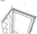
Figure 2 - is the detailed view of the cooling device when the door is open. -
Figure 3 - is the detailed view of the cooling device while the door changes from the closed position to the open position. -
Figure 4 - is the detailed view of the cooling device when the door is open. -
Figure 5 - is the exploded view of the housing and the illumination element. -
Figure 6 - is the view of another embodiment not forming part of the present invention. - The elements illustrated in the figures are numbered as follows:
- 1. Cooling device
- 2. Body
- 3. Door
- 4. Housing
- 5. Illumination element
- 6. Retainer
- 7. Extension
- 8. Biasing means
- The cooling device (1) comprises a body (2) wherein objects to be cooled are placed, a door (3) providing access from outside to inside of the body (2), a housing (4) disposed on the body (2) wall and an illumination element (5) that is pushed into the housing (4) by the bearing against of the door (3) part that enters into the body (2) while the door (3) is closed, and comes outside of the housing (4) towards the volume evacuated by the door (3) in the body (2) when the door (3) is opened (
Figure 1 ). - In the illumination element (5) a fluorescent tube lamp or LED can be used as the light source. The illumination element (5) is preferably configured as a tube that extends virtually along the side wall for illuminating the interior of the body (2) homogeneously. The illumination element (5) is in the active position upon leaving the housing (4) and illuminates the interior of the body (2).
- The housing (4) is disposed on the side, top and/or bottom wall of the body (2) in the vicinity of the door (3) portion extending into the body (2) when the door (3) is closed. Thus, the illumination element (5) disposed inside the housing (4) can be moved by the door (3) (
Figure 6 ). - The illumination element (5) going outside the housing (4) when the door (3) is open, and entering into the housing (4) when the door (3) is closed depending on the movement of the door (3), maintains the illumination element (5) not to occupy an additional space inside the body (2).
- The cooling device (1) comprises one or more retainers (6) whereon the illumination element (5) is mounted, providing the illumination element (5) to be at least partially carried outside the housing (4), said retainer (6) comprising one or more pins for mounting the retainer (6) into the housing (4) such that a rotational axis is formed, and one or more biasing means (8) that push the retainer (6) outwards from the housing (4), maintaining the retainer (6) and the illumination element (5) connected thereto to automatically leave the housing when the force applied on the retainer (6) is released. In the preferred embodiment of the present invention, two pins situated on the same axis are provided inside the housing (4). The pins, remaining on the same axis, are fitted to the retainer (6) and the illumination element (5) is attached on the retainer(s) (6) to remain between the two opposite surfaces of the housing (4) (
Figure 5 ). - In the present invention, the illumination element (5) remains inside the housing (4) disposed on the side wall of the body (2), corresponding to the portion of the door (3) extending into the body (2) when the door (3) is closed. Since the door (3) overcomes the force of the biasing means (8) when closed by applying pressure on the retainer (6), maintains the illumination element (5) to remain inside the housing (4). In this position, the illumination element (5) does not form any protrusion on the body (2). Moreover, since the housing (4) and the illumination element (5) are situated in the volume occupied by the door (3) inside the body (2) when the door (3) is closed, they do not occupy an additional volume inside the body (2) when the door (3) is closed.
- When the door (3) is opened by the user, the force applied on the retainer (6) by the door (3) is released by the movement of the door (3) and the biasing means (8) force shows its effect by pushing the retainer (6) with the illumination element (5) thereon out of the housing (4). During opening of the door (3), the illumination element (5) moving together with the retainer (6) goes out of the housing (4) by the force effect of the biasing means (8) and extends towards the volume evacuated by the door (3). When the door (3) is opened, the illumination element (5) has left the housing (4). The illumination element (5) is turned on by being in the active position upon leaving the housing (4) and illuminates the interior of the body (2). In this embodiment, the illumination element (5) illuminates the cooling volume from the front towards the rear of the body (2).
- In another embodiment of the present invention, the cooling device (1) comprises an extension (7), situated on the door (3) at the portion corresponding to the retainer (6), that pushes the retainer (6) when the door (3) is closed so that the illumination element (5) remains inside the housing (4). The force applied by the extension (7) on the retainer (6) is released while the door (3) is opened. In this position, the retainer (6) starts moving from the housing (4) towards the cooling volume in proportion with the force of the biasing means (8) applied thereon. The movement of the door (3) can be more easily and safely transferred to the retainer (6) by means of the extension (7) (
Figure 2 ,Figure 3 andFigure 4 ). - In another embodiment of the present invention, the housing (4) is situated on the wall at the side whereto the door (3) is mounted to the body (2) and is on the side close to the door (3). On the other hand, the extension (7) is at the side of the door (3) mounted to the body (2), at a point of exerting force on the retainer (6) in the housing (4) when the door (3) is open. In this embodiment, moreover the housing (4) extends parallel to the side of the body (2) from the top to the bottom of the body (2). Since the illumination element (5) placed inside the said housing (4) extends along all of the shelves disposed inside the body (2), thereby the shelves are illuminated almost homogeneously.
- In an embodiment of the present invention, the retainer (6) is prism shaped and the illumination element (5) is disposed in the retainer (6). In this position, the retainer (6) surrounds the illumination element (5) entirely or partially. Thus, the illumination element (5) is both protected and the housing (4) is covered when the door (3) is closed. The retainer (6) is placed in the housing (4) to be rotatable from the upper and lower base by means of pins. The rotational axis formed by the pins remains within the housing (4). During the rotational movement, at least two side surfaces go out of the housing (4) and one side surface remains at least partially in the housing (4).
- The retainer (6) comprises an aperture or at least one transparent side surface. This side surface is preferably the side surface facing the cooling volume.
- In another version of this embodiment of the present invention, the retainer (6) comprises at least one side surface having reflective features for directing the beams emanating from the illumination element (5) into the cooling volume.
- In another embodiment of the present invention, the retainer (6) and the illumination element (5) are fitted into the housing (4) by means of a push-in, pop-out mechanism and moves by the help of this mechanism. By means of this embodiment, the retainer (6) and the illumination element (5) connected thereto can also be inserted into the housing (4) by the user when the door (3) is open or moved outwards from the housing (4) independently from the movement of the door (3).
- By means of the present invention, the cooling volume is illuminated homogeneously by the illumination element (5) that does not occupy any additional space in the body (2) when the door is closed.
Claims (10)
- A cooling device (1) that comprises a body (2) wherein objects to be cooled are placed, and a door (3) providing access from outside to inside of the body (2), wherein a housing (4) is disposed on the body (2) wall, and wherein an illumination element (5) is pushed into the housing (4) by bearing against a door part that goes into the body (2) while the door (3) is closed, and comes out of the housing (4) towards the volume evacuated by the door (3) in the body (2) when the door (3) is opened, characterized in that the housing (4) extends parallel to the side of the body (2) from a top towards a bottom of the body (2) and the illumination element (5) is placed inside said housing (4), the illumination element (5) having a height and length that provides an equal amount of light to shelves situated in a cooling volume in a region near the door (3) on a side wall of the body (2) wherein the illumination element (5) illuminates the cooling volume from a front towards a rear of the body (2).
- A cooling device (1) as in Claim 1, characterized in that said housing (4) is disposed on the side wall of the body (2) at the vicinity wherein the portion of the door extends into the body (2) when the door (3) is closed.
- A cooling device (1) as in Claims 1 or 2, characterized by one or more retainers (6) whereon the illumination element (5) is mounted, providing the illumination element (5) to be at least partially carried outside the housing (4), said retainer (6) comprising one or more pins for mounting the retainer (6) into the housing (4) such that a rotational axis is formed, and one or more biasing means (8) that push the retainer (6) outwards from the housing (4) maintaining the retainer (6) and the illumination element (5) connected thereto to automatically leave the housing when a force applied on the retainer (6) is released.
- A cooling device (1) as in any one of the above claims, characterized in that the illumination element (5) illuminates the cooling volume from the front towards the rear of the body (2).
- A cooling device (1) as in any one of the above claims, characterized by an extension (7), situated on the door (3) at the portion corresponding to the retainer (6), said extension (7) pushes the retainer (6) when the door (3) is closed so that the illumination element (5) remains inside the housing (4).
- A cooling device (1) as in Claim 5, characterized in that said housing (4) is situated at a side whereto the door (3) is mounted on the body (2), on the side of the body (2) close to the door (3) and the extension (7) is disposed at the side of the door (3) at a point for exerting force on the retainer (6) in the housing (4) when the door (3) is open.
- A cooling device (1) as in any one of the above claims, characterized by a retainer (6) that comprises an aperture or at least one transparent side wall.
- A cooling device (1) as in Claim 7, characterized in that said retainer (6) comprises at least one side wall having reflective features for directing the beams emanating from the illumination element (5) to an inside of the cooling volume.
- A cooling device (1) as in any one of the above claims, characterized by a push-in, pop-out mechanism for mounting the illumination element (5) into the housing (4).
- A cooling device (1) as in any one of the above claims, characterized by an illumination element (5) that illuminates the interior of the body (2) by being in an active position upon leaving the housing (4).
Priority Applications (1)
| Application Number | Priority Date | Filing Date | Title |
|---|---|---|---|
| PL08760483T PL2150760T3 (en) | 2007-06-05 | 2008-06-04 | A cooling device |
Applications Claiming Priority (2)
| Application Number | Priority Date | Filing Date | Title |
|---|---|---|---|
| TR200703868 | 2007-06-05 | ||
| PCT/EP2008/056901 WO2008148789A2 (en) | 2007-06-05 | 2008-06-04 | A cooling device |
Publications (2)
| Publication Number | Publication Date |
|---|---|
| EP2150760A2 EP2150760A2 (en) | 2010-02-10 |
| EP2150760B1 true EP2150760B1 (en) | 2017-11-01 |
Family
ID=40094227
Family Applications (1)
| Application Number | Title | Priority Date | Filing Date |
|---|---|---|---|
| EP08760483.1A Active EP2150760B1 (en) | 2007-06-05 | 2008-06-04 | A cooling device |
Country Status (4)
| Country | Link |
|---|---|
| EP (1) | EP2150760B1 (en) |
| CN (1) | CN101680711A (en) |
| PL (1) | PL2150760T3 (en) |
| WO (1) | WO2008148789A2 (en) |
Families Citing this family (1)
| Publication number | Priority date | Publication date | Assignee | Title |
|---|---|---|---|---|
| BR102014013430A2 (en) * | 2014-06-03 | 2015-12-29 | Whirlpool Sa | integrated lighting system for household appliances, and home appliance provided with said lighting system |
Family Cites Families (4)
| Publication number | Priority date | Publication date | Assignee | Title |
|---|---|---|---|---|
| DE4024174C1 (en) * | 1990-07-30 | 1991-07-18 | Bosch-Siemens Hausgeraete Gmbh, 8000 Muenchen, De | |
| KR20000031579A (en) * | 1998-11-07 | 2000-06-05 | 전주범 | Door switch of refrigerator having indoor lamp |
| DE10107654A1 (en) * | 2001-02-19 | 2002-08-29 | Bsh Bosch Siemens Hausgeraete | Refrigerator, has the lighting unit mounted outside the inner refrigerator chamber and coupled to the door to be displaced between inactive position with door closed, and active position with door open |
| WO2008148833A1 (en) * | 2007-06-07 | 2008-12-11 | Arcelik Anonim Sirketi | A cooling device |
-
2008
- 2008-06-04 EP EP08760483.1A patent/EP2150760B1/en active Active
- 2008-06-04 CN CN200880018982A patent/CN101680711A/en active Pending
- 2008-06-04 WO PCT/EP2008/056901 patent/WO2008148789A2/en not_active Ceased
- 2008-06-04 PL PL08760483T patent/PL2150760T3/en unknown
Non-Patent Citations (1)
| Title |
|---|
| None * |
Also Published As
| Publication number | Publication date |
|---|---|
| EP2150760A2 (en) | 2010-02-10 |
| CN101680711A (en) | 2010-03-24 |
| PL2150760T3 (en) | 2018-04-30 |
| WO2008148789A2 (en) | 2008-12-11 |
| WO2008148789A3 (en) | 2009-04-30 |
Similar Documents
| Publication | Publication Date | Title |
|---|---|---|
| JP4264654B2 (en) | Vehicle console device | |
| WO2008148833A1 (en) | A cooling device | |
| KR102014148B1 (en) | Refrigerator | |
| US10317130B2 (en) | Refrigeration appliance having a light | |
| US7850326B2 (en) | Illumination device for items of furniture | |
| WO2020194682A1 (en) | Refrigerator | |
| JP2008089244A (en) | refrigerator | |
| US4600978A (en) | Illuminator | |
| EP2433071B1 (en) | A cooling device whereof the lid is illuminated | |
| EP2150760A2 (en) | A cooling device | |
| US8445801B2 (en) | Switch | |
| KR100814517B1 (en) | Damper integrated switch for glovebox lamp | |
| US20070187195A1 (en) | Glove box lamp switch | |
| WO2020058746A1 (en) | Illumination for refrigerator | |
| JP6388796B2 (en) | Vehicle console device | |
| CN219687188U (en) | Storage components and vehicles in the vehicle center console | |
| EP2217873B1 (en) | A cooling device | |
| JP7096229B2 (en) | Storage | |
| JPH0119029Y2 (en) | ||
| JP4308415B2 (en) | Room mirror and interior light | |
| JP2006023928A (en) | Component mounting structure for automatic vending machine | |
| KR200217542Y1 (en) | Refrigerator | |
| GB2247402A (en) | Internal lighting in a cooling appliance | |
| KR101768649B1 (en) | lamp assembly for auto operating and vehicle having it | |
| KR100427980B1 (en) | Folding Slide-Cup Holder-Mount Structure in Automobile-Console Box |
Legal Events
| Date | Code | Title | Description |
|---|---|---|---|
| PUAI | Public reference made under article 153(3) epc to a published international application that has entered the european phase |
Free format text: ORIGINAL CODE: 0009012 |
|
| 17P | Request for examination filed |
Effective date: 20091114 |
|
| AK | Designated contracting states |
Kind code of ref document: A2 Designated state(s): AT BE BG CH CY CZ DE DK EE ES FI FR GB GR HR HU IE IS IT LI LT LU LV MC MT NL NO PL PT RO SE SI SK TR |
|
| AX | Request for extension of the european patent |
Extension state: AL BA MK RS |
|
| DAX | Request for extension of the european patent (deleted) | ||
| 17Q | First examination report despatched |
Effective date: 20170118 |
|
| GRAP | Despatch of communication of intention to grant a patent |
Free format text: ORIGINAL CODE: EPIDOSNIGR1 |
|
| INTG | Intention to grant announced |
Effective date: 20170728 |
|
| GRAS | Grant fee paid |
Free format text: ORIGINAL CODE: EPIDOSNIGR3 |
|
| GRAA | (expected) grant |
Free format text: ORIGINAL CODE: 0009210 |
|
| AK | Designated contracting states |
Kind code of ref document: B1 Designated state(s): AT BE BG CH CY CZ DE DK EE ES FI FR GB GR HR HU IE IS IT LI LT LU LV MC MT NL NO PL PT RO SE SI SK TR |
|
| REG | Reference to a national code |
Ref country code: GB Ref legal event code: FG4D |
|
| REG | Reference to a national code |
Ref country code: CH Ref legal event code: EP Ref country code: AT Ref legal event code: REF Ref document number: 942453 Country of ref document: AT Kind code of ref document: T Effective date: 20171115 |
|
| REG | Reference to a national code |
Ref country code: IE Ref legal event code: FG4D |
|
| REG | Reference to a national code |
Ref country code: DE Ref legal event code: R096 Ref document number: 602008052767 Country of ref document: DE |
|
| REG | Reference to a national code |
Ref country code: NL Ref legal event code: MP Effective date: 20171101 |
|
| REG | Reference to a national code |
Ref country code: LT Ref legal event code: MG4D |
|
| REG | Reference to a national code |
Ref country code: AT Ref legal event code: MK05 Ref document number: 942453 Country of ref document: AT Kind code of ref document: T Effective date: 20171101 |
|
| PG25 | Lapsed in a contracting state [announced via postgrant information from national office to epo] |
Ref country code: SE Free format text: LAPSE BECAUSE OF FAILURE TO SUBMIT A TRANSLATION OF THE DESCRIPTION OR TO PAY THE FEE WITHIN THE PRESCRIBED TIME-LIMIT Effective date: 20171101 Ref country code: ES Free format text: LAPSE BECAUSE OF FAILURE TO SUBMIT A TRANSLATION OF THE DESCRIPTION OR TO PAY THE FEE WITHIN THE PRESCRIBED TIME-LIMIT Effective date: 20171101 Ref country code: NO Free format text: LAPSE BECAUSE OF FAILURE TO SUBMIT A TRANSLATION OF THE DESCRIPTION OR TO PAY THE FEE WITHIN THE PRESCRIBED TIME-LIMIT Effective date: 20180201 Ref country code: NL Free format text: LAPSE BECAUSE OF FAILURE TO SUBMIT A TRANSLATION OF THE DESCRIPTION OR TO PAY THE FEE WITHIN THE PRESCRIBED TIME-LIMIT Effective date: 20171101 Ref country code: LT Free format text: LAPSE BECAUSE OF FAILURE TO SUBMIT A TRANSLATION OF THE DESCRIPTION OR TO PAY THE FEE WITHIN THE PRESCRIBED TIME-LIMIT Effective date: 20171101 Ref country code: FI Free format text: LAPSE BECAUSE OF FAILURE TO SUBMIT A TRANSLATION OF THE DESCRIPTION OR TO PAY THE FEE WITHIN THE PRESCRIBED TIME-LIMIT Effective date: 20171101 |
|
| PG25 | Lapsed in a contracting state [announced via postgrant information from national office to epo] |
Ref country code: BG Free format text: LAPSE BECAUSE OF FAILURE TO SUBMIT A TRANSLATION OF THE DESCRIPTION OR TO PAY THE FEE WITHIN THE PRESCRIBED TIME-LIMIT Effective date: 20180201 Ref country code: IS Free format text: LAPSE BECAUSE OF FAILURE TO SUBMIT A TRANSLATION OF THE DESCRIPTION OR TO PAY THE FEE WITHIN THE PRESCRIBED TIME-LIMIT Effective date: 20180301 Ref country code: HR Free format text: LAPSE BECAUSE OF FAILURE TO SUBMIT A TRANSLATION OF THE DESCRIPTION OR TO PAY THE FEE WITHIN THE PRESCRIBED TIME-LIMIT Effective date: 20171101 Ref country code: AT Free format text: LAPSE BECAUSE OF FAILURE TO SUBMIT A TRANSLATION OF THE DESCRIPTION OR TO PAY THE FEE WITHIN THE PRESCRIBED TIME-LIMIT Effective date: 20171101 Ref country code: GR Free format text: LAPSE BECAUSE OF FAILURE TO SUBMIT A TRANSLATION OF THE DESCRIPTION OR TO PAY THE FEE WITHIN THE PRESCRIBED TIME-LIMIT Effective date: 20180202 Ref country code: LV Free format text: LAPSE BECAUSE OF FAILURE TO SUBMIT A TRANSLATION OF THE DESCRIPTION OR TO PAY THE FEE WITHIN THE PRESCRIBED TIME-LIMIT Effective date: 20171101 |
|
| REG | Reference to a national code |
Ref country code: FR Ref legal event code: PLFP Year of fee payment: 11 |
|
| PG25 | Lapsed in a contracting state [announced via postgrant information from national office to epo] |
Ref country code: CZ Free format text: LAPSE BECAUSE OF FAILURE TO SUBMIT A TRANSLATION OF THE DESCRIPTION OR TO PAY THE FEE WITHIN THE PRESCRIBED TIME-LIMIT Effective date: 20171101 Ref country code: SK Free format text: LAPSE BECAUSE OF FAILURE TO SUBMIT A TRANSLATION OF THE DESCRIPTION OR TO PAY THE FEE WITHIN THE PRESCRIBED TIME-LIMIT Effective date: 20171101 Ref country code: CY Free format text: LAPSE BECAUSE OF FAILURE TO SUBMIT A TRANSLATION OF THE DESCRIPTION OR TO PAY THE FEE WITHIN THE PRESCRIBED TIME-LIMIT Effective date: 20171101 Ref country code: DK Free format text: LAPSE BECAUSE OF FAILURE TO SUBMIT A TRANSLATION OF THE DESCRIPTION OR TO PAY THE FEE WITHIN THE PRESCRIBED TIME-LIMIT Effective date: 20171101 Ref country code: EE Free format text: LAPSE BECAUSE OF FAILURE TO SUBMIT A TRANSLATION OF THE DESCRIPTION OR TO PAY THE FEE WITHIN THE PRESCRIBED TIME-LIMIT Effective date: 20171101 |
|
| REG | Reference to a national code |
Ref country code: DE Ref legal event code: R097 Ref document number: 602008052767 Country of ref document: DE |
|
| PG25 | Lapsed in a contracting state [announced via postgrant information from national office to epo] |
Ref country code: RO Free format text: LAPSE BECAUSE OF FAILURE TO SUBMIT A TRANSLATION OF THE DESCRIPTION OR TO PAY THE FEE WITHIN THE PRESCRIBED TIME-LIMIT Effective date: 20171101 |
|
| PGFP | Annual fee paid to national office [announced via postgrant information from national office to epo] |
Ref country code: PL Payment date: 20180529 Year of fee payment: 11 Ref country code: FR Payment date: 20180620 Year of fee payment: 11 |
|
| PLBE | No opposition filed within time limit |
Free format text: ORIGINAL CODE: 0009261 |
|
| STAA | Information on the status of an ep patent application or granted ep patent |
Free format text: STATUS: NO OPPOSITION FILED WITHIN TIME LIMIT |
|
| 26N | No opposition filed |
Effective date: 20180802 |
|
| PGFP | Annual fee paid to national office [announced via postgrant information from national office to epo] |
Ref country code: IT Payment date: 20180627 Year of fee payment: 11 Ref country code: GB Payment date: 20180620 Year of fee payment: 11 |
|
| PG25 | Lapsed in a contracting state [announced via postgrant information from national office to epo] |
Ref country code: SI Free format text: LAPSE BECAUSE OF FAILURE TO SUBMIT A TRANSLATION OF THE DESCRIPTION OR TO PAY THE FEE WITHIN THE PRESCRIBED TIME-LIMIT Effective date: 20171101 |
|
| REG | Reference to a national code |
Ref country code: CH Ref legal event code: PL |
|
| REG | Reference to a national code |
Ref country code: BE Ref legal event code: MM Effective date: 20180630 |
|
| REG | Reference to a national code |
Ref country code: IE Ref legal event code: MM4A |
|
| PG25 | Lapsed in a contracting state [announced via postgrant information from national office to epo] |
Ref country code: LU Free format text: LAPSE BECAUSE OF NON-PAYMENT OF DUE FEES Effective date: 20180604 Ref country code: MC Free format text: LAPSE BECAUSE OF FAILURE TO SUBMIT A TRANSLATION OF THE DESCRIPTION OR TO PAY THE FEE WITHIN THE PRESCRIBED TIME-LIMIT Effective date: 20171101 |
|
| PG25 | Lapsed in a contracting state [announced via postgrant information from national office to epo] |
Ref country code: LI Free format text: LAPSE BECAUSE OF NON-PAYMENT OF DUE FEES Effective date: 20180630 Ref country code: CH Free format text: LAPSE BECAUSE OF NON-PAYMENT OF DUE FEES Effective date: 20180630 Ref country code: IE Free format text: LAPSE BECAUSE OF NON-PAYMENT OF DUE FEES Effective date: 20180604 |
|
| PG25 | Lapsed in a contracting state [announced via postgrant information from national office to epo] |
Ref country code: BE Free format text: LAPSE BECAUSE OF NON-PAYMENT OF DUE FEES Effective date: 20180630 |
|
| PG25 | Lapsed in a contracting state [announced via postgrant information from national office to epo] |
Ref country code: MT Free format text: LAPSE BECAUSE OF NON-PAYMENT OF DUE FEES Effective date: 20180604 |
|
| GBPC | Gb: european patent ceased through non-payment of renewal fee |
Effective date: 20190604 |
|
| PG25 | Lapsed in a contracting state [announced via postgrant information from national office to epo] |
Ref country code: IT Free format text: LAPSE BECAUSE OF NON-PAYMENT OF DUE FEES Effective date: 20190604 Ref country code: GB Free format text: LAPSE BECAUSE OF NON-PAYMENT OF DUE FEES Effective date: 20190604 |
|
| PG25 | Lapsed in a contracting state [announced via postgrant information from national office to epo] |
Ref country code: HU Free format text: LAPSE BECAUSE OF FAILURE TO SUBMIT A TRANSLATION OF THE DESCRIPTION OR TO PAY THE FEE WITHIN THE PRESCRIBED TIME-LIMIT; INVALID AB INITIO Effective date: 20080604 Ref country code: PT Free format text: LAPSE BECAUSE OF FAILURE TO SUBMIT A TRANSLATION OF THE DESCRIPTION OR TO PAY THE FEE WITHIN THE PRESCRIBED TIME-LIMIT Effective date: 20171101 |
|
| PG25 | Lapsed in a contracting state [announced via postgrant information from national office to epo] |
Ref country code: FR Free format text: LAPSE BECAUSE OF NON-PAYMENT OF DUE FEES Effective date: 20190630 |
|
| PG25 | Lapsed in a contracting state [announced via postgrant information from national office to epo] |
Ref country code: PL Free format text: LAPSE BECAUSE OF NON-PAYMENT OF DUE FEES Effective date: 20190604 |
|
| PGFP | Annual fee paid to national office [announced via postgrant information from national office to epo] |
Ref country code: DE Payment date: 20250618 Year of fee payment: 18 |
|
| PGFP | Annual fee paid to national office [announced via postgrant information from national office to epo] |
Ref country code: TR Payment date: 20250520 Year of fee payment: 18 |