EP2150477B1 - Cuve de stockage - Google Patents
Cuve de stockage Download PDFInfo
- Publication number
- EP2150477B1 EP2150477B1 EP08759883A EP08759883A EP2150477B1 EP 2150477 B1 EP2150477 B1 EP 2150477B1 EP 08759883 A EP08759883 A EP 08759883A EP 08759883 A EP08759883 A EP 08759883A EP 2150477 B1 EP2150477 B1 EP 2150477B1
- Authority
- EP
- European Patent Office
- Prior art keywords
- vessel
- section
- tank
- sealing means
- collars
- Prior art date
- Legal status (The legal status is an assumption and is not a legal conclusion. Google has not performed a legal analysis and makes no representation as to the accuracy of the status listed.)
- Not-in-force
Links
- 238000003860 storage Methods 0.000 title claims abstract description 7
- 238000007789 sealing Methods 0.000 claims abstract description 25
- 238000005304 joining Methods 0.000 claims abstract description 11
- 239000011324 bead Substances 0.000 claims description 13
- 239000002184 metal Substances 0.000 claims description 8
- 239000000463 material Substances 0.000 claims description 6
- 238000001125 extrusion Methods 0.000 claims description 5
- 238000007373 indentation Methods 0.000 claims description 3
- 238000007689 inspection Methods 0.000 claims 1
- 238000004519 manufacturing process Methods 0.000 description 12
- 238000010276 construction Methods 0.000 description 5
- 230000002093 peripheral effect Effects 0.000 description 5
- 239000000523 sample Substances 0.000 description 4
- 238000009434 installation Methods 0.000 description 3
- 238000001175 rotational moulding Methods 0.000 description 3
- 230000004888 barrier function Effects 0.000 description 2
- -1 polyethylene Polymers 0.000 description 2
- 238000003466 welding Methods 0.000 description 2
- 239000004698 Polyethylene Substances 0.000 description 1
- 239000004743 Polypropylene Substances 0.000 description 1
- 239000000470 constituent Substances 0.000 description 1
- 230000007547 defect Effects 0.000 description 1
- 230000008021 deposition Effects 0.000 description 1
- 229920001971 elastomer Polymers 0.000 description 1
- 239000000806 elastomer Substances 0.000 description 1
- 239000013536 elastomeric material Substances 0.000 description 1
- 238000010891 electric arc Methods 0.000 description 1
- 239000012530 fluid Substances 0.000 description 1
- 235000013305 food Nutrition 0.000 description 1
- 239000003292 glue Substances 0.000 description 1
- 229930195733 hydrocarbon Natural products 0.000 description 1
- 150000002430 hydrocarbons Chemical class 0.000 description 1
- 238000005259 measurement Methods 0.000 description 1
- 238000000034 method Methods 0.000 description 1
- 239000004033 plastic Substances 0.000 description 1
- 229920003023 plastic Polymers 0.000 description 1
- 238000007747 plating Methods 0.000 description 1
- 229920000573 polyethylene Polymers 0.000 description 1
- 229920001155 polypropylene Polymers 0.000 description 1
- 238000000926 separation method Methods 0.000 description 1
- 239000010865 sewage Substances 0.000 description 1
- 125000006850 spacer group Chemical group 0.000 description 1
- 239000000126 substance Substances 0.000 description 1
- 238000002604 ultrasonography Methods 0.000 description 1
Images




Classifications
-
- B—PERFORMING OPERATIONS; TRANSPORTING
- B65—CONVEYING; PACKING; STORING; HANDLING THIN OR FILAMENTARY MATERIAL
- B65D—CONTAINERS FOR STORAGE OR TRANSPORT OF ARTICLES OR MATERIALS, e.g. BAGS, BARRELS, BOTTLES, BOXES, CANS, CARTONS, CRATES, DRUMS, JARS, TANKS, HOPPERS, FORWARDING CONTAINERS; ACCESSORIES, CLOSURES, OR FITTINGS THEREFOR; PACKAGING ELEMENTS; PACKAGES
- B65D90/00—Component parts, details or accessories for large containers
- B65D90/02—Wall construction
- B65D90/08—Interconnections of wall parts; Sealing means therefor
-
- B—PERFORMING OPERATIONS; TRANSPORTING
- B65—CONVEYING; PACKING; STORING; HANDLING THIN OR FILAMENTARY MATERIAL
- B65D—CONTAINERS FOR STORAGE OR TRANSPORT OF ARTICLES OR MATERIALS, e.g. BAGS, BARRELS, BOTTLES, BOXES, CANS, CARTONS, CRATES, DRUMS, JARS, TANKS, HOPPERS, FORWARDING CONTAINERS; ACCESSORIES, CLOSURES, OR FITTINGS THEREFOR; PACKAGING ELEMENTS; PACKAGES
- B65D90/00—Component parts, details or accessories for large containers
- B65D90/02—Wall construction
- B65D90/023—Modular panels
- B65D90/024—Modular panels with features of cylindrical curvature
-
- B—PERFORMING OPERATIONS; TRANSPORTING
- B65—CONVEYING; PACKING; STORING; HANDLING THIN OR FILAMENTARY MATERIAL
- B65D—CONTAINERS FOR STORAGE OR TRANSPORT OF ARTICLES OR MATERIALS, e.g. BAGS, BARRELS, BOTTLES, BOXES, CANS, CARTONS, CRATES, DRUMS, JARS, TANKS, HOPPERS, FORWARDING CONTAINERS; ACCESSORIES, CLOSURES, OR FITTINGS THEREFOR; PACKAGING ELEMENTS; PACKAGES
- B65D90/00—Component parts, details or accessories for large containers
- B65D90/02—Wall construction
- B65D90/06—Coverings, e.g. for insulating purposes
-
- F—MECHANICAL ENGINEERING; LIGHTING; HEATING; WEAPONS; BLASTING
- F16—ENGINEERING ELEMENTS AND UNITS; GENERAL MEASURES FOR PRODUCING AND MAINTAINING EFFECTIVE FUNCTIONING OF MACHINES OR INSTALLATIONS; THERMAL INSULATION IN GENERAL
- F16L—PIPES; JOINTS OR FITTINGS FOR PIPES; SUPPORTS FOR PIPES, CABLES OR PROTECTIVE TUBING; MEANS FOR THERMAL INSULATION IN GENERAL
- F16L23/00—Flanged joints
- F16L23/16—Flanged joints characterised by the sealing means
Definitions
- the present invention relates to a storage tank of large volume, that is to say whose unit of measurement is expressed in m 3 .
- This tank is of the type comprising a closure section closed by a bottom, another closure section or a bottom. It can still incorporate one or more intermediate section (s). At least two of these neighboring components are connected to one another via a junction means.
- a large volume storage tank is presented in particular in the patent application FR-A-2,715,385 .
- This tank comprises two end modules and several central modules assembled together.
- Each module generally has a cylindrical section being provided at its free end or at its two free ends, depending on whether it is an end module or a central module, a collar adapted to cooperate with a flange of another module for assembling, in a sealed manner, these two modules together.
- a metal annular profile having a T-section is interposed between two adjacent collars. The radial flange of this section, as well as the flanges, are traversed by holes in which are mounted fixing bolts.
- the applicant has sought to simplify the construction of such a tank by making it less expensive to manufacture and seeking to obtain an improved sealing performance of the tank over time.
- a storage tank of large volume comprising a closure section closed by a bottom, another closure section or a bottom and / or at least one intermediate section, at least two of these neighboring components being brought together.
- a connecting means comprising two collars made on the annular free ends of these two components being turned facing each other, a plurality of bolts passing through the two collars for the to assemble.
- the connecting means comprises a plurality of washers mounted on the screws of the bolts being interposed between the two flanges to form between them an annular volume for receiving a sealing means.
- the sealing means consists of a bead of a material identical to that of the two components and which is deposited by extrusion from the inside of the tank into the annular volume.
- this cord from the inside of the tank insinuates deep into the annular volume and covers the internal edges of the two collars, thus providing a perfectly sealed barrier between the inside and the outside of the tank.
- the tank incorporates an element intended, in cooperation with a control device, to qualify the quality of the sealing means.
- the defects of the sealing means which can not be detected by the eye, can thus be highlighted.
- the element consists of a metal rod placed in the annular volume, outside the sealing means.
- the echo emitted by the metal ring can be checked to assess the quality of the weld seam.
- a seal is housed in the annular volume, outside the sealing means.
- the seal is held prisoner between two indentations formed vis-a-vis respectively in the end faces of the two collars.
- This seal is advantageously manufactured by extrusion in an elastomeric material and then cut to length.
- the metal rod is interposed between the seal and the sealing means.
- the metal rod can be placed against the gasket in order to precisely position it for optimum operation of the weld bead tester.
- At least one end section comprises a curved type bottom.
- the end section and / or the intermediate section has externally mounting brackets for props.
- an end section comprises a flat type bottom.
- the tank 100 which is presented at Fig. 1 , is a storage tank of large volume whose capacity can reach several tens of m 3 .
- It is intended for multiple applications such as containing chemicals, hydrocarbons, food products. It is also suitable for collecting sewage, or for storing rainwater. It can still be used as separation or settling tank.
- the tank 100 essentially comprises, at this point Fig. 1 , an end section 200 closed by a convex bottom 210, at least one intermediate section 300 attached to the end section, and a bottom 400 of closure of the intermediate section and which is at this end.
- Fig. 1 a domed bottom.
- This tank is of horizontal type, that is to say that this tank is intended to rest horizontally on the ground or to be buried in this position.
- the different sections and the bottom are advantageously manufactured by a rotational molding process, a process that allows a fluid plastic material to conform to the inner walls of a heated mold or set of molds and is rotated.
- the material used for the manufacture of these constituents is preferably polyethylene or polypropylene.
- the end portion 200 comprises a peripheral wall 220, for example cylindrical, open on one side and closed on the other by a curved wall, forming one, 210, the bottom of the tank.
- the peripheral wall 220 has in longitudinal section a succession of corrugations 222 to provide the tank with sufficient mechanical strength when it is filled.
- the end section 200 is made in one piece.
- the bottom 210 of the peripheral wall 220 is provided, for the same purpose, ribs 212 to stiffen its structure.
- an opening 230 of the man-hole type passes through the peripheral wall of the end section 200.
- Orifices 240, 242 for connecting the tank 100 pass through the bottom 210.
- the intermediate section 300 also comprises a peripheral wall 320 provided with corrugations 322 like the end section 200.
- At least one of the sections and here the intermediate section 300 comprise on the outside supports 330 on which can be fixed load-bearing props exerted by the ground on tank.
- the tank 100 With a capacity greater than that of the Fig. 1 , comprises a first end section 200, an intermediate section 300 and a second end section 200 turned in the opposite direction of the first.
- a joining means 500 joins the two sections 200 and 300. Another joining means 500 also joins the intermediate section 300 and the base 400 ( Fig. 1 ) or the intermediate section 300 with the other end section 200 ( Fig. 2 ).
- the junction means 500 comprises two radial flanges 510, respectively formed on the free annular ends of the sections 200 and 300, projecting towards the outside of the tank, an assembly means 520 for joining the two flanges positioned in the form of screws. in order to assemble the two sections mutually, a sealing means 530 taking place in an annular volume 532 existing between the two flanges, and an element 540 intended, in cooperation with a control device, to be qualified the quality of the sealing means 530.
- the assembly means 520 consists of a plurality of bolts distributed at the periphery of the flanges and which are housed in holes 512 through the two flanges.
- a washer 522 is placed on the screw of each bolt, being interposed between the two flanges 510.
- the sealing means 530 is advantageously constituted by a bead of a material identical to that of the sections 200, 300 and bottom 400 and which is deposited by extrusion, for example using an extruder, into the annular volume. 532 and the inner side of the tank. During its deposition, the bead creeps deep into the annular volume 532 and covers the inner edges of the two flanges, thereby providing a perfectly sealed barrier between the inside and the outside of the tank.
- a rod 540 consisting of a metal wire, is placed in the annular volume 532, before removal. of cord 530. It is thus possible to control, by means of an apparatus, for example a device generating ultrasound and which is connected to a probe, the echo emitted by the ring 540 by moving the probe on the weld bead 530 to appreciate its quality.
- a seal 560 which should be place in the annular volume 532, and this before the installation of the ring 540 and the filing of the cord 530.
- This seal 560 of constant section, is manufactured in an elastomer. It is cut to length and then placed between two indentations 514 formed respectively on the end faces of the two collars 510. The seal is in this FIG. of circular section and each imprint 514 is formed of a semicircular groove. This seal 560 could, in particular, intervene in case of failure of the weld bead 530.
- a tooling 600 presented to the Fig. 5 and which can be adapted on a mold for manufacturing a section or several sections or a bottom.
- This tool must be mounted at the end of the mold. It thus comprises a ring 610 intended to form the end face of the flange 510 and which is fixed, for example, by welding on the manufacturing mold.
- This ring 610 consists of an outer ring 612, an inner ring 614, joined by a torus 620, interposed between them and which is intended to form the imprint 514 for the seal.
- junction means 500 between the intermediate section 300 and the bottom 400 is of the same type as that existing between the two sections 200 and 300.
- one or more other intermediate sections can be incorporated in the construction of the tank to increase its capacity.
- two intermediate sections 300 of the same capacity, a first end section 200 and a second end section 200 compose the tank 100.
- a joining means 500 such as that just described, then combines each end section 200 with an adjacent intermediate section 300, the two intermediate sections 300.
- the length 1 'of the second intermediate section 300' is less than that, 1, of the first intermediate section 300, thus providing them with two different capacities to propose, by combination, tanks in a wide range of capacity.
- the tank presented to Figs. 1 , 2 , 6 , 7 and 8 is a horizontal type tank.
- a tank 100 'of vertical type and presented to the Fig. 9 that is to say a tank that is intended to stand vertically on the ground, for example when the minimum footprint is sought.
- the tank here comprises two end sections 200 ', 200 "connected by a joining means 500.
- the opening 230', of the manhole type, here passes through the bottom wall 210 'of a section of 200 'end, that is to say an upper part of the tank 100'
- the other end section 200 "here incorporates a bottom 210", flat, to provide a stable base of the tank 100 'on the ground.
- a tank 100 or 100 'of the invention The construction of a tank 100 or 100 'of the invention is as follows. Assembled rotomolding components are pre-assembled on a flat and horizontal mounting bench, not shown. The tanks 100 horizontal type, 100 'or vertical type are built horizontally on this bench.
- end sections 200, 200 'or 200 ", the intermediate section or sections 300, 300' and, where appropriate, the bottom 400 are replaced in place of an end section 200, 200 'or 200". , in an alignment position, provisionally stalling them as needed.
- Each seal 560 is placed in a cavity 514. In order to hold it in place, it is possible to pre-glue the reception impression.
- the sections are then pre-assembled between them and, if necessary, the bottom with its neighboring section, with bolts 520 that are threaded into the holes 512 and placing the spacer washers around the screws between two flanges. 510 neighbors.
- the next step is to deposit a cord 530 of material extruded into the annular volume 532 existing between two neighboring collars 510 for sealing sealing sections between them and the bottom with its neighbor section, if this is the case.
- the welds are then checked by moving on the surface of each bead 530 the probe of a control device operating by emission of ultrasonic waves to check the quality of the welds and thus the tightness of the tank.
- the manufacture of the tank can be completed by the installation of accessories, such as the installation of connections, a cover closing the manhole.
- the vessel of the invention is of a simpler construction to implement and less expensive to manufacture than that known from the state of the art.
- tanks can be built covering a wide range of capacities from standard rotomoulded elements.
Landscapes
- Engineering & Computer Science (AREA)
- Mechanical Engineering (AREA)
- General Engineering & Computer Science (AREA)
- Pressure Vessels And Lids Thereof (AREA)
- Developing Agents For Electrophotography (AREA)
- Electrical Discharge Machining, Electrochemical Machining, And Combined Machining (AREA)
- Supply Devices, Intensifiers, Converters, And Telemotors (AREA)
- Filling Or Discharging Of Gas Storage Vessels (AREA)
- Package Specialized In Special Use (AREA)
Description
- La présente invention concerne une cuve de stockage de grand volume, c'est-à-dire dont l'unité de mesure s'exprime en m3. Cette cuve est du type comportant un tronçon de fermeture fermé par un fond, un autre tronçon de fermeture ou un fond. Elle peut encore incorporer un ou plusieurs tronçon(s) intercalaire(s). Au moins deux de ces composants voisins sont réunis l'un à l'autre par l'intermédiaire d'un moyen de jonction.
- Une cuve de stockage de grand volume est présentée en particulier dans la demande de brevet
FR-A-2 715 385 - Le demandeur a cherché à simplifier la construction d'une telle cuve en la rendant moins onéreuse à fabriquer et en cherchant à obtenir une tenue à l'étanchéité améliorée de la cuve dans le temps.
- A cet effet, est proposée une cuve de stockage de grand volume, comprenant un tronçon de fermeture fermé par un fond, un autre tronçon de fermeture ou un fond et/ou au moins un tronçon intercalaire, au moins deux de ces composants voisins étant réunis l'un à l'autre par l'intermédiaire d'un moyen de jonction comprenant deux collerettes réalisées sur les extrémités libres annulaires de ces deux composants en étant tournées en vis-à-vis, une pluralité de boulons traversant les deux collerettes pour les assembler. Selon l'invention, le moyen de jonction comprend une pluralité de rondelles montées sur les vis des boulons en étant interposées entre les deux collerettes pour former entre elles un volume annulaire de réception d'un moyen d'étanchéité.
- Par cette construction, on assemble de manière économique et néanmoins très efficace les différents composants de la cuve et l'on prévoit une réservation de largeur calibrée pour réceptionner un moyen d'étanchéité.
- Selon une caractéristique additionnelle de l'invention, le moyen d'étanchéité est constitué d'un cordon d'une matière identique à celle des deux composants et qui est déposé par extrusion depuis l'intérieur de la cuve dans le volume annulaire.
- L'application de ce cordon depuis l'intérieur de la cuve s'insinue profondément dans le volume annulaire et recouvre les rebords internes des deux collerettes, procurant ainsi une barrière parfaitement étanche entre l'intérieur et l'extérieur de la cuve.
- Selon une caractéristique additionnelle de l'invention, la cuve incorpore un élément destiné, en coopération avec un appareil de contrôle, à qualifier la qualité du moyen d'étanchéité.
- Les défauts du moyen d'étanchéité, non détectables à l'oeil, peuvent ainsi être mis en évidence.
- Selon une caractéristique additionnelle de l'invention, l'élément est constitué d'un jonc métallique placé dans le volume annulaire, à l'extérieur du moyen d'étanchéité.
- En déplaçant un palpeur d'un appareil de contrôle sur le moyen d'étanchéité, on peut contrôler l'écho émis par le jonc métallique pour apprécier la qualité du cordon de soudure.
- Selon une caractéristique additionnelle de l'invention, un joint est logé dans le volume annulaire, à l'extérieur du moyen d'étanchéité.
- En plaçant un joint d'étanchéité supplémentaire entre les deux collerettes, on peut pallier à une éventuelle défaillance du joint principal.
- Selon une caractéristique additionnelle de l'invention, le joint est maintenu prisonnier entre deux empreintes formées en vis-à-vis respectivement dans les faces d'extrémité des deux collerettes.
- Ce joint est avantageusement fabriqué par extrusion dans une matière élastomère puis coupé à longueur.
- Selon une caractéristique additionnelle de l'invention, le jonc métallique est interposé entre le joint et le moyen d'étanchéité.
- On peut de la sorte placer le jonc métallique contre le joint afin de le positionner avec précision pour obtenir un fonctionnement optimum de l'appareil de contrôle du cordon de soudure.
- Selon une caractéristique additionnelle de l'invention, au moins un tronçon d'extrémité comprend un fond de type bombé.
- Selon une caractéristique additionnelle de l'invention, le tronçon d'extrémité et/ou le tronçon intercalaire comporte extérieurement des supports de fixation pour des étais.
- Selon une caractéristique additionnelle de l'invention, un tronçon d'extrémité comprend un fond de type plat.
- Les caractéristiques de l'invention mentionnées ci-dessus, ainsi que d'autres, apparaîtront plus clairement à la lecture de la description suivante d'un exemple de réalisation, ladite description étant faite en relation avec les dessins joints, parmi lesquels:
- la
Fig. 1 représente une vue latérale d'une cuve incluant un tronçon d'extrémité, un tronçon intercalaire, ainsi qu'un fond de fermeture du tronçon intercalaire selon l'invention, - la
Fig. 2 représente une vue latérale d'une cuve incluant un tronçon d'extrémité, un tronçon intercalaire, ainsi qu'un autre un tronçon d'extrémité selon l'invention, - la
Fig. 3 représente une vue d'extrémité d'une cuve selon l'invention, - la
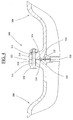
Fig. 4 représente une vue en détail d'un assemblage de deux tronçons d'une cuve selon l'invention, - la
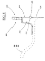
Fig. 5 représente un outillage destiné à former dans un moule de fabrication, une collerette sur un tronçon ou sur un fond pour une cuve selon l'invention, - la
Fig. 6 représente une vue latérale d'une cuve incluant un tronçon d'extrémité, deux tronçons intercalaires ainsi qu'un autre tronçon d'extrémité selon l'invention, - la
Fig. 7 représente une vue latérale d'une cuve incluant un tronçon d'extrémité, deux tronçons intercalaires de volumes différents ainsi qu'un autre tronçon d'extrémité selon l'invention, - la
Fig. 8 représente une vue latérale d'une cuve incluant deux modules, chaque module, fabriqué d'un seul tenant, incluant un tronçon d'extrémité et un tronçon intercalaire selon l'invention et, - la
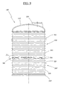
Fig. 9 représente une vue latérale d'une variante de réalisation d'une cuve selon l'invention. - La cuve 100, qui est présentée à la
Fig. 1 , est une cuve de stockage de grand volume dont la capacité peut atteindre plusieurs dizaines de m3. - Elle est destinée à de multiples applications comme contenir des produits chimiques, des hydrocarbures, des produits alimentaires. Elle convient également pour collecter des eaux d'assainissement, ou pour stocker des eaux pluviales. Elle peut encore être utilisée comme cuve de séparation ou de décantation.
- La cuve 100 comprend essentiellement, à cette
Fig. 1 , un tronçon d'extrémité 200 fermé par un fond 210 bombé, au moins un tronçon intercalaire 300 accolé au tronçon d'extrémité, ainsi qu'un fond 400 de fermeture du tronçon intercalaire et qui est à cetteFig. 1 un fond bombé. Cette cuve est de type horizontal, c'est-à-dire que cette cuve est destinée à reposer horizontalement sur le sol ou à être enterrée dans cette position. - Les différents tronçons et le fond sont avantageusement fabriqués par un procédé de rotomoulage, procédé permettant à une matière plastique fluide d'épouser les parois intérieures d'un moule ou d'un ensemble de moules chauffé et qui est mis en rotation. La matière utilisée pour la fabrication de ces constituants est préférentiellement du polyéthylène ou du polypropylène.
- Le tronçon d'extrémité 200 comprend une paroi périphérique 220, par exemple cylindrique, ouverte d'un côté et fermée de l'autre par une paroi bombée, formant l'un, 210, des fonds de la cuve. La paroi périphérique 220 présente en coupe longitudinale une succession d'ondulations 222 pour procurer à la cuve une tenue mécanique suffisante lorsqu'elle est remplie. Le tronçon d'extrémité 200 est fabriqué d'un seul tenant.
- A la
Fig. 3 , le fond 210 de la paroi périphérique 220 est pourvu, dans le même but, de nervures 212 pour rigidifier sa structure. - Aux
Figs. 1 et3 , une ouverture 230, de type trou d'homme, traverse la paroi périphérique du tronçon d'extrémité 200. Des orifices 240, 242 de raccordement de la cuve 100 traversent le fond 210. - A la
Fig. 1 , le tronçon intercalaire 300 comprend lui aussi une paroi périphérique 320 pourvue d'ondulations 322 à l'instar du tronçon d'extrémité 200. - Il peut également être pourvu d'une ouverture de type trou d'homme, et comporter des crochets, non représentés, pour permettre sa manutention et celle de la cuve 100.
- Pour reprendre les efforts verticaux que subit la cuve lorsqu'elle est enterrée, au moins l'un des tronçons et ici le tronçon intercalaire 300 comportent extérieurement des supports 330 sur lesquels peuvent être fixés des étais de reprise de charges qu'exerce le sol sur la cuve.
- A la
Fig. 2 , la cuve 100, d'une capacité supérieure à celle de laFig. 1 , comprend un premier tronçon d'extrémité 200, un tronçon intercalaire 300 ainsi qu'un second tronçon d'extrémité 200 tourné en sens inverse du premier. - Un moyen de jonction 500 réunit les deux tronçons 200 et 300. Un autre moyen de jonction 500 réunit également le tronçon intercalaire 300 et le fond 400 (
Fig. 1 ) ou le tronçon intercalaire 300 avec l'autre tronçon d'extrémité 200 (Fig. 2 ). - A la
Fig. 4 , le moyen de jonction 500 comprend deux collerettes 510 radiales, réalisées respectivement sur les extrémités annulaires libres des tronçons 200 et 300, en faisant saille vers l'extérieur de la cuve, un moyen d'assemblage 520 pour réunir les deux collerettes positionnées en vis-à-vis afin d'assembler mutuellement les deux tronçons, un moyen d'étanchéité 530 prenant place dans un volume annulaire 532 existant entre les deux collerettes, ainsi qu'un élément 540 destiné, en coopération avec un appareil de contrôle, à qualifier la qualité du moyen d'étanchéité 530. - On remarquera à la
Fig. 1 que le tronçon d'extrémité 200 ainsi que le fond 400 sont pourvus respectivement d'une seule collerette 510 sur leur unique extrémité annulaire alors que le tronçon intercalaire 300 en comporte deux, c'est-à-dire une sur chaque extrémité annulaire. - A la
Fig. 4 , le moyen d'assemblage 520 est constitué d'une pluralité de boulons répartis à la périphérie des collerettes et qui sont logés dans des trous 512 traversant les deux collerettes. Pour ménager le volume annulaire 532 entre les deux collerettes, en particulier pour placer le moyen d'étanchéité 530, une rondelle 522 est placée sur la vis de chaque boulon, en étant interposée entre les deux collerettes 510. - Le moyen d'étanchéité 530 est avantageusement constitué par un cordon d'une matière identique à celle des tronçons 200, 300 et du fond 400 et qui est déposé par extrusion, par exemple à l'aide d'une extrudeuse, dans le volume annulaire 532 et du côté intérieur de la cuve. Pendant son dépôt, le cordon s'insinue profondément dans le volume annulaire 532 et recouvre les rebords internes des deux collerettes, procurant ainsi une barrière parfaitement étanche entre l'intérieur et l'extérieur de la cuve.
- Pour s'assurer que le cordon de soudure est parfaitement continu ou n'incorpore pas de bulles d'air susceptibles de compromettre son étanchéité, un jonc 540, constitué d'un fil métallique, est placé dans le volume annulaire 532, avant la dépose du cordon 530. On peut ainsi contrôler, à l'aide d'un appareil, par exemple un appareil générant des ultrasons et qui est raccordé à un palpeur, l'écho émis par le jonc 540 en déplaçant le palpeur sur le cordon de soudure 530 pour apprécier sa qualité.
- La présence, en particulier, de bulles à l'intérieur du cordon, non détectables à l'oeil nu, est mise en évidence par ce contrôle.
- Pour procurer un niveau d'étanchéité irréprochable de la cuve, on peut prévoir, en supplément du cordon de soudure 530, un joint 560 qu'il convient de placer dans le volume annulaire 532, et ceci avant la pose du jonc 540 et le dépôt du cordon 530.
- Ce joint 560, de section constante, est fabriqué dans un élastomère. Il est coupé à longueur, puis placé entre deux empreintes 514 formées respectivement sur les faces d'extrémité des deux collerettes 510. Le joint est sur cette Fig. de section circulaire et chaque empreinte 514 est formée d'une gorge semi-circulaire. Ce joint 560 pourrait, en particulier, intervenir en cas de défaillance du cordon de soudure 530.
- La fabrication de cette empreinte, et plus généralement de la collerette, est mise en oeuvre par un outillage 600 présenté à la
Fig. 5 et qui peut être adapté sur un moule de fabrication d'un tronçon ou de plusieurs tronçons ou encore d'un fond. Cet outillage doit être monté en bout du moule. Il comprend ainsi une couronne 610 destinée à former la face d'extrémité de la collerette 510 et qui est fixée, par exemple, par soudage sur le moule de fabrication. Cette couronne 610 est constituée d'une couronne externe 612, d'une couronne interne 614, réunies par un tore 620, interposé entre elles et qui est destiné à former l'empreinte 514 pour le joint. - Lorsque ce joint 560 est présent, comme cela apparaît à la
Fig. 4 , il est avantageux de placer le jonc 540 contre le joint 560 pour le positionner à une distance constante des rebords internes des deux collerettes 510, afin d'obtenir un fonctionnement optimum de l'appareil de contrôle du cordon de soudure 530. - On remarquera, à la
Fig. 1 , que le moyen de jonction 500 entre le tronçon intercalaire 300 et le fond 400 est du même type que celui existant entre les deux tronçons 200 et 300. - Par ailleurs, un ou plusieurs autres tronçons intercalaires peuvent être incorporés dans la construction de la cuve pour accroître sa capacité. A la
Fig. 6 , deux tronçons intercalaires 300 de même capacité, un premier tronçon d'extrémité 200, ainsi qu'un second tronçon d'extrémité 200 composent la cuve 100. Un moyen de jonction 500, tel que celui qui vient d'être décrit, réunit alors chaque tronçon d'extrémité 200 avec un tronçon intercalaire 300 voisin, les deux tronçons intercalaires 300. - A la
Fig. 7 , la longueur 1' du second tronçon intercalaire 300' est inférieure à celle, 1, du premier tronçon intercalaire 300, leur procurant ainsi deux capacités différentes pour proposer, par combinaison, des cuves dans une gamme étendue de capacité. - Suivant le volume de la cuve que l'on désire réaliser, on peut associer un tronçon d'extrémité avec un tronçon intercalaire non pas avec un moyen de jonction, mais en les fabriquant ensembles dans deux moules adaptés que l'on associe pour les fabriquer par rotomoulage. On peut ainsi fabriquer d'un seul tenant un module M comprenant un tronçon d'extrémité associé à un tronçon intercalaire, comme cela apparaît à la
Fig. 8 . Il peut être avantageux d'utiliser un tel module pour supprimer un moyen de jonction. En effet, à cetteFig. 8 , un seul moyen de jonction 500 est utilisé pour relier deux modules comprenant chacun un tronçon d'extrémité ainsi qu'un tronçon intercalaire. - La cuve présentée aux
Figs. 1 ,2 ,6 ,7 et8 est une cuve de type horizontale. Une cuve 100' de type verticale et présentée à laFig. 9 , c'est-à-dire une cuve qui est destinée à reposer verticalement sur le sol, par exemple lorsque l'encombrement minimum au sol est recherché. La cuve comprend ici, deux tronçons d'extrémité 200', 200" réunis par un moyen de jonction 500. L'ouverture 230', de type trou d'homme, traverse ici la paroi de fond 210' d'un tronçon d'extrémité 200', c'est-à-dire une partie haute de la cuve 100'. L'autre tronçon d'extrémité 200" incorpore ici un fond 210", plat, pour procurer une assise stable de la cuve 100' sur le sol. - La construction d'une cuve 100 ou 100' de l'invention se présente de la manière suivante. On pré assemble les constituants fabriqués par rotomoulage sur un banc de montage plan et horizontal, non représenté. Les cuves 100 de type horizontal, 100' ou de type vertical sont construites horizontalement sur ce banc.
- On place les tronçons d'extrémité 200, 200' ou 200", le ou les tronçons intercalaires 300, 300' ainsi que, le cas échéant, le fond 400 en remplacement d'un tronçon d'extrémité 200, 200' ou 200", dans une position d'alignement, en les calant provisoirement au besoin.
- On pose chaque joint 560 dans une empreinte 514. Pour l'y faire tenir, on peut pour cela préencoller l'empreinte de réception. On pré-assemble ensuite les tronçons entre eux ainsi que, le cas échéant, le fond avec son tronçon voisin, avec des boulons 520 que l'on enfile dans les trous 512 et en plaçant les rondelles d'écartement autour des vis entre deux collerettes 510 voisines. On pose le jonc 540 de contrôle, découpé à longueur et éventuellement cambré dans le volume annulaire 532. Pour le placer avec précision, on peut s'aider pour cela en le plaquant sur le joint 560. On bride ensuite les tronçons et, le cas échéant, le fond en serrant convenablement l'ensemble des boulons 520. L'étape suivante consiste à déposer un cordon 530 de matière extrudée dans le volume annulaire 532 existant entre deux collerettes 510 voisines pour souder de manière étanche les tronçons entre eux et le fond avec son tronçon voisin, si tel est le cas. On procède ensuite au contrôle des soudures en déplaçant sur la surface de chaque cordon 530 le palpeur d'un appareil de contrôle fonctionnant par émission d'ondes ultrasonores pour vérifier la qualité des soudures et ainsi l'étanchéité de la cuve. La fabrication de la cuve peut être complétée par la pose d'accessoires, comme la pose de raccordements, d'un couvercle de fermeture du trou d'homme.
- La cuve de l'invention est d'une construction plus simple à mettre en oeuvre et moins onéreuse à fabriquer que celle connue de l'état de la technique.
- Par la modularité de sa conception, on peut construire des cuves couvrant une large gamme de capacité à partir d'éléments rotomoulés standards.
- La qualité de la jonction de ces éléments lui procure un niveau d'étanchéité remarquable.
Claims (10)
- Cuve (100, 100') de stockage de grand volume comprenant un tronçon de fermeture (200, 200', 200") fermé par un fond (210, 210', 210"), un autre tronçon de fermeture (200, 200', 200") ou un fond (400) et/ou au moins un tronçon intercalaire (300, 300'), au moins deux de ces composants voisins étant réunis l'un à l'autre par l'intermédiaire d'un moyen de jonction (500) comprenant deux collerettes (510) réalisées sur les extrémités libres annulaires de ces deux composants en étant tournées en vis-à-vis, une pluralité de boulons (520) traversant les deux collerettes (510) pour les assembler, caractérisée en ce que le moyen de jonction (500) comprend une pluralité de rondelles (522) montées sur les vis des boulons (520) en étant interposées entre les deux collerettes (510) pour former entre elles un volume annulaire (532) de réception d'un moyen d'étanchéité (530).
- Cuve (100, 100') selon la revendication 1, caractérisée en ce que le moyen d'étanchéité (530) est constitué d'un cordon d'une matière identique à celle des deux composants et qui est déposé par extrusion depuis l'intérieur de la cuve dans le volume annulaire (532).
- Cuve (100, 100') selon la revendication 1 ou 2, caractérisée en ce qu'elle incorpore un élément (540) destiné, en coopération avec un appareil de contrôle, à qualifier la qualité du moyen d'étanchéité (530).
- Cuve (100, 100') selon la revendication 3, caractérisée en ce que l'élément (540) est constitué d'un jonc métallique placé dans le volume annulaire (532), à l'extérieur du moyen d'étanchéité (530).
- Cuve (100, 100') selon l'une quelconque des revendications 1 à 4, caractérisée en ce qu'un joint (560) est logé dans le volume annulaire (532), à l'extérieur du moyen d'étanchéité (530).
- Cuve (100, 100') selon la revendication 5, caractérisée en ce que le joint (560) est maintenu prisonnier entre deux empreintes (514) formées en vis-à-vis respectivement dans les faces d'extrémité des deux collerettes (510).
- Cuve (100, 100') selon la revendication 4, 5 ou 6, caractérisée en ce que le jonc métallique (540) est interposé entre le joint (560) et le moyen d'étanchéité (530).
- Cuve (100) selon l'une quelconque des revendications précédentes, caractérisée en ce qu'au moins un tronçon d'extrémité (200) comprend un fond (210) de type bombé.
- Cuve (100) selon l'une quelconque des revendications précédentes, caractérisée en ce que le tronçon d'extrémité (200) et ou le tronçon intercalaire (300, 300') comporte extérieurement des supports (330) de fixation pour des étais.
- Cuve (100') selon l'une quelconque des revendications 1 à 7, caractérisée en ce qu'un tronçon d'extrémité (200") comprend un fond (210") de type plat.
Priority Applications (1)
| Application Number | Priority Date | Filing Date | Title |
|---|---|---|---|
| PL08759883T PL2150477T3 (pl) | 2007-06-01 | 2008-05-21 | Zbiornik magazynowy |
Applications Claiming Priority (2)
| Application Number | Priority Date | Filing Date | Title |
|---|---|---|---|
| FR0703919A FR2916744B1 (fr) | 2007-06-01 | 2007-06-01 | Cuve de stockage |
| PCT/EP2008/056282 WO2008145589A1 (fr) | 2007-06-01 | 2008-05-21 | Cuve de stockage |
Publications (2)
| Publication Number | Publication Date |
|---|---|
| EP2150477A1 EP2150477A1 (fr) | 2010-02-10 |
| EP2150477B1 true EP2150477B1 (fr) | 2011-07-06 |
Family
ID=38896761
Family Applications (1)
| Application Number | Title | Priority Date | Filing Date |
|---|---|---|---|
| EP08759883A Not-in-force EP2150477B1 (fr) | 2007-06-01 | 2008-05-21 | Cuve de stockage |
Country Status (8)
| Country | Link |
|---|---|
| US (1) | US8393494B2 (fr) |
| EP (1) | EP2150477B1 (fr) |
| AT (1) | ATE515461T1 (fr) |
| CA (1) | CA2688286A1 (fr) |
| ES (1) | ES2369628T3 (fr) |
| FR (1) | FR2916744B1 (fr) |
| PL (1) | PL2150477T3 (fr) |
| WO (1) | WO2008145589A1 (fr) |
Families Citing this family (6)
| Publication number | Priority date | Publication date | Assignee | Title |
|---|---|---|---|---|
| EP2272775B1 (fr) * | 2009-06-30 | 2016-05-11 | Tricel (Killarney) | Réservoir modulaire |
| CN103161958A (zh) * | 2011-12-14 | 2013-06-19 | 合肥杰事杰新材料股份有限公司 | 工程塑料沼气池用空心式密封条 |
| FR2997937B1 (fr) * | 2012-11-09 | 2015-03-06 | F2F | Procede d'assemblage de troncons de cuve modulaire realises par rotomoulage |
| GB2529850A (en) * | 2014-09-03 | 2016-03-09 | Fabdec Ltd | A bulk storage container for liquid milk |
| DE102019122355A1 (de) * | 2019-08-20 | 2021-02-25 | KLINGER Kempchen GmbH | Flanschverbindung mit Schweißringdichtung |
| EP4442607A1 (fr) | 2023-04-03 | 2024-10-09 | Cordivari S.r.l. | Réservoir modulaire |
Family Cites Families (3)
| Publication number | Priority date | Publication date | Assignee | Title |
|---|---|---|---|---|
| US2592419A (en) * | 1948-01-20 | 1952-04-08 | Sun Oil Co | Lead lined vessel |
| US3286870A (en) * | 1964-03-13 | 1966-11-22 | Lithcote Corp | Means and method of fluid tank construction |
| FR2715385B1 (fr) * | 1994-01-25 | 1996-03-22 | Chateauneuf Sa Atel Polyvalent | Cuve de stockage modulaire de grand volume. |
-
2007
- 2007-06-01 FR FR0703919A patent/FR2916744B1/fr not_active Expired - Fee Related
-
2008
- 2008-05-21 ES ES08759883T patent/ES2369628T3/es active Active
- 2008-05-21 WO PCT/EP2008/056282 patent/WO2008145589A1/fr not_active Ceased
- 2008-05-21 CA CA002688286A patent/CA2688286A1/fr not_active Abandoned
- 2008-05-21 PL PL08759883T patent/PL2150477T3/pl unknown
- 2008-05-21 AT AT08759883T patent/ATE515461T1/de not_active IP Right Cessation
- 2008-05-21 EP EP08759883A patent/EP2150477B1/fr not_active Not-in-force
- 2008-05-21 US US12/602,369 patent/US8393494B2/en not_active Expired - Fee Related
Also Published As
| Publication number | Publication date |
|---|---|
| FR2916744B1 (fr) | 2009-08-21 |
| US20110049141A1 (en) | 2011-03-03 |
| ES2369628T3 (es) | 2011-12-02 |
| PL2150477T3 (pl) | 2011-11-30 |
| ATE515461T1 (de) | 2011-07-15 |
| CA2688286A1 (fr) | 2008-12-04 |
| US8393494B2 (en) | 2013-03-12 |
| WO2008145589A1 (fr) | 2008-12-04 |
| FR2916744A1 (fr) | 2008-12-05 |
| EP2150477A1 (fr) | 2010-02-10 |
Similar Documents
| Publication | Publication Date | Title |
|---|---|---|
| EP2150477A1 (fr) | Cuve de stockage | |
| EP2283272B1 (fr) | Fixation par collage de blocs isolants pour cuve de stockage de gaz liquefies a l'aide de cordons ondules | |
| WO2016001546A1 (fr) | Dispositif et procédé de mise en place d'un manchon tubulaire de jonction pour conduite comportant un chemisage interne | |
| FR3039140A1 (fr) | Dispositif de stockage, souple, pour le conditionnement de matieres solides particulaires ou de liquide | |
| FR3046117B1 (fr) | Reservoir de vehicule comprenant une membrane semi-permeable. | |
| FR2715385A1 (fr) | Cuve de stockage modulaire de grand volume. | |
| EP2586921A1 (fr) | Receveur de douche à siphon intégré | |
| EP1362152A1 (fr) | Reservoir etanche et resistant | |
| FR2952323A1 (fr) | Segment incurve a paroi multicouche en matiere plastique pour l'assemblage de tubes | |
| FR2604157A1 (fr) | Structure isotherme | |
| FR2781511A1 (fr) | Abri telescopique | |
| EP4211455B1 (fr) | Dispositif conformable de contrôle instantané non destructif par ultrasons | |
| EP3824064B1 (fr) | Contenant pour liquide alimentaire, notamment pour l'élaboration et l'élevage de vin et spiritueux | |
| FR2958273A3 (fr) | Procede de protection contre la corrosion d'un reservoir en acier et reservoir en resultant | |
| EP0651197B1 (fr) | Procédé d'assemblage d'un joint d'étanchéité et d'un tube et assemblage d'un tel joint et d'un tube | |
| FR2781556A1 (fr) | Cuve etanche et thermiquement isolante a panneaux prefabriques perfectionnes, integree dans une structure porteuse | |
| FR2972720A1 (fr) | Trappe coulissante, notamment pour element de stockage | |
| FR2566101A1 (fr) | Chauffe-eau electrique | |
| FR2918357A1 (fr) | Citerne, en particulier citerne enterree | |
| FR3024841A1 (fr) | Citerne a double paroi pour le stockage de produits chimiques liquides. | |
| EP0924352B1 (fr) | Chambre d'inspection de réseaux enterrée | |
| FR3054532A1 (fr) | Cuve a double paroi et procede de fabrication de ladite cuve | |
| WO2020217038A1 (fr) | Réservoir modulaire pour stocker un liquide et procédé d'assemblage d'un tel réservoir | |
| FR3137866A1 (fr) | Procédé de fabrication par soudage d’un organe d’étanchéité dynamique, configuré pour équiper un dispositif joint tournant d’une installation d’exploitation de fluides, notamment sur une plateforme offshore | |
| EP3168517A1 (fr) | Module pour le transport d'un fluide et méthode de raccordement d'une structure tissée et d'un raccord d'extrémité |
Legal Events
| Date | Code | Title | Description |
|---|---|---|---|
| PUAI | Public reference made under article 153(3) epc to a published international application that has entered the european phase |
Free format text: ORIGINAL CODE: 0009012 |
|
| 17P | Request for examination filed |
Effective date: 20091126 |
|
| AK | Designated contracting states |
Kind code of ref document: A1 Designated state(s): AT BE BG CH CY CZ DE DK EE ES FI FR GB GR HR HU IE IS IT LI LT LU LV MC MT NL NO PL PT RO SE SI SK TR |
|
| AX | Request for extension of the european patent |
Extension state: AL BA MK RS |
|
| DAX | Request for extension of the european patent (deleted) | ||
| GRAP | Despatch of communication of intention to grant a patent |
Free format text: ORIGINAL CODE: EPIDOSNIGR1 |
|
| GRAS | Grant fee paid |
Free format text: ORIGINAL CODE: EPIDOSNIGR3 |
|
| GRAA | (expected) grant |
Free format text: ORIGINAL CODE: 0009210 |
|
| AK | Designated contracting states |
Kind code of ref document: B1 Designated state(s): AT BE BG CH CY CZ DE DK EE ES FI FR GB GR HR HU IE IS IT LI LT LU LV MC MT NL NO PL PT RO SE SI SK TR |
|
| REG | Reference to a national code |
Ref country code: GB Ref legal event code: FG4D Free format text: NOT ENGLISH |
|
| REG | Reference to a national code |
Ref country code: CH Ref legal event code: EP |
|
| REG | Reference to a national code |
Ref country code: IE Ref legal event code: FG4D Free format text: LANGUAGE OF EP DOCUMENT: FRENCH |
|
| REG | Reference to a national code |
Ref country code: DE Ref legal event code: R096 Ref document number: 602008008111 Country of ref document: DE Effective date: 20110825 |
|
| REG | Reference to a national code |
Ref country code: NL Ref legal event code: VDEP Effective date: 20110706 |
|
| PG25 | Lapsed in a contracting state [announced via postgrant information from national office to epo] |
Ref country code: SI Free format text: LAPSE BECAUSE OF FAILURE TO SUBMIT A TRANSLATION OF THE DESCRIPTION OR TO PAY THE FEE WITHIN THE PRESCRIBED TIME-LIMIT Effective date: 20110706 |
|
| REG | Reference to a national code |
Ref country code: PL Ref legal event code: T3 |
|
| REG | Reference to a national code |
Ref country code: ES Ref legal event code: FG2A Ref document number: 2369628 Country of ref document: ES Kind code of ref document: T3 Effective date: 20111202 |
|
| REG | Reference to a national code |
Ref country code: AT Ref legal event code: MK05 Ref document number: 515461 Country of ref document: AT Kind code of ref document: T Effective date: 20110706 |
|
| PG25 | Lapsed in a contracting state [announced via postgrant information from national office to epo] |
Ref country code: FI Free format text: LAPSE BECAUSE OF FAILURE TO SUBMIT A TRANSLATION OF THE DESCRIPTION OR TO PAY THE FEE WITHIN THE PRESCRIBED TIME-LIMIT Effective date: 20110706 Ref country code: NL Free format text: LAPSE BECAUSE OF FAILURE TO SUBMIT A TRANSLATION OF THE DESCRIPTION OR TO PAY THE FEE WITHIN THE PRESCRIBED TIME-LIMIT Effective date: 20110706 Ref country code: IS Free format text: LAPSE BECAUSE OF FAILURE TO SUBMIT A TRANSLATION OF THE DESCRIPTION OR TO PAY THE FEE WITHIN THE PRESCRIBED TIME-LIMIT Effective date: 20111106 Ref country code: SE Free format text: LAPSE BECAUSE OF FAILURE TO SUBMIT A TRANSLATION OF THE DESCRIPTION OR TO PAY THE FEE WITHIN THE PRESCRIBED TIME-LIMIT Effective date: 20110706 Ref country code: HR Free format text: LAPSE BECAUSE OF FAILURE TO SUBMIT A TRANSLATION OF THE DESCRIPTION OR TO PAY THE FEE WITHIN THE PRESCRIBED TIME-LIMIT Effective date: 20110706 Ref country code: LT Free format text: LAPSE BECAUSE OF FAILURE TO SUBMIT A TRANSLATION OF THE DESCRIPTION OR TO PAY THE FEE WITHIN THE PRESCRIBED TIME-LIMIT Effective date: 20110706 Ref country code: NO Free format text: LAPSE BECAUSE OF FAILURE TO SUBMIT A TRANSLATION OF THE DESCRIPTION OR TO PAY THE FEE WITHIN THE PRESCRIBED TIME-LIMIT Effective date: 20111006 Ref country code: PT Free format text: LAPSE BECAUSE OF FAILURE TO SUBMIT A TRANSLATION OF THE DESCRIPTION OR TO PAY THE FEE WITHIN THE PRESCRIBED TIME-LIMIT Effective date: 20111107 |
|
| REG | Reference to a national code |
Ref country code: IE Ref legal event code: FD4D |
|
| PG25 | Lapsed in a contracting state [announced via postgrant information from national office to epo] |
Ref country code: LV Free format text: LAPSE BECAUSE OF FAILURE TO SUBMIT A TRANSLATION OF THE DESCRIPTION OR TO PAY THE FEE WITHIN THE PRESCRIBED TIME-LIMIT Effective date: 20110706 Ref country code: GR Free format text: LAPSE BECAUSE OF FAILURE TO SUBMIT A TRANSLATION OF THE DESCRIPTION OR TO PAY THE FEE WITHIN THE PRESCRIBED TIME-LIMIT Effective date: 20111007 Ref country code: AT Free format text: LAPSE BECAUSE OF FAILURE TO SUBMIT A TRANSLATION OF THE DESCRIPTION OR TO PAY THE FEE WITHIN THE PRESCRIBED TIME-LIMIT Effective date: 20110706 Ref country code: CY Free format text: LAPSE BECAUSE OF FAILURE TO SUBMIT A TRANSLATION OF THE DESCRIPTION OR TO PAY THE FEE WITHIN THE PRESCRIBED TIME-LIMIT Effective date: 20110706 |
|
| PG25 | Lapsed in a contracting state [announced via postgrant information from national office to epo] |
Ref country code: CZ Free format text: LAPSE BECAUSE OF FAILURE TO SUBMIT A TRANSLATION OF THE DESCRIPTION OR TO PAY THE FEE WITHIN THE PRESCRIBED TIME-LIMIT Effective date: 20110706 Ref country code: SK Free format text: LAPSE BECAUSE OF FAILURE TO SUBMIT A TRANSLATION OF THE DESCRIPTION OR TO PAY THE FEE WITHIN THE PRESCRIBED TIME-LIMIT Effective date: 20110706 Ref country code: IE Free format text: LAPSE BECAUSE OF FAILURE TO SUBMIT A TRANSLATION OF THE DESCRIPTION OR TO PAY THE FEE WITHIN THE PRESCRIBED TIME-LIMIT Effective date: 20110706 |
|
| PLBE | No opposition filed within time limit |
Free format text: ORIGINAL CODE: 0009261 |
|
| STAA | Information on the status of an ep patent application or granted ep patent |
Free format text: STATUS: NO OPPOSITION FILED WITHIN TIME LIMIT |
|
| PG25 | Lapsed in a contracting state [announced via postgrant information from national office to epo] |
Ref country code: IT Free format text: LAPSE BECAUSE OF FAILURE TO SUBMIT A TRANSLATION OF THE DESCRIPTION OR TO PAY THE FEE WITHIN THE PRESCRIBED TIME-LIMIT Effective date: 20110706 Ref country code: RO Free format text: LAPSE BECAUSE OF FAILURE TO SUBMIT A TRANSLATION OF THE DESCRIPTION OR TO PAY THE FEE WITHIN THE PRESCRIBED TIME-LIMIT Effective date: 20110706 Ref country code: EE Free format text: LAPSE BECAUSE OF FAILURE TO SUBMIT A TRANSLATION OF THE DESCRIPTION OR TO PAY THE FEE WITHIN THE PRESCRIBED TIME-LIMIT Effective date: 20110706 |
|
| 26N | No opposition filed |
Effective date: 20120411 |
|
| PG25 | Lapsed in a contracting state [announced via postgrant information from national office to epo] |
Ref country code: DK Free format text: LAPSE BECAUSE OF FAILURE TO SUBMIT A TRANSLATION OF THE DESCRIPTION OR TO PAY THE FEE WITHIN THE PRESCRIBED TIME-LIMIT Effective date: 20110706 |
|
| REG | Reference to a national code |
Ref country code: DE Ref legal event code: R097 Ref document number: 602008008111 Country of ref document: DE Effective date: 20120411 |
|
| PGFP | Annual fee paid to national office [announced via postgrant information from national office to epo] |
Ref country code: PL Payment date: 20120518 Year of fee payment: 5 |
|
| PG25 | Lapsed in a contracting state [announced via postgrant information from national office to epo] |
Ref country code: MC Free format text: LAPSE BECAUSE OF NON-PAYMENT OF DUE FEES Effective date: 20120531 |
|
| REG | Reference to a national code |
Ref country code: CH Ref legal event code: PL |
|
| PG25 | Lapsed in a contracting state [announced via postgrant information from national office to epo] |
Ref country code: CH Free format text: LAPSE BECAUSE OF NON-PAYMENT OF DUE FEES Effective date: 20120531 Ref country code: LI Free format text: LAPSE BECAUSE OF NON-PAYMENT OF DUE FEES Effective date: 20120531 |
|
| REG | Reference to a national code |
Ref country code: DE Ref legal event code: R119 Ref document number: 602008008111 Country of ref document: DE Effective date: 20121201 |
|
| PG25 | Lapsed in a contracting state [announced via postgrant information from national office to epo] |
Ref country code: BG Free format text: LAPSE BECAUSE OF FAILURE TO SUBMIT A TRANSLATION OF THE DESCRIPTION OR TO PAY THE FEE WITHIN THE PRESCRIBED TIME-LIMIT Effective date: 20111006 Ref country code: DE Free format text: LAPSE BECAUSE OF NON-PAYMENT OF DUE FEES Effective date: 20121201 |
|
| PG25 | Lapsed in a contracting state [announced via postgrant information from national office to epo] |
Ref country code: MT Free format text: LAPSE BECAUSE OF FAILURE TO SUBMIT A TRANSLATION OF THE DESCRIPTION OR TO PAY THE FEE WITHIN THE PRESCRIBED TIME-LIMIT Effective date: 20110706 |
|
| PG25 | Lapsed in a contracting state [announced via postgrant information from national office to epo] |
Ref country code: TR Free format text: LAPSE BECAUSE OF FAILURE TO SUBMIT A TRANSLATION OF THE DESCRIPTION OR TO PAY THE FEE WITHIN THE PRESCRIBED TIME-LIMIT Effective date: 20110706 |
|
| PG25 | Lapsed in a contracting state [announced via postgrant information from national office to epo] |
Ref country code: LU Free format text: LAPSE BECAUSE OF NON-PAYMENT OF DUE FEES Effective date: 20120521 |
|
| PG25 | Lapsed in a contracting state [announced via postgrant information from national office to epo] |
Ref country code: HU Free format text: LAPSE BECAUSE OF FAILURE TO SUBMIT A TRANSLATION OF THE DESCRIPTION OR TO PAY THE FEE WITHIN THE PRESCRIBED TIME-LIMIT Effective date: 20080521 |
|
| PG25 | Lapsed in a contracting state [announced via postgrant information from national office to epo] |
Ref country code: PL Free format text: LAPSE BECAUSE OF NON-PAYMENT OF DUE FEES Effective date: 20130521 |
|
| REG | Reference to a national code |
Ref country code: PL Ref legal event code: LAPE |
|
| PGFP | Annual fee paid to national office [announced via postgrant information from national office to epo] |
Ref country code: ES Payment date: 20150527 Year of fee payment: 8 Ref country code: GB Payment date: 20150521 Year of fee payment: 8 |
|
| PGFP | Annual fee paid to national office [announced via postgrant information from national office to epo] |
Ref country code: BE Payment date: 20150520 Year of fee payment: 8 |
|
| REG | Reference to a national code |
Ref country code: FR Ref legal event code: PLFP Year of fee payment: 9 |
|
| PG25 | Lapsed in a contracting state [announced via postgrant information from national office to epo] |
Ref country code: BE Free format text: LAPSE BECAUSE OF NON-PAYMENT OF DUE FEES Effective date: 20160531 |
|
| PGFP | Annual fee paid to national office [announced via postgrant information from national office to epo] |
Ref country code: FR Payment date: 20160527 Year of fee payment: 9 |
|
| GBPC | Gb: european patent ceased through non-payment of renewal fee |
Effective date: 20160521 |
|
| PG25 | Lapsed in a contracting state [announced via postgrant information from national office to epo] |
Ref country code: GB Free format text: LAPSE BECAUSE OF NON-PAYMENT OF DUE FEES Effective date: 20160521 |
|
| REG | Reference to a national code |
Ref country code: FR Ref legal event code: ST Effective date: 20180131 |
|
| PG25 | Lapsed in a contracting state [announced via postgrant information from national office to epo] |
Ref country code: FR Free format text: LAPSE BECAUSE OF NON-PAYMENT OF DUE FEES Effective date: 20170531 Ref country code: ES Free format text: LAPSE BECAUSE OF NON-PAYMENT OF DUE FEES Effective date: 20160522 |
|
| REG | Reference to a national code |
Ref country code: ES Ref legal event code: FD2A Effective date: 20181204 |