EP2149947A2 - Secondary disconnect for circuit breaker drawout system - Google Patents
Secondary disconnect for circuit breaker drawout system Download PDFInfo
- Publication number
- EP2149947A2 EP2149947A2 EP09166449A EP09166449A EP2149947A2 EP 2149947 A2 EP2149947 A2 EP 2149947A2 EP 09166449 A EP09166449 A EP 09166449A EP 09166449 A EP09166449 A EP 09166449A EP 2149947 A2 EP2149947 A2 EP 2149947A2
- Authority
- EP
- European Patent Office
- Prior art keywords
- spring
- electrical connector
- coupled
- circuit breaker
- frame
- Prior art date
- Legal status (The legal status is an assumption and is not a legal conclusion. Google has not performed a legal analysis and makes no representation as to the accuracy of the status listed.)
- Granted
Links
Images




Classifications
-
- H—ELECTRICITY
- H02—GENERATION; CONVERSION OR DISTRIBUTION OF ELECTRIC POWER
- H02B—BOARDS, SUBSTATIONS OR SWITCHING ARRANGEMENTS FOR THE SUPPLY OR DISTRIBUTION OF ELECTRIC POWER
- H02B11/00—Switchgear having carriage withdrawable for isolation
- H02B11/02—Details
- H02B11/04—Isolating-contacts, e.g. mountings or shieldings
Definitions
- the subject matter disclosed herein relates to a secondary disconnect mechanism for a circuit breaker.
- the subject matter disclosed herein relates to a secondary disconnect that provides a secondary source of electrical power to accessories in the racked-in and test positions of a circuit breaker drawout system.
- Drawout circuit breakers often include a mechanism for moving the breaker in and connecting the breaker to corresponding electrical contacts, a location known as the "racked-in" position.
- the circuit breaker When in the racked-in position, the circuit breaker is coupled to the main electrical circuit and provides the interruption functionality for which it is intended. If the drawout mechanism is reversed to the "racked-out" position, the circuit breaker is disconnected from the electrical contacts and the main electrical circuit.
- the circuit breaker may be moved to the racked-out position, for example, when maintenance is performed on the main electrical circuit.
- Typical racking mechanisms often include a third or test position. In the test position the circuit breaker can be closed, opened or tripped in order to check internal and external accessories such as auxiliary switches, shunt trip and under voltage and secondary circuits.
- the electrical power is typically provided from a secondary source, such as a disconnectable mechanism that includes slidable electrical contacts.
- a secondary source such as a disconnectable mechanism that includes slidable electrical contacts.
- these disconnectable mechanisms typically require a large amount of physical space in which to operate.
- circuit breakers such as molded case circuit breakers for example, are used with drawout mechanisms, it is increasingly difficult to fit the slidable mechanism within the available space.
- a secondary disconnect mechanism for a circuit breaker drawout having at least one electrical contact movable between a first position and a second position.
- a first spring is coupled to the at least one electrical contact where the first spring bias' the at least one electrical contact in a first direction.
- a second spring is coupled to the at least one electrical contract. The second spring bias' the at least on electrical contact when the at least one electrical contact is in the first position.
- a secondary disconnect mechanism for a circuit breaker drawout includes a first electrical connector, a second electrical connector and a third electrical connector arranged in parallel, wherein the first electrical connector, the second electrical connector and the third electrical connector are movable between a first position and a second position.
- a base plate is coupled between the first electrical connector, the second electrical connector and the third electrical connector.
- a first frame is coupled to the base plate and between the first electrical connector and the second electrical connector.
- a second frame is coupled to the base plate and between the second electrical connector and the third electrical connector.
- a first spring is arranged to bias the first frame in a first direction.
- a second spring is arranged to bias the second frame in the first direction.
- a third spring is coupled to the first frame and arranged to bias the first frame when the first electrical connector, the second electrical connector and the third electrical connector are in the first position.
- a fourth spring coupled to the second frame and arranged to bias the second frame when the first electrical connector, the second electrical connector and the third electrical connector are in the first position.
- a drawout mechanism having a housing.
- Electrical contacts are positioned within the housing and operably coupled to the mechanism.
- a plug-in base is adjacent to the electrical contacts.
- a circuit breaker is coupled to the mechanism, wherein the circuit breaker is electrically connected to the electrical contacts in the first position, and disconnected from the electrical contacts when in the second and third positions.
- a secondary disconnect is coupled to the circuit breaker and electrically coupled to the plug-in base when said the circuit breaker is in the first position and the second position, the secondary disconnect including an electrical connector.
- a first spring is coupled between the circuit breaker and the electrical connector, the first spring arranged to bias the electrical connector towards the first position.
- a second spring is provided that is coupled to the electrical connector, the second spring being arranged to bias the electrical connector when the circuit breaker is in the first position.
- FIGS 1 - 4 illustrate a drawout circuit breaker system 20.
- the drawout circuit breaker 20 is coupled between a main electrical circuit 22 having a protected load 24 and a power source 26 such as an electrical utility network.
- the drawout circuit breaker 20 includes a housing 28.
- a door 30 is coupled to the housing 28 by hinges 32.
- the door 30 includes an opening 34 that allows the operator access to a circuit breaker 36 located within the housing 28.
- Another opening 38 allows the operator to activate a drawout mechanism 40.
- the circuit breaker 36 is electrically coupled between the power source 26 and the protected load 24.
- the circuit breaker 36 is illustrated in the exemplary embodiment having a single connection to the power source 26 and the protected load 24.
- the circuit breaker 36 may comprise of multiple electrical phases or connections.
- the circuit breaker 36 may be known as a multi-pole circuit breaker having multiple contact arms that connect and disconnected the main electrical circuit 22 from the power source 26.
- a "multi-pole" circuit breaker the circuit breaker will typically have three or four poles, each carrying a different phase of electricity through the circuit breaker 36.
- the circuit breaker 36 is a molded case circuit breaker (MCCB) where the circuit breaker components are housed within an insulated polymer housing.
- MCCB molded case circuit breaker
- other types of circuit breakers such as open frame air circuit breakers may also be used.
- the circuit breaker 36 may further include one or more accessories, including but not limited to a shunt trip 46 and an under-voltage accessory 48 for example.
- the shunt trip 46 is a device mounted within the circuit breaker that allows an operator to remotely switch the circuit breaker from the on to the off position.
- the shunt trip 46 is connected to an external switch (not shown). When the switch is closed, an electromagnetic coil inside the shunt trip energizes and applies a force to the circuit breaker handle.
- An under-voltage accessory used with circuit protective apparatus to interrupt the circuit current when the systems voltage falls below a predetermined value. Similar to the shunt trip 46, the under-voltage accessory 48 acts upon the circuit breaker mechanism causing the circuit breaker to switch from the on to the off positions when the undesired condition occurs.
- Circuit breaker accessories such as shut trip 46 and under-voltage accessory 48 for example, require a power source to operate. Further, the power source must be available when the circuit breaker is in certain positions, but disconnected in others. Referring now to Figures 2-4 , the positions of the drawout system 20 will be described.
- the drawout system 20 is used to allow an operator to physically connect and remove the circuit breaker 36 into and out of connection with the electrical circuit 22 without having to manually remove the cabling or other electrical connections. An operator may need to disconnect the circuit breaker 36 so that downstream maintenance tasks may be performed for example. To accomplish this, the circuit breaker 36 is mounted to a drawout mechanism 40 as is known in the art.
- the drawout mechanism 40 includes means for moving the circuit breaker 36 into and out of contact with electrical contacts 42, 44.
- the inlet contacts 42 connect the circuit breaker 36 to the power source 26 while the outlet contacts 44 provide a connection to the load 24.
- the drawout mechanism 40 moves the circuit breaker 36 away from the contacts 42, 44 ( Figure 3 , Figure 4 ), the electrical connection is broken and no electrical power can flow from the power source 26 to the load 24.
- a secondary disconnect 50 is also coupled to the circuit breaker 36.
- the secondary disconnect 50 includes a movable portion 52 and a stationary portion 54.
- the movable portion 52 and the stationary portion 54 cooperate to provide electrical power to secondary accessories, such as shunt trip 46 for example, when the circuit breaker 36 is in the racked-in and test positions, but is disconnected when the circuit breaker is in the racked-out position.
- secondary accessories such as shunt trip 46 for example
- drawout systems have three positions in which the circuit breaker 36 may be positioned.
- the circuit breaker 36 In the racked-in position illustrated in Figure 2 , the circuit breaker 36 is coupled to the contacts 42, 44 and electrical power will flow if the circuit breaker 36 is closed.
- the contacts 42, 44 may be in the form of a movable terminal connector and a stationary stab, or other such similar structure as is known in the art.
- the withdrawn or "racked-out" position illustrated in Figure 4 At the opposite end of the range of travel is the withdrawn or "racked-out" position illustrated in Figure 4 .
- the circuit breaker In the racked-out position, the circuit breaker is disconnected from the contacts 42, 44 and the secondary disconnect movable portion 52 is disconnected from the stationary portion 54.
- the drawout system 20 when in the racked-out position, the drawout system 20 will typically have an interlock arrangement that prevents the circuit breaker 36 from being operated.
- the test position intermediate to the racked-in and racked-out positions is what is commonly referred to as the test position.
- the circuit breaker 36 When in the test position, the circuit breaker 36 is not interlocked and may be operated so that the functions of the circuit breaker may be tested.
- the movable portion 52 and the stationary portion 54 of the secondary disconnect 50 remain electrically coupled when in the test position and allow the secondary accessories, such as shunt trip 46 to be operated in the test position.
- the secondary disconnect movable portion 52 is coupled to the circuit breaker 36 and moves with the circuit breaker as the circuit breaker 36 is moved between the positions described above.
- the movable portion includes male electrical connectors 56, 58 and 60.
- the electrical connectors 56, 58 and 60 contain a plurality of male electrical contacts 62.
- the electrical contacts 62 are connected to wires (not shown) that electrically connect the electrical contacts 62 to secondary accessories, such as shunt trip 46 for example.
- Spacer frames 64 are positioned between each of the electrical connectors 56, 58 and 60.
- a base plate 66 couples the electrical connectors 56, 58, 60 and the spacer frames 64.
- the electrical connectors 56, 58, 60 and the spacer frames 64 are coupled to the circuit breaker 36 by guide pins 68.
- the guide pins 68 are u-shaped pins that are coupled to the spacer frames 64 to allow the spacer frames 68 to move in the direction of arrow 70.
- the guide pins 68 may be comprised individual pins rather than a single u-shaped member.
- An optional intermediate plate 82 may be coupled to the guide pins 68 and used to mount the movable portion 52 to the circuit breaker 36.
- the spacer frames 64 include a pair of compression springs 72 that are arranged within a generally hollow portion 74.
- the springs 72 are disposed about pins 76 that are coupled between a plate 78 and the spacer frame 64.
- the plate 78 is also coupled to guide pin 68 to allow the plate to move with the spacer frame 64.
- the compression springs 72 provide a biasing force to create a positive contact when the circuit breaker is in the racked-in position of Figure 2 .
- the compression springs 72 are sized to provide a small gap between the plate 78 and the surface 94 of the spacer frame 64.
- a compression spring 80 is disposed about the guide pin 68 between the plate 78 and the bottom of the circuit breaker 36.
- the compression spring 80 biases the spacer frame 64 away from the circuit breaker 36.
- the compression spring 80 is a conical compression spring.
- the spring 80 is arranged such that the angle of the spring allows the wire diameter for each turn of the spring to telescope or overlap with the adjacent "row" of the spring as the spring 80 is compressed. As will be discussed below, this provides an advantage in that the spring 80 may be fully compressed to a solid height that is equal to one to two thickness of the wire diameter.
- the circuit breaker is in the racked-in position ( Figure 5 ).
- the electrical contacts 62 on the electrical connectors 56, 58 and 60 mate with corresponding female electrical connectors 84, 86, and 88 on the stationary portion 54.
- the compression spring 80 is fully compressed to approximately its solid height.
- the compression spring 72 is sized to allow compression of the spring 72 once the compression spring 80 has reached its solid height. This allows the spring 72 to maintain a positive force on the electrical connectors 56, 58 and 60 while the circuit breaker 36 is in the racked-in position while also minimizing the space needed to fit the secondary disconnect 50 in the space provided within the housing 28.
- the combination of the springs 72, 80 also provides other advantages.
- the interior of the housing 28 often operates at elevated temperatures due to the heat generated by the flow of electrical current. Due to these elevated temperatures along with high stresses, the conical spring may experience thermal aging or creep issues causing the spring 80 to lose force over time. Thus the combination of the springs 72, 80 further compensates for any potential degradation in performance over time.
- the drawout mechanism 40 is activated and the circuit breaker 36 is moved to the test position ( Figure 6 ). In this position, the circuit breaker 36 is disconnected from the inlet contact 42 and the outlet contact 44 and no electrical power flows from the power source 26 to the load 24. However, as the circuit breaker 36 moves, the compression springs 80 expand and applies a force on the spacer frames 64 keeping the male electrical connectors 56, 58 and 60 in contact with the female electrical connectors 84, 86 and 88. The compression spring 80 is sized to maintain an adequate force on the electrical connectors to maintain the electrical connection when the circuit breaker 36 is in the test position.
- the secondary disconnect 50 arrangement provides a number of advantages to service personnel and in the manufacture of the drawout system 20.
- the secondary disconnect 50 allows the manufacturer to reduce the size and space requirements of the drawout system 20.
- the secondary disconnect 50 also provides a reliable and positive contact between the movable portions and stationary portions. The secondary disconnect further compensates for harsh environmental conditions that would degrade spring performance over time.
Landscapes
- Engineering & Computer Science (AREA)
- Power Engineering (AREA)
- Details Of Connecting Devices For Male And Female Coupling (AREA)
- Breakers (AREA)
- Trip Switchboards (AREA)
Abstract
Description
- The subject matter disclosed herein relates to a secondary disconnect mechanism for a circuit breaker. In particular, the subject matter disclosed herein relates to a secondary disconnect that provides a secondary source of electrical power to accessories in the racked-in and test positions of a circuit breaker drawout system.
- Drawout circuit breakers often include a mechanism for moving the breaker in and connecting the breaker to corresponding electrical contacts, a location known as the "racked-in" position. When in the racked-in position, the circuit breaker is coupled to the main electrical circuit and provides the interruption functionality for which it is intended. If the drawout mechanism is reversed to the "racked-out" position, the circuit breaker is disconnected from the electrical contacts and the main electrical circuit. The circuit breaker may be moved to the racked-out position, for example, when maintenance is performed on the main electrical circuit. Typical racking mechanisms often include a third or test position. In the test position the circuit breaker can be closed, opened or tripped in order to check internal and external accessories such as auxiliary switches, shunt trip and under voltage and secondary circuits.
- To test the accessories, electrical power is provided to the accessories to enable proper functioning. The electrical power is typically provided from a secondary source, such as a disconnectable mechanism that includes slidable electrical contacts. However, these disconnectable mechanisms typically require a large amount of physical space in which to operate. As smaller circuit breakers, such as molded case circuit breakers for example, are used with drawout mechanisms, it is increasingly difficult to fit the slidable mechanism within the available space.
- While existing secondary disconnects for drawout mechanisms are suitable for their intended purposes, there still remains a need for improvements particularly regarding secondary disconnecting mechanisms that provide a reliable and cost effective means for providing electrical power to circuit breaker accessories when in the racked-in and test positions.
- A secondary disconnect mechanism for a circuit breaker drawout is provided having at least one electrical contact movable between a first position and a second position. A first spring is coupled to the at least one electrical contact where the first spring bias' the at least one electrical contact in a first direction. A second spring is coupled to the at least one electrical contract. The second spring bias' the at least on electrical contact when the at least one electrical contact is in the first position.
- A secondary disconnect mechanism for a circuit breaker drawout is also provided. The secondary disconnect mechanism includes a first electrical connector, a second electrical connector and a third electrical connector arranged in parallel, wherein the first electrical connector, the second electrical connector and the third electrical connector are movable between a first position and a second position. A base plate is coupled between the first electrical connector, the second electrical connector and the third electrical connector. A first frame is coupled to the base plate and between the first electrical connector and the second electrical connector. A second frame is coupled to the base plate and between the second electrical connector and the third electrical connector. A first spring is arranged to bias the first frame in a first direction. A second spring is arranged to bias the second frame in the first direction. A third spring is coupled to the first frame and arranged to bias the first frame when the first electrical connector, the second electrical connector and the third electrical connector are in the first position. A fourth spring coupled to the second frame and arranged to bias the second frame when the first electrical connector, the second electrical connector and the third electrical connector are in the first position.
- A drawout mechanism is also provided having a housing. A mechanism within the housing and movable between a first position, a second position and a third position. Electrical contacts are positioned within the housing and operably coupled to the mechanism. A plug-in base is adjacent to the electrical contacts. A circuit breaker is coupled to the mechanism, wherein the circuit breaker is electrically connected to the electrical contacts in the first position, and disconnected from the electrical contacts when in the second and third positions. A secondary disconnect is coupled to the circuit breaker and electrically coupled to the plug-in base when said the circuit breaker is in the first position and the second position, the secondary disconnect including an electrical connector. A first spring is coupled between the circuit breaker and the electrical connector, the first spring arranged to bias the electrical connector towards the first position. A second spring is provided that is coupled to the electrical connector, the second spring being arranged to bias the electrical connector when the circuit breaker is in the first position.
- Referring now to the drawings, which are meant to be exemplary and not limiting, and wherein like elements are numbered alike:
-
FIGURE 1 is a schematic perspective view illustration of a drawout circuit breaker system in accordance with the exemplary embodiment; -
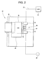
FIGURE 2 is a schematic plan side view illustration of the drawout circuit breaker system ofFigure 1 in the racked-in position; -
FIGURE 3 is a schematic plan side view illustration of the drawout circuit breaker system ofFigure 1 in the test position; -
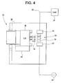
FIGURE 4 is a schematic plan side view illustration of the drawout circuit breaker system ofFigure 1 in the withdrawn or racked-out position; -
FIGURE 5 is a side plan view illustration of the secondary disconnect mechanism ofFigure 2 in the racked-in position; -
FIGURE 6 is a side plan view illustration of the secondary disconnect mechanism ofFigure 3 in the test position; -
FIGURE 7 is a side plan view illustration of the secondary disconnect mechanism ofFigure 4 in the racked-out position; and, -
FIGURE 8 is a partial perspective view illustration of the secondary disconnect mechanism in accordance with the exemplary embodiment; and, -
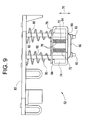
FIGURE 9 is a partial side plan sectional view illustration of the secondary disconnect mechanism ofFigure 8 . -
Figures 1 - 4 illustrate a drawoutcircuit breaker system 20. Thedrawout circuit breaker 20 is coupled between a mainelectrical circuit 22 having a protectedload 24 and apower source 26 such as an electrical utility network. Thedrawout circuit breaker 20 includes ahousing 28. Adoor 30 is coupled to thehousing 28 byhinges 32. Thedoor 30 includes anopening 34 that allows the operator access to acircuit breaker 36 located within thehousing 28. Another opening 38 allows the operator to activate adrawout mechanism 40. Thecircuit breaker 36 is electrically coupled between thepower source 26 and the protectedload 24. - It should be appreciated that the
circuit breaker 36 is illustrated in the exemplary embodiment having a single connection to thepower source 26 and the protectedload 24. However, thecircuit breaker 36 may comprise of multiple electrical phases or connections. Further, thecircuit breaker 36 may be known as a multi-pole circuit breaker having multiple contact arms that connect and disconnected the mainelectrical circuit 22 from thepower source 26. A "multi-pole" circuit breaker the circuit breaker will typically have three or four poles, each carrying a different phase of electricity through thecircuit breaker 36. Further, in the exemplary embodiment, thecircuit breaker 36 is a molded case circuit breaker (MCCB) where the circuit breaker components are housed within an insulated polymer housing. However, but other types of circuit breakers, such as open frame air circuit breakers may also be used. - The
circuit breaker 36 may further include one or more accessories, including but not limited to ashunt trip 46 and an under-voltage accessory 48 for example. Theshunt trip 46 is a device mounted within the circuit breaker that allows an operator to remotely switch the circuit breaker from the on to the off position. Typically, theshunt trip 46 is connected to an external switch (not shown). When the switch is closed, an electromagnetic coil inside the shunt trip energizes and applies a force to the circuit breaker handle. An under-voltage accessory used with circuit protective apparatus to interrupt the circuit current when the systems voltage falls below a predetermined value. Similar to theshunt trip 46, the under-voltage accessory 48 acts upon the circuit breaker mechanism causing the circuit breaker to switch from the on to the off positions when the undesired condition occurs. - Circuit breaker accessories, such as
shut trip 46 and under-voltage accessory 48 for example, require a power source to operate. Further, the power source must be available when the circuit breaker is in certain positions, but disconnected in others. Referring now toFigures 2-4 , the positions of thedrawout system 20 will be described. Thedrawout system 20 is used to allow an operator to physically connect and remove thecircuit breaker 36 into and out of connection with theelectrical circuit 22 without having to manually remove the cabling or other electrical connections. An operator may need to disconnect thecircuit breaker 36 so that downstream maintenance tasks may be performed for example. To accomplish this, thecircuit breaker 36 is mounted to adrawout mechanism 40 as is known in the art. Thedrawout mechanism 40 includes means for moving thecircuit breaker 36 into and out of contact withelectrical contacts inlet contacts 42 connect thecircuit breaker 36 to thepower source 26 while theoutlet contacts 44 provide a connection to theload 24. When thedrawout mechanism 40 moves thecircuit breaker 36 away from thecontacts 42, 44 (Figure 3 ,Figure 4 ), the electrical connection is broken and no electrical power can flow from thepower source 26 to theload 24. - A
secondary disconnect 50 is also coupled to thecircuit breaker 36. Thesecondary disconnect 50 includes amovable portion 52 and astationary portion 54. As will be discussed in more detail below, themovable portion 52 and thestationary portion 54 cooperate to provide electrical power to secondary accessories, such asshunt trip 46 for example, when thecircuit breaker 36 is in the racked-in and test positions, but is disconnected when the circuit breaker is in the racked-out position. It should be appreciated that while thestationary portion 54 and theelectrical contacts - In general, drawout systems have three positions in which the
circuit breaker 36 may be positioned. In the racked-in position illustrated inFigure 2 , thecircuit breaker 36 is coupled to thecontacts circuit breaker 36 is closed. Thecontacts Figure 4 . In the racked-out position, the circuit breaker is disconnected from thecontacts movable portion 52 is disconnected from thestationary portion 54. Further, when in the racked-out position, thedrawout system 20 will typically have an interlock arrangement that prevents thecircuit breaker 36 from being operated. Finally, as illustrated inFigure 3 , intermediate to the racked-in and racked-out positions is what is commonly referred to as the test position. When in the test position, thecircuit breaker 36 is not interlocked and may be operated so that the functions of the circuit breaker may be tested. As will be discussed below, themovable portion 52 and thestationary portion 54 of thesecondary disconnect 50 remain electrically coupled when in the test position and allow the secondary accessories, such asshunt trip 46 to be operated in the test position. - Referring now to
Figures 5-9 , the operations of thesecondary disconnect 50 will be described. The secondary disconnectmovable portion 52 is coupled to thecircuit breaker 36 and moves with the circuit breaker as thecircuit breaker 36 is moved between the positions described above. The movable portion includes maleelectrical connectors electrical connectors electrical contacts 62. Theelectrical contacts 62 are connected to wires (not shown) that electrically connect theelectrical contacts 62 to secondary accessories, such asshunt trip 46 for example. - Spacer frames 64 are positioned between each of the
electrical connectors base plate 66 couples theelectrical connectors electrical connectors circuit breaker 36 by guide pins 68. In the exemplary embodiment, the guide pins 68 are u-shaped pins that are coupled to the spacer frames 64 to allow the spacer frames 68 to move in the direction ofarrow 70. Alternatively, the guide pins 68 may be comprised individual pins rather than a single u-shaped member. An optionalintermediate plate 82 may be coupled to the guide pins 68 and used to mount themovable portion 52 to thecircuit breaker 36. - The spacer frames 64 include a pair of compression springs 72 that are arranged within a generally
hollow portion 74. Thesprings 72 are disposed aboutpins 76 that are coupled between aplate 78 and thespacer frame 64. Theplate 78 is also coupled to guidepin 68 to allow the plate to move with thespacer frame 64. As will be discussed below, the compression springs 72 provide a biasing force to create a positive contact when the circuit breaker is in the racked-in position ofFigure 2 . In one embodiment, the compression springs 72 are sized to provide a small gap between theplate 78 and thesurface 94 of thespacer frame 64. - A
compression spring 80 is disposed about theguide pin 68 between theplate 78 and the bottom of thecircuit breaker 36. Thecompression spring 80 biases thespacer frame 64 away from thecircuit breaker 36. In the exemplary embodiment, thecompression spring 80 is a conical compression spring. Thespring 80 is arranged such that the angle of the spring allows the wire diameter for each turn of the spring to telescope or overlap with the adjacent "row" of the spring as thespring 80 is compressed. As will be discussed below, this provides an advantage in that thespring 80 may be fully compressed to a solid height that is equal to one to two thickness of the wire diameter. In the exemplary embodiment, there are four conical compression springs 80. Each of the conical compression springs 80 is disposed about thelegs 92 of the guide pins 68 - During operation, the circuit breaker is in the racked-in position (
Figure 5 ). When in this position, theelectrical contacts 62 on theelectrical connectors electrical connectors stationary portion 54. When in this position, thecompression spring 80 is fully compressed to approximately its solid height. Thecompression spring 72 is sized to allow compression of thespring 72 once thecompression spring 80 has reached its solid height. This allows thespring 72 to maintain a positive force on theelectrical connectors circuit breaker 36 is in the racked-in position while also minimizing the space needed to fit thesecondary disconnect 50 in the space provided within thehousing 28. The combination of thesprings housing 28 often operates at elevated temperatures due to the heat generated by the flow of electrical current. Due to these elevated temperatures along with high stresses, the conical spring may experience thermal aging or creep issues causing thespring 80 to lose force over time. Thus the combination of thesprings - If the operator desires to disconnect the main
electrical circuit 22 and perform testing on thecircuit breaker 36 accessories, thedrawout mechanism 40 is activated and thecircuit breaker 36 is moved to the test position (Figure 6 ). In this position, thecircuit breaker 36 is disconnected from theinlet contact 42 and theoutlet contact 44 and no electrical power flows from thepower source 26 to theload 24. However, as thecircuit breaker 36 moves, the compression springs 80 expand and applies a force on the spacer frames 64 keeping the maleelectrical connectors electrical connectors compression spring 80 is sized to maintain an adequate force on the electrical connectors to maintain the electrical connection when thecircuit breaker 36 is in the test position. - There are times, such as when maintenance is required on the
drawout system 20 for example, when it is desirable to completely disconnect all electrical power from thecircuit breaker 36 including the secondary accessories. To achieve this, the operator further activates thedrawout mechanism 40 and moves thecircuit breaker 36 to the racked-out position (Figure 7 ). As the circuit breaker continues to move away from theelectrical connectors connectors space frames 64 contact thebottom portion 90 of the guide pins 68. At this point, the travel of theelectrical connectors electrical connectors female connectors circuit breaker 36 reaches the racked-out position. - It should be appreciated that the
secondary disconnect 50 arrangement provides a number of advantages to service personnel and in the manufacture of thedrawout system 20. Thesecondary disconnect 50 allows the manufacturer to reduce the size and space requirements of thedrawout system 20. Thesecondary disconnect 50 also provides a reliable and positive contact between the movable portions and stationary portions. The secondary disconnect further compensates for harsh environmental conditions that would degrade spring performance over time. - This written description uses examples to disclose the invention, including the best mode, and also to enable any person skilled in the art to practice the invention, including making and using any devices or systems and performing any incorporated methods. The patentable scope of the invention is defined by the claims, and may include other examples that occur to those skilled in the art. Such other examples are intended to be within the scope of the claims if they have structural elements that do not differ from the literal language of the claims, or if they include equivalent structural elements with insubstantial differences from the literal languages of the claims.
- Aspects of the present invention are defined in the following numbered clauses:
- 1. A secondary disconnect mechanism for a circuit breaker drawout comprising:
- at least one electrical contact movable between a first position and a second position;
- a first biasing member coupled to said at least one electrical contact, said first biasing member biasing said at least one electrical contact in a first direction; and,
- a second biasing member coupled to said at least one electrical contract, said second biasing member biasing said at least on electrical contact when said at least one electrical contact is in said first position.
- 2. The secondary disconnect mechanism of Clause 1 wherein said first biasing member and said second biasing member are compression springs.
- 3. The secondary disconnect mechanism of Clause 2 wherein said first spring is a conical compression spring.
- 4. The secondary disconnect mechanism of Clause 2 or Clause 3 further comprising:
- a frame coupled to said at least one electrical contact and coupled to said second spring; and,
- a guide pin movably coupled to said frame.
- 5. The secondary disconnect mechanism of any one of the preceding Clauses wherein said second spring is positioned to apply said bias in said first direction.
- 6. The secondary disconnect mechanism of Clause 5 wherein said first spring has a wire diameter and wherein said first spring has a height approximately equal to said first spring wire diameter when said at least one electrical contact is in said first position.
- 7. A secondary disconnect mechanism for a circuit breaker drawout comprising:
- a first electrical connector, a second electrical connector and a third electrical connector arranged in parallel, wherein said first electrical connector, said second electrical connector and said third electrical connector are movable between a first position and a second position;
- a base plate coupled between said first electrical connector, said second electrical connector and said third electrical connector;
- a first frame coupled to said base plate and between said first electrical connector and said second electrical connector;
- a second frame coupled to said base plate and between said second electrical connector and said third electrical connector;
- a first spring is arranged to bias said first frame in a first direction;
- a second spring is arranged to bias said second frame in said first direction;
- a third spring coupled to said first frame and arranged to bias said first frame when said first electrical connector, said second electrical connector and said third electrical connector are in said first position; and,
- a fourth spring coupled to said second frame and arranged to bias said second frame when said first electrical connector, said second electrical connector and said third electrical connector are in said first position.
- 8. The secondary disconnect mechanism of Clause 7 further comprising:
- a first guide pin coupled to said first frame;
- a second guide pin coupled to said second frame.
- 9. The secondary disconnect mechanism of Clause 8 wherein said first spring is disposed about said first guide pin and said second spring is disposed about said second guide pin.
- 10. The secondary disconnect mechanism of any one of clauses 7 to 9 wherein said first spring and said second spring are conical compression springs.
- 11. The secondary disconnect mechanism of Clause 10 wherein said first spring and said second spring have a wire diameter, and wherein said first spring and said second spring have a height of approximately equal to said wire diameter when first electrical connector, said second electrical connector and said third electrical connector are in said first position.
- 12. The secondary disconnect mechanism of Clause 11 wherein said first frame and said second frame each have a generally hollow portion and wherein said third spring is positioned within said first frame hollow portion and said fourth spring is positioned within said second frame hollow portion.
- 13. A drawout mechanism comprising:
- a housing;
- a mechanism within said housing and movable between a first position, a second position and a third position;
- electrical contacts positioned within said housing and operably coupled to said mechanism;
- a plug-in base adjacent to said electrical contacts;
- a circuit breaker coupled to said mechanism, wherein said circuit breaker is electrically connected to said electrical contacts in said first position, and disconnected from said electrical contacts when in said second and third positions;
- a secondary disconnect coupled to said circuit breaker and electrically coupled to said plug-in base when said circuit breaker is in said first position and said second position, said secondary disconnect including:
- an electrical connector;
- a first spring coupled between said circuit breaker and said electrical connector, said first spring arranged to bias said electrical connector towards said first position; and,
- a second spring coupled to said electrical connector, said second spring being arranged to bias said electrical connector when said circuit breaker is in said first position.
- 14. The drawout mechanism of Clause 13 further comprising a guide pin coupled to said circuit breaker, wherein said electrical connector is movably coupled to said guide pin.
- 15. The drawout mechanism of Clause 14 wherein said first spring and said second spring are compression springs
- 16. The drawout mechanism of Clause 15 wherein said first spring is a conical compression spring.
- 17. The drawout mechanism of Clause 16 further comprising:
- a frame movably coupled to said guide pin; and,
- a base plate coupled between said frame and said electrical connector.
- 18. The drawout mechanism of Clause 17 wherein said second spring is positioned within said frame.
- 19. The drawout mechanism of Clause 18 wherein said first spring has a wire diameter and wherein said first spring has a height approximately equal to said wire diameter when said circuit breaker is in said first position.
Claims (15)
- A secondary disconnect mechanism for a circuit breaker drawout comprising:at least one electrical contact movable between a first position and a second position;a first spring coupled to said at least one electrical contact, said first spring biasing said at least one electrical contact in a first direction; and,a second spring coupled to said at least one electrical contract, said second spring biasing said at least on electrical contact when said at least one electrical contact is in said first position.
- The secondary disconnect mechanism of Claim 1 wherein said first spring and said second spring are compression springs.
- The secondary disconnect mechanism of Claim 1 or Claim 2 further comprising:a frame coupled to said at least one electrical contact and coupled to said second spring; and,a guide pin movably coupled to said frame.
- The secondary disconnect mechanism of any one of the preceding Claims wherein said first spring has a wire diameter and wherein said first spring has a height approximately equal to said first spring wire diameter when said at least one electrical contact is in said first position.
- A secondary disconnect mechanism for a circuit breaker drawout comprising:a first electrical connector, a second electrical connector and a third electrical connector arranged in parallel, wherein said first electrical connector, said second electrical connector and said third electrical connector are movable between a first position and a second position;a base plate coupled between said first electrical connector, said second electrical connector and said third electrical connector;a first frame coupled to said base plate and between said first electrical connector and said second electrical connector;a second frame coupled to said base plate and between said second electrical connector and said third electrical connector;a first spring is arranged to bias said first frame in a first direction;a second spring is arranged to bias said second frame in said first direction;a third spring coupled to said first frame and arranged to bias said first frame when said first electrical connector, said second electrical connector and said third electrical connector are in said first position; and,a fourth spring coupled to said second frame and arranged to bias said second frame when said first electrical connector, said second electrical connector and said third electrical connector are in said first position.
- The secondary disconnect mechanism of Claim 5 further comprising:a first guide pin coupled to said first frame;a second guide pin coupled to said second frame.
- The secondary disconnect mechanism of Claim 5 or Claim 6 wherein said first spring is disposed about said first guide pin and said second spring is disposed about said second guide pin.
- The secondary disconnect mechanism of any one of Claims 5 to 7 wherein said first spring and said second spring have a wire diameter, and wherein said first spring and said second spring have a height of approximately equal to said wire diameter when first electrical connector, said second electrical connector and said third electrical connector are in said first position.
- The secondary disconnect mechanism of any one of Claims 5 to 8 wherein said first frame and said second frame each have a generally hollow portion and wherein said third spring is positioned within said first frame hollow portion and said fourth spring is positioned within said second frame hollow portion.
- A drawout mechanism comprising:a housing;a mechanism within said housing and movable between a first position, a second position and a third position;electrical contacts positioned within said housing and operably coupled to said mechanism;a plug-in base adjacent to said electrical contacts;a circuit breaker coupled to said mechanism, wherein said circuit breaker is electrically connected to said electrical contacts in said first position, and disconnected from said electrical contacts when in said second and third positions;a secondary disconnect coupled to said circuit breaker and electrically coupled to said plug-in base when said circuit breaker is in said first position and said second position, said secondary disconnect including:an electrical connector;a first spring coupled between said circuit breaker and said electrical connector, said first spring arranged to bias said electrical connector towards said first position; and,a second spring coupled to said electrical connector, said second spring being arranged to bias said electrical connector when said circuit breaker is in said first position.
- The drawout mechanism of Claim 10 further comprising a guide pin coupled to said circuit breaker, wherein said electrical connector is movably coupled to said guide pin.
- The drawout mechanism of Claim 10 or Claim 11 wherein said first spring and said second spring are compression springs
- The drawout mechanism of any one of Claims 10 to 12 further comprising:a frame movably coupled to said guide pin; and,a base plate coupled between said frame and said electrical connector.
- The drawout mechanism of Claim 13 wherein said second spring is positioned within said frame.
- The drawout mechanism of any one of Claims 10 to 14 wherein said first spring has a wire diameter and wherein said first spring has a height approximately equal to said wire diameter when said circuit breaker is in said first position.
Applications Claiming Priority (1)
| Application Number | Priority Date | Filing Date | Title |
|---|---|---|---|
| PL385808A PL385808A1 (en) | 2008-08-01 | 2008-08-01 | Secondary disconnection mechanism for the drawable circuit interrupter and the draw-out mechanism |
Publications (3)
| Publication Number | Publication Date |
|---|---|
| EP2149947A2 true EP2149947A2 (en) | 2010-02-03 |
| EP2149947A3 EP2149947A3 (en) | 2010-10-27 |
| EP2149947B1 EP2149947B1 (en) | 2016-05-25 |
Family
ID=41343194
Family Applications (1)
| Application Number | Title | Priority Date | Filing Date |
|---|---|---|---|
| EP09166449.0A Active EP2149947B1 (en) | 2008-08-01 | 2009-07-27 | Secondary disconnect for circuit breaker drawout system |
Country Status (4)
| Country | Link |
|---|---|
| US (1) | US7927155B2 (en) |
| EP (1) | EP2149947B1 (en) |
| CN (1) | CN101651067B (en) |
| PL (1) | PL385808A1 (en) |
Cited By (2)
| Publication number | Priority date | Publication date | Assignee | Title |
|---|---|---|---|---|
| WO2011107172A1 (en) * | 2010-03-05 | 2011-09-09 | Siemens Aktiengesellschaft | Withdrawable unit for a switch cabinet |
| US9929546B2 (en) * | 2014-10-03 | 2018-03-27 | Eaton Intelligent Power Limited | Electrical system and support assembly therefor |
Families Citing this family (13)
| Publication number | Priority date | Publication date | Assignee | Title |
|---|---|---|---|---|
| PL385646A1 (en) * | 2008-07-11 | 2010-01-18 | General Electric Company | Pull-out door interface for a circiut interruptor |
| DE102010039934B4 (en) * | 2010-08-30 | 2017-02-02 | Siemens Aktiengesellschaft | Recording module for receiving a circuit breaker, circuit breaker system and method for coupling a power switch with a receiving module |
| US8497439B2 (en) * | 2011-03-10 | 2013-07-30 | General Electric Company | Self-aligning secondary disconnect device for electrical switchgear |
| US8704114B2 (en) * | 2011-05-05 | 2014-04-22 | General Electric Company | Interlocked circuit breakers |
| US8907237B2 (en) * | 2012-11-13 | 2014-12-09 | Eaton Corporation | Floating contact assembly for switchgear |
| CN103001135B (en) * | 2012-12-19 | 2015-08-19 | 镇江赛尔尼柯电器有限公司 | 1/2 drawer unit of drawer-type distribution box |
| GB201410728D0 (en) * | 2014-06-16 | 2014-07-30 | Eaton Ind Netherlands Bv | Retraction mechanism |
| US9753088B2 (en) | 2014-11-03 | 2017-09-05 | Eaton Corporation | Portable diagnostic apparatus for testing circuit breakers |
| US9742164B2 (en) | 2015-06-16 | 2017-08-22 | General Electric Company | Secondary disconnect assembly for a switching device |
| CN107293986B (en) * | 2017-08-11 | 2019-05-24 | 山东翔晟电力工程有限公司 | A kind of machinery drawer type Electromagnetic Control electric power cabinet |
| CN107293985B (en) * | 2017-08-11 | 2019-03-29 | 江苏国控电力设备有限公司 | A kind of Electromagnetic Control drawer type electric power cabinet |
| CN208142678U (en) * | 2018-04-26 | 2018-11-23 | Abb股份公司 | Pull-out type base module for switch |
| EP4024637B1 (en) * | 2020-12-29 | 2025-05-07 | Schneider Electric USA, Inc. | Racking on circuit breaker with integrated automatic secondary plug |
Family Cites Families (16)
| Publication number | Priority date | Publication date | Assignee | Title |
|---|---|---|---|---|
| US1804590A (en) * | 1926-04-12 | 1931-05-12 | Westinghouse Electric & Mfg Co | Switch mechanisms |
| US2129723A (en) * | 1936-09-29 | 1938-09-13 | Roller Smith Company | Circuit breaker |
| US2767266A (en) * | 1954-03-25 | 1956-10-16 | Fed Electric Prod Co | Draw-out switch gear |
| US2794873A (en) * | 1954-10-28 | 1957-06-04 | Allis Chalmers Mfg Co | Switching device with l-shaped contactor bars |
| US2921998A (en) * | 1958-05-02 | 1960-01-19 | Ite Circuit Breaker Ltd | Four position drawout circuit breaker |
| US3197583A (en) * | 1962-12-19 | 1965-07-27 | Allis Chalmers Mfg Co | Electrical connector for secondary circuits |
| US3440371A (en) * | 1967-03-10 | 1969-04-22 | Gen Electric | Jackscrew type racking mechanism for drawout switchgear |
| US3469043A (en) * | 1967-07-19 | 1969-09-23 | Ite Imperial Corp | Dual mode circuit breaker withdrawal mechanism |
| US4012610A (en) * | 1975-04-14 | 1977-03-15 | General Electric Company | Drawout apparatus having improved trip interlock |
| US4139748A (en) * | 1977-01-05 | 1979-02-13 | Westinghouse Electric Corp. | Secondary contacts for drawout switchgear |
| US4121067A (en) * | 1977-01-05 | 1978-10-17 | Westinghouse Electric Corp. | Contact structure for drawout switchgear |
| US4477701A (en) * | 1982-11-10 | 1984-10-16 | General Electric Company | Secondary disconnect plugs for programmable circuit breakers |
| US4565908A (en) * | 1984-12-12 | 1986-01-21 | Westinghouse Electric Corp. | Drawout switchgear apparatus with retractable shutter mechanism for terminal stabs |
| US5417595A (en) * | 1993-04-22 | 1995-05-23 | Applied Robotics, Inc. | Method and apparatus for frequently connecting and disconnecting signal cables |
| US5434369A (en) * | 1994-02-14 | 1995-07-18 | Abb Power T & D Company, Inc. | Automated secondary disconnect mechanism for electrical switchgear |
| US5915985A (en) * | 1997-05-05 | 1999-06-29 | The Whitaker Corporation | Traveling electrical connector |
-
2008
- 2008-08-01 PL PL385808A patent/PL385808A1/en not_active Application Discontinuation
- 2008-09-11 US US12/208,449 patent/US7927155B2/en active Active
-
2009
- 2009-07-27 EP EP09166449.0A patent/EP2149947B1/en active Active
- 2009-07-30 CN CN200910159239.2A patent/CN101651067B/en active Active
Cited By (2)
| Publication number | Priority date | Publication date | Assignee | Title |
|---|---|---|---|---|
| WO2011107172A1 (en) * | 2010-03-05 | 2011-09-09 | Siemens Aktiengesellschaft | Withdrawable unit for a switch cabinet |
| US9929546B2 (en) * | 2014-10-03 | 2018-03-27 | Eaton Intelligent Power Limited | Electrical system and support assembly therefor |
Also Published As
| Publication number | Publication date |
|---|---|
| US7927155B2 (en) | 2011-04-19 |
| CN101651067A (en) | 2010-02-17 |
| EP2149947A3 (en) | 2010-10-27 |
| CN101651067B (en) | 2015-08-19 |
| US20100025202A1 (en) | 2010-02-04 |
| PL385808A1 (en) | 2010-02-15 |
| EP2149947B1 (en) | 2016-05-25 |
Similar Documents
| Publication | Publication Date | Title |
|---|---|---|
| EP2149947B1 (en) | Secondary disconnect for circuit breaker drawout system | |
| EP1903592B1 (en) | Vacuum insulated switchgear | |
| US9224548B2 (en) | Disconnect switch including fusible switching disconnect modules | |
| US9576751B1 (en) | Motorized vacuum isolation switch | |
| US6179637B1 (en) | Assembly and method for automatically providing secondary connections for switchgear | |
| EP2110829B1 (en) | A spring discharge mechanism for circuit breaker | |
| EP2466609B1 (en) | Discharge mechanism for circuit breaker | |
| US7772945B2 (en) | Electrical switching device | |
| US11996248B2 (en) | Scissor-link for actuator pull-open function | |
| US9742164B2 (en) | Secondary disconnect assembly for a switching device | |
| KR101293481B1 (en) | Mechanical interlock between vcb and breaker | |
| CN101339867B (en) | Electrical switching apparatus and trip bar therefor | |
| WO2008100510A1 (en) | Livebreak fuse removal assembly for deadfront electrical apparatus | |
| US9797952B2 (en) | Safety test switch with actuation lever | |
| WO2019183964A1 (en) | An air insulated switchgear and an electrical system comprising the same | |
| US7911768B2 (en) | Drawout door interface for circuit breaker | |
| US20110037543A1 (en) | Electrical switching device | |
| WO2015180795A1 (en) | Assembly for a withdrawable switching device and related switching device | |
| US9170293B2 (en) | Power line indicator accessory for fusible circuit protection device array | |
| EP2144342B1 (en) | Drawout door interface for circuit breaker | |
| KR101831850B1 (en) | 25.8KV bypass built-in variable load break switch | |
| CN120341705A (en) | An intelligent switch cabinet based on maintenance power-off protection and maintenance method thereof | |
| KR20090109487A (en) | Spring release mechanism for circuit breakers | |
| KR20200124964A (en) | Device for transform contact and circuit breaker using the same | |
| WO2013144969A2 (en) | An improved three-phase disconnector |
Legal Events
| Date | Code | Title | Description |
|---|---|---|---|
| PUAI | Public reference made under article 153(3) epc to a published international application that has entered the european phase |
Free format text: ORIGINAL CODE: 0009012 |
|
| AK | Designated contracting states |
Kind code of ref document: A2 Designated state(s): AT BE BG CH CY CZ DE DK EE ES FI FR GB GR HR HU IE IS IT LI LT LU LV MC MK MT NL NO PL PT RO SE SI SK SM TR |
|
| AX | Request for extension of the european patent |
Extension state: AL BA RS |
|
| PUAL | Search report despatched |
Free format text: ORIGINAL CODE: 0009013 |
|
| AK | Designated contracting states |
Kind code of ref document: A3 Designated state(s): AT BE BG CH CY CZ DE DK EE ES FI FR GB GR HR HU IE IS IT LI LT LU LV MC MK MT NL NO PL PT RO SE SI SK SM TR |
|
| AX | Request for extension of the european patent |
Extension state: AL BA RS |
|
| 17P | Request for examination filed |
Effective date: 20110427 |
|
| GRAP | Despatch of communication of intention to grant a patent |
Free format text: ORIGINAL CODE: EPIDOSNIGR1 |
|
| INTG | Intention to grant announced |
Effective date: 20160205 |
|
| RIN1 | Information on inventor provided before grant (corrected) |
Inventor name: POMMERENCKE, LARS Inventor name: MITTU, MAHADEVA Inventor name: SRINIVASAN, KARTHIKEYAN Inventor name: SKRUDLIK, ADAM Inventor name: IGNASIAK, TOMASZ |
|
| GRAS | Grant fee paid |
Free format text: ORIGINAL CODE: EPIDOSNIGR3 |
|
| GRAA | (expected) grant |
Free format text: ORIGINAL CODE: 0009210 |
|
| AK | Designated contracting states |
Kind code of ref document: B1 Designated state(s): AT BE BG CH CY CZ DE DK EE ES FI FR GB GR HR HU IE IS IT LI LT LU LV MC MK MT NL NO PL PT RO SE SI SK SM TR |
|
| REG | Reference to a national code |
Ref country code: GB Ref legal event code: FG4D |
|
| REG | Reference to a national code |
Ref country code: CH Ref legal event code: EP |
|
| REG | Reference to a national code |
Ref country code: IE Ref legal event code: FG4D Ref country code: AT Ref legal event code: REF Ref document number: 803028 Country of ref document: AT Kind code of ref document: T Effective date: 20160615 |
|
| REG | Reference to a national code |
Ref country code: DE Ref legal event code: R096 Ref document number: 602009038821 Country of ref document: DE |
|
| REG | Reference to a national code |
Ref country code: LT Ref legal event code: MG4D |
|
| REG | Reference to a national code |
Ref country code: NL Ref legal event code: MP Effective date: 20160525 |
|
| PG25 | Lapsed in a contracting state [announced via postgrant information from national office to epo] |
Ref country code: LT Free format text: LAPSE BECAUSE OF FAILURE TO SUBMIT A TRANSLATION OF THE DESCRIPTION OR TO PAY THE FEE WITHIN THE PRESCRIBED TIME-LIMIT Effective date: 20160525 Ref country code: FI Free format text: LAPSE BECAUSE OF FAILURE TO SUBMIT A TRANSLATION OF THE DESCRIPTION OR TO PAY THE FEE WITHIN THE PRESCRIBED TIME-LIMIT Effective date: 20160525 Ref country code: NO Free format text: LAPSE BECAUSE OF FAILURE TO SUBMIT A TRANSLATION OF THE DESCRIPTION OR TO PAY THE FEE WITHIN THE PRESCRIBED TIME-LIMIT Effective date: 20160825 Ref country code: NL Free format text: LAPSE BECAUSE OF FAILURE TO SUBMIT A TRANSLATION OF THE DESCRIPTION OR TO PAY THE FEE WITHIN THE PRESCRIBED TIME-LIMIT Effective date: 20160525 |
|
| REG | Reference to a national code |
Ref country code: AT Ref legal event code: MK05 Ref document number: 803028 Country of ref document: AT Kind code of ref document: T Effective date: 20160525 |
|
| PG25 | Lapsed in a contracting state [announced via postgrant information from national office to epo] |
Ref country code: LV Free format text: LAPSE BECAUSE OF FAILURE TO SUBMIT A TRANSLATION OF THE DESCRIPTION OR TO PAY THE FEE WITHIN THE PRESCRIBED TIME-LIMIT Effective date: 20160525 Ref country code: ES Free format text: LAPSE BECAUSE OF FAILURE TO SUBMIT A TRANSLATION OF THE DESCRIPTION OR TO PAY THE FEE WITHIN THE PRESCRIBED TIME-LIMIT Effective date: 20160525 Ref country code: GR Free format text: LAPSE BECAUSE OF FAILURE TO SUBMIT A TRANSLATION OF THE DESCRIPTION OR TO PAY THE FEE WITHIN THE PRESCRIBED TIME-LIMIT Effective date: 20160826 Ref country code: HR Free format text: LAPSE BECAUSE OF FAILURE TO SUBMIT A TRANSLATION OF THE DESCRIPTION OR TO PAY THE FEE WITHIN THE PRESCRIBED TIME-LIMIT Effective date: 20160525 Ref country code: SE Free format text: LAPSE BECAUSE OF FAILURE TO SUBMIT A TRANSLATION OF THE DESCRIPTION OR TO PAY THE FEE WITHIN THE PRESCRIBED TIME-LIMIT Effective date: 20160525 Ref country code: PT Free format text: LAPSE BECAUSE OF FAILURE TO SUBMIT A TRANSLATION OF THE DESCRIPTION OR TO PAY THE FEE WITHIN THE PRESCRIBED TIME-LIMIT Effective date: 20160926 |
|
| PG25 | Lapsed in a contracting state [announced via postgrant information from national office to epo] |
Ref country code: BE Free format text: LAPSE BECAUSE OF NON-PAYMENT OF DUE FEES Effective date: 20160731 Ref country code: IT Free format text: LAPSE BECAUSE OF FAILURE TO SUBMIT A TRANSLATION OF THE DESCRIPTION OR TO PAY THE FEE WITHIN THE PRESCRIBED TIME-LIMIT Effective date: 20160525 |
|
| PG25 | Lapsed in a contracting state [announced via postgrant information from national office to epo] |
Ref country code: EE Free format text: LAPSE BECAUSE OF FAILURE TO SUBMIT A TRANSLATION OF THE DESCRIPTION OR TO PAY THE FEE WITHIN THE PRESCRIBED TIME-LIMIT Effective date: 20160525 Ref country code: CZ Free format text: LAPSE BECAUSE OF FAILURE TO SUBMIT A TRANSLATION OF THE DESCRIPTION OR TO PAY THE FEE WITHIN THE PRESCRIBED TIME-LIMIT Effective date: 20160525 Ref country code: SK Free format text: LAPSE BECAUSE OF FAILURE TO SUBMIT A TRANSLATION OF THE DESCRIPTION OR TO PAY THE FEE WITHIN THE PRESCRIBED TIME-LIMIT Effective date: 20160525 Ref country code: DK Free format text: LAPSE BECAUSE OF FAILURE TO SUBMIT A TRANSLATION OF THE DESCRIPTION OR TO PAY THE FEE WITHIN THE PRESCRIBED TIME-LIMIT Effective date: 20160525 Ref country code: RO Free format text: LAPSE BECAUSE OF FAILURE TO SUBMIT A TRANSLATION OF THE DESCRIPTION OR TO PAY THE FEE WITHIN THE PRESCRIBED TIME-LIMIT Effective date: 20160525 |
|
| PG25 | Lapsed in a contracting state [announced via postgrant information from national office to epo] |
Ref country code: PL Free format text: LAPSE BECAUSE OF FAILURE TO SUBMIT A TRANSLATION OF THE DESCRIPTION OR TO PAY THE FEE WITHIN THE PRESCRIBED TIME-LIMIT Effective date: 20160525 Ref country code: SM Free format text: LAPSE BECAUSE OF FAILURE TO SUBMIT A TRANSLATION OF THE DESCRIPTION OR TO PAY THE FEE WITHIN THE PRESCRIBED TIME-LIMIT Effective date: 20160525 Ref country code: BE Free format text: LAPSE BECAUSE OF FAILURE TO SUBMIT A TRANSLATION OF THE DESCRIPTION OR TO PAY THE FEE WITHIN THE PRESCRIBED TIME-LIMIT Effective date: 20160525 Ref country code: AT Free format text: LAPSE BECAUSE OF FAILURE TO SUBMIT A TRANSLATION OF THE DESCRIPTION OR TO PAY THE FEE WITHIN THE PRESCRIBED TIME-LIMIT Effective date: 20160525 |
|
| REG | Reference to a national code |
Ref country code: DE Ref legal event code: R097 Ref document number: 602009038821 Country of ref document: DE Ref country code: CH Ref legal event code: PL |
|
| PG25 | Lapsed in a contracting state [announced via postgrant information from national office to epo] |
Ref country code: MC Free format text: LAPSE BECAUSE OF FAILURE TO SUBMIT A TRANSLATION OF THE DESCRIPTION OR TO PAY THE FEE WITHIN THE PRESCRIBED TIME-LIMIT Effective date: 20160525 |
|
| PLBE | No opposition filed within time limit |
Free format text: ORIGINAL CODE: 0009261 |
|
| STAA | Information on the status of an ep patent application or granted ep patent |
Free format text: STATUS: NO OPPOSITION FILED WITHIN TIME LIMIT |
|
| GBPC | Gb: european patent ceased through non-payment of renewal fee |
Effective date: 20160825 |
|
| PG25 | Lapsed in a contracting state [announced via postgrant information from national office to epo] |
Ref country code: LI Free format text: LAPSE BECAUSE OF NON-PAYMENT OF DUE FEES Effective date: 20160731 Ref country code: FR Free format text: LAPSE BECAUSE OF NON-PAYMENT OF DUE FEES Effective date: 20160801 Ref country code: CH Free format text: LAPSE BECAUSE OF NON-PAYMENT OF DUE FEES Effective date: 20160731 |
|
| REG | Reference to a national code |
Ref country code: FR Ref legal event code: ST Effective date: 20170331 |
|
| 26N | No opposition filed |
Effective date: 20170228 |
|
| REG | Reference to a national code |
Ref country code: IE Ref legal event code: MM4A |
|
| PG25 | Lapsed in a contracting state [announced via postgrant information from national office to epo] |
Ref country code: SI Free format text: LAPSE BECAUSE OF FAILURE TO SUBMIT A TRANSLATION OF THE DESCRIPTION OR TO PAY THE FEE WITHIN THE PRESCRIBED TIME-LIMIT Effective date: 20160525 |
|
| PG25 | Lapsed in a contracting state [announced via postgrant information from national office to epo] |
Ref country code: IE Free format text: LAPSE BECAUSE OF NON-PAYMENT OF DUE FEES Effective date: 20160727 Ref country code: GB Free format text: LAPSE BECAUSE OF NON-PAYMENT OF DUE FEES Effective date: 20160825 |
|
| PG25 | Lapsed in a contracting state [announced via postgrant information from national office to epo] |
Ref country code: LU Free format text: LAPSE BECAUSE OF NON-PAYMENT OF DUE FEES Effective date: 20160727 |
|
| PG25 | Lapsed in a contracting state [announced via postgrant information from national office to epo] |
Ref country code: CY Free format text: LAPSE BECAUSE OF FAILURE TO SUBMIT A TRANSLATION OF THE DESCRIPTION OR TO PAY THE FEE WITHIN THE PRESCRIBED TIME-LIMIT Effective date: 20160525 Ref country code: HU Free format text: LAPSE BECAUSE OF FAILURE TO SUBMIT A TRANSLATION OF THE DESCRIPTION OR TO PAY THE FEE WITHIN THE PRESCRIBED TIME-LIMIT; INVALID AB INITIO Effective date: 20090727 |
|
| PG25 | Lapsed in a contracting state [announced via postgrant information from national office to epo] |
Ref country code: TR Free format text: LAPSE BECAUSE OF FAILURE TO SUBMIT A TRANSLATION OF THE DESCRIPTION OR TO PAY THE FEE WITHIN THE PRESCRIBED TIME-LIMIT Effective date: 20160525 Ref country code: MK Free format text: LAPSE BECAUSE OF FAILURE TO SUBMIT A TRANSLATION OF THE DESCRIPTION OR TO PAY THE FEE WITHIN THE PRESCRIBED TIME-LIMIT Effective date: 20160525 Ref country code: MT Free format text: LAPSE BECAUSE OF NON-PAYMENT OF DUE FEES Effective date: 20160731 Ref country code: IS Free format text: LAPSE BECAUSE OF FAILURE TO SUBMIT A TRANSLATION OF THE DESCRIPTION OR TO PAY THE FEE WITHIN THE PRESCRIBED TIME-LIMIT Effective date: 20160525 |
|
| PG25 | Lapsed in a contracting state [announced via postgrant information from national office to epo] |
Ref country code: BG Free format text: LAPSE BECAUSE OF FAILURE TO SUBMIT A TRANSLATION OF THE DESCRIPTION OR TO PAY THE FEE WITHIN THE PRESCRIBED TIME-LIMIT Effective date: 20160525 |
|
| REG | Reference to a national code |
Ref country code: DE Ref legal event code: R081 Ref document number: 602009038821 Country of ref document: DE Owner name: ABB S.P.A., IT Free format text: FORMER OWNER: GENERAL ELECTRIC COMPANY, SCHENECTADY, NY, US Ref country code: DE Ref legal event code: R081 Ref document number: 602009038821 Country of ref document: DE Owner name: ABB SCHWEIZ AG, CH Free format text: FORMER OWNER: GENERAL ELECTRIC COMPANY, SCHENECTADY, N.Y., US Ref country code: DE Ref legal event code: R081 Ref document number: 602009038821 Country of ref document: DE Owner name: ABB SCHWEIZ AG, CH Free format text: FORMER OWNER: GENERAL ELECTRIC COMPANY, SCHENECTADY, NY, US |
|
| REG | Reference to a national code |
Ref country code: DE Ref legal event code: R081 Ref document number: 602009038821 Country of ref document: DE Owner name: ABB S.P.A., IT Free format text: FORMER OWNER: ABB SCHWEIZ AG, BADEN, CH Ref country code: DE Ref legal event code: R082 Ref document number: 602009038821 Country of ref document: DE Representative=s name: DENNEMEYER & ASSOCIATES S.A., DE |
|
| PGFP | Annual fee paid to national office [announced via postgrant information from national office to epo] |
Ref country code: DE Payment date: 20250722 Year of fee payment: 17 |