EP2149870A2 - LED driver circuit and the method thereof - Google Patents
LED driver circuit and the method thereof Download PDFInfo
- Publication number
- EP2149870A2 EP2149870A2 EP09166565A EP09166565A EP2149870A2 EP 2149870 A2 EP2149870 A2 EP 2149870A2 EP 09166565 A EP09166565 A EP 09166565A EP 09166565 A EP09166565 A EP 09166565A EP 2149870 A2 EP2149870 A2 EP 2149870A2
- Authority
- EP
- European Patent Office
- Prior art keywords
- leds
- shift register
- fault
- fault information
- driver circuit
- Prior art date
- Legal status (The legal status is an assumption and is not a legal conclusion. Google has not performed a legal analysis and makes no representation as to the accuracy of the status listed.)
- Withdrawn
Links
Images


Classifications
-
- G—PHYSICS
- G09—EDUCATION; CRYPTOGRAPHY; DISPLAY; ADVERTISING; SEALS
- G09G—ARRANGEMENTS OR CIRCUITS FOR CONTROL OF INDICATING DEVICES USING STATIC MEANS TO PRESENT VARIABLE INFORMATION
- G09G3/00—Control arrangements or circuits, of interest only in connection with visual indicators other than cathode-ray tubes
- G09G3/006—Electronic inspection or testing of displays and display drivers, e.g. of LED or LCD displays
-
- G—PHYSICS
- G09—EDUCATION; CRYPTOGRAPHY; DISPLAY; ADVERTISING; SEALS
- G09G—ARRANGEMENTS OR CIRCUITS FOR CONTROL OF INDICATING DEVICES USING STATIC MEANS TO PRESENT VARIABLE INFORMATION
- G09G3/00—Control arrangements or circuits, of interest only in connection with visual indicators other than cathode-ray tubes
- G09G3/04—Control arrangements or circuits, of interest only in connection with visual indicators other than cathode-ray tubes for presentation of a single character by selection from a plurality of characters, or by composing the character by combination of individual elements, e.g. segments using a combination of such display devices for composing words, rows or the like, in a frame with fixed character positions
- G09G3/06—Control arrangements or circuits, of interest only in connection with visual indicators other than cathode-ray tubes for presentation of a single character by selection from a plurality of characters, or by composing the character by combination of individual elements, e.g. segments using a combination of such display devices for composing words, rows or the like, in a frame with fixed character positions using controlled light sources
- G09G3/12—Control arrangements or circuits, of interest only in connection with visual indicators other than cathode-ray tubes for presentation of a single character by selection from a plurality of characters, or by composing the character by combination of individual elements, e.g. segments using a combination of such display devices for composing words, rows or the like, in a frame with fixed character positions using controlled light sources using electroluminescent elements
- G09G3/14—Semiconductor devices, e.g. diodes
-
- G—PHYSICS
- G09—EDUCATION; CRYPTOGRAPHY; DISPLAY; ADVERTISING; SEALS
- G09G—ARRANGEMENTS OR CIRCUITS FOR CONTROL OF INDICATING DEVICES USING STATIC MEANS TO PRESENT VARIABLE INFORMATION
- G09G3/00—Control arrangements or circuits, of interest only in connection with visual indicators other than cathode-ray tubes
- G09G3/20—Control arrangements or circuits, of interest only in connection with visual indicators other than cathode-ray tubes for presentation of an assembly of a number of characters, e.g. a page, by composing the assembly by combination of individual elements arranged in a matrix no fixed position being assigned to or needed to be assigned to the individual characters or partial characters
- G09G3/2085—Special arrangements for addressing the individual elements of the matrix, other than by driving respective rows and columns in combination
-
- G—PHYSICS
- G09—EDUCATION; CRYPTOGRAPHY; DISPLAY; ADVERTISING; SEALS
- G09G—ARRANGEMENTS OR CIRCUITS FOR CONTROL OF INDICATING DEVICES USING STATIC MEANS TO PRESENT VARIABLE INFORMATION
- G09G3/00—Control arrangements or circuits, of interest only in connection with visual indicators other than cathode-ray tubes
- G09G3/20—Control arrangements or circuits, of interest only in connection with visual indicators other than cathode-ray tubes for presentation of an assembly of a number of characters, e.g. a page, by composing the assembly by combination of individual elements arranged in a matrix no fixed position being assigned to or needed to be assigned to the individual characters or partial characters
- G09G3/22—Control arrangements or circuits, of interest only in connection with visual indicators other than cathode-ray tubes for presentation of an assembly of a number of characters, e.g. a page, by composing the assembly by combination of individual elements arranged in a matrix no fixed position being assigned to or needed to be assigned to the individual characters or partial characters using controlled light sources
- G09G3/30—Control arrangements or circuits, of interest only in connection with visual indicators other than cathode-ray tubes for presentation of an assembly of a number of characters, e.g. a page, by composing the assembly by combination of individual elements arranged in a matrix no fixed position being assigned to or needed to be assigned to the individual characters or partial characters using controlled light sources using electroluminescent panels
- G09G3/32—Control arrangements or circuits, of interest only in connection with visual indicators other than cathode-ray tubes for presentation of an assembly of a number of characters, e.g. a page, by composing the assembly by combination of individual elements arranged in a matrix no fixed position being assigned to or needed to be assigned to the individual characters or partial characters using controlled light sources using electroluminescent panels semiconductive, e.g. using light-emitting diodes [LED]
-
- G—PHYSICS
- G09—EDUCATION; CRYPTOGRAPHY; DISPLAY; ADVERTISING; SEALS
- G09G—ARRANGEMENTS OR CIRCUITS FOR CONTROL OF INDICATING DEVICES USING STATIC MEANS TO PRESENT VARIABLE INFORMATION
- G09G2310/00—Command of the display device
- G09G2310/02—Addressing, scanning or driving the display screen or processing steps related thereto
- G09G2310/0264—Details of driving circuits
- G09G2310/0275—Details of drivers for data electrodes, other than drivers for liquid crystal, plasma or OLED displays, not related to handling digital grey scale data or to communication of data to the pixels by means of a current
-
- G—PHYSICS
- G09—EDUCATION; CRYPTOGRAPHY; DISPLAY; ADVERTISING; SEALS
- G09G—ARRANGEMENTS OR CIRCUITS FOR CONTROL OF INDICATING DEVICES USING STATIC MEANS TO PRESENT VARIABLE INFORMATION
- G09G2330/00—Aspects of power supply; Aspects of display protection and defect management
- G09G2330/08—Fault-tolerant or redundant circuits, or circuits in which repair of defects is prepared
-
- G—PHYSICS
- G09—EDUCATION; CRYPTOGRAPHY; DISPLAY; ADVERTISING; SEALS
- G09G—ARRANGEMENTS OR CIRCUITS FOR CONTROL OF INDICATING DEVICES USING STATIC MEANS TO PRESENT VARIABLE INFORMATION
- G09G2330/00—Aspects of power supply; Aspects of display protection and defect management
- G09G2330/10—Dealing with defective pixels
-
- G—PHYSICS
- G09—EDUCATION; CRYPTOGRAPHY; DISPLAY; ADVERTISING; SEALS
- G09G—ARRANGEMENTS OR CIRCUITS FOR CONTROL OF INDICATING DEVICES USING STATIC MEANS TO PRESENT VARIABLE INFORMATION
- G09G2380/00—Specific applications
- G09G2380/06—Remotely controlled electronic signs other than labels
Definitions
- the present invention relates to a driver circuit and the method thereof, and more particularly, to an LED driver circuit and the method thereof.
- LEDs consume less power, have longer lifetime and are more durable. Therefore, most indicator devices nowadays, such as traffic signs and commercial billboards, are implemented by LEDs. However, since a large number of those large indicator devices are placed outdoors, there are various sources of hazard, such as weather, animals colliding with them, or even droppings, that can damage such LED indicator devices. Unfortunately, conventional LED indicator devices seldom exhibit fault detection mechanism. Therefore, when LED indicator device are damaged, the control device, such as a control-end processor, has no knowledge of the location and the number of the damaged LEDs, and only by human eyes can such information be observed. Since the height of many modern LED indicator devices are over tens of meters, it requires maintenance personnel to climb up high to confirm information on the damaged LED indicator device, which is an arduous task and costs a lot of money.
- FIG. 1 shows a conventional LED driver circuit 100, which is connected to a control-end processor 200 and serves as the driver for a plurality of LEDs 400.
- the LED driver circuit 100 comprises a shift register 110, a plurality of latches 120, a plurality of driver units 130, a plurality of comparators 140, a plurality of state registers 150 and a state switching circuit 160, wherein the number of the flip-flops in the shift register 110, the number of the plurality of latches 120, the number of the plurality of driver units 130 and the number of the plurality of LEDs 400 are the same.
- the input signals of the LED driver circuit 100 include an input data, a latch signal, a switch signal and a clock signal.
- the output signal of the LED driver circuit 100 includes an output data.
- the input terminal of the LED driver circuit 100 for the input data is connected to the first flip-flop of the shift register 110.
- the output terminal of the LED driver circuit 100 for the output data is connected to the last flip-flop of the shift register 110.
- the state switching circuit 160 determines the status of the LED driver circuit 100 according to the latch signal and the switch signal.
- the LED driver circuit 100 receives display signals from the control-end processor 200.
- the received display signals are then serially stored in the shift register 110.
- the data stored in the shift register 110 is then outputted to and stored in the plurality of latches 120.
- the output terminals of the plurality of latches 120 are connected to the plurality of driver units 130 respectively.
- the plurality of driver units 130 have their output terminals connected to, and accordingly drive, the plurality of LEDs 400.
- the LED driver circuit 100 When in a debug mode, the LED driver circuit 100 receives fault-detecting signals (such as the signals of which the bits are all Os or all 1s) from the control-end processor 200. The received fault-detecting signals are then serially stored in the shift register 110. When the storing process of the fault-detecting signals is complete, the data stored in the shift register 110 is then outputted to and stored in the plurality of latches 120 so as to be the input signal for the plurality of driver units 130.
- the input terminals of the plurality of comparators 140 are respectively connected to the output terminals of the plurality of LEDs 400 and a reference voltage. The output signals of the comparators 140 indicate whether the plurality of LEDs 400 are in fault state.
- the plurality of state registers 150 store the comparison results of the plurality of comparators 140, and then stores such results to the shift register 110 at a later time such that the results can be outputted and transmitted back to the control-end processor 200.
- the control-end processor 200 obtains the fault information of the plurality of LEDs 400 according to the comparison results. For instance, if the fault-detecting signal is a signal of which the bits are all 1s, which should turn on all the plurality of LEDs 400, and the comparison results contain bits of "0", then the control-end processor 200 determines that the LEDs 400 at the corresponding locations are faulty.
- FIG. 2 shows the waveforms of the input and output signals of the LED driver circuit 100.
- the clock signal controls the input operation of the shift register 110.
- the display signals are serially stored into the shift register 110.
- the output signals of the LED driver circuit 100 are redundant data.
- a pulse of the latch signal triggers the data stored in the shift register 110 to be stored into the plurality of latches 120.
- the switch signal then switches to low to activate the plurality of driver units 130, and the plurality of LEDs 400 are driven thereby according to the data stored in the plurality of latches 120.
- the output signal is the display signals.
- the driver circuit 100 After the state switching circuit 160 switches the mode of the LED driver circuit 100 to the debug mode, the driver circuit 100 is ready for the fault detection of the plurality of LEDs, or is ready to transmit the data stored in the plurality of state registers 150 back to the control-end processor 200. At such point, the output signal is the fault information. As shown in FIG. 2 , the modes of the driver circuit 100 further include an exit mode, which serves as an interfacing mode between the display mode and the debug mode.
- the method for driving a module including a plurality of LEDs comprises the steps of: driving the plurality of LEDs according to a series of display signals; synchronously detecting the plurality of LEDs in a display mode for obtaining fault information; and serially outputting the fault information.
- the LED driving method comprises the steps of: serially inputting a series of display signals to a shift register; storing the data stored in the shift register to a plurality of latches; driving a plurality of LEDs according to the data stored in the plurality of latches; synchronously storing fault information of LEDs to the shift register when the plurality of LEDs display the data stored in the plurality of latches; and serially outputting the fault information to determine the fault status of the plurality of LEDs.
- the LED driver circuit comprises a shift register, a plurality of latches, a plurality of driver units and a plurality of fault-detecting units.
- the shift register receives display signals from a control-end processor and transmits fault information to the control-end processor.
- the plurality of latches secure the output signals from the shift register.
- the plurality of driver units receive the data stored in the plurality of latches and drive a module comprising a plurality of LEDs.
- the plurality of fault-detecting units synchronously detect the plurality of LEDs in a display mode for obtaining fault information and store the fault information into the shift register.
- FIG. 3 shows an LED driving method and the circuit thereof according to one embodiment of the present invention.
- the LED driver circuit 300 is connected to the control-end processor 200, and serves as the driver for the plurality of LEDs 400.
- the LED driver circuit 300 comprises a shift register 310, a plurality of latches 320, a plurality of driver units 330 and a plurality of fault-detecting units 340, such as comparators, wherein the number of the flip-flops in the shift register 310, the number of the plurality of latches 320, the number of the plurality of driver units 330, the number of the fault-detecting units 340 and the number of the plurality of LEDs 400 are the same.
- the input signals of the LED driver circuit 300 include an input data, a latch signal, a switch signal and a clock signal.
- the output signal of the LED driver circuit 300 includes an output data.
- the input terminal of the LED driver circuit 300 for the input data is connected to the first flip-flop of the shift register 310.
- the output terminal of the LED driver circuit 300 for the output data is connected to the last flip-flop of the shift register 310.
- the LED driving method comprises only one mode, i.e., the display mode. Therefore, the state switching circuit 160 in the conventional LED driver circuit 100 is not required.
- the LED driver circuit 300 receives the display signals from the control-end processor 200. The received display signals are then serially stored in the shift register 310. When the storing process of the display signals is completed, the data stored in the shift register 310 is then outputted to and stored in the plurality of latches 320. The output terminals of the plurality of latches 320 are connected to the plurality of driver units 330, respectively. The plurality of driver units 330 have their output terminals connected to, and accordingly drive, the plurality of LEDs 400.
- the input terminals of the plurality of comparators 340 are respectively connected to the output terminals of the plurality of LEDs 400 and a reference voltage.
- the output signals of the comparators 340 indicate whether the plurality of LEDs 400 are in fault state.
- the plurality of comparators 340 can detect two kinds of fault states of the plurality of LEDs 400, i.e., whether the plurality of LEDs 400 are stuck short or stuck open. For instance, if the display signals stored in the plurality of latches 320 contain a bit of "1", and the corresponding bit of the output signals of the plurality of comparators 340 is "0"', then the corresponding LED 400 is stuck open.
- the LED driving method combines fault detection mechanism with the display mode such that the fault information of being stuck short and open is transmitted back to the control-end processor 200 in real time.
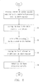
- FIG. 4 shows the flow chart of an LED driving method according to the embodiment of the present invention.
- step S1 a series of display signals outputted by the control-end processor 200 are stored in the shift register 310.
- step S2 the data stored in the shift register 310 is stored into the plurality of latches 320.
- step S3 the plurality of LEDs 400 are driven according to the data stored in the plurality of latches 320.
- step S4 the fault information of the plurality of LEDs 400 is stored into the shift register 310.
- the LED driver circuit 300 serially outputs the comparison results.
- FIG. 5 shows the waveforms of the input and output signals of the LED driver circuit 300.
- the clock signal controls the input operation of the shift register 310.
- the display signals are serially stored into the shift register 310.
- a pulse of the latch signal triggers the data stored in the shift register 310 to be stored into the plurality of latches 320.
- the switch signal then switches to low to activate the plurality of driver units 330, and the plurality of LEDs 400 are driven thereby according to the data stored in the plurality of latches 320.
- the fault information of the plurality of comparators 340 is stored into the shift register 310 before the next clock signal pulse arrives.
- the output signal is the comparison results, i.e., the fault information.
- the LED driver circuit 300 receives the display signals and drives the plurality of LEDs 400, the fault information of the plurality of LEDs 400 is outputted in real time. Therefore, the plurality of state registers 150 of the conventional LED driver circuit 100 are not required in the LED driver circuit 300.
- the control-end processor 200 compares the received fault information to the corresponding display signals to obtain the fault status of the plurality of LEDs 400. If the display signals are inconsistent with the corresponding fault information, the corresponding LEDs are determined to have been stuck open or short.
- the LED driving method and the circuit thereof according to embodiments of the present invention combine the fault detection mechanism with the display mode, and therefore the hardware costs can be reduced.
- the fault information can be transmitted back to the control device in real time, and hence the fault status of the faulty LEDs can be discovered sooner.
- the LED driving method and the circuit thereof according to embodiments of the present invention are capable of driving of the plurality of LEDs and detecting stuck open and/or stuck short at the same time. Therefore, the control device does not need to switch between different modes, and hence the control complexity is reduced.
Landscapes
- Engineering & Computer Science (AREA)
- Physics & Mathematics (AREA)
- Computer Hardware Design (AREA)
- General Physics & Mathematics (AREA)
- Theoretical Computer Science (AREA)
- Control Of El Displays (AREA)
- Control Of Indicators Other Than Cathode Ray Tubes (AREA)
Abstract
Description
- The present invention relates to a driver circuit and the method thereof, and more particularly, to an LED driver circuit and the method thereof.
- Compared to most conventional light emitting devices, LEDs consume less power, have longer lifetime and are more durable. Therefore, most indicator devices nowadays, such as traffic signs and commercial billboards, are implemented by LEDs. However, since a large number of those large indicator devices are placed outdoors, there are various sources of hazard, such as weather, animals colliding with them, or even droppings, that can damage such LED indicator devices. Unfortunately, conventional LED indicator devices seldom exhibit fault detection mechanism. Therefore, when LED indicator device are damaged, the control device, such as a control-end processor, has no knowledge of the location and the number of the damaged LEDs, and only by human eyes can such information be observed. Since the height of many modern LED indicator devices are over tens of meters, it requires maintenance personnel to climb up high to confirm information on the damaged LED indicator device, which is an arduous task and costs a lot of money.
- To solve the problems mentioned above, a fault detection mechanism can be designed for those LED indicator devices such that a control device is able to obtain the fault information of the damaged LEDs automatically.
FIG. 1 shows a conventionalLED driver circuit 100, which is connected to a control-end processor 200 and serves as the driver for a plurality ofLEDs 400. TheLED driver circuit 100 comprises ashift register 110, a plurality oflatches 120, a plurality ofdriver units 130, a plurality ofcomparators 140, a plurality ofstate registers 150 and astate switching circuit 160, wherein the number of the flip-flops in theshift register 110, the number of the plurality oflatches 120, the number of the plurality ofdriver units 130 and the number of the plurality ofLEDs 400 are the same. The input signals of theLED driver circuit 100 include an input data, a latch signal, a switch signal and a clock signal. The output signal of theLED driver circuit 100 includes an output data. The input terminal of theLED driver circuit 100 for the input data is connected to the first flip-flop of theshift register 110. The output terminal of theLED driver circuit 100 for the output data is connected to the last flip-flop of theshift register 110. - The
state switching circuit 160 determines the status of theLED driver circuit 100 according to the latch signal and the switch signal. When in a display mode, theLED driver circuit 100 receives display signals from the control-end processor 200. The received display signals are then serially stored in theshift register 110. When the storing process of the display signals is completed, the data stored in theshift register 110 is then outputted to and stored in the plurality oflatches 120. The output terminals of the plurality oflatches 120 are connected to the plurality ofdriver units 130 respectively. The plurality ofdriver units 130 have their output terminals connected to, and accordingly drive, the plurality ofLEDs 400. - When in a debug mode, the
LED driver circuit 100 receives fault-detecting signals (such as the signals of which the bits are all Os or all 1s) from the control-end processor 200. The received fault-detecting signals are then serially stored in theshift register 110. When the storing process of the fault-detecting signals is complete, the data stored in theshift register 110 is then outputted to and stored in the plurality oflatches 120 so as to be the input signal for the plurality ofdriver units 130. The input terminals of the plurality ofcomparators 140 are respectively connected to the output terminals of the plurality ofLEDs 400 and a reference voltage. The output signals of thecomparators 140 indicate whether the plurality ofLEDs 400 are in fault state. The plurality of state registers 150 store the comparison results of the plurality ofcomparators 140, and then stores such results to theshift register 110 at a later time such that the results can be outputted and transmitted back to the control-end processor 200. The control-end processor 200 obtains the fault information of the plurality ofLEDs 400 according to the comparison results. For instance, if the fault-detecting signal is a signal of which the bits are all 1s, which should turn on all the plurality ofLEDs 400, and the comparison results contain bits of "0", then the control-end processor 200 determines that theLEDs 400 at the corresponding locations are faulty. -
FIG. 2 shows the waveforms of the input and output signals of theLED driver circuit 100. As shown inFIG. 2 , the clock signal controls the input operation of theshift register 110. When in the display mode, the display signals are serially stored into theshift register 110. At such point, the output signals of theLED driver circuit 100 are redundant data. When the storing process of the display signals is complete, a pulse of the latch signal triggers the data stored in theshift register 110 to be stored into the plurality oflatches 120. The switch signal then switches to low to activate the plurality ofdriver units 130, and the plurality ofLEDs 400 are driven thereby according to the data stored in the plurality oflatches 120. At such point, the output signal is the display signals. After thestate switching circuit 160 switches the mode of theLED driver circuit 100 to the debug mode, thedriver circuit 100 is ready for the fault detection of the plurality of LEDs, or is ready to transmit the data stored in the plurality ofstate registers 150 back to the control-end processor 200. At such point, the output signal is the fault information. As shown inFIG. 2 , the modes of thedriver circuit 100 further include an exit mode, which serves as an interfacing mode between the display mode and the debug mode. - However, the aforesaid prior art needs to be switched between several modes, which heavily increases the control complexity for the control-
end processor 200. Moreover, the addition of the plurality ofstate registers 150 and thestate switching circuit 160 increases the hardware cost. Therefore, there is a need to design a display mechanism, which not only can detect the fault status of the plurality of LEDs synchronously, but also does not increase the hardware cost. - The method for driving a module including a plurality of LEDs according to one embodiment of the present invention comprises the steps of: driving the plurality of LEDs according to a series of display signals; synchronously detecting the plurality of LEDs in a display mode for obtaining fault information; and serially outputting the fault information.
- The LED driving method according to another embodiment of the present invention comprises the steps of: serially inputting a series of display signals to a shift register; storing the data stored in the shift register to a plurality of latches; driving a plurality of LEDs according to the data stored in the plurality of latches; synchronously storing fault information of LEDs to the shift register when the plurality of LEDs display the data stored in the plurality of latches; and serially outputting the fault information to determine the fault status of the plurality of LEDs.
- The LED driver circuit according to another embodiment of the present invention comprises a shift register, a plurality of latches, a plurality of driver units and a plurality of fault-detecting units. The shift register receives display signals from a control-end processor and transmits fault information to the control-end processor. The plurality of latches secure the output signals from the shift register. The plurality of driver units receive the data stored in the plurality of latches and drive a module comprising a plurality of LEDs. The plurality of fault-detecting units synchronously detect the plurality of LEDs in a display mode for obtaining fault information and store the fault information into the shift register.
- The objectives and advantages of the present invention will become apparent upon reading the following description and upon referring to the accompanying drawings of which:
-
FIG. 1 shows a conventional LED driver circuit; -
FIG. 2 shows waveforms of the input and output signals of the LED driver circuit according to one embodiment of the present invention; -
FIG. 3 shows an LED driving method and the circuit thereof according to one embodiment of the present invention; -
FIG. 4 shows the flow chart of an LED driving method according to the embodiment of the present invention; and -
FIG. 5 shows waveforms of the input and output signals of the LED driver circuit according to one embodiment of the present invention. -
FIG. 3 shows an LED driving method and the circuit thereof according to one embodiment of the present invention. TheLED driver circuit 300 is connected to the control-end processor 200, and serves as the driver for the plurality ofLEDs 400. TheLED driver circuit 300 comprises ashift register 310, a plurality oflatches 320, a plurality ofdriver units 330 and a plurality of fault-detectingunits 340, such as comparators, wherein the number of the flip-flops in theshift register 310, the number of the plurality oflatches 320, the number of the plurality ofdriver units 330, the number of the fault-detectingunits 340 and the number of the plurality ofLEDs 400 are the same. The input signals of theLED driver circuit 300 include an input data, a latch signal, a switch signal and a clock signal. The output signal of theLED driver circuit 300 includes an output data. The input terminal of theLED driver circuit 300 for the input data is connected to the first flip-flop of theshift register 310. The output terminal of theLED driver circuit 300 for the output data is connected to the last flip-flop of theshift register 310. - The LED driving method according to the embodiment of the present invention comprises only one mode, i.e., the display mode. Therefore, the
state switching circuit 160 in the conventionalLED driver circuit 100 is not required. When in the display mode, theLED driver circuit 300 receives the display signals from the control-end processor 200. The received display signals are then serially stored in theshift register 310. When the storing process of the display signals is completed, the data stored in theshift register 310 is then outputted to and stored in the plurality oflatches 320. The output terminals of the plurality oflatches 320 are connected to the plurality ofdriver units 330, respectively. The plurality ofdriver units 330 have their output terminals connected to, and accordingly drive, the plurality ofLEDs 400. The input terminals of the plurality ofcomparators 340 are respectively connected to the output terminals of the plurality ofLEDs 400 and a reference voltage. The output signals of thecomparators 340 indicate whether the plurality ofLEDs 400 are in fault state. The plurality ofcomparators 340 can detect two kinds of fault states of the plurality ofLEDs 400, i.e., whether the plurality ofLEDs 400 are stuck short or stuck open. For instance, if the display signals stored in the plurality oflatches 320 contain a bit of "1", and the corresponding bit of the output signals of the plurality ofcomparators 340 is "0"', then thecorresponding LED 400 is stuck open. If the display signals stored in the plurality oflatches 320 contain a bit of "0", and the corresponding bit of the output signals of the plurality ofcomparators 340 is "1", then thecorresponding LED 400 is stuck short. After the plurality ofLEDs 400 are driven and activated, the plurality ofcomparators 340 store the comparison results into theshift register 310 before the next clock signal pulse arrives. The comparison results are then outputted serially from the output terminal of theLED driver circuit 300. That is, the LED driving method according to the embodiment of the present invention combines fault detection mechanism with the display mode such that the fault information of being stuck short and open is transmitted back to the control-end processor 200 in real time. -
FIG. 4 shows the flow chart of an LED driving method according to the embodiment of the present invention. In step S1, a series of display signals outputted by the control-end processor 200 are stored in theshift register 310. In step S2, the data stored in theshift register 310 is stored into the plurality oflatches 320. In step S3, the plurality ofLEDs 400 are driven according to the data stored in the plurality oflatches 320. In step S4, the fault information of the plurality ofLEDs 400 is stored into theshift register 310. In step S5, theLED driver circuit 300 serially outputs the comparison results. -
FIG. 5 shows the waveforms of the input and output signals of theLED driver circuit 300. As shown inFIG. 5 , the clock signal controls the input operation of theshift register 310. When in display mode, the display signals are serially stored into theshift register 310. When the storing process of the display signals is completed, a pulse of the latch signal triggers the data stored in theshift register 310 to be stored into the plurality oflatches 320. The switch signal then switches to low to activate the plurality ofdriver units 330, and the plurality ofLEDs 400 are driven thereby according to the data stored in the plurality oflatches 320. The fault information of the plurality ofcomparators 340 is stored into theshift register 310 before the next clock signal pulse arrives. At such point, the output signal is the comparison results, i.e., the fault information. As shown in the preceding paragraph, after theLED driver circuit 300 receives the display signals and drives the plurality ofLEDs 400, the fault information of the plurality ofLEDs 400 is outputted in real time. Therefore, the plurality of state registers 150 of the conventionalLED driver circuit 100 are not required in theLED driver circuit 300. - The control-
end processor 200 compares the received fault information to the corresponding display signals to obtain the fault status of the plurality ofLEDs 400. If the display signals are inconsistent with the corresponding fault information, the corresponding LEDs are determined to have been stuck open or short. - In conclusion, the LED driving method and the circuit thereof according to embodiments of the present invention combine the fault detection mechanism with the display mode, and therefore the hardware costs can be reduced. On the other hand, the fault information can be transmitted back to the control device in real time, and hence the fault status of the faulty LEDs can be discovered sooner. In addition, the LED driving method and the circuit thereof according to embodiments of the present invention are capable of driving of the plurality of LEDs and detecting stuck open and/or stuck short at the same time. Therefore, the control device does not need to switch between different modes, and hence the control complexity is reduced.
- The above-described embodiments of the present invention are intended to be illustrative only. Those skilled in the art may devise numerous alternative embodiments without departing from the scope of the following claims.
Claims (15)
- A method for driving a module including a plurality of light emitting diodes (LEDs), comprising the steps of:driving the plurality of LEDs according to a series of display signals;synchronously detecting the plurality of LEDs in a display mode for obtaining fault information; andserially outputting the fault information.
- The method of Claim 1, wherein the display signals are not predetermined fault-detecting signals.
- The method of Claim 1, wherein the fault information is detected by comparing output currents of the plurality of LEDs to a reference current.
- The method of Claim 1, further comprising the step of comparing the fault information to the display signals by a control-end processor, wherein the processor outputs the display signals.
- An LED driving method comprising the steps of:serially inputting a series of display signals to a shift register;storing data in the shift register to a plurality of latches;driving a plurality of LEDs according to the data in the plurality of latches;synchronously storing fault information of LEDs to the shift register when the plurality of LEDs displays the data stored in the plurality of latches; andserially outputting the fault information to determine a fault status of the plurality of LEDs.
- The LED driving method of Claim 5, wherein the display signals are not predetermined fault-detecting signals.
- The LED driving method of Claim 5, wherein the input and output operations of the shift register are controlled by a clock signal.
- The LED driving method of Claim 7, wherein after the driving step, the synchronously storing step is executed before the next pulse of the clock signal.
- The LED driving method of Claim 5, wherein the number of flips-flops in the shift register, the number of latches and the number of LEDs are the same.
- An LED driver circuit, comprising:a shift register configured to receive display signals from a control-end processor and to transmit fault information to the control-end processor;a plurality of latches configured to latch output signals from the shift register;a plurality of driver units configured to receive data stored in the plurality of latches and to drive a module comprising a plurality of LEDs; anda plurality of fault-detecting units configured to synchronously detect the plurality of LEDs in a display mode for obtaining fault information and to store the fault information into the shift register.
- The LED driver circuit of Claim 10, wherein the display signals are not predetermined fault-detecting signals.
- The LED driver circuit of Claim 10, wherein the fault information is detected by comparing output currents of the plurality of LEDs to a reference current, and/or wherein the fault information is stored in the shift register before the shift register receives the next display signals.
- The LED driver circuit of Claim 10, wherein the shift register outputs the fault information and receives the next display signals at the same time.
- The LED driver circuit of Claim 10, wherein the number of flips-flops in the shift register, the number of the latches and the number of the LEDs are the same.
- The LED driver circuit of Claim 10, wherein the number of the fault-detecting units is the same as the number of the LEDs, and/or
wherein the fault-detecting units are comparators.
Applications Claiming Priority (1)
| Application Number | Priority Date | Filing Date | Title |
|---|---|---|---|
| TW097128572A TWI404459B (en) | 2008-07-29 | 2008-07-29 | Led driver circuit and the method thereof |
Publications (2)
| Publication Number | Publication Date |
|---|---|
| EP2149870A2 true EP2149870A2 (en) | 2010-02-03 |
| EP2149870A3 EP2149870A3 (en) | 2011-03-09 |
Family
ID=41110779
Family Applications (1)
| Application Number | Title | Priority Date | Filing Date |
|---|---|---|---|
| EP09166565A Withdrawn EP2149870A3 (en) | 2008-07-29 | 2009-07-28 | LED driver circuit and the method thereof |
Country Status (3)
| Country | Link |
|---|---|
| US (1) | US8184071B2 (en) |
| EP (1) | EP2149870A3 (en) |
| TW (1) | TWI404459B (en) |
Cited By (1)
| Publication number | Priority date | Publication date | Assignee | Title |
|---|---|---|---|---|
| CN112562580A (en) * | 2020-12-18 | 2021-03-26 | 上海谦奕电子科技有限公司 | LED display screen control method and system |
Families Citing this family (6)
| Publication number | Priority date | Publication date | Assignee | Title |
|---|---|---|---|---|
| CN102136235A (en) * | 2011-03-17 | 2011-07-27 | 深圳市中庆微科技开发有限公司 | Intelligent debugging system for detecting LED (Light Emitting Diode) display screen on line |
| US9232587B2 (en) * | 2011-09-30 | 2016-01-05 | Advanced Analogic Technologies, Inc. | Low cost LED driver with integral dimming capability |
| US9288861B2 (en) | 2011-12-08 | 2016-03-15 | Advanced Analogic Technologies Incorporated | Serial lighting interface with embedded feedback |
| US8779696B2 (en) | 2011-10-24 | 2014-07-15 | Advanced Analogic Technologies, Inc. | Low cost LED driver with improved serial bus |
| US20180308403A1 (en) * | 2017-04-20 | 2018-10-25 | GE Lighting Solutions, LLC | Cloud-based remote diagnostics for smart signage |
| CN113470555A (en) * | 2021-07-15 | 2021-10-01 | 中科芯集成电路有限公司 | LED display driving chip open-circuit lamp bead detection method |
Citations (2)
| Publication number | Priority date | Publication date | Assignee | Title |
|---|---|---|---|---|
| US20050062685A1 (en) | 2003-06-09 | 2005-03-24 | Masashi Nogawa | Drive circuit and display system with said drive circuit |
| EP2012298A2 (en) | 2007-07-02 | 2009-01-07 | Silicon Touch Technology, Inc. | Method for detecting pixel status of flat panel display and display driver thereof |
Family Cites Families (3)
| Publication number | Priority date | Publication date | Assignee | Title |
|---|---|---|---|---|
| DE4437453A1 (en) * | 1994-10-19 | 1996-04-25 | Patent Treuhand Ges Fuer Elektrische Gluehlampen Mbh | Method for operating a discharge lamp and circuit arrangement for operating a discharge lamp |
| US20050264474A1 (en) * | 2000-08-07 | 2005-12-01 | Rast Rodger H | System and method of driving an array of optical elements |
| JP2005108473A (en) * | 2003-09-29 | 2005-04-21 | Hitachi Ltd | Discharge lamp lighting device |
-
2008
- 2008-07-29 TW TW097128572A patent/TWI404459B/en active
- 2008-12-16 US US12/335,797 patent/US8184071B2/en active Active
-
2009
- 2009-07-28 EP EP09166565A patent/EP2149870A3/en not_active Withdrawn
Patent Citations (2)
| Publication number | Priority date | Publication date | Assignee | Title |
|---|---|---|---|---|
| US20050062685A1 (en) | 2003-06-09 | 2005-03-24 | Masashi Nogawa | Drive circuit and display system with said drive circuit |
| EP2012298A2 (en) | 2007-07-02 | 2009-01-07 | Silicon Touch Technology, Inc. | Method for detecting pixel status of flat panel display and display driver thereof |
Cited By (1)
| Publication number | Priority date | Publication date | Assignee | Title |
|---|---|---|---|---|
| CN112562580A (en) * | 2020-12-18 | 2021-03-26 | 上海谦奕电子科技有限公司 | LED display screen control method and system |
Also Published As
| Publication number | Publication date |
|---|---|
| US20100026190A1 (en) | 2010-02-04 |
| US8184071B2 (en) | 2012-05-22 |
| TW201006310A (en) | 2010-02-01 |
| EP2149870A3 (en) | 2011-03-09 |
| TWI404459B (en) | 2013-08-01 |
Similar Documents
| Publication | Publication Date | Title |
|---|---|---|
| US8184071B2 (en) | LED driver circuit and the method thereof | |
| US5444390A (en) | Means and method for sequentially testing electrical components | |
| US20080086667A1 (en) | Chip testing device and system | |
| EP1580720A2 (en) | Self light emitting display module, electronic equipment into which the same module is loaded, and inspection method of defect state in the same module | |
| US20070027981A1 (en) | Computer diagnostic system | |
| US11275108B2 (en) | Display device and testing method for display panel | |
| CN103747031A (en) | LED display screen fault network monitor system | |
| CN103309791A (en) | Display device with fault diagnosis function | |
| KR20030011189A (en) | Electric bulletin board having a inspection function and error detection method | |
| CN102118904B (en) | LED illuminating system and control method thereof | |
| US11348540B2 (en) | Display device driving method, and display device | |
| CN112654119B (en) | LED drive test method, driver, system and electronic equipment | |
| EP2012298A2 (en) | Method for detecting pixel status of flat panel display and display driver thereof | |
| US20090040198A1 (en) | Method for detecting pixel status of flat panel display and display driver thereof | |
| EP2204951A2 (en) | Serial transmission apparatus and the method thereof | |
| CN102760410A (en) | Scanning driving device and driving signal generating method thereof | |
| CN102339582A (en) | Indicator light control device | |
| US9913355B2 (en) | Method of forming a sequencing system and structure therefor | |
| CN101577086B (en) | Automatic addressing method of series circuit and automatic detection method of series quantity | |
| CN110660346A (en) | Micro LED display panel and detection method thereof | |
| US20210158771A1 (en) | Driving circuit, display module, and mobile body | |
| KR100220104B1 (en) | System or method for electric sign examination | |
| KR20110130785A (en) | Led apparatus for effective error detection and providing method thereof | |
| JP2005024821A (en) | Driving circuit of display device | |
| JP2742760B2 (en) | Information display device |
Legal Events
| Date | Code | Title | Description |
|---|---|---|---|
| PUAI | Public reference made under article 153(3) epc to a published international application that has entered the european phase |
Free format text: ORIGINAL CODE: 0009012 |
|
| AK | Designated contracting states |
Kind code of ref document: A2 Designated state(s): AT BE BG CH CY CZ DE DK EE ES FI FR GB GR HR HU IE IS IT LI LT LU LV MC MK MT NL NO PL PT RO SE SI SK SM TR |
|
| AX | Request for extension of the european patent |
Extension state: AL BA RS |
|
| PUAL | Search report despatched |
Free format text: ORIGINAL CODE: 0009013 |
|
| AK | Designated contracting states |
Kind code of ref document: A3 Designated state(s): AT BE BG CH CY CZ DE DK EE ES FI FR GB GR HR HU IE IS IT LI LT LU LV MC MK MT NL NO PL PT RO SE SI SK SM TR |
|
| AX | Request for extension of the european patent |
Extension state: AL BA RS |
|
| RIC1 | Information provided on ipc code assigned before grant |
Ipc: G09G 3/32 20060101ALI20110128BHEP Ipc: G09G 3/14 20060101ALI20110128BHEP Ipc: G09G 3/00 20060101AFI20110128BHEP |
|
| 17P | Request for examination filed |
Effective date: 20110905 |
|
| 17Q | First examination report despatched |
Effective date: 20120411 |
|
| STAA | Information on the status of an ep patent application or granted ep patent |
Free format text: STATUS: THE APPLICATION IS DEEMED TO BE WITHDRAWN |
|
| 18D | Application deemed to be withdrawn |
Effective date: 20140201 |