EP2149775A2 - Profile measuring instrument and profile measuring method - Google Patents
Profile measuring instrument and profile measuring method Download PDFInfo
- Publication number
- EP2149775A2 EP2149775A2 EP09166787A EP09166787A EP2149775A2 EP 2149775 A2 EP2149775 A2 EP 2149775A2 EP 09166787 A EP09166787 A EP 09166787A EP 09166787 A EP09166787 A EP 09166787A EP 2149775 A2 EP2149775 A2 EP 2149775A2
- Authority
- EP
- European Patent Office
- Prior art keywords
- workpiece
- coordinate system
- reference gauge
- measuring
- radius
- Prior art date
- Legal status (The legal status is an assumption and is not a legal conclusion. Google has not performed a legal analysis and makes no representation as to the accuracy of the status listed.)
- Granted
Links
- 238000000034 method Methods 0.000 title claims description 14
- 238000005259 measurement Methods 0.000 claims abstract description 81
- 238000012937 correction Methods 0.000 claims abstract description 61
- 230000001131 transforming effect Effects 0.000 claims abstract description 23
- 239000000523 sample Substances 0.000 claims description 20
- 230000007246 mechanism Effects 0.000 description 17
- 230000009466 transformation Effects 0.000 description 7
- 238000006073 displacement reaction Methods 0.000 description 5
- 230000008569 process Effects 0.000 description 5
- 238000010586 diagram Methods 0.000 description 4
- 239000011159 matrix material Substances 0.000 description 4
- 238000013519 translation Methods 0.000 description 4
- 241001422033 Thestylus Species 0.000 description 2
- 230000004048 modification Effects 0.000 description 2
- 238000012986 modification Methods 0.000 description 2
- 238000012545 processing Methods 0.000 description 2
- 238000005070 sampling Methods 0.000 description 2
Images



Classifications
-
- G—PHYSICS
- G01—MEASURING; TESTING
- G01B—MEASURING LENGTH, THICKNESS OR SIMILAR LINEAR DIMENSIONS; MEASURING ANGLES; MEASURING AREAS; MEASURING IRREGULARITIES OF SURFACES OR CONTOURS
- G01B21/00—Measuring arrangements or details thereof, where the measuring technique is not covered by the other groups of this subclass, unspecified or not relevant
- G01B21/02—Measuring arrangements or details thereof, where the measuring technique is not covered by the other groups of this subclass, unspecified or not relevant for measuring length, width, or thickness
- G01B21/04—Measuring arrangements or details thereof, where the measuring technique is not covered by the other groups of this subclass, unspecified or not relevant for measuring length, width, or thickness by measuring coordinates of points
- G01B21/045—Correction of measurements
-
- G—PHYSICS
- G01—MEASURING; TESTING
- G01B—MEASURING LENGTH, THICKNESS OR SIMILAR LINEAR DIMENSIONS; MEASURING ANGLES; MEASURING AREAS; MEASURING IRREGULARITIES OF SURFACES OR CONTOURS
- G01B5/00—Measuring arrangements characterised by the use of mechanical techniques
- G01B5/20—Measuring arrangements characterised by the use of mechanical techniques for measuring contours or curvatures
Definitions
- the present invention relates to a profile measuring instrument and a profile measuring method for measuring a profile of a workpiece by rotating the workpiece.
- a typically known profile measuring instrument includes a probe for measuring a workpiece and a rotary table to which the workpiece is fixed and which rotates the workpiece relative to the probe so as to measure a profile of the workpiece by rotating the workpiece (for example, Document 1; JP-A-2001-264048 ).
- a coordinate measuring machine measures a profile of a workpiece using a plurality of Cartesian coordinate systems such as a workpiece coordinate system (object coordinate system) set for the workpiece and a table coordinate system set for a rotary table.
- the coordinate systems can be mutually transformed by translation or rotation.
- a center position of a reference ball is measured at three or more rotational positions for every predetermined rotating angle while a rotary table, on the upper surface of which the reference ball is fixed, is rotated, so that the table coordinate system is set to have its origin at a center of a circle determined by the measured center position.
- One axial direction in the table coordinate system is defined as a normal direction of the circle determined by the measured center position of the reference ball, and other two axial directions are orthogonal to the normal direction.
- the workpiece coordinate system is set by measuring a workpiece. For example, one axial direction in the workpiece coordinate system is defined as an axial direction of the workpiece, and other two axial directions are orthogonal to the axial direction of the workpiece.
- measurement errors are caused by the runout of the rotary table, the squareness of the profile measuring instrument and the like because the coordinate systems are set at predetermined positions. Further, since the measurement errors are caused by the runout of the rotary table and the squareness of the profile measuring instrument, the measurement errors are increased as a measurement value is spaced apart from the origin of the table coordinate system (i.e., as a measurement position is spaced apart from the upper surface of the rotary table).
- An object of the invention is to provide a profile measuring instrument and a profile measuring method of properly correcting measurement errors caused by runout of a rotary table, squareness of the profile measuring instrument and the like to improve measurement accuracy.
- a profile measuring instrument for measuring a profile of a workpiece by rotating the workpiece includes: a probe that measures the workpiece; a rotary table to which the workpiece is fixed and which rotates the workpiece relative to the probe; a reference gauge measuring part that measures a diameter or radius of a reference gauge along an axial direction in a reference gauge coordinate system set for the reference gauge while the reference gauge is fixed to the rotary table, the reference gauge having a columnar shape or cylindrical shape and having a known diameter or radius; a correction function generating part that generates a correction function based on a difference between the diameter or radius measured by the reference gauge measuring part and the known diameter or radius and a measuring point of the reference gauge measuring part; a measuring part that measures the workpiece in a workpiece coordinate system set for the workpiece while the workpiece is fixed to the rotary table; a first transformer that transforms a measurement value measured by the measuring part in the workpiece coordinate system into the reference gauge coordinate system; a corrector that corrects by the correction function the
- the measured diameter or radius of the reference gauge includes a measurement error caused by the runout of the rotary table and the squareness of the profile measuring instrument. Accordingly, the difference between the diameter or radius of the reference gauge measured by the reference gauge measuring part at a predetermined measuring point and the known diameter or radius of the reference gauge at the predetermined measuring point is coincident with the measurement error caused by the runout of the rotary table and the squareness of the profile measuring instrument.
- the reference gauge may have any diameter or radius as long as it is given in advance. Since the profile measuring instrument outputs as a measurement value a position of the probe that is adjacent to or in contact with the surface of the workpiece, the measurement error caused by the runout of the rotary table and the squareness of the profile measuring instrument is constant even when the diameter or radius of the reference gauge is varied.
- the correction function can be generated in which the difference between the diameter or radius measured by the reference gauge measuring part and the known diameter or radius of the reference gauge is taken as the measurement error at the measuring point of the reference gauge measuring part.
- the correction function generated by the correction function generating part to the measurement value, the measurement error caused by the runout of the rotary table, the squareness of the profile measuring instrument and the like can be properly corrected, thereby improving measurement accuracy.
- the correction function is generated as a function of the measurement error at the measuring point in the reference gauge coordinate system, and the measurement value is measured at the measuring point by the measuring part in the workpiece coordinate system.
- the profile measuring instrument includes the first transformer and corrector according to the aspect of the invention
- the measurement value measured by the measuring part in the workpiece coordinate system can be transformed into the reference gauge coordinate system by the first transformer and then the measurement value transformed into the reference gauge coordinate system can be corrected by the correction function.
- the measuring point in the reference gauge coordinate system can be equivalent to the measuring point in the workpiece coordinate system and thus the correction function generated in the reference gauge coordinate system can be applied to the measurement value measured in the workpiece coordinate system.
- the profile measuring instrument includes the second transformer that transforms the measurement value corrected by the corrector in the reference gauge coordinate system into the workpiece coordinate system, the measurement value corrected by the corrector can be output as the measurement value in the workpiece coordinate system.
- a profile measuring method is used in a profile measuring instrument for measuring a profile of a workpiece by rotating the workpiece, the profile measuring instrument including: a probe that measures the workpiece; and a rotary table to which the workpiece is fixed and which rotates the workpiece relative to the probe.
- the profile measuring method includes: measuring a diameter or radius of a reference gauge along an axial direction in a reference gauge coordinate system set for the reference gauge while the reference gauge is fixed to the rotary table, the reference gauge having a columnar shape or cylindrical shape and having a known diameter or radius; generating a correction function based on a difference between the diameter or radius measured in the measuring of the reference gauge and the known diameter or radius and a measuring point in the measuring of the reference gauge; measuring the workpiece in a workpiece coordinate system set for the workpiece while the workpiece is fixed to the rotary table; first transforming a measurement value measured in the measuring of the workpiece in the workpiece coordinate system into the reference gauge coordinate system; correcting by the correction function the measurement value transformed into the reference gauge coordinate system in the first transforming; and second transforming the measurement value corrected in the reference gauge coordinate system in the correcting into the workpiece coordinate system.
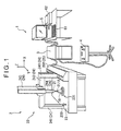
- Fig. 1 is an overall diagram schematically showing a coordinate measuring machine I according to an exemplary embodiment of the invention.
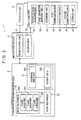
- Fig. 2 is a block diagram showing an outline arrangement of the coordinate measuring machine 1.
- the upward direction is referred to as a +Z-axis direction, and two axes orthogonal to the Z-axis are referred to as an X-axis and a Y-axis. The same applies to the other attached drawings.
- the coordinate measuring machine 1 serving as a profile measuring instrument includes: a coordinate measuring machine body 2; a motion controller 3 for controlling the drive of the coordinate measuring machine body 2; an operation unit 4 for outputting a command to the motion controller 3 via an operation lever to manually manipulate the coordinate measuring machine body 2; a host computer 5 for outputting a predetermined command to the motion controller 3 and executing arithmetic processing such as profile analysis of a workpiece 10 disposed on the coordinate measuring machine body 2; and an input unit 61 and an output unit 62 that are connected to the host computer 5.
- the input unit 61 inputs to the host computer 5 measuring conditions and the like in the coordinate measuring machine 1.
- the output unit 62 outputs results of the measurement by the coordinate measuring machine 1.
- the coordinate measuring machine body 2 includes a stylus 211A to be brought into contact with a surface of the workpiece 10 on a distal end (in the -Z-axis direction).
- the coordinate measuring machine body 2 further includes a probe 21 for measuring the workpiece 10, a movement mechanism 22 for holding a base end (in the +Z-axis direction) of the probe 21 and moving the probe 21, and a base 23 on which the movement mechanism 22 stands upright.
- the movement mechanism 22 includes a slide mechanism 24 for holding the base end of the probe 21 and causing the probe 21 to slide, and a drive mechanism 25 for driving the slide mechanism 24 to move the probe 21.
- the slide mechanism 24 includes: two beam support bodies 241 extending in the +Z-axis direction from both sides of the base 23 in the X-axis direction and slidable in the Y-axis direction; a beam 242 supported by the beam support bodies 241 and extending in the X-axis direction; a column 243 having a cylindrical shape extending in the Z-axis direction and slidable on the beam 242 in the X-axis direction; and a spindle 244 inserted to the inside of the column 243 and slidable within the column 243 in the Z-axis direction.
- the drive mechanism 25 includes: a Y-axis drive unit 25Y that supports one of the beam support bodies 241 located in +X-axis direction and slides the one of the beam support bodies 241 in the Y-axis direction; an X-axis drive unit 25X (not shown in Fig. 1 ) that slides the column 243 on the beam 242 in the X-axis direction; and a Z-axis drive unit 25Z (not shown in Fig. 1 ) that slides the spindle 244 within the column 243 in the Z-axis direction.
- the drive mechanism 25 includes sensors for detecting a displacement of the slide mechanism 24 in the respective axis directions. Each of the sensors outputs a pulse signal in accordance with the displacement of the slide mechanism 24.
- the base 23 includes: a rotary table 231 which is provided substantially in the center of the upper surface of the base 23 and to which the workpiece 10 is fixed; and a rotation drive unit 232 (not shown in Fig. 1 ) for rotating the rotary table 231 about the Z-axis on the upper surface of the base 23. Accordingly, the rotary table 231 rotates the workpiece 10 relative to the probe 21.
- the rotation drive unit 232 includes a sensor for detecting a rotational amount of the rotary table 231 and outputting a pulse signal in accordance with the rotational amount of the rotary table 231.
- a reference ball 233 of which a radius is known is disposed on the base 23 for calibration of the coordinate measuring machine body 2.
- the reference ball 233 may be disposed on a plurality of positions on the base 23.
- Fig. 3 shows a cylindrical square 101 fixed to the rotary table 231.
- Fig. 4 shows a ball screw 102 fixed to the rotary table 231.
- the rotary table 231 includes a disk-shaped chuck 234 attached to the upper surface thereof.
- the chuck 234 includes three jaws 234A disposed on the outer circumference at equal intervals.
- the jaws 234A press the workpiece 10 inwardly, so that the chuck 234 holds the workpiece 10 (the cylindrical square 101, the ball screw 102). Accordingly, the workpiece 10 is fixed to the rotary table 231.
- the cylindrical square 101 is held by the jaws 234A of the chuck 234 so that the central axis of the cylindrical square 101 is substantially coincident with the rotational axis of the rotary table 231 (the dashed-dotted line in Fig. 3 ) while the lower surface of the cylindrical square 101 contacts the upper surface of the chuck 234.
- the ball screw 102 is inserted into a hole (not shown) provided in the center of the chuck 234 and is held by the jaws 234A of the chuck 234 so that the central axis of the ball screw 102 is substantially coincident with the rotational axis of the rotary table 231 (the dashed-dotted line in Fig. 4 ).
- the motion controller 3 includes: a drive control unit 31 for controlling the drive mechanism 25 and rotation drive unit 232 in accordance with a command from the operation unit 4 or the host computer 5; and a counter unit 32 for counting pulse signals output from the sensors provided on the drive mechanism 25 and rotation drive unit 232.
- the counter unit 32 measures a displacement of the slide mechanism 24 and a rotational amount of the rotary table 231 by counting the pulse signals output from the sensors. Then, the displacement of the slide mechanism 24 and the rotational amount of the rotary table 231 measured by the counter unit 32 are output to the host computer 5.
- the host computer 5 is equipped with a CPU (Central Processing Unit).
- the host computer 5 controls the coordinate measuring machine body 2 by outputting a predetermined command to the motion controller 3 to rotate the workpiece 10 on the rotary table 231 in order to measure the profile of the workpiece 10.
- the host computer 5 includes a reference gauge measuring part 51, a correction function generating part 52, a measuring part 53, a first transforming part 54, a correcting part 55, a second transforming part 56 and a storage unit 57.
- the reference gauge measuring part 51 measures diameters of the cylindrical square 101 in the axis direction in a reference gauge coordinate system B (X B , Y B , Z B ) set for the cylindrical square 101 while the cylindrical square 101 is fixed to the rotary table 231.
- the diameters of the cylindrical square 101 serving as a reference gauge are measured in advance at a plurality of measuring points along the central axis by a coordinate measuring machine that is more accurate than the coordinate measuring machine 1 (hereinafter referred to as a standard machine).
- a coordinate measuring machine that is more accurate than the coordinate measuring machine 1 (hereinafter referred to as a standard machine).
- the diameters of the cylindrical square 101 are known.
- the height of the cylindrical square 101 is 300 mm.
- the diameters of the cylindrical square 101 are measured in advance by the standard machine at measuring points that are spaced apart by 10 mm interval within a range of a start point that is 10 mm high from the lower surface of the cylindrical square 101 to an end point that is 290 mm high from the lower surface.
- the standard machine is used, the measurement is done by moving a probe of the standard machine along the surface of the cylindrical square 101 without using the rotary table so as to avoid the influence of the runout of the rotary table.
- an axis passing through centers of two circles provided by surface profiles of the cylindrical square 101 measured at two different height positions along the central axis of the cylindrical square 101 is set as a Z B -axis.
- Two axes on the upper surface of the chuck 234, i.e., the lower surface of the cylindrical square 101, are set as an X B -axis and a Y B -axis. Note that the position of the upper surface of the chuck 234 is set by being measured by the coordinate measuring machine 1. Also, the X B -axis and Y B -axis are set to be orthogonal to the Z B -axis.
- the correction function generating part 52 generates a correction function based on: a difference between the diameter of the cylindrical square 101 measured by the reference gauge measuring part 51 and the known diameter, i.e., the diameter of the cylindrical square 101 measured by the standard machine; and the axial measuring point for measurement by the reference gauge measuring part 51.
- the measuring part 53 measures the ball screw 102 in a workpiece coordinate system W set for the ball screw 102 while the ball screw 102 is fixed to the rotary table 231.
- an axis passing through centers of two circles provided by surface profiles of the ball screw 102 measured at two different height positions along the central axis of the ball screw 102 is set as a Z W -axis, and two axes passing through the center of the lower circle (in -Z-axis direction) out of the two circles are set as an X W -axis and a Y W -axis respectively. Also, the X W -axis and Y W -axis are set to be orthogonal to the Z W -axis.
- the first transforming part 54 transforms a measurement value measured by the measuring part 53 in the workpiece coordinate system W into the reference gauge coordinate system B.
- the host computer 5 measures the profile of the workpiece using a plurality of Cartesian coordinate systems.
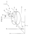
- Fig. 5 shows relationships among the plurality of Cartesian coordinate systems used in the host computer 5.
- the workpiece 10 is deviated from the center of the rotary table 231 to simplify the drawing.
- the host computer 5 measures the profile of the workpiece 10 using a plurality of coordinate systems including: a scale coordinate system S (X S , Y S , Z S ) set for the slide mechanism 24; a machine coordinate system M (X M , Y M , Z M ) set to have its origin at the center of the reference ball 233; a table coordinate system T (X T , Y T , Z T ) set for the rotary table 231; and a rotation coordinate system T ⁇ (not shown) provided when the table coordinate system T is rotated by a rotating angle ⁇ , in addition to the above-described reference gauge coordinate system B and workpiece coordinate system W.
- the coordinate measuring machine body 2 is controlled using the scale coordinate system S.
- the scale coordinate system S is set in advance as an absolute coordinate system for the coordinate measuring machine 1, and the machine coordinate system M is set by measuring a center position of the reference ball 233.
- a center position of a reference ball (not shown) having the same arrangement as the reference ball 233 is measured at three or more rotational positions for every predetermined rotating angle while the rotary table 231, on the upper surface of which the reference ball is fixed, is rotated. Then, the table coordinate system T is set to have its origin at a center of a circle determined by the measured center position.
- One axis (Z T -axis) direction in the table coordinate system T is defined as a normal direction of the circle determined by the measured center position of the reference ball, and other two axes (X T -axis and Y T -axis) directions are orthogonal to the normal direction.
- the reference gauge coordinate system B and workpiece coordinate system W are rotated with the rotation of the rotary table 231, i.e., the rotation of the rotation coordinate system T ⁇ .
- the coordinate systems can be mutually transformed by translation or rotation.
- a point P measured in the workpiece coordinate system W (see Fig. 5 ) can be transformed into the rotation coordinate system T ⁇ by translation of the coordinate system W using a translation matrix.
- the point P transformed into the rotation coordinate system T ⁇ can be further transformed into the table coordinate system T by rotation of the coordinate system T ⁇ using a rotation matrix.
- the first transforming part 54 transforms the measurement value measured in the workpiece coordinate system W into the scale coordinate system S through the rotation coordinate system T ⁇ , table coordinate system T and machine coordinate system M, and then into the reference gauge coordinate system B through the machine coordinate system M, table coordinate system T and rotation coordinate system T ⁇ .
- the correcting part 55 corrects the measurement value transformed into the reference gauge coordinate system B by the first transforming part 54 using a correction function generated by the correction function generating part 52.
- the second transforming part 56 transforms the measurement value corrected by the correcting part 55 in the reference gauge coordinate system B into the workpiece coordinate system W.
- the second transforming part 56 transforms the measurement value corrected in the reference gauge coordinate system B into the scale coordinate system S through the machine coordinate system M, table coordinate system T and rotation coordinate system T ⁇ , and then into the workpiece coordinate system W through the rotation coordinate system T ⁇ , table coordinate system T and machine coordinate system M.
- the storage unit 57 stores the measurement values measured by the reference gauge measuring part 51 and measuring part 53 and the correction function generated by the correction function generating part 52.
- the storage unit 57 also stores a program for executing a profile measuring process as described below.
- Fig. 6 is a flow chart showing a profile measuring process of the coordinate measuring machine 1.
- the host computer 5 executes steps S1 to S6 as described below when the profile measuring process is executed.
- the reference gauge measuring part 51 measures diameters of the cylindrical square 101 along the axis direction in the reference gauge coordinate system B (X B , Y B , Z B ) set for cylindrical square 101 while the cylindrical square 101 is fixed to the rotary table 231 (reference gauge measurement step S1).
- a measuring range of the reference gauge measuring part 51 is set in accordance with a measuring range of the ball screw 102.
- the reference gauge measuring part 51 measures the diameters of the cylindrical square 101 at measuring points spaced apart by 40 mm interval within a range of a start point that is 20 mm high from the upper surface of the chuck to an end point that is 220 mm high from the upper surface, i.e., within a range of the screw part 102A.
- the measuring range and the interval between the measuring points of the reference gauge measuring part 51 are settable in accordance with a measuring range of a workpiece to be measured and smoothness of a surface profile thereof.
- the correction function generating part 52 After the diameters of the cylindrical square 101 are measured in the reference gauge measurement step S1, the correction function generating part 52 generates a correction function based on: a difference between the diameter of the cylindrical square 101 measured by the reference gauge measuring part 51 and the known diameter; and the axial measuring point for measurement by the reference gauge measuring part 51 (correction function generation step S2).
- Fig. 7 shows the correction function generated by the correction function generating part 52.
- the horizontal axis represents an axial measuring point H (H1 to H6) when the measurement is done by the reference gauge measuring part 51
- the vertical axis represents a radius difference R (R1 to R6) calculated based on the difference between the diameter of the cylindrical square 101 measured by the reference gauge measuring part 51 and the known diameter.
- the correction function f generated by the correction function generating part 52 is stored in the storage unit 57.
- the correction function may be generated by other approximation such as spline approximation instead of the above-described polynomial approximation.
- the measuring part 53 measures the ball screw 102 in the workpiece coordinate system W set for the ball screw 102 while the ball screw 102 is fixed to the rotary table 231 as shown in Fig. 4 (measurement step S3),
- a measurement value (x w , y w , z w ) is obtained at a plurality of measuring points (positions of the stylus 211A) by sampling a displacement of the slide mechanism 24 and a rotational amount of the rotary table 231 measured by the counter unit 32 at a predetermined sampling interval while the stylus 211A contacts a screw groove of the ball screw 102 and the rotary table 231 is rotated.
- the measurement value measured by the measuring part 53 is stored in the storage unit 57.
- the first transforming part 54 transforms the measurement value measured by the measuring part 53 in the workpiece coordinate system W into the reference gauge coordinate system B (first transformation step S4).
- the measurement value (x B , y B , z B ) transformed into the reference gauge coordinate system B by the first transforming part 54 is corrected with the correction function f generated by the correction function generating part 52 (correction step S5).
- Fig. 8 shows a relationship between the measurement value transformed into the reference gauge coordinate system B and the measurement value corrected by the correcting part 55.
- the measurement value prior to the correction is expressed as (x B , y B ) and the measurement value after the correction is expressed as (x B ', y B ').
- the correcting part 55 corrects the measurement value transformed into the reference gauge coordinate system B based on the following formulae (1) to (4).
- z B indicating the measuring point H of the measurement value is assigned to the correction function f to calculate a radius difference R based on the formula (1).
- R f z B
- the corrected measurement value (x B ', y B ') is calculated.
- ⁇ indicates an angle between the X B -axis and the measurement value in the reference gauge coordinate system B.
- the second transforming part 56 transforms the measurement value (x B ', y B ', z B ) corrected by the correcting part 55 in the reference gauge coordinate system B into the workpiece coordinate system W (second transformation step S6),
- the coordinate measuring machine 1 corrects measurement errors caused by the runout of the rotary table 231, the squareness of the coordinate measuring machine 1 and the like. Then, the diameter of the ball screw 102 is calculated based on the corrected measurement value.
- the invention is not limited to the above-described exemplary embodiment, but includes any modifications, improvements and the like as long as a workpiece of the invention can be achieved.
- the reference gauge measuring part 51 measures the diameter of the cylindrical square 101
- the correction function generating part 52 generates the correction function based on the radius difference R calculated based on the difference between the diameter of the cylindrical square 101 measured by the reference gauge measuring part 51 and the known diameter and the axial measuring point H for measurement by the reference gauge measuring part 51.
- the reference gauge measuring part may measure a radius of a reference gauge
- the correction function generating part may generate a steric correction function based on a difference between the radius of the reference gauge measured by the reference gauge measuring part and a known radius, an axial measuring point for measurement by the reference gauge measuring part, and a rotating angle of a rotary table.
- the reference gauge measuring part measure a diameter or radius of a reference gauge along an axial direction in a reference gauge coordinate system set for the reference gauge and the correction function generating part generate a correction function based on a difference between the diameter or radius measured by the reference gauge measuring part and a known diameter or radius and a measuring point of the reference gauge measuring part.
- cylindrical square 101 is used as the reference gauge in the exemplary embodiment, other component may be used as the reference gauge as long as it has a columnar shape or cylindrical shape and has a known diameter or radius.
- the first transforming part 54 and second transforming part 56 transforms the reference gauge coordinate system B and workpiece coordinate system W through the rotation coordinate system T ⁇ , table coordinate system T and machine coordinate system M.
- a transformation matrix for directly transforming the reference gauge coordinate system B and workpiece coordinate system W may be generated and coordinate transformation may be performed by the generated transformation matrix.
- the profile measuring instrument is exemplified by the coordinate measuring machine 1 in the exemplary embodiment, the invention is applicable to other measuring instrument as long as it is a profile measuring instrument including a probe and a rotary table for measuring a profile of a workpiece by rotating the workpiece.
Landscapes
- Physics & Mathematics (AREA)
- General Physics & Mathematics (AREA)
- A Measuring Device Byusing Mechanical Method (AREA)
Abstract
Description
- The present invention relates to a profile measuring instrument and a profile measuring method for measuring a profile of a workpiece by rotating the workpiece.
- A typically known profile measuring instrument includes a probe for measuring a workpiece and a rotary table to which the workpiece is fixed and which rotates the workpiece relative to the probe so as to measure a profile of the workpiece by rotating the workpiece (for example,
Document 1;JP-A-2001-264048 - A coordinate measuring machine (profile measuring instrument) as disclosed in
Document 1 measures a profile of a workpiece using a plurality of Cartesian coordinate systems such as a workpiece coordinate system (object coordinate system) set for the workpiece and a table coordinate system set for a rotary table. The coordinate systems can be mutually transformed by translation or rotation. - Typically, in the table coordinate system, a center position of a reference ball is measured at three or more rotational positions for every predetermined rotating angle while a rotary table, on the upper surface of which the reference ball is fixed, is rotated, so that the table coordinate system is set to have its origin at a center of a circle determined by the measured center position. One axial direction in the table coordinate system is defined as a normal direction of the circle determined by the measured center position of the reference ball, and other two axial directions are orthogonal to the normal direction. The workpiece coordinate system is set by measuring a workpiece. For example, one axial direction in the workpiece coordinate system is defined as an axial direction of the workpiece, and other two axial directions are orthogonal to the axial direction of the workpiece.
- However, when the workpiece is measured using the workpiece coordinate system and table coordinate system that are set as described above, measurement errors are caused by the runout of the rotary table, the squareness of the profile measuring instrument and the like because the coordinate systems are set at predetermined positions. Further, since the measurement errors are caused by the runout of the rotary table and the squareness of the profile measuring instrument, the measurement errors are increased as a measurement value is spaced apart from the origin of the table coordinate system (i.e., as a measurement position is spaced apart from the upper surface of the rotary table).
- An object of the invention is to provide a profile measuring instrument and a profile measuring method of properly correcting measurement errors caused by runout of a rotary table, squareness of the profile measuring instrument and the like to improve measurement accuracy.
- According to an aspect of the invention, a profile measuring instrument for measuring a profile of a workpiece by rotating the workpiece includes: a probe that measures the workpiece; a rotary table to which the workpiece is fixed and which rotates the workpiece relative to the probe; a reference gauge measuring part that measures a diameter or radius of a reference gauge along an axial direction in a reference gauge coordinate system set for the reference gauge while the reference gauge is fixed to the rotary table, the reference gauge having a columnar shape or cylindrical shape and having a known diameter or radius; a correction function generating part that generates a correction function based on a difference between the diameter or radius measured by the reference gauge measuring part and the known diameter or radius and a measuring point of the reference gauge measuring part; a measuring part that measures the workpiece in a workpiece coordinate system set for the workpiece while the workpiece is fixed to the rotary table; a first transformer that transforms a measurement value measured by the measuring part in the workpiece coordinate system into the reference gauge coordinate system; a corrector that corrects by the correction function the measurement value transformed into the reference gauge coordinate system by the first transformer; and a second transformer that transforms the measurement value corrected by the corrector in the reference gauge coordinate system into the workpiece coordinate system.
- When the reference gauge of the known diameter or radius is measured by the reference gauge measuring part, the measured diameter or radius of the reference gauge includes a measurement error caused by the runout of the rotary table and the squareness of the profile measuring instrument. Accordingly, the difference between the diameter or radius of the reference gauge measured by the reference gauge measuring part at a predetermined measuring point and the known diameter or radius of the reference gauge at the predetermined measuring point is coincident with the measurement error caused by the runout of the rotary table and the squareness of the profile measuring instrument.
- The reference gauge may have any diameter or radius as long as it is given in advance. Since the profile measuring instrument outputs as a measurement value a position of the probe that is adjacent to or in contact with the surface of the workpiece, the measurement error caused by the runout of the rotary table and the squareness of the profile measuring instrument is constant even when the diameter or radius of the reference gauge is varied.
- Since the profile measuring instrument includes the reference gauge measuring part and correction function generating part according to the aspect of the invention, the correction function can be generated in which the difference between the diameter or radius measured by the reference gauge measuring part and the known diameter or radius of the reference gauge is taken as the measurement error at the measuring point of the reference gauge measuring part.
- Thus, by applying the correction function generated by the correction function generating part to the measurement value, the measurement error caused by the runout of the rotary table, the squareness of the profile measuring instrument and the like can be properly corrected, thereby improving measurement accuracy.
- The correction function is generated as a function of the measurement error at the measuring point in the reference gauge coordinate system, and the measurement value is measured at the measuring point by the measuring part in the workpiece coordinate system.
- Since the profile measuring instrument includes the first transformer and corrector according to the aspect of the invention, the measurement value measured by the measuring part in the workpiece coordinate system can be transformed into the reference gauge coordinate system by the first transformer and then the measurement value transformed into the reference gauge coordinate system can be corrected by the correction function. In other words, due to the coordinate transformation by the first transformer, the measuring point in the reference gauge coordinate system can be equivalent to the measuring point in the workpiece coordinate system and thus the correction function generated in the reference gauge coordinate system can be applied to the measurement value measured in the workpiece coordinate system.
- Further, since the profile measuring instrument includes the second transformer that transforms the measurement value corrected by the corrector in the reference gauge coordinate system into the workpiece coordinate system, the measurement value corrected by the corrector can be output as the measurement value in the workpiece coordinate system.
- According to another aspect of the invention, a profile measuring method is used in a profile measuring instrument for measuring a profile of a workpiece by rotating the workpiece, the profile measuring instrument including: a probe that measures the workpiece; and a rotary table to which the workpiece is fixed and which rotates the workpiece relative to the probe. The profile measuring method includes: measuring a diameter or radius of a reference gauge along an axial direction in a reference gauge coordinate system set for the reference gauge while the reference gauge is fixed to the rotary table, the reference gauge having a columnar shape or cylindrical shape and having a known diameter or radius; generating a correction function based on a difference between the diameter or radius measured in the measuring of the reference gauge and the known diameter or radius and a measuring point in the measuring of the reference gauge; measuring the workpiece in a workpiece coordinate system set for the workpiece while the workpiece is fixed to the rotary table; first transforming a measurement value measured in the measuring of the workpiece in the workpiece coordinate system into the reference gauge coordinate system; correcting by the correction function the measurement value transformed into the reference gauge coordinate system in the first transforming; and second transforming the measurement value corrected in the reference gauge coordinate system in the correcting into the workpiece coordinate system.
- According to the above-described profile measuring method, the same advantages can be attained as those of the above-described profile measuring instrument.
-
-
Fig. 1 is an overall diagram schematically showing a coordinate measuring machine according to an exemplary embodiment of the invention. -
Fig. 2 is a block diagram showing an outline arrangement of the coordinate measuring machine according to the exemplary embodiment. -
Fig. 3 shows a cylindrical square fixed to a rotary table according to the exemplary embodiment. -
Fig. 4 shows a ball screw fixed to the rotary table according to the exemplary embodiment. -
Fig. 5 shows relationships among a plurality of Cartesian coordinate systems used in a host computer according to the exemplary embodiment. -
Fig. 6 is a flow chart showing a profile measuring process of the coordinate measuring machine according to the exemplary embodiment. -
Fig. 7 shows a correction function generated by a correction function generating part according to the exemplary embodiment. -
Fig. 8 shows a relationship between a measurement value transformed into a reference gauge coordinate system and a measurement value corrected by a correcting part according to the exemplary embodiment. - Exemplary embodiment(s) of the invention will be described below with reference to the attached drawings.
-
Fig. 1 is an overall diagram schematically showing a coordinate measuring machine I according to an exemplary embodiment of the invention.Fig. 2 is a block diagram showing an outline arrangement of thecoordinate measuring machine 1. InFig. 1 , the upward direction is referred to as a +Z-axis direction, and two axes orthogonal to the Z-axis are referred to as an X-axis and a Y-axis. The same applies to the other attached drawings. - As shown in
Fig. 1 , thecoordinate measuring machine 1 serving as a profile measuring instrument includes: a coordinatemeasuring machine body 2; amotion controller 3 for controlling the drive of the coordinatemeasuring machine body 2; anoperation unit 4 for outputting a command to themotion controller 3 via an operation lever to manually manipulate the coordinatemeasuring machine body 2; ahost computer 5 for outputting a predetermined command to themotion controller 3 and executing arithmetic processing such as profile analysis of aworkpiece 10 disposed on the coordinatemeasuring machine body 2; and aninput unit 61 and anoutput unit 62 that are connected to thehost computer 5. Theinput unit 61 inputs to thehost computer 5 measuring conditions and the like in thecoordinate measuring machine 1. Theoutput unit 62 outputs results of the measurement by thecoordinate measuring machine 1. - The coordinate
measuring machine body 2 includes a stylus 211A to be brought into contact with a surface of theworkpiece 10 on a distal end (in the -Z-axis direction). The coordinatemeasuring machine body 2 further includes a probe 21 for measuring theworkpiece 10, amovement mechanism 22 for holding a base end (in the +Z-axis direction) of the probe 21 and moving the probe 21, and abase 23 on which themovement mechanism 22 stands upright. - The
movement mechanism 22 includes aslide mechanism 24 for holding the base end of the probe 21 and causing the probe 21 to slide, and adrive mechanism 25 for driving theslide mechanism 24 to move the probe 21. - The
slide mechanism 24 includes: twobeam support bodies 241 extending in the +Z-axis direction from both sides of thebase 23 in the X-axis direction and slidable in the Y-axis direction; abeam 242 supported by thebeam support bodies 241 and extending in the X-axis direction; acolumn 243 having a cylindrical shape extending in the Z-axis direction and slidable on thebeam 242 in the X-axis direction; and aspindle 244 inserted to the inside of thecolumn 243 and slidable within thecolumn 243 in the Z-axis direction. - As shown in
Figs. 1 and2 , thedrive mechanism 25 includes: a Y-axis drive unit 25Y that supports one of thebeam support bodies 241 located in +X-axis direction and slides the one of thebeam support bodies 241 in the Y-axis direction; anX-axis drive unit 25X (not shown inFig. 1 ) that slides thecolumn 243 on thebeam 242 in the X-axis direction; and a Z-axis drive unit 25Z (not shown inFig. 1 ) that slides thespindle 244 within thecolumn 243 in the Z-axis direction. Though not illustrated, thedrive mechanism 25 includes sensors for detecting a displacement of theslide mechanism 24 in the respective axis directions. Each of the sensors outputs a pulse signal in accordance with the displacement of theslide mechanism 24. - As shown in
Figs. 1 and2 , thebase 23 includes: a rotary table 231 which is provided substantially in the center of the upper surface of thebase 23 and to which theworkpiece 10 is fixed; and a rotation drive unit 232 (not shown inFig. 1 ) for rotating the rotary table 231 about the Z-axis on the upper surface of thebase 23. Accordingly, the rotary table 231 rotates theworkpiece 10 relative to the probe 21. Though not illustrated, therotation drive unit 232 includes a sensor for detecting a rotational amount of the rotary table 231 and outputting a pulse signal in accordance with the rotational amount of the rotary table 231. As shown inFig. 1 , areference ball 233 of which a radius is known is disposed on thebase 23 for calibration of the coordinatemeasuring machine body 2. Thereference ball 233 may be disposed on a plurality of positions on thebase 23. -
Fig. 3 shows acylindrical square 101 fixed to the rotary table 231.Fig. 4 shows aball screw 102 fixed to the rotary table 231. - As shown in
Figs. 3 and 4 , the rotary table 231 includes a disk-shaped chuck 234 attached to the upper surface thereof. Thechuck 234 includes threejaws 234A disposed on the outer circumference at equal intervals. Thejaws 234A press theworkpiece 10 inwardly, so that thechuck 234 holds the workpiece 10 (thecylindrical square 101, the ball screw 102). Accordingly, theworkpiece 10 is fixed to the rotary table 231. - As shown in
Fig. 3 , thecylindrical square 101 is held by thejaws 234A of thechuck 234 so that the central axis of thecylindrical square 101 is substantially coincident with the rotational axis of the rotary table 231 (the dashed-dotted line inFig. 3 ) while the lower surface of the cylindrical square 101 contacts the upper surface of thechuck 234. - As shown in
Fig. 4 , theball screw 102 is inserted into a hole (not shown) provided in the center of thechuck 234 and is held by thejaws 234A of thechuck 234 so that the central axis of theball screw 102 is substantially coincident with the rotational axis of the rotary table 231 (the dashed-dotted line inFig. 4 ). - As shown in
Fig. 2 , themotion controller 3 includes: adrive control unit 31 for controlling thedrive mechanism 25 androtation drive unit 232 in accordance with a command from theoperation unit 4 or thehost computer 5; and acounter unit 32 for counting pulse signals output from the sensors provided on thedrive mechanism 25 androtation drive unit 232. - The
counter unit 32 measures a displacement of theslide mechanism 24 and a rotational amount of the rotary table 231 by counting the pulse signals output from the sensors. Then, the displacement of theslide mechanism 24 and the rotational amount of the rotary table 231 measured by thecounter unit 32 are output to thehost computer 5. - The
host computer 5 is equipped with a CPU (Central Processing Unit). Thehost computer 5 controls the coordinate measuringmachine body 2 by outputting a predetermined command to themotion controller 3 to rotate theworkpiece 10 on the rotary table 231 in order to measure the profile of theworkpiece 10. As shown inFig. 2 , thehost computer 5 includes a referencegauge measuring part 51, a correctionfunction generating part 52, a measuringpart 53, a first transformingpart 54, a correctingpart 55, a second transformingpart 56 and astorage unit 57. - As shown in
Fig. 3 , the referencegauge measuring part 51 measures diameters of thecylindrical square 101 in the axis direction in a reference gauge coordinate system B (XB, YB, ZB) set for thecylindrical square 101 while thecylindrical square 101 is fixed to the rotary table 231. - The diameters of the
cylindrical square 101 serving as a reference gauge are measured in advance at a plurality of measuring points along the central axis by a coordinate measuring machine that is more accurate than the coordinate measuring machine 1 (hereinafter referred to as a standard machine). In other words, the diameters of thecylindrical square 101 are known. In this exemplary embodiment, the height of thecylindrical square 101 is 300 mm. The diameters of thecylindrical square 101 are measured in advance by the standard machine at measuring points that are spaced apart by 10 mm interval within a range of a start point that is 10 mm high from the lower surface of thecylindrical square 101 to an end point that is 290 mm high from the lower surface. When the standard machine is used, the measurement is done by moving a probe of the standard machine along the surface of thecylindrical square 101 without using the rotary table so as to avoid the influence of the runout of the rotary table. - In the reference gauge coordinate system B, an axis passing through centers of two circles provided by surface profiles of the
cylindrical square 101 measured at two different height positions along the central axis of thecylindrical square 101 is set as a ZB-axis. Two axes on the upper surface of thechuck 234, i.e., the lower surface of thecylindrical square 101, are set as an XB-axis and a YB-axis. Note that the position of the upper surface of thechuck 234 is set by being measured by the coordinate measuringmachine 1. Also, the XB-axis and YB-axis are set to be orthogonal to the ZB-axis. - The correction
function generating part 52 generates a correction function based on: a difference between the diameter of thecylindrical square 101 measured by the referencegauge measuring part 51 and the known diameter, i.e., the diameter of thecylindrical square 101 measured by the standard machine; and the axial measuring point for measurement by the referencegauge measuring part 51. - As shown in
Fig. 4 , the measuringpart 53 measures theball screw 102 in a workpiece coordinate system W set for theball screw 102 while theball screw 102 is fixed to the rotary table 231. - In the workpiece coordinate system W, an axis passing through centers of two circles provided by surface profiles of the
ball screw 102 measured at two different height positions along the central axis of theball screw 102 is set as a ZW-axis, and two axes passing through the center of the lower circle (in -Z-axis direction) out of the two circles are set as an XW-axis and a YW-axis respectively. Also, the XW-axis and YW-axis are set to be orthogonal to the ZW-axis. - The first transforming
part 54 transforms a measurement value measured by the measuringpart 53 in the workpiece coordinate system W into the reference gauge coordinate system B. - Note that the
host computer 5 measures the profile of the workpiece using a plurality of Cartesian coordinate systems. -
Fig. 5 shows relationships among the plurality of Cartesian coordinate systems used in thehost computer 5. InFig. 5 , theworkpiece 10 is deviated from the center of the rotary table 231 to simplify the drawing. - As shown in
Fig. 5 , thehost computer 5 measures the profile of theworkpiece 10 using a plurality of coordinate systems including: a scale coordinate system S (XS, YS, ZS) set for theslide mechanism 24; a machine coordinate system M (XM, YM, ZM) set to have its origin at the center of thereference ball 233; a table coordinate system T (XT, YT, ZT) set for the rotary table 231; and a rotation coordinate system Tθ (not shown) provided when the table coordinate system T is rotated by a rotating angle θ, in addition to the above-described reference gauge coordinate system B and workpiece coordinate system W. For example, the coordinate measuringmachine body 2 is controlled using the scale coordinate system S. - The scale coordinate system S is set in advance as an absolute coordinate system for the coordinate measuring
machine 1, and the machine coordinate system M is set by measuring a center position of thereference ball 233. - In the table coordinate system T, a center position of a reference ball (not shown) having the same arrangement as the
reference ball 233 is measured at three or more rotational positions for every predetermined rotating angle while the rotary table 231, on the upper surface of which the reference ball is fixed, is rotated. Then, the table coordinate system T is set to have its origin at a center of a circle determined by the measured center position. One axis (ZT-axis) direction in the table coordinate system T is defined as a normal direction of the circle determined by the measured center position of the reference ball, and other two axes (XT-axis and YT-axis) directions are orthogonal to the normal direction. - The reference gauge coordinate system B and workpiece coordinate system W are rotated with the rotation of the rotary table 231, i.e., the rotation of the rotation coordinate system Tθ.
- The coordinate systems can be mutually transformed by translation or rotation. For example, a point P measured in the workpiece coordinate system W (see
Fig. 5 ) can be transformed into the rotation coordinate system Tθ by translation of the coordinate system W using a translation matrix. The point P transformed into the rotation coordinate system Tθ can be further transformed into the table coordinate system T by rotation of the coordinate system Tθ using a rotation matrix. - In this exemplary embodiment, the first transforming
part 54 transforms the measurement value measured in the workpiece coordinate system W into the scale coordinate system S through the rotation coordinate system Tθ, table coordinate system T and machine coordinate system M, and then into the reference gauge coordinate system B through the machine coordinate system M, table coordinate system T and rotation coordinate system Tθ. - The correcting
part 55 corrects the measurement value transformed into the reference gauge coordinate system B by the first transformingpart 54 using a correction function generated by the correctionfunction generating part 52. - The second transforming
part 56 transforms the measurement value corrected by the correctingpart 55 in the reference gauge coordinate system B into the workpiece coordinate system W. In this exemplary embodiment, the second transformingpart 56 transforms the measurement value corrected in the reference gauge coordinate system B into the scale coordinate system S through the machine coordinate system M, table coordinate system T and rotation coordinate system Tθ, and then into the workpiece coordinate system W through the rotation coordinate system Tθ, table coordinate system T and machine coordinate system M. - The
storage unit 57 stores the measurement values measured by the referencegauge measuring part 51 and measuringpart 53 and the correction function generated by the correctionfunction generating part 52. Thestorage unit 57 also stores a program for executing a profile measuring process as described below. -
Fig. 6 is a flow chart showing a profile measuring process of the coordinate measuringmachine 1. - As shown in
Fig. 6 , thehost computer 5 executes steps S1 to S6 as described below when the profile measuring process is executed. - As shown in
Fig. 3 , the referencegauge measuring part 51 measures diameters of thecylindrical square 101 along the axis direction in the reference gauge coordinate system B (XB, YB, ZB) set for cylindrical square 101 while thecylindrical square 101 is fixed to the rotary table 231 (reference gauge measurement step S1). - In the exemplary embodiment, a measuring range of the reference
gauge measuring part 51 is set in accordance with a measuring range of theball screw 102. Specifically, in order to measure a profile of ascrew part 102A of the ball screw 102 (seeFig. 4 ), the referencegauge measuring part 51 measures the diameters of thecylindrical square 101 at measuring points spaced apart by 40 mm interval within a range of a start point that is 20 mm high from the upper surface of the chuck to an end point that is 220 mm high from the upper surface, i.e., within a range of thescrew part 102A. Incidentally, the measuring range and the interval between the measuring points of the referencegauge measuring part 51 are settable in accordance with a measuring range of a workpiece to be measured and smoothness of a surface profile thereof. - After the diameters of the
cylindrical square 101 are measured in the reference gauge measurement step S1, the correctionfunction generating part 52 generates a correction function based on: a difference between the diameter of thecylindrical square 101 measured by the referencegauge measuring part 51 and the known diameter; and the axial measuring point for measurement by the reference gauge measuring part 51 (correction function generation step S2). -
Fig. 7 shows the correction function generated by the correctionfunction generating part 52. InFig. 7 , the horizontal axis represents an axial measuring point H (H1 to H6) when the measurement is done by the referencegauge measuring part 51, and the vertical axis represents a radius difference R (R1 to R6) calculated based on the difference between the diameter of thecylindrical square 101 measured by the referencegauge measuring part 51 and the known diameter. - As shown in
Fig. 7 , the correctionfunction generating part 52 generates the correction function based on the radius difference R and the measuring point H. Specifically, the correctionfunction generating part 52 generates a correction function R=f(H) by polynomial approximation by applying a least-square method to the measuring point H and the radius R. The correction function f generated by the correctionfunction generating part 52 is stored in thestorage unit 57. Incidentally, the correction function may be generated by other approximation such as spline approximation instead of the above-described polynomial approximation. - After the correction function is generated in the correction function generation step S2, the measuring
part 53 measures theball screw 102 in the workpiece coordinate system W set for theball screw 102 while theball screw 102 is fixed to the rotary table 231 as shown inFig. 4 (measurement step S3), In order to measure theball screw 102, a measurement value (xw, yw, zw) is obtained at a plurality of measuring points (positions of the stylus 211A) by sampling a displacement of theslide mechanism 24 and a rotational amount of the rotary table 231 measured by thecounter unit 32 at a predetermined sampling interval while the stylus 211A contacts a screw groove of theball screw 102 and the rotary table 231 is rotated. Then, the measurement value measured by the measuringpart 53 is stored in thestorage unit 57. - After the profile of the
ball screw 102 is measured in the measurement step S3, the first transformingpart 54 transforms the measurement value measured by the measuringpart 53 in the workpiece coordinate system W into the reference gauge coordinate system B (first transformation step S4). - After the measurement value is transformed into the reference gauge coordinate system B in the first transformation step S4, the measurement value (xB, yB, zB) transformed into the reference gauge coordinate system B by the first transforming
part 54 is corrected with the correction function f generated by the correction function generating part 52 (correction step S5). -
Fig. 8 shows a relationship between the measurement value transformed into the reference gauge coordinate system B and the measurement value corrected by the correctingpart 55. InFig. 8 , the measurement value prior to the correction is expressed as (xB, yB) and the measurement value after the correction is expressed as (xB', yB'). - As shown in
Fig. 8 , the correctingpart 55 corrects the measurement value transformed into the reference gauge coordinate system B based on the following formulae (1) to (4). - Initially, zB indicating the measuring point H of the measurement value is assigned to the correction function f to calculate a radius difference R based on the formula (1).

- Then, based on the formula (2), a distance L from the origin to the measurement value on the XY plane in the reference gauge coordinate system B is calculated.

- Based on the formulae (3) and (4), the corrected measurement value (xB', yB') is calculated. Here, θ indicates an angle between the XB-axis and the measurement value in the reference gauge coordinate system B.


- After the measurement value is corrected in the correction step S5, the second transforming
part 56 transforms the measurement value (xB', yB', zB) corrected by the correctingpart 55 in the reference gauge coordinate system B into the workpiece coordinate system W (second transformation step S6), - By executing the steps S1 to S6, the coordinate measuring
machine 1 corrects measurement errors caused by the runout of the rotary table 231, the squareness of the coordinate measuringmachine 1 and the like. Then, the diameter of theball screw 102 is calculated based on the corrected measurement value. - According to the exemplary embodiment, the following advantages can be attained.
- (1) Since the coordinate measuring
machine 1 includes the referencegauge measuring part 51 and correctionfunction generating part 52, measurement errors caused by the runout of the rotary table 231, the squareness of the coordinate measuringmachine 1 and the like can be appropriately corrected by applying the correction function f generated by the correctionfunction generating part 52 to the measurement value (xw, yw, zw), thereby improving measurement accuracy, - (2) Since the coordinate measuring
machine 1 includes the first transformingpart 54 and correctingpart 55, the measuring point in the reference gauge coordinate system B can be equivalent to the measuring point in the workpiece coordinate system W and thus the correction function f generated in the reference gauge coordinate system B can be applied to the measurement value (xw, yw, zw) measured in the workpiece coordinate system W. - (3) Since the coordinate measuring
machine 1 includes the second transformingpart 56, the measurement value (xB', yB', zB) corrected by the correctingpart 55 can be output as the measurement value in the workpiece coordinate system W. - The invention is not limited to the above-described exemplary embodiment, but includes any modifications, improvements and the like as long as a workpiece of the invention can be achieved.
- For example, in the exemplary embodiment, the reference
gauge measuring part 51 measures the diameter of thecylindrical square 101, and the correctionfunction generating part 52 generates the correction function based on the radius difference R calculated based on the difference between the diameter of thecylindrical square 101 measured by the referencegauge measuring part 51 and the known diameter and the axial measuring point H for measurement by the referencegauge measuring part 51. However, the reference gauge measuring part may measure a radius of a reference gauge, and the correction function generating part may generate a steric correction function based on a difference between the radius of the reference gauge measured by the reference gauge measuring part and a known radius, an axial measuring point for measurement by the reference gauge measuring part, and a rotating angle of a rotary table. In other words, it is only required that the reference gauge measuring part measure a diameter or radius of a reference gauge along an axial direction in a reference gauge coordinate system set for the reference gauge and the correction function generating part generate a correction function based on a difference between the diameter or radius measured by the reference gauge measuring part and a known diameter or radius and a measuring point of the reference gauge measuring part. - Though the
cylindrical square 101 is used as the reference gauge in the exemplary embodiment, other component may be used as the reference gauge as long as it has a columnar shape or cylindrical shape and has a known diameter or radius. - In the exemplary embodiment, the first transforming
part 54 and second transformingpart 56 transforms the reference gauge coordinate system B and workpiece coordinate system W through the rotation coordinate system Tθ, table coordinate system T and machine coordinate system M. However, a transformation matrix for directly transforming the reference gauge coordinate system B and workpiece coordinate system W may be generated and coordinate transformation may be performed by the generated transformation matrix. - Though the profile measuring instrument is exemplified by the coordinate measuring
machine 1 in the exemplary embodiment, the invention is applicable to other measuring instrument as long as it is a profile measuring instrument including a probe and a rotary table for measuring a profile of a workpiece by rotating the workpiece.
Claims (2)
- A profile measuring instrument for measuring a profile of a workpiece by rotating the workpiece, the profile measuring instrument comprising:a probe (21) that measures the workpiece;a rotary table (231) to which the workpiece is fixed and which rotates the workpiece relative to the probe (21);a reference gauge measuring part (51) that measures a diameter or radius of a reference gauge (101) along an axial direction in a reference gauge coordinate system set for the reference gauge (101) while the reference gauge (101) is fixed to the rotary table (231), the reference gauge (101) having a columnar shape or cylindrical shape and having a known diameter or radius;a correction function generating part (52) that generates a correction function based on a difference between the diameter or radius measured by the reference gauge measuring part (51) and the known diameter or radius and a measuring point of the reference gauge measuring part (51);a measuring part (53) that measures the workpiece in a workpiece coordinate system set for the workpiece while the workpiece is fixed to the rotary table (231);a first transformer (54) that transforms a measurement value measured by the measuring part (53) in the workpiece coordinate system into the reference gauge coordinate system;a corrector (55) that corrects by the correction function the measurement value transformed into the reference gauge coordinate system by the first transformer (54); anda second transformer (56) that transforms the measurement value corrected by the corrector (55) in the reference gauge coordinate system into the workpiece coordinate system.
- A profile measuring method used in a profile measuring instrument for measuring a profile of a workpiece by rotating the workpiece, the profile measuring instrument including: a probe (21) that measures the workpiece; and a rotary table (231) to which the workpiece is fixed and which rotates the workpiece relative to the probe (21), the profile measuring method comprising:measuring a diameter or radius of a reference gauge (101) along an axial direction in a reference gauge coordinate system set for the reference gauge (101) while the reference gauge (101) is fixed to the rotary table (231), the reference gauge (101) having a columnar shape or cylindrical shape and having a known diameter or radius;generating a correction function based on a difference between the diameter or radius measured in the measuring of the reference gauge and the known diameter or radius and a measuring point in the measuring of the reference gauge;measuring the workpiece in a workpiece coordinate system set for the workpiece while the workpiece is fixed to the rotary table (231);first transforming a measurement value measured in the workpiece coordinate system in the measuring of the workpiece into the reference gauge coordinate system;correcting by the correction function the measurement value transformed into the reference gauge coordinate system in the first transforming; andsecond transforming the measurement value corrected in the reference gauge coordinate system in the correcting into the workpiece coordinate system.
Applications Claiming Priority (1)
| Application Number | Priority Date | Filing Date | Title |
|---|---|---|---|
| JP2008197715A JP5317569B2 (en) | 2008-07-31 | 2008-07-31 | Shape measuring apparatus and shape measuring method |
Publications (3)
| Publication Number | Publication Date |
|---|---|
| EP2149775A2 true EP2149775A2 (en) | 2010-02-03 |
| EP2149775A3 EP2149775A3 (en) | 2014-04-16 |
| EP2149775B1 EP2149775B1 (en) | 2019-10-02 |
Family
ID=41227302
Family Applications (1)
| Application Number | Title | Priority Date | Filing Date |
|---|---|---|---|
| EP09166787.3A Active EP2149775B1 (en) | 2008-07-31 | 2009-07-30 | Profile measuring instrument and profile measuring method |
Country Status (2)
| Country | Link |
|---|---|
| EP (1) | EP2149775B1 (en) |
| JP (1) | JP5317569B2 (en) |
Cited By (6)
| Publication number | Priority date | Publication date | Assignee | Title |
|---|---|---|---|---|
| CN102944163A (en) * | 2012-11-12 | 2013-02-27 | 沈阳黎明航空发动机(集团)有限责任公司 | Device and method for measuring profile tolerance of annular dovetail groove of any axial section |
| US8931183B2 (en) | 2010-03-01 | 2015-01-13 | Renishaw Plc | Measurement method and apparatus |
| GB2529131A (en) * | 2014-05-06 | 2016-02-17 | Taylor Hobson Ltd | Method and apparatus for characterising instrument error |
| EP3943876A1 (en) * | 2020-07-23 | 2022-01-26 | Pratt & Whitney Canada Corp. | Methods for measuring part size and runout |
| US11821758B2 (en) | 2021-03-25 | 2023-11-21 | Pratt & Whitney Canada Corp. | Validation of a measurement machine |
| CN119803377A (en) * | 2025-01-20 | 2025-04-11 | 中国科学院光电技术研究所 | Auxiliary support structure for turntable of three-coordinate measuring instrument |
Families Citing this family (2)
| Publication number | Priority date | Publication date | Assignee | Title |
|---|---|---|---|---|
| JP5277033B2 (en) * | 2009-03-25 | 2013-08-28 | 株式会社ミツトヨ | Correction ball diameter calculation method and shape measuring apparatus |
| JP7152086B1 (en) | 2021-07-30 | 2022-10-12 | 有限会社ピーシー・テクニクス | Rotation axis calibration jig, rotation axis calibration method, maintenance jig |
Citations (1)
| Publication number | Priority date | Publication date | Assignee | Title |
|---|---|---|---|---|
| JP2001264048A (en) | 2000-03-17 | 2001-09-26 | Mitsutoyo Corp | Method and device for measuring shape of v-groove |
Family Cites Families (5)
| Publication number | Priority date | Publication date | Assignee | Title |
|---|---|---|---|---|
| JP2774007B2 (en) * | 1992-01-21 | 1998-07-09 | 株式会社東京精密 | Measuring method of parallelism error between rotation axis and straightness axis of roundness measuring machine |
| DE19815098B4 (en) * | 1998-04-03 | 2005-07-14 | Leitz Messtechnik Gmbh | Method for measuring turntable deviations |
| US6460261B1 (en) * | 1999-11-18 | 2002-10-08 | Mitutoyo Corporation | V-groove shape measuring method and apparatus by using rotary table |
| DE10122080A1 (en) * | 2001-05-07 | 2002-11-14 | Carl Zeiss 3D Metrology Servic | Method for determining properties of a coordinate measuring machine and test object therefor |
| JP2006153546A (en) * | 2004-11-26 | 2006-06-15 | Sanyo Special Steel Co Ltd | Contact-type steel pipe dimension measuring device |
-
2008
- 2008-07-31 JP JP2008197715A patent/JP5317569B2/en not_active Expired - Fee Related
-
2009
- 2009-07-30 EP EP09166787.3A patent/EP2149775B1/en active Active
Patent Citations (1)
| Publication number | Priority date | Publication date | Assignee | Title |
|---|---|---|---|---|
| JP2001264048A (en) | 2000-03-17 | 2001-09-26 | Mitsutoyo Corp | Method and device for measuring shape of v-groove |
Cited By (9)
| Publication number | Priority date | Publication date | Assignee | Title |
|---|---|---|---|---|
| US8931183B2 (en) | 2010-03-01 | 2015-01-13 | Renishaw Plc | Measurement method and apparatus |
| CN102944163A (en) * | 2012-11-12 | 2013-02-27 | 沈阳黎明航空发动机(集团)有限责任公司 | Device and method for measuring profile tolerance of annular dovetail groove of any axial section |
| CN102944163B (en) * | 2012-11-12 | 2015-02-25 | 沈阳黎明航空发动机(集团)有限责任公司 | Device and method for measuring profile tolerance of annular dovetail groove of any axial section |
| GB2529131A (en) * | 2014-05-06 | 2016-02-17 | Taylor Hobson Ltd | Method and apparatus for characterising instrument error |
| GB2529131B (en) * | 2014-05-06 | 2019-06-05 | Taylor Hobson Ltd | Method and apparatus for characterising instrument error |
| US10533833B2 (en) | 2014-05-06 | 2020-01-14 | Taylor Hobson Limited | Method and apparatus for characterising instrument error |
| EP3943876A1 (en) * | 2020-07-23 | 2022-01-26 | Pratt & Whitney Canada Corp. | Methods for measuring part size and runout |
| US11821758B2 (en) | 2021-03-25 | 2023-11-21 | Pratt & Whitney Canada Corp. | Validation of a measurement machine |
| CN119803377A (en) * | 2025-01-20 | 2025-04-11 | 中国科学院光电技术研究所 | Auxiliary support structure for turntable of three-coordinate measuring instrument |
Also Published As
| Publication number | Publication date |
|---|---|
| JP2010032474A (en) | 2010-02-12 |
| JP5317569B2 (en) | 2013-10-16 |
| EP2149775B1 (en) | 2019-10-02 |
| EP2149775A3 (en) | 2014-04-16 |
Similar Documents
| Publication | Publication Date | Title |
|---|---|---|
| EP2149775B1 (en) | Profile measuring instrument and profile measuring method | |
| JP5425267B2 (en) | Coordinate measuring device | |
| US10145682B2 (en) | Reduction of errors of a rotating device used during the determination of coordinates of a workpiece or during the machining of a workpiece | |
| US7131207B2 (en) | Workpiece inspection method | |
| TWI474891B (en) | Calibration method of gear measuring device | |
| JP5189806B2 (en) | Surface shape measuring device | |
| JP5277033B2 (en) | Correction ball diameter calculation method and shape measuring apparatus | |
| JP7390117B2 (en) | Position measurement method and position measurement system for machine tool objects | |
| EP2204636A2 (en) | Coordinate measuring machine | |
| TWI457534B (en) | Vision inspection system and method for converting coordinates using the same | |
| US7096751B2 (en) | Measuring apparatus and accuracy analyzing apparatus having the same | |
| JP6676730B2 (en) | Method and system for gaugeless measurement of thread | |
| JP2018036184A (en) | System for automatically measuring screw shape | |
| JP5297787B2 (en) | CMM | |
| JP2017161244A (en) | Flatness measurement method | |
| JP4618616B2 (en) | Numerical controller | |
| CN113631327B (en) | Assembly and method for calibrating a robotic arm | |
| US10222193B2 (en) | Method and apparatus for inspecting workpieces | |
| JP7361259B2 (en) | Roundness measuring machine | |
| JP7733185B2 (en) | How to calibrate a shape measuring machine | |
| EP3418682B1 (en) | Measuring method using touch probe | |
| JP5305193B2 (en) | V-groove shape measuring method and apparatus | |
| JP5781397B2 (en) | Circular shape measuring method and apparatus | |
| JP2005069775A (en) | Three dimensional-shape measuring method |
Legal Events
| Date | Code | Title | Description |
|---|---|---|---|
| PUAI | Public reference made under article 153(3) epc to a published international application that has entered the european phase |
Free format text: ORIGINAL CODE: 0009012 |
|
| AK | Designated contracting states |
Kind code of ref document: A2 Designated state(s): AT BE BG CH CY CZ DE DK EE ES FI FR GB GR HR HU IE IS IT LI LT LU LV MC MK MT NL NO PL PT RO SE SI SK SM TR |
|
| AX | Request for extension of the european patent |
Extension state: AL BA RS |
|
| RIN1 | Information on inventor provided before grant (corrected) |
Inventor name: NODA, TAKASHI Inventor name: KIKUCHI, NAOYA Inventor name: SAKAMOTO, SHINJIRO Inventor name: OGURA, KATSUYUKI |
|
| PUAL | Search report despatched |
Free format text: ORIGINAL CODE: 0009013 |
|
| AK | Designated contracting states |
Kind code of ref document: A3 Designated state(s): AT BE BG CH CY CZ DE DK EE ES FI FR GB GR HR HU IE IS IT LI LT LU LV MC MK MT NL NO PL PT RO SE SI SK SM TR |
|
| AX | Request for extension of the european patent |
Extension state: AL BA RS |
|
| RIC1 | Information provided on ipc code assigned before grant |
Ipc: G01B 21/04 20060101ALI20140313BHEP Ipc: G01B 5/20 20060101AFI20140313BHEP |
|
| 17P | Request for examination filed |
Effective date: 20141016 |
|
| RBV | Designated contracting states (corrected) |
Designated state(s): AT BE BG CH CY CZ DE DK EE ES FI FR GB GR HR HU IE IS IT LI LT LU LV MC MK MT NL NO PL PT RO SE SI SK SM TR |
|
| GRAP | Despatch of communication of intention to grant a patent |
Free format text: ORIGINAL CODE: EPIDOSNIGR1 |
|
| STAA | Information on the status of an ep patent application or granted ep patent |
Free format text: STATUS: GRANT OF PATENT IS INTENDED |
|
| INTG | Intention to grant announced |
Effective date: 20190423 |
|
| GRAS | Grant fee paid |
Free format text: ORIGINAL CODE: EPIDOSNIGR3 |
|
| GRAA | (expected) grant |
Free format text: ORIGINAL CODE: 0009210 |
|
| STAA | Information on the status of an ep patent application or granted ep patent |
Free format text: STATUS: THE PATENT HAS BEEN GRANTED |
|
| AK | Designated contracting states |
Kind code of ref document: B1 Designated state(s): AT BE BG CH CY CZ DE DK EE ES FI FR GB GR HR HU IE IS IT LI LT LU LV MC MK MT NL NO PL PT RO SE SI SK SM TR |
|
| REG | Reference to a national code |
Ref country code: GB Ref legal event code: FG4D |
|
| REG | Reference to a national code |
Ref country code: CH Ref legal event code: EP Ref country code: AT Ref legal event code: REF Ref document number: 1186669 Country of ref document: AT Kind code of ref document: T Effective date: 20191015 |
|
| REG | Reference to a national code |
Ref country code: DE Ref legal event code: R096 Ref document number: 602009059996 Country of ref document: DE |
|
| REG | Reference to a national code |
Ref country code: IE Ref legal event code: FG4D |
|
| REG | Reference to a national code |
Ref country code: NL Ref legal event code: MP Effective date: 20191002 |
|
| REG | Reference to a national code |
Ref country code: LT Ref legal event code: MG4D |
|
| REG | Reference to a national code |
Ref country code: AT Ref legal event code: MK05 Ref document number: 1186669 Country of ref document: AT Kind code of ref document: T Effective date: 20191002 |
|
| PG25 | Lapsed in a contracting state [announced via postgrant information from national office to epo] |
Ref country code: NL Free format text: LAPSE BECAUSE OF FAILURE TO SUBMIT A TRANSLATION OF THE DESCRIPTION OR TO PAY THE FEE WITHIN THE PRESCRIBED TIME-LIMIT Effective date: 20191002 Ref country code: AT Free format text: LAPSE BECAUSE OF FAILURE TO SUBMIT A TRANSLATION OF THE DESCRIPTION OR TO PAY THE FEE WITHIN THE PRESCRIBED TIME-LIMIT Effective date: 20191002 Ref country code: LT Free format text: LAPSE BECAUSE OF FAILURE TO SUBMIT A TRANSLATION OF THE DESCRIPTION OR TO PAY THE FEE WITHIN THE PRESCRIBED TIME-LIMIT Effective date: 20191002 Ref country code: PL Free format text: LAPSE BECAUSE OF FAILURE TO SUBMIT A TRANSLATION OF THE DESCRIPTION OR TO PAY THE FEE WITHIN THE PRESCRIBED TIME-LIMIT Effective date: 20191002 Ref country code: GR Free format text: LAPSE BECAUSE OF FAILURE TO SUBMIT A TRANSLATION OF THE DESCRIPTION OR TO PAY THE FEE WITHIN THE PRESCRIBED TIME-LIMIT Effective date: 20200103 Ref country code: NO Free format text: LAPSE BECAUSE OF FAILURE TO SUBMIT A TRANSLATION OF THE DESCRIPTION OR TO PAY THE FEE WITHIN THE PRESCRIBED TIME-LIMIT Effective date: 20200102 Ref country code: FI Free format text: LAPSE BECAUSE OF FAILURE TO SUBMIT A TRANSLATION OF THE DESCRIPTION OR TO PAY THE FEE WITHIN THE PRESCRIBED TIME-LIMIT Effective date: 20191002 Ref country code: BG Free format text: LAPSE BECAUSE OF FAILURE TO SUBMIT A TRANSLATION OF THE DESCRIPTION OR TO PAY THE FEE WITHIN THE PRESCRIBED TIME-LIMIT Effective date: 20200102 Ref country code: LV Free format text: LAPSE BECAUSE OF FAILURE TO SUBMIT A TRANSLATION OF THE DESCRIPTION OR TO PAY THE FEE WITHIN THE PRESCRIBED TIME-LIMIT Effective date: 20191002 Ref country code: SE Free format text: LAPSE BECAUSE OF FAILURE TO SUBMIT A TRANSLATION OF THE DESCRIPTION OR TO PAY THE FEE WITHIN THE PRESCRIBED TIME-LIMIT Effective date: 20191002 Ref country code: PT Free format text: LAPSE BECAUSE OF FAILURE TO SUBMIT A TRANSLATION OF THE DESCRIPTION OR TO PAY THE FEE WITHIN THE PRESCRIBED TIME-LIMIT Effective date: 20200203 Ref country code: ES Free format text: LAPSE BECAUSE OF FAILURE TO SUBMIT A TRANSLATION OF THE DESCRIPTION OR TO PAY THE FEE WITHIN THE PRESCRIBED TIME-LIMIT Effective date: 20191002 |
|
| PG25 | Lapsed in a contracting state [announced via postgrant information from national office to epo] |
Ref country code: IS Free format text: LAPSE BECAUSE OF FAILURE TO SUBMIT A TRANSLATION OF THE DESCRIPTION OR TO PAY THE FEE WITHIN THE PRESCRIBED TIME-LIMIT Effective date: 20200224 Ref country code: HR Free format text: LAPSE BECAUSE OF FAILURE TO SUBMIT A TRANSLATION OF THE DESCRIPTION OR TO PAY THE FEE WITHIN THE PRESCRIBED TIME-LIMIT Effective date: 20191002 Ref country code: CZ Free format text: LAPSE BECAUSE OF FAILURE TO SUBMIT A TRANSLATION OF THE DESCRIPTION OR TO PAY THE FEE WITHIN THE PRESCRIBED TIME-LIMIT Effective date: 20191002 |
|
| REG | Reference to a national code |
Ref country code: DE Ref legal event code: R097 Ref document number: 602009059996 Country of ref document: DE |
|
| PG2D | Information on lapse in contracting state deleted |
Ref country code: IS |
|
| PG25 | Lapsed in a contracting state [announced via postgrant information from national office to epo] |
Ref country code: RO Free format text: LAPSE BECAUSE OF FAILURE TO SUBMIT A TRANSLATION OF THE DESCRIPTION OR TO PAY THE FEE WITHIN THE PRESCRIBED TIME-LIMIT Effective date: 20191002 Ref country code: EE Free format text: LAPSE BECAUSE OF FAILURE TO SUBMIT A TRANSLATION OF THE DESCRIPTION OR TO PAY THE FEE WITHIN THE PRESCRIBED TIME-LIMIT Effective date: 20191002 Ref country code: DK Free format text: LAPSE BECAUSE OF FAILURE TO SUBMIT A TRANSLATION OF THE DESCRIPTION OR TO PAY THE FEE WITHIN THE PRESCRIBED TIME-LIMIT Effective date: 20191002 Ref country code: IS Free format text: LAPSE BECAUSE OF FAILURE TO SUBMIT A TRANSLATION OF THE DESCRIPTION OR TO PAY THE FEE WITHIN THE PRESCRIBED TIME-LIMIT Effective date: 20200202 |
|
| PLBE | No opposition filed within time limit |
Free format text: ORIGINAL CODE: 0009261 |
|
| STAA | Information on the status of an ep patent application or granted ep patent |
Free format text: STATUS: NO OPPOSITION FILED WITHIN TIME LIMIT |
|
| PG25 | Lapsed in a contracting state [announced via postgrant information from national office to epo] |
Ref country code: IT Free format text: LAPSE BECAUSE OF FAILURE TO SUBMIT A TRANSLATION OF THE DESCRIPTION OR TO PAY THE FEE WITHIN THE PRESCRIBED TIME-LIMIT Effective date: 20191002 Ref country code: SM Free format text: LAPSE BECAUSE OF FAILURE TO SUBMIT A TRANSLATION OF THE DESCRIPTION OR TO PAY THE FEE WITHIN THE PRESCRIBED TIME-LIMIT Effective date: 20191002 Ref country code: SK Free format text: LAPSE BECAUSE OF FAILURE TO SUBMIT A TRANSLATION OF THE DESCRIPTION OR TO PAY THE FEE WITHIN THE PRESCRIBED TIME-LIMIT Effective date: 20191002 |
|
| 26N | No opposition filed |
Effective date: 20200703 |
|
| PG25 | Lapsed in a contracting state [announced via postgrant information from national office to epo] |
Ref country code: SI Free format text: LAPSE BECAUSE OF FAILURE TO SUBMIT A TRANSLATION OF THE DESCRIPTION OR TO PAY THE FEE WITHIN THE PRESCRIBED TIME-LIMIT Effective date: 20191002 |
|
| PG25 | Lapsed in a contracting state [announced via postgrant information from national office to epo] |
Ref country code: MC Free format text: LAPSE BECAUSE OF FAILURE TO SUBMIT A TRANSLATION OF THE DESCRIPTION OR TO PAY THE FEE WITHIN THE PRESCRIBED TIME-LIMIT Effective date: 20191002 |
|
| REG | Reference to a national code |
Ref country code: CH Ref legal event code: PL |
|
| REG | Reference to a national code |
Ref country code: BE Ref legal event code: MM Effective date: 20200731 |
|
| PG25 | Lapsed in a contracting state [announced via postgrant information from national office to epo] |
Ref country code: LU Free format text: LAPSE BECAUSE OF NON-PAYMENT OF DUE FEES Effective date: 20200730 Ref country code: FR Free format text: LAPSE BECAUSE OF NON-PAYMENT OF DUE FEES Effective date: 20200731 Ref country code: CH Free format text: LAPSE BECAUSE OF NON-PAYMENT OF DUE FEES Effective date: 20200731 Ref country code: LI Free format text: LAPSE BECAUSE OF NON-PAYMENT OF DUE FEES Effective date: 20200731 |
|
| PG25 | Lapsed in a contracting state [announced via postgrant information from national office to epo] |
Ref country code: BE Free format text: LAPSE BECAUSE OF NON-PAYMENT OF DUE FEES Effective date: 20200731 |
|
| PG25 | Lapsed in a contracting state [announced via postgrant information from national office to epo] |
Ref country code: IE Free format text: LAPSE BECAUSE OF NON-PAYMENT OF DUE FEES Effective date: 20200730 |
|
| PGFP | Annual fee paid to national office [announced via postgrant information from national office to epo] |
Ref country code: GB Payment date: 20210722 Year of fee payment: 13 Ref country code: DE Payment date: 20210721 Year of fee payment: 13 |
|
| PG25 | Lapsed in a contracting state [announced via postgrant information from national office to epo] |
Ref country code: TR Free format text: LAPSE BECAUSE OF FAILURE TO SUBMIT A TRANSLATION OF THE DESCRIPTION OR TO PAY THE FEE WITHIN THE PRESCRIBED TIME-LIMIT Effective date: 20191002 Ref country code: MT Free format text: LAPSE BECAUSE OF FAILURE TO SUBMIT A TRANSLATION OF THE DESCRIPTION OR TO PAY THE FEE WITHIN THE PRESCRIBED TIME-LIMIT Effective date: 20191002 Ref country code: CY Free format text: LAPSE BECAUSE OF FAILURE TO SUBMIT A TRANSLATION OF THE DESCRIPTION OR TO PAY THE FEE WITHIN THE PRESCRIBED TIME-LIMIT Effective date: 20191002 |
|
| PG25 | Lapsed in a contracting state [announced via postgrant information from national office to epo] |
Ref country code: MK Free format text: LAPSE BECAUSE OF FAILURE TO SUBMIT A TRANSLATION OF THE DESCRIPTION OR TO PAY THE FEE WITHIN THE PRESCRIBED TIME-LIMIT Effective date: 20191002 |
|
| REG | Reference to a national code |
Ref country code: DE Ref legal event code: R119 Ref document number: 602009059996 Country of ref document: DE |
|
| GBPC | Gb: european patent ceased through non-payment of renewal fee |
Effective date: 20220730 |
|
| PG25 | Lapsed in a contracting state [announced via postgrant information from national office to epo] |
Ref country code: GB Free format text: LAPSE BECAUSE OF NON-PAYMENT OF DUE FEES Effective date: 20220730 Ref country code: DE Free format text: LAPSE BECAUSE OF NON-PAYMENT OF DUE FEES Effective date: 20230201 |