EP2149712A1 - Bidirectional centrifugal fan - Google Patents
Bidirectional centrifugal fan Download PDFInfo
- Publication number
- EP2149712A1 EP2149712A1 EP08290729A EP08290729A EP2149712A1 EP 2149712 A1 EP2149712 A1 EP 2149712A1 EP 08290729 A EP08290729 A EP 08290729A EP 08290729 A EP08290729 A EP 08290729A EP 2149712 A1 EP2149712 A1 EP 2149712A1
- Authority
- EP
- European Patent Office
- Prior art keywords
- inner rotor
- blades
- rotor
- fan
- outer rotor
- Prior art date
- Legal status (The legal status is an assumption and is not a legal conclusion. Google has not performed a legal analysis and makes no representation as to the accuracy of the status listed.)
- Granted
Links
- 230000002457 bidirectional effect Effects 0.000 title claims abstract description 18
- 239000002184 metal Substances 0.000 claims description 6
- 238000001816 cooling Methods 0.000 description 16
- 239000000243 solution Substances 0.000 description 4
- 239000012530 fluid Substances 0.000 description 2
- 238000000926 separation method Methods 0.000 description 2
- 238000009423 ventilation Methods 0.000 description 2
- 230000001133 acceleration Effects 0.000 description 1
- 238000005452 bending Methods 0.000 description 1
- 230000002441 reversible effect Effects 0.000 description 1
- 230000003584 silencer Effects 0.000 description 1
- 239000012086 standard solution Substances 0.000 description 1
- XLYOFNOQVPJJNP-UHFFFAOYSA-N water Substances O XLYOFNOQVPJJNP-UHFFFAOYSA-N 0.000 description 1
Images

Classifications
-
- F—MECHANICAL ENGINEERING; LIGHTING; HEATING; WEAPONS; BLASTING
- F04—POSITIVE - DISPLACEMENT MACHINES FOR LIQUIDS; PUMPS FOR LIQUIDS OR ELASTIC FLUIDS
- F04D—NON-POSITIVE-DISPLACEMENT PUMPS
- F04D29/00—Details, component parts, or accessories
- F04D29/26—Rotors specially for elastic fluids
- F04D29/28—Rotors specially for elastic fluids for centrifugal or helico-centrifugal pumps for radial-flow or helico-centrifugal pumps
- F04D29/287—Rotors specially for elastic fluids for centrifugal or helico-centrifugal pumps for radial-flow or helico-centrifugal pumps with adjusting means
-
- F—MECHANICAL ENGINEERING; LIGHTING; HEATING; WEAPONS; BLASTING
- F04—POSITIVE - DISPLACEMENT MACHINES FOR LIQUIDS; PUMPS FOR LIQUIDS OR ELASTIC FLUIDS
- F04D—NON-POSITIVE-DISPLACEMENT PUMPS
- F04D29/00—Details, component parts, or accessories
- F04D29/26—Rotors specially for elastic fluids
- F04D29/28—Rotors specially for elastic fluids for centrifugal or helico-centrifugal pumps for radial-flow or helico-centrifugal pumps
- F04D29/30—Vanes
- F04D29/305—Flexible vanes
-
- F—MECHANICAL ENGINEERING; LIGHTING; HEATING; WEAPONS; BLASTING
- F04—POSITIVE - DISPLACEMENT MACHINES FOR LIQUIDS; PUMPS FOR LIQUIDS OR ELASTIC FLUIDS
- F04D—NON-POSITIVE-DISPLACEMENT PUMPS
- F04D29/00—Details, component parts, or accessories
- F04D29/66—Combating cavitation, whirls, noise, vibration or the like; Balancing
- F04D29/661—Combating cavitation, whirls, noise, vibration or the like; Balancing especially adapted for elastic fluid pumps
- F04D29/666—Combating cavitation, whirls, noise, vibration or the like; Balancing especially adapted for elastic fluid pumps by means of rotor construction or layout, e.g. unequal distribution of blades or vanes
-
- H—ELECTRICITY
- H02—GENERATION; CONVERSION OR DISTRIBUTION OF ELECTRIC POWER
- H02K—DYNAMO-ELECTRIC MACHINES
- H02K9/00—Arrangements for cooling or ventilating
- H02K9/14—Arrangements for cooling or ventilating wherein gaseous cooling medium circulates between the machine casing and a surrounding mantle
Definitions
- the invention relates to a bidirectional centrifugal fan, and in particular a centrifugal fan for cooling a traction motor of a rail vehicle.
- the rotor must normally be able to rotate in both directions.
- the standard solution is to apply a fan with straight radial blades.
- the air approaching the blades will have a significant flow angle relative to the blades, which causes large separation of the flow around the forward edge of the blades, which is highly undesirable both from acoustical and aerodynamic point of view.
- the fan becomes inefficient as an air-pump.
- a centrifugal cooling fan with deformable blades is known from US-A-2 370 600 .
- the fixed fan blades of the cooling air fan of the motor which fan blades thereby operate with a constant angle of incidence, are provided with flexible extension parts.
- these flexible parts are bent more and more outwards in a radial direction by the increasing centrifugal force and hence throttle the inlet openings of the fan to an increasing extent.
- this known solution has considerable disadvantages. It is difficult in practice to design the flexible parts of the fan blades such that they are mutually identical and at all speeds are bent out to exactly the same extent. For this reason, an uncontrollable unbalance of a cooling fan of this kind will easily arise.
- the service life and reliability of such a cooling fan also tend to become poor, among other things because vibrations of the flexible parts easily arise, which eventually leads to fatigue and fracture.
- this fan is not adapted to bidirectional motors.
- a centrifugal cooling fan for electric motors with an impeller having a plurality of stiff fan blades is described in W09105397 .
- Each blade is rotatably arranged around a turning axis substantially parallel to the rotary axis of the fan.
- the blades are arranged in such a way that the centrifugal force on the blade, caused by the rotation of the fan, strives to turn the blade around the turning axis in such a way that the angle of incidence of the blade is reduced.
- the fan has spring members, which are adapted to exert on the blade a torque which counteracts the turning of the blade caused by the centrifugal force.
- the blades are arranged such that the radially inner edge of each blade is positioned before the outer edge of the same blade in the direction of rotation. This fan is not adapted to bidirectional motors.
- a lightweight impeller for a centrifugal pump is described in W09218773 .
- the impeller comprises a disk and blades, each made of a band elements formed by a length of band and finished at each end with band loops.
- the loops are slipped over pins rigidly supported by the impeller disk and the band elements are stretched towards the centre of the disc by means of tensioning pin supported by the impeller disk.
- a bidirectional centrifugal fan comprising:
- the outer rotor constitute an inertia mass, which upon acceleration of the inner rotor and of the blades will cause the blades to bend.
- the blades can change their inclination with the speed and/or the direction of the fan rotation such that optimized aerodynamic flow conditions are reached at all times.
- the pressure build-up on the blades during rotation can be used to adjust the blade shape so that no external actuator is needed.
- the position of the outer rotor with respect to the inner rotor is stable thanks to the torque resulting from the aerodynamic pressure on the blades. By aligning the flow and blade at the leading edge the flow separation causing noise and pressure loss is removed.
- the inclination of the blades is controlled by the angular movement of the outer rotor with respect to the inner rotor. This ensures that the blades will all assume the same inclination at any point in time. Uncontrolled flapping of the blades, imbalance or vibration are therefore limited.
- each of the blades is associated to a radial plane of symmetry such that the second inclined position and the first inclined position are symmetrical with respect to the radial plane of symmetry.
- the blades in the second inclined position form a mirror image of the blades in the first inclined position. This symmetry ensures that the fan is fully reversible, with identical behaviour in both directions of rotation.
- Each blade may comprise a radially extending trailing edge portion, which is fixed to the outer rotor.
- This trailing edge portion is preferably not deformable and has a radial plane of symmetry, which ensures identical performance in both directions of rotation.
- each of the blades pivots about an associated pivot axis parallel to the axis of rotation.
- the blades can also be movable in translation relative to associated pivot axis.
- each of the blades comprises a metal band folded in two halves around a pin fixed to the inner rotor, which constitutes the pivot axis.
- each of the blades is associated with two abutments fixed relative to the inner rotor so that the leading edge of each of the blades abuts against one of the associated abutments in the first inclined position and against the other one of the associated abutments in the second inclined position.
- This alternative embodiment is simpler from design and less sensitive to fatigue of the blades, although less appealing from an aerodynamic point of view.
- Abutments may be provided for limiting the angular position of the outer rotor with respect to the inner rotor.
- a dampening means may be added between the inner and outer rotor to dampen possible rotary vibration movement between the inner rotor and outer rotor. This friction means may involve friction plates and/or a fluid damper.
- the fan comprises an air inlet proximate the leading edge portions of the blades and a radial outlet located radially outside the second rotor.
- a traction motor for a rail vehicle provided with a drive shaft and a bidirectional fan as described hereinbefore, connected to the drive shaft.
- an electric traction motor 10 for a rail vehicle is housed in a casing 12 provided with a pair of bearings (not shown) for supporting a drive shaft 16 of the motor.
- the motor is assumed to be arranged for operation in both directions with variable speed and may consist of, for example, a dc motor or of a frequency converter-supplied ac motor.
- the rotary axis of the motor shaft 16 is designated A-A in the figures.
- the motor casing 12 is received in a surrounding mantle 18, with provision of an air gap defining an annular volume 20 around the motor casing 12.
- the annular volume 20 is open at an inlet axial end 22 and at an axially opposite end (not shown).
- One end of the motor shaft 16 protrudes from an end wall of the motor casing 12 and is connected to a fan 24 located at the inlet end 22 of the annular volume 20.
- the cooling fan 24 which is of centrifugal type, sucks fresh air into the inlet 22 and drives the cooling air through its outlet 21 and through the cooling volume 20 between the motor casing 12 and the mantle 18 past the motor.
- the path of the cooling airflow is schematically shown by the lines designated D in the figure.
- the motor casing may be provided with fins (not shown) for increasing the heat exchange.
- the fan 24 includes an inner rotor 26 mounted on the motor shaft 16 for rotation therewith about the motor shaft axis A-A, and an outer rotor 28, which is journalled on the inner rotor via a roller bearing 30, so as to be freely rotatable about the rotation axis A-A relative to the inner rotor 26 between a first and a second angular position, defined by abutment pins 32 fixed to the outer rotor and a stop 34 fixed to the inner rotor.
- the fan is provided with a plurality of blades 36, twelve in the embodiment of figure 2 , which extend in a general radial direction between the inner rotor and the outer rotor.
- the blades 36 are equally spaced along the circumference of the rotor.
- Each blade presents a deformable leading end portion 36A and a rigid trailing end portion 36B positioned radially outwards of the leading end portion.
- the trailing end portion 36B of each blade is fixed to the outer rotor 28 and extends in a direction parallel to a radial plane.
- the shape of the trailing end portion is symmetrical with respect to a radial plane.
- each blade is made of a thin metal band 38 bent over a pivot pin 40 fixed to the inner rotor 26, the ends of the bent metal band being fixed to the trailing end portion 36B of the blade.
- the bent metal band 38 defines an oblong pocket 42 for receiving the pin 40, allowing both rotation and limited translation of the blade 36 with respect to the pin 40.
- the pin defines a pivot axis E-E for the leading edge portion 36A of the blade, which is parallel to the rotation axis of the motor shaft.
- the inner rotor Upon rotation of the motor shaft 16 in one direction F, the inner rotor rotates.
- the inertia of the outer rotor 28 causes the flexible leading edge portion 36A of the blades to bend in the direction of rotation while the outer rotor rotates in the direction opposite to F with respect to the inner rotor.
- the bending of the blades increases until the stop 34 comes into abutment with one of the pins 32.
- the corresponding position of the blades is shown in full lines in figure 2 . If the motor shaft rotates in the opposite position, the blades move in the opposite direction as shown in broken lines in figure 2 .
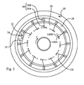
- FIG. 3 A second embodiment of the invention is shown in figure 3 .
- This embodiment differs from the first embodiment in the way the leading edge portion of the blades is linked to the inner rotor.
- this second embodiment is identical with the first embodiment, so that similar or identical features will be referenced with identical reference numbers.
- each blade 36 is associated with a pair of pins 140A, 140B fixed to the inner rotor 26.
- the leading edge portion 36A of each blade abuts against one of the associated pins 140A.
- the leading edge portion 36A of the blade Due to the flexibility of the leading edge portion 36A of the blade, the leading edge portion assumes a first inclined position relative to the inner rotor, as depicted in full lines in figure 3 .
- the leading edge portion 36A of each blade abuts against the other associated pin 140B and assumes a second inclined position relative to the inner rotor, which is the mirror image of the first inclined position as depicted in broken lines in figure 3 .
- the blade can be made of a simple flexible plate 138 of metal.
- the air circulation can include one or more air paths through the motor casing.
- the outer mantle is optional.
- the mechanical pivot connection between the blades and the inner rotor may be reversed, with pins associated to the blades sliding in oblong or arcuate slides provided in the inner rotor.
- the bearing 30 for rotating the outer rotor with respect to the inner rotor can be supported on the inner rotor, on the motor shaft itself or on the motor casing.
- the fan could also be driven by a secondary shaft driven by the motor shaft, in which case the axis of rotation of the fan, which would still coincide with the axis of rotation of the drive shaft, would not necessarily coincide with the axis of rotation of the motor shaft.
- a dampening means may be added between the inner and outer rotor to dampen possible rotary vibration movement between the inner rotor and outer rotor.
- This friction means may involve friction plates and/or a fluid damper.
Landscapes
- Engineering & Computer Science (AREA)
- Mechanical Engineering (AREA)
- General Engineering & Computer Science (AREA)
- Power Engineering (AREA)
- Structures Of Non-Positive Displacement Pumps (AREA)
Abstract
Description
- The invention relates to a bidirectional centrifugal fan, and in particular a centrifugal fan for cooling a traction motor of a rail vehicle.
- Three types of cooling principles are common for electric traction motors: water cooling, 'forced ventilation' in which an external electric fan is used and 'self-ventilation' with a fan directly mounted to the motor shaft. As the third cooling system is the simplest and most robust principle, although with limited cooling capacity, it dominates the low speed vehicle segment i.e. metros and light rail vehicles, but it is also increasingly popular for regional and inter-city vehicles.
- Unfortunately the 'self-ventilated' motor concept is rather noisy, producing sound powers typically in the range 105-115 dBA at full motor speed, making the motor cooling system the dominating full speed noise source in certain applications. Both interior and exterior noise levels may be significantly affected.
- The rotor must normally be able to rotate in both directions. The standard solution is to apply a fan with straight radial blades. However, the air approaching the blades will have a significant flow angle relative to the blades, which causes large separation of the flow around the forward edge of the blades, which is highly undesirable both from acoustical and aerodynamic point of view. The fan becomes inefficient as an air-pump.
- Previous solutions to the present problem include application of a silencer system. However, such solutions introduce additional pressure drop leading to reduced flow. In addition, these solutions are often too bulky to fit in the limited space around the motor. Better would be to improve the flow about the leading edge of the fan blades and thereby reduce the noise and improve the fan efficiency.
- A centrifugal cooling fan with deformable blades is known from
US-A-2 370 600 . To prevent heavy increase of the cooling air flow at increasing speed, the fixed fan blades of the cooling air fan of the motor, which fan blades thereby operate with a constant angle of incidence, are provided with flexible extension parts. At increasing speed of the motor, these flexible parts are bent more and more outwards in a radial direction by the increasing centrifugal force and hence throttle the inlet openings of the fan to an increasing extent. However, this known solution has considerable disadvantages. It is difficult in practice to design the flexible parts of the fan blades such that they are mutually identical and at all speeds are bent out to exactly the same extent. For this reason, an uncontrollable unbalance of a cooling fan of this kind will easily arise. The service life and reliability of such a cooling fan also tend to become poor, among other things because vibrations of the flexible parts easily arise, which eventually leads to fatigue and fracture. Moreover, this fan is not adapted to bidirectional motors. - A centrifugal cooling fan for electric motors with an impeller having a plurality of stiff fan blades is described in
W09105397 - A lightweight impeller for a centrifugal pump is described in
W09218773 - The foregoing shortcomings of the prior art are addressed by the present invention. According to one aspect of the invention, there is provided a bidirectional centrifugal fan comprising:
- an inner rotor provided with connection means for connecting the inner rotor to a drive shaft rotating about a rotation axis;
- an outer rotor rotating about the rotation axis and positioned radially outwards of the inner rotor,
- bearing means for rotating the outer rotor with respect to the inner rotor about the rotation axis between at least a first angular position and a second angular position,
- blades having a resilient flexible leading edge portion hinged to the inner rotor and a radially extending trailing edge portion fixed to the outer rotor, so as to move between a first inclined position and a second inclined position with respect to the inner rotor when the outer rotor moves between the first angular position and the second angular position.
- The outer rotor constitute an inertia mass, which upon acceleration of the inner rotor and of the blades will cause the blades to bend. The blades can change their inclination with the speed and/or the direction of the fan rotation such that optimized aerodynamic flow conditions are reached at all times. The pressure build-up on the blades during rotation can be used to adjust the blade shape so that no external actuator is needed. The position of the outer rotor with respect to the inner rotor is stable thanks to the torque resulting from the aerodynamic pressure on the blades. By aligning the flow and blade at the leading edge the flow separation causing noise and pressure loss is removed. These benefits are gained without need for extra space. The inclination of the blades is controlled by the angular movement of the outer rotor with respect to the inner rotor. This ensures that the blades will all assume the same inclination at any point in time. Uncontrolled flapping of the blades, imbalance or vibration are therefore limited.
- According to a preferred embodiment, each of the blades is associated to a radial plane of symmetry such that the second inclined position and the first inclined position are symmetrical with respect to the radial plane of symmetry. The blades in the second inclined position form a mirror image of the blades in the first inclined position. This symmetry ensures that the fan is fully reversible, with identical behaviour in both directions of rotation.
- Each blade may comprise a radially extending trailing edge portion, which is fixed to the outer rotor. This trailing edge portion is preferably not deformable and has a radial plane of symmetry, which ensures identical performance in both directions of rotation.
- According to a preferred embodiment, each of the blades pivots about an associated pivot axis parallel to the axis of rotation. The blades can also be movable in translation relative to associated pivot axis. According to one embodiment, each of the blades comprises a metal band folded in two halves around a pin fixed to the inner rotor, which constitutes the pivot axis.
- According to another preferred embodiment, each of the blades is associated with two abutments fixed relative to the inner rotor so that the leading edge of each of the blades abuts against one of the associated abutments in the first inclined position and against the other one of the associated abutments in the second inclined position. This alternative embodiment is simpler from design and less sensitive to fatigue of the blades, although less appealing from an aerodynamic point of view.
- Abutments may be provided for limiting the angular position of the outer rotor with respect to the inner rotor. A dampening means may be added between the inner and outer rotor to dampen possible rotary vibration movement between the inner rotor and outer rotor. This friction means may involve friction plates and/or a fluid damper.
- The fan comprises an air inlet proximate the leading edge portions of the blades and a radial outlet located radially outside the second rotor.
- According to a second aspect of the invention, there is provided a traction motor for a rail vehicle, provided with a drive shaft and a bidirectional fan as described hereinbefore, connected to the drive shaft.
- Other advantages and features of the invention will become more clearly apparent from the following description of a specific embodiment of the invention given as non-restrictive example only and represented in the accompanying drawings in which:
-
figure 1 illustrates a section of a traction motor provided with a centrifugal fan according to one embodiment of the invention, along a lines B-B offigure 2 ; -
figure 2 is a cross-section of the fan offigure 1 by a plane C-C offigure 1 ; and -
figure 3 is a cross-section of a centrifugal fan according to another embodiment of the invention. - Referring to
figure 1 , anelectric traction motor 10 for a rail vehicle is housed in acasing 12 provided with a pair of bearings (not shown) for supporting adrive shaft 16 of the motor. The motor is assumed to be arranged for operation in both directions with variable speed and may consist of, for example, a dc motor or of a frequency converter-supplied ac motor. The rotary axis of themotor shaft 16 is designated A-A in the figures. Themotor casing 12 is received in a surroundingmantle 18, with provision of an air gap defining anannular volume 20 around themotor casing 12. Theannular volume 20 is open at an inletaxial end 22 and at an axially opposite end (not shown). One end of themotor shaft 16 protrudes from an end wall of themotor casing 12 and is connected to afan 24 located at theinlet end 22 of theannular volume 20. - The cooling
fan 24, which is of centrifugal type, sucks fresh air into theinlet 22 and drives the cooling air through itsoutlet 21 and through the coolingvolume 20 between themotor casing 12 and themantle 18 past the motor. The path of the cooling airflow is schematically shown by the lines designated D in the figure. The motor casing may be provided with fins (not shown) for increasing the heat exchange. - As shown in
figure 2 , thefan 24 includes aninner rotor 26 mounted on themotor shaft 16 for rotation therewith about the motor shaft axis A-A, and anouter rotor 28, which is journalled on the inner rotor via aroller bearing 30, so as to be freely rotatable about the rotation axis A-A relative to theinner rotor 26 between a first and a second angular position, defined byabutment pins 32 fixed to the outer rotor and astop 34 fixed to the inner rotor. - The fan is provided with a plurality of
blades 36, twelve in the embodiment offigure 2 , which extend in a general radial direction between the inner rotor and the outer rotor. Theblades 36 are equally spaced along the circumference of the rotor. Each blade presents a deformableleading end portion 36A and a rigid trailingend portion 36B positioned radially outwards of the leading end portion. The trailingend portion 36B of each blade is fixed to theouter rotor 28 and extends in a direction parallel to a radial plane. Preferably, the shape of the trailing end portion is symmetrical with respect to a radial plane. Theleading end portion 36A of each blade is made of athin metal band 38 bent over apivot pin 40 fixed to theinner rotor 26, the ends of the bent metal band being fixed to the trailingend portion 36B of the blade. Thebent metal band 38 defines anoblong pocket 42 for receiving thepin 40, allowing both rotation and limited translation of theblade 36 with respect to thepin 40. The pin defines a pivot axis E-E for theleading edge portion 36A of the blade, which is parallel to the rotation axis of the motor shaft. - Upon rotation of the
motor shaft 16 in one direction F, the inner rotor rotates. The inertia of theouter rotor 28 causes the flexibleleading edge portion 36A of the blades to bend in the direction of rotation while the outer rotor rotates in the direction opposite to F with respect to the inner rotor. When the speed or rotation increases, the bending of the blades increases until thestop 34 comes into abutment with one of thepins 32. The corresponding position of the blades is shown in full lines infigure 2 . If the motor shaft rotates in the opposite position, the blades move in the opposite direction as shown in broken lines infigure 2 . - A second embodiment of the invention is shown in
figure 3 . This embodiment differs from the first embodiment in the way the leading edge portion of the blades is linked to the inner rotor. In all other respects, this second embodiment is identical with the first embodiment, so that similar or identical features will be referenced with identical reference numbers. In this second embodiment, eachblade 36 is associated with a pair ofpins 140A, 140B fixed to theinner rotor 26. When theouter rotor 28 is in the first angular position in relation to the inner rotor, the leadingedge portion 36A of each blade abuts against one of the associated pins 140A. Due to the flexibility of theleading edge portion 36A of the blade, the leading edge portion assumes a first inclined position relative to the inner rotor, as depicted in full lines infigure 3 . In the second angular position orrotors edge portion 36A of each blade abuts against the other associatedpin 140B and assumes a second inclined position relative to the inner rotor, which is the mirror image of the first inclined position as depicted in broken lines infigure 3 . In this embodiment, the blade can be made of a simpleflexible plate 138 of metal. - The invention is not limited to the embodiments described hereinbefore. The air circulation can include one or more air paths through the motor casing. The outer mantle is optional. The mechanical pivot connection between the blades and the inner rotor may can be reversed, with pins associated to the blades sliding in oblong or arcuate slides provided in the inner rotor.
- The bearing 30 for rotating the outer rotor with respect to the inner rotor can be supported on the inner rotor, on the motor shaft itself or on the motor casing. The fan could also be driven by a secondary shaft driven by the motor shaft, in which case the axis of rotation of the fan, which would still coincide with the axis of rotation of the drive shaft, would not necessarily coincide with the axis of rotation of the motor shaft.
- A dampening means may be added between the inner and outer rotor to dampen possible rotary vibration movement between the inner rotor and outer rotor. This friction means may involve friction plates and/or a fluid damper.
Claims (12)
- A bidirectional centrifugal fan comprising:- an inner rotor provided with connection means for connecting the inner rotor to a drive shaft rotating about a rotation axis;- an outer rotor rotating about the rotation axis and positioned radially outwards of the inner rotor,- bearing means for rotating the outer rotor with respect to the inner rotor about the rotation axis between at least a first angular position and a second angular position,- blades having a resilient flexible leading edge portion linked to the inner rotor and a radially extending trailing edge portion fixed to the outer rotor, so as to pivot between a first inclined position and a second inclined position with respect to the inner rotor when the outer rotor moves between the first angular position and the second angular position.
- The bidirectional fan of claim 1, wherein each of the blades is associated to a radial plane of symmetry such that the second inclined position and the first inclined position are symmetrical with respect to the radial plane of symmetry.
- The bidirectional fan of claim 1 or claim 2, wherein each of the blades pivots about an associated pivot axis fixed relative to the inner rotor and parallel to the axis of rotation.
- The bidirectional fan of claim 3, wherein each of the blades is movable in translation relative to associated pivot axis.
- The bidirectional fan of claim 1 or claim 2, wherein each of the blades is associated with two associated abutments fixed relative to the inner rotor so that the leading edge of each of the blades abuts against one of the associated abutments in the first inclined position and against the other one of the associated abutments in the second inclined position.
- The bidirectional fan of any one of the preceding claims, wherein each trailing edge portion is stiff.
- The bidirectional fan of any one of the preceding claims, wherein each of the blades comprises a metal band folded in two halves around a pin fixed to the inner rotor.
- The bidirectional fan of any one of the preceding claims, further comprising abutments for limiting the angular position of the outer rotor with respect to the inner rotor.
- The bidirectional fan of any one of the preceding claims, further comprising dampening means for dampening the rotation of the outer rotor with respect to the inner rotor.
- A traction motor for a rail vehicle, provided with a drive shaft and a bidirectional fan according to any one of the preceding claims, connected to the drive shaft.
- The traction motor of claim 10, further comprising an air inlet proximate the leading edge portions of the blades.
- The traction motor of claim 10 or claim 11, further comprising a radial outlet located radially outwards of the second rotor.
Priority Applications (2)
| Application Number | Priority Date | Filing Date | Title |
|---|---|---|---|
| AT08290729T ATE509204T1 (en) | 2008-07-28 | 2008-07-28 | BIDIRECTIONAL CENTRAL FAN |
| EP08290729A EP2149712B1 (en) | 2008-07-28 | 2008-07-28 | Bidirectional centrifugal fan |
Applications Claiming Priority (1)
| Application Number | Priority Date | Filing Date | Title |
|---|---|---|---|
| EP08290729A EP2149712B1 (en) | 2008-07-28 | 2008-07-28 | Bidirectional centrifugal fan |
Publications (2)
| Publication Number | Publication Date |
|---|---|
| EP2149712A1 true EP2149712A1 (en) | 2010-02-03 |
| EP2149712B1 EP2149712B1 (en) | 2011-05-11 |
Family
ID=39938314
Family Applications (1)
| Application Number | Title | Priority Date | Filing Date |
|---|---|---|---|
| EP08290729A Not-in-force EP2149712B1 (en) | 2008-07-28 | 2008-07-28 | Bidirectional centrifugal fan |
Country Status (2)
| Country | Link |
|---|---|
| EP (1) | EP2149712B1 (en) |
| AT (1) | ATE509204T1 (en) |
Cited By (8)
| Publication number | Priority date | Publication date | Assignee | Title |
|---|---|---|---|---|
| CN102332782A (en) * | 2011-09-23 | 2012-01-25 | 宁波菲仕电机技术有限公司 | Air cooling device of servo motor |
| US20120063892A1 (en) * | 2010-09-14 | 2012-03-15 | General Electric Company | Bidirectional fan having self-adjusting vane |
| PT109849A (en) * | 2017-01-11 | 2018-07-11 | Fernando Jose Teixeira Estevao Ferreira | FLEECE WITH FLEXIBLE PADS |
| CN108777529A (en) * | 2018-07-27 | 2018-11-09 | 深圳市南硕明泰科技有限公司 | A kind of transmission of scroll spring is fastenedly connected the cell phone vibrator with heat sinking function |
| CN109415118A (en) * | 2016-04-03 | 2019-03-01 | 欧梯维特公司 | Cycloidal rotors or thrusters optimized for performance and airflow |
| US10378552B2 (en) | 2016-05-17 | 2019-08-13 | Toshiba International Corporation | Multidirectional fan systems and methods |
| CN112953075A (en) * | 2021-03-08 | 2021-06-11 | 珠海格力电器股份有限公司 | Centrifugal fan blade, fan and air conditioner |
| EP3595144B1 (en) * | 2018-07-11 | 2025-10-15 | ALSTOM Holdings | Traction device with integrated fan |
Citations (7)
| Publication number | Priority date | Publication date | Assignee | Title |
|---|---|---|---|---|
| US1882961A (en) * | 1928-11-02 | 1932-10-18 | Ass Elect Ind | Fan or blower |
| DE662032C (en) * | 1935-03-29 | 1938-07-02 | Siemens Schuckertwerke Akt Ges | Circulating fan with low noise development |
| US2370600A (en) | 1943-11-11 | 1945-02-27 | Gen Electric | Centrifugal fan |
| FR2595417A1 (en) | 1986-03-04 | 1987-09-11 | Curtila Serge | Device with blades of the turbine, fan, pump or other type |
| WO1991005397A1 (en) | 1989-09-27 | 1991-04-18 | Asea Brown Boveri Ab | Radial type cooling fan for electric motors |
| WO1992018773A1 (en) | 1991-04-10 | 1992-10-29 | Sten Zeilon | Impeller for centrifugal pump |
| EP1544474A2 (en) * | 2003-12-18 | 2005-06-22 | TCG Unitech Systemtechnik GmbH | Radial pump |
-
2008
- 2008-07-28 AT AT08290729T patent/ATE509204T1/en not_active IP Right Cessation
- 2008-07-28 EP EP08290729A patent/EP2149712B1/en not_active Not-in-force
Patent Citations (7)
| Publication number | Priority date | Publication date | Assignee | Title |
|---|---|---|---|---|
| US1882961A (en) * | 1928-11-02 | 1932-10-18 | Ass Elect Ind | Fan or blower |
| DE662032C (en) * | 1935-03-29 | 1938-07-02 | Siemens Schuckertwerke Akt Ges | Circulating fan with low noise development |
| US2370600A (en) | 1943-11-11 | 1945-02-27 | Gen Electric | Centrifugal fan |
| FR2595417A1 (en) | 1986-03-04 | 1987-09-11 | Curtila Serge | Device with blades of the turbine, fan, pump or other type |
| WO1991005397A1 (en) | 1989-09-27 | 1991-04-18 | Asea Brown Boveri Ab | Radial type cooling fan for electric motors |
| WO1992018773A1 (en) | 1991-04-10 | 1992-10-29 | Sten Zeilon | Impeller for centrifugal pump |
| EP1544474A2 (en) * | 2003-12-18 | 2005-06-22 | TCG Unitech Systemtechnik GmbH | Radial pump |
Cited By (9)
| Publication number | Priority date | Publication date | Assignee | Title |
|---|---|---|---|---|
| US20120063892A1 (en) * | 2010-09-14 | 2012-03-15 | General Electric Company | Bidirectional fan having self-adjusting vane |
| US8662846B2 (en) * | 2010-09-14 | 2014-03-04 | General Electric Company | Bidirectional fan having self-adjusting vane |
| CN102332782A (en) * | 2011-09-23 | 2012-01-25 | 宁波菲仕电机技术有限公司 | Air cooling device of servo motor |
| CN109415118A (en) * | 2016-04-03 | 2019-03-01 | 欧梯维特公司 | Cycloidal rotors or thrusters optimized for performance and airflow |
| US10378552B2 (en) | 2016-05-17 | 2019-08-13 | Toshiba International Corporation | Multidirectional fan systems and methods |
| PT109849A (en) * | 2017-01-11 | 2018-07-11 | Fernando Jose Teixeira Estevao Ferreira | FLEECE WITH FLEXIBLE PADS |
| EP3595144B1 (en) * | 2018-07-11 | 2025-10-15 | ALSTOM Holdings | Traction device with integrated fan |
| CN108777529A (en) * | 2018-07-27 | 2018-11-09 | 深圳市南硕明泰科技有限公司 | A kind of transmission of scroll spring is fastenedly connected the cell phone vibrator with heat sinking function |
| CN112953075A (en) * | 2021-03-08 | 2021-06-11 | 珠海格力电器股份有限公司 | Centrifugal fan blade, fan and air conditioner |
Also Published As
| Publication number | Publication date |
|---|---|
| EP2149712B1 (en) | 2011-05-11 |
| ATE509204T1 (en) | 2011-05-15 |
Similar Documents
| Publication | Publication Date | Title |
|---|---|---|
| EP2149712B1 (en) | Bidirectional centrifugal fan | |
| US6244818B1 (en) | Fan guard structure for additional supercharging function | |
| JP3071456U (en) | Fan with series blades | |
| US20080063528A1 (en) | Turbine wheel | |
| WO2007141968A1 (en) | Electric supercharger | |
| US10352188B2 (en) | Centrifugal turbo machine having stretchable and variable diffuser vane | |
| CN109506296B (en) | Cross-flow fan blade, cross-flow fan and air conditioner | |
| JP2010525211A (en) | Radial impeller | |
| EP1792054B1 (en) | Radial variable area diffuser for a radial compressor | |
| CN102628453A (en) | Centrifugal compressor having variable geometry diffuser and method thereof | |
| CN112343840B (en) | Fans and electrical equipment | |
| RU2367825C2 (en) | Higher flow axial impeller | |
| JP2007517159A5 (en) | ||
| CN110985438A (en) | Centrifugal fan with variable-amplitude blades | |
| JP3981143B1 (en) | Power generator | |
| AU2019268133A1 (en) | Motor | |
| JP4423919B2 (en) | Centrifugal blower and air conditioner using the same | |
| SE464550B (en) | RADIAL TYPE COOL FAN FOR ELECTRIC MOTORS | |
| JP2011169192A (en) | Variable diffuser of centrifugal compressor for supercharger | |
| JP7375694B2 (en) | centrifugal compressor | |
| JP6632927B2 (en) | Rotating device | |
| US11346366B2 (en) | Rotating diffuser in centrifugal compressor | |
| JP7826147B2 (en) | Axial flow fan | |
| RU2427727C2 (en) | Propeller of reversible axial fan | |
| KR20170116754A (en) | High pressure centrifugal impeller |
Legal Events
| Date | Code | Title | Description |
|---|---|---|---|
| PUAI | Public reference made under article 153(3) epc to a published international application that has entered the european phase |
Free format text: ORIGINAL CODE: 0009012 |
|
| AK | Designated contracting states |
Kind code of ref document: A1 Designated state(s): AT BE BG CH CY CZ DE DK EE ES FI FR GB GR HR HU IE IS IT LI LT LU LV MC MT NL NO PL PT RO SE SI SK TR |
|
| AX | Request for extension of the european patent |
Extension state: AL BA MK RS |
|
| 17P | Request for examination filed |
Effective date: 20100716 |
|
| 17Q | First examination report despatched |
Effective date: 20100817 |
|
| AKX | Designation fees paid |
Designated state(s): AT BE BG CH CY CZ DE DK EE ES FI FR GB GR HR HU IE IS IT LI LT LU LV MC MT NL NO PL PT RO SE SI SK TR |
|
| GRAP | Despatch of communication of intention to grant a patent |
Free format text: ORIGINAL CODE: EPIDOSNIGR1 |
|
| GRAS | Grant fee paid |
Free format text: ORIGINAL CODE: EPIDOSNIGR3 |
|
| GRAA | (expected) grant |
Free format text: ORIGINAL CODE: 0009210 |
|
| AK | Designated contracting states |
Kind code of ref document: B1 Designated state(s): AT BE BG CH CY CZ DE DK EE ES FI FR GB GR HR HU IE IS IT LI LT LU LV MC MT NL NO PL PT RO SE SI SK TR |
|
| REG | Reference to a national code |
Ref country code: GB Ref legal event code: FG4D |
|
| REG | Reference to a national code |
Ref country code: CH Ref legal event code: EP |
|
| REG | Reference to a national code |
Ref country code: IE Ref legal event code: FG4D |
|
| REG | Reference to a national code |
Ref country code: DE Ref legal event code: R096 Ref document number: 602008006881 Country of ref document: DE Effective date: 20110622 |
|
| REG | Reference to a national code |
Ref country code: NL Ref legal event code: VDEP Effective date: 20110511 |
|
| PG25 | Lapsed in a contracting state [announced via postgrant information from national office to epo] |
Ref country code: NO Free format text: LAPSE BECAUSE OF FAILURE TO SUBMIT A TRANSLATION OF THE DESCRIPTION OR TO PAY THE FEE WITHIN THE PRESCRIBED TIME-LIMIT Effective date: 20110811 Ref country code: LT Free format text: LAPSE BECAUSE OF FAILURE TO SUBMIT A TRANSLATION OF THE DESCRIPTION OR TO PAY THE FEE WITHIN THE PRESCRIBED TIME-LIMIT Effective date: 20110511 Ref country code: SE Free format text: LAPSE BECAUSE OF FAILURE TO SUBMIT A TRANSLATION OF THE DESCRIPTION OR TO PAY THE FEE WITHIN THE PRESCRIBED TIME-LIMIT Effective date: 20110511 Ref country code: PT Free format text: LAPSE BECAUSE OF FAILURE TO SUBMIT A TRANSLATION OF THE DESCRIPTION OR TO PAY THE FEE WITHIN THE PRESCRIBED TIME-LIMIT Effective date: 20110912 |
|
| PG25 | Lapsed in a contracting state [announced via postgrant information from national office to epo] |
Ref country code: AT Free format text: LAPSE BECAUSE OF FAILURE TO SUBMIT A TRANSLATION OF THE DESCRIPTION OR TO PAY THE FEE WITHIN THE PRESCRIBED TIME-LIMIT Effective date: 20110511 Ref country code: ES Free format text: LAPSE BECAUSE OF FAILURE TO SUBMIT A TRANSLATION OF THE DESCRIPTION OR TO PAY THE FEE WITHIN THE PRESCRIBED TIME-LIMIT Effective date: 20110822 Ref country code: LV Free format text: LAPSE BECAUSE OF FAILURE TO SUBMIT A TRANSLATION OF THE DESCRIPTION OR TO PAY THE FEE WITHIN THE PRESCRIBED TIME-LIMIT Effective date: 20110511 Ref country code: SI Free format text: LAPSE BECAUSE OF FAILURE TO SUBMIT A TRANSLATION OF THE DESCRIPTION OR TO PAY THE FEE WITHIN THE PRESCRIBED TIME-LIMIT Effective date: 20110511 Ref country code: IS Free format text: LAPSE BECAUSE OF FAILURE TO SUBMIT A TRANSLATION OF THE DESCRIPTION OR TO PAY THE FEE WITHIN THE PRESCRIBED TIME-LIMIT Effective date: 20110911 Ref country code: GR Free format text: LAPSE BECAUSE OF FAILURE TO SUBMIT A TRANSLATION OF THE DESCRIPTION OR TO PAY THE FEE WITHIN THE PRESCRIBED TIME-LIMIT Effective date: 20110812 Ref country code: BE Free format text: LAPSE BECAUSE OF FAILURE TO SUBMIT A TRANSLATION OF THE DESCRIPTION OR TO PAY THE FEE WITHIN THE PRESCRIBED TIME-LIMIT Effective date: 20110511 Ref country code: CY Free format text: LAPSE BECAUSE OF FAILURE TO SUBMIT A TRANSLATION OF THE DESCRIPTION OR TO PAY THE FEE WITHIN THE PRESCRIBED TIME-LIMIT Effective date: 20110511 Ref country code: FI Free format text: LAPSE BECAUSE OF FAILURE TO SUBMIT A TRANSLATION OF THE DESCRIPTION OR TO PAY THE FEE WITHIN THE PRESCRIBED TIME-LIMIT Effective date: 20110511 |
|
| PG25 | Lapsed in a contracting state [announced via postgrant information from national office to epo] |
Ref country code: MT Free format text: LAPSE BECAUSE OF FAILURE TO SUBMIT A TRANSLATION OF THE DESCRIPTION OR TO PAY THE FEE WITHIN THE PRESCRIBED TIME-LIMIT Effective date: 20110511 Ref country code: NL Free format text: LAPSE BECAUSE OF FAILURE TO SUBMIT A TRANSLATION OF THE DESCRIPTION OR TO PAY THE FEE WITHIN THE PRESCRIBED TIME-LIMIT Effective date: 20110511 |
|
| PG25 | Lapsed in a contracting state [announced via postgrant information from national office to epo] |
Ref country code: CZ Free format text: LAPSE BECAUSE OF FAILURE TO SUBMIT A TRANSLATION OF THE DESCRIPTION OR TO PAY THE FEE WITHIN THE PRESCRIBED TIME-LIMIT Effective date: 20110511 Ref country code: EE Free format text: LAPSE BECAUSE OF FAILURE TO SUBMIT A TRANSLATION OF THE DESCRIPTION OR TO PAY THE FEE WITHIN THE PRESCRIBED TIME-LIMIT Effective date: 20110511 |
|
| PG25 | Lapsed in a contracting state [announced via postgrant information from national office to epo] |
Ref country code: DK Free format text: LAPSE BECAUSE OF FAILURE TO SUBMIT A TRANSLATION OF THE DESCRIPTION OR TO PAY THE FEE WITHIN THE PRESCRIBED TIME-LIMIT Effective date: 20110511 Ref country code: PL Free format text: LAPSE BECAUSE OF FAILURE TO SUBMIT A TRANSLATION OF THE DESCRIPTION OR TO PAY THE FEE WITHIN THE PRESCRIBED TIME-LIMIT Effective date: 20110511 Ref country code: SK Free format text: LAPSE BECAUSE OF FAILURE TO SUBMIT A TRANSLATION OF THE DESCRIPTION OR TO PAY THE FEE WITHIN THE PRESCRIBED TIME-LIMIT Effective date: 20110511 Ref country code: MC Free format text: LAPSE BECAUSE OF NON-PAYMENT OF DUE FEES Effective date: 20110731 Ref country code: RO Free format text: LAPSE BECAUSE OF FAILURE TO SUBMIT A TRANSLATION OF THE DESCRIPTION OR TO PAY THE FEE WITHIN THE PRESCRIBED TIME-LIMIT Effective date: 20110511 |
|
| PLBE | No opposition filed within time limit |
Free format text: ORIGINAL CODE: 0009261 |
|
| STAA | Information on the status of an ep patent application or granted ep patent |
Free format text: STATUS: NO OPPOSITION FILED WITHIN TIME LIMIT |
|
| 26N | No opposition filed |
Effective date: 20120214 |
|
| REG | Reference to a national code |
Ref country code: FR Ref legal event code: ST Effective date: 20120330 |
|
| REG | Reference to a national code |
Ref country code: IE Ref legal event code: MM4A |
|
| PG25 | Lapsed in a contracting state [announced via postgrant information from national office to epo] |
Ref country code: FR Free format text: LAPSE BECAUSE OF NON-PAYMENT OF DUE FEES Effective date: 20110801 Ref country code: DE Free format text: LAPSE BECAUSE OF NON-PAYMENT OF DUE FEES Effective date: 20120201 |
|
| REG | Reference to a national code |
Ref country code: DE Ref legal event code: R119 Ref document number: 602008006881 Country of ref document: DE Effective date: 20120201 |
|
| PG25 | Lapsed in a contracting state [announced via postgrant information from national office to epo] |
Ref country code: HR Free format text: LAPSE BECAUSE OF FAILURE TO SUBMIT A TRANSLATION OF THE DESCRIPTION OR TO PAY THE FEE WITHIN THE PRESCRIBED TIME-LIMIT Effective date: 20111123 Ref country code: IT Free format text: LAPSE BECAUSE OF FAILURE TO SUBMIT A TRANSLATION OF THE DESCRIPTION OR TO PAY THE FEE WITHIN THE PRESCRIBED TIME-LIMIT Effective date: 20110511 |
|
| PG25 | Lapsed in a contracting state [announced via postgrant information from national office to epo] |
Ref country code: IE Free format text: LAPSE BECAUSE OF NON-PAYMENT OF DUE FEES Effective date: 20110728 |
|
| REG | Reference to a national code |
Ref country code: CH Ref legal event code: PL |
|
| GBPC | Gb: european patent ceased through non-payment of renewal fee |
Effective date: 20120728 |
|
| PG25 | Lapsed in a contracting state [announced via postgrant information from national office to epo] |
Ref country code: GB Free format text: LAPSE BECAUSE OF NON-PAYMENT OF DUE FEES Effective date: 20120728 Ref country code: LI Free format text: LAPSE BECAUSE OF NON-PAYMENT OF DUE FEES Effective date: 20120731 Ref country code: CH Free format text: LAPSE BECAUSE OF NON-PAYMENT OF DUE FEES Effective date: 20120731 |
|
| PG25 | Lapsed in a contracting state [announced via postgrant information from national office to epo] |
Ref country code: LU Free format text: LAPSE BECAUSE OF NON-PAYMENT OF DUE FEES Effective date: 20110728 |
|
| PG25 | Lapsed in a contracting state [announced via postgrant information from national office to epo] |
Ref country code: BG Free format text: LAPSE BECAUSE OF FAILURE TO SUBMIT A TRANSLATION OF THE DESCRIPTION OR TO PAY THE FEE WITHIN THE PRESCRIBED TIME-LIMIT Effective date: 20110811 |
|
| PG25 | Lapsed in a contracting state [announced via postgrant information from national office to epo] |
Ref country code: TR Free format text: LAPSE BECAUSE OF FAILURE TO SUBMIT A TRANSLATION OF THE DESCRIPTION OR TO PAY THE FEE WITHIN THE PRESCRIBED TIME-LIMIT Effective date: 20110511 |
|
| PG25 | Lapsed in a contracting state [announced via postgrant information from national office to epo] |
Ref country code: HU Free format text: LAPSE BECAUSE OF FAILURE TO SUBMIT A TRANSLATION OF THE DESCRIPTION OR TO PAY THE FEE WITHIN THE PRESCRIBED TIME-LIMIT Effective date: 20110511 |
|
| PG25 | Lapsed in a contracting state [announced via postgrant information from national office to epo] |
Ref country code: HR Free format text: LAPSE BECAUSE OF FAILURE TO SUBMIT A TRANSLATION OF THE DESCRIPTION OR TO PAY THE FEE WITHIN THE PRESCRIBED TIME-LIMIT Effective date: 20110511 |