EP2149701A2 - Wind turbine blade tip shapes - Google Patents
Wind turbine blade tip shapes Download PDFInfo
- Publication number
- EP2149701A2 EP2149701A2 EP09166037A EP09166037A EP2149701A2 EP 2149701 A2 EP2149701 A2 EP 2149701A2 EP 09166037 A EP09166037 A EP 09166037A EP 09166037 A EP09166037 A EP 09166037A EP 2149701 A2 EP2149701 A2 EP 2149701A2
- Authority
- EP
- European Patent Office
- Prior art keywords
- chord
- blade
- tip
- leading edge
- approximately
- Prior art date
- Legal status (The legal status is an assumption and is not a legal conclusion. Google has not performed a legal analysis and makes no representation as to the accuracy of the status listed.)
- Withdrawn
Links
Images
Classifications
-
- F—MECHANICAL ENGINEERING; LIGHTING; HEATING; WEAPONS; BLASTING
- F03—MACHINES OR ENGINES FOR LIQUIDS; WIND, SPRING, OR WEIGHT MOTORS; PRODUCING MECHANICAL POWER OR A REACTIVE PROPULSIVE THRUST, NOT OTHERWISE PROVIDED FOR
- F03D—WIND MOTORS
- F03D1/00—Wind motors with rotation axis substantially parallel to the air flow entering the rotor
- F03D1/06—Rotors
- F03D1/0608—Rotors characterised by their aerodynamic shape
- F03D1/0633—Rotors characterised by their aerodynamic shape of the blades
-
- F—MECHANICAL ENGINEERING; LIGHTING; HEATING; WEAPONS; BLASTING
- F03—MACHINES OR ENGINES FOR LIQUIDS; WIND, SPRING, OR WEIGHT MOTORS; PRODUCING MECHANICAL POWER OR A REACTIVE PROPULSIVE THRUST, NOT OTHERWISE PROVIDED FOR
- F03D—WIND MOTORS
- F03D1/00—Wind motors with rotation axis substantially parallel to the air flow entering the rotor
- F03D1/06—Rotors
- F03D1/0608—Rotors characterised by their aerodynamic shape
- F03D1/0633—Rotors characterised by their aerodynamic shape of the blades
- F03D1/0641—Rotors characterised by their aerodynamic shape of the blades of the section profile of the blades, i.e. aerofoil profile
-
- F—MECHANICAL ENGINEERING; LIGHTING; HEATING; WEAPONS; BLASTING
- F05—INDEXING SCHEMES RELATING TO ENGINES OR PUMPS IN VARIOUS SUBCLASSES OF CLASSES F01-F04
- F05B—INDEXING SCHEME RELATING TO WIND, SPRING, WEIGHT, INERTIA OR LIKE MOTORS, TO MACHINES OR ENGINES FOR LIQUIDS COVERED BY SUBCLASSES F03B, F03D AND F03G
- F05B2240/00—Components
- F05B2240/20—Rotors
- F05B2240/30—Characteristics of rotor blades, i.e. of any element transforming dynamic fluid energy to or from rotational energy and being attached to a rotor
- F05B2240/301—Cross-section characteristics
-
- F—MECHANICAL ENGINEERING; LIGHTING; HEATING; WEAPONS; BLASTING
- F05—INDEXING SCHEMES RELATING TO ENGINES OR PUMPS IN VARIOUS SUBCLASSES OF CLASSES F01-F04
- F05B—INDEXING SCHEME RELATING TO WIND, SPRING, WEIGHT, INERTIA OR LIKE MOTORS, TO MACHINES OR ENGINES FOR LIQUIDS COVERED BY SUBCLASSES F03B, F03D AND F03G
- F05B2250/00—Geometry
- F05B2250/70—Shape
- F05B2250/71—Shape curved
-
- F—MECHANICAL ENGINEERING; LIGHTING; HEATING; WEAPONS; BLASTING
- F05—INDEXING SCHEMES RELATING TO ENGINES OR PUMPS IN VARIOUS SUBCLASSES OF CLASSES F01-F04
- F05B—INDEXING SCHEME RELATING TO WIND, SPRING, WEIGHT, INERTIA OR LIKE MOTORS, TO MACHINES OR ENGINES FOR LIQUIDS COVERED BY SUBCLASSES F03B, F03D AND F03G
- F05B2260/00—Function
- F05B2260/96—Preventing, counteracting or reducing vibration or noise
-
- Y—GENERAL TAGGING OF NEW TECHNOLOGICAL DEVELOPMENTS; GENERAL TAGGING OF CROSS-SECTIONAL TECHNOLOGIES SPANNING OVER SEVERAL SECTIONS OF THE IPC; TECHNICAL SUBJECTS COVERED BY FORMER USPC CROSS-REFERENCE ART COLLECTIONS [XRACs] AND DIGESTS
- Y02—TECHNOLOGIES OR APPLICATIONS FOR MITIGATION OR ADAPTATION AGAINST CLIMATE CHANGE
- Y02E—REDUCTION OF GREENHOUSE GAS [GHG] EMISSIONS, RELATED TO ENERGY GENERATION, TRANSMISSION OR DISTRIBUTION
- Y02E10/00—Energy generation through renewable energy sources
- Y02E10/70—Wind energy
- Y02E10/72—Wind turbines with rotation axis in wind direction
-
- Y—GENERAL TAGGING OF NEW TECHNOLOGICAL DEVELOPMENTS; GENERAL TAGGING OF CROSS-SECTIONAL TECHNOLOGIES SPANNING OVER SEVERAL SECTIONS OF THE IPC; TECHNICAL SUBJECTS COVERED BY FORMER USPC CROSS-REFERENCE ART COLLECTIONS [XRACs] AND DIGESTS
- Y10—TECHNICAL SUBJECTS COVERED BY FORMER USPC
- Y10S—TECHNICAL SUBJECTS COVERED BY FORMER USPC CROSS-REFERENCE ART COLLECTIONS [XRACs] AND DIGESTS
- Y10S416/00—Fluid reaction surfaces, i.e. impellers
- Y10S416/02—Formulas of curves
-
- Y—GENERAL TAGGING OF NEW TECHNOLOGICAL DEVELOPMENTS; GENERAL TAGGING OF CROSS-SECTIONAL TECHNOLOGIES SPANNING OVER SEVERAL SECTIONS OF THE IPC; TECHNICAL SUBJECTS COVERED BY FORMER USPC CROSS-REFERENCE ART COLLECTIONS [XRACs] AND DIGESTS
- Y10—TECHNICAL SUBJECTS COVERED BY FORMER USPC
- Y10S—TECHNICAL SUBJECTS COVERED BY FORMER USPC CROSS-REFERENCE ART COLLECTIONS [XRACs] AND DIGESTS
- Y10S416/00—Fluid reaction surfaces, i.e. impellers
- Y10S416/05—Variable camber or chord length
Definitions
- the subject matter described here generally relates to fluid reaction surfaces with specific blade structures, and, more particularly, to wind turbine blade tip shapes.
- a wind turbine is a machine for converting the kinetic energy in wind into mechanical energy. If the mechanical energy is used directly by the machinery, such as to pump water or to grind wheat, then the wind turbine may be referred to as a windmill. Similarly, if the mechanical energy is converted to electricity, then the machine may also be referred to as a wind generator or wind power plant.
- Wind turbines are typically categorized according to the vertical or horizontal axis about which the blades rotate.
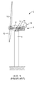
- One so-called horizontal-axis wind generator is schematically illustrated in Figure 1 and available from General Electric Company.
- This particular configuration for a wind turbine 2 includes a tower 4 supporting a nacelle 6 enclosing a drive train 8.
- the blades 10 are arranged on a hub to form a "rotor" at one end of the drive train 8 outside of the nacelle 6.
- the rotating blades 10 drive a gearbox 12 connected to an electrical generator 14 at the other end of the drive train 8 arranged inside the nacelle 6 along with a control system 16 that receives input from an anemometer 18.
- the blades 10 generate lift and capture momentum from moving air that is then imparted to a rotor as the blades spin in the "rotor plane.”
- Each blade is typically secured at its “root” end, and then “spans” radially “outboard” to a free, “tip” end. The distance from the tip to the root, at the opposite end of the blade, is called the “span.”
- the front, or “leading edge,” of the blade connects the forward-most points of the blade that first contact the air.
- the rear, or “trailing edge,” of the blade is where airflow that has been separated by the leading edge rejoins after passing over the suction and pressure surfaces of the blade.
- chord line connects the leading and trailing edges of a cross section of the blade 10 that is oriented normal to the radial direction.
- the length of the chord line is simply referred to as the “chord.” Since many blades 10 change their chord over the span, the chord length is referred to as the “root chord,” near the root, and the “tip chord,” near the tip of the blade.
- the chord lines are arranged in the “chord planes” that extend through the corresponding pressure and suction surfaces of the blade.
- the center of the chord plane, or “chord plane center line” is formed by a line on the chord plane which is halfway between the leading and trailing edge of the blade 10. Multiple “shear web planes” are arranged perpendicular to the to the chord plane.
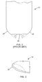
- FIG. 2 is schematic planform view of the tip portion of the blade 10 shown in FIG. 1 where the tip chord 20 forms a "leading edge tip chord angle" ⁇ with the leading edge 22, and a “trailing edge tip chord angle” ⁇ with the trailing edge 24.
- a blade for a wind turbine including a chord of length "c" positioned with a leading edge tip chord angle and trailing edge tip chord angle of between approximately 45 and 75 degrees; a tip having a shear web plane radii distribution in the ranges of L/c (%) R/c (%) 0-10% 1.03-3.68% 30-40% 2.91 - 5.79 % 60-70% 1.77-2.5 % 90-100 % 0.229-.350 % where "L/c” is a range of an approximate normalized location along the chord line expressed as a percentage of the chord length from a leading edge of the blade; and where "R/c” is a range of an approximate normalized shear web plane tip radius, expressed as a percentage of the chord length, for each normalized location L/c.
- FIGs. are not necessarily drawn to scale, but use the same reference numerals to designate corresponding parts throughout each of the several views, and in which:
- the outer edge of the tip is provided with multiple curvatures in various shear web planes.
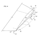
- the first shear web plane curvature 41 is arranged at about 0% to 10% of the chord from the leading edge; the second shear web plane curvature 42 is arranged at about 30% to 40% of the chord from the leading edge; the third shear web plane curvature 43 is arranged at about 60% to 70% of the chord from the leading edge; and the fourth shear web plane curvature 44 is arranged at about 90% to 100% of the chord from the leading edge.
- any other number of curvatures may also be arranged at these and/or other locations along the chord plane 46.
- chord line 20 is positioned with a leading edge tip chord angle ⁇ and trailing edge tip chord angle ⁇ in a wide range of between approximately 45 and 75 degrees, a narrower range of approximately 50 and 70, and an even narrower range of between 55 and 65 degrees.
- the curvatures 41-44 are semicircular with the following shear web plane radii distribution defining a range of radius values for "R" in millimeters at each location: Location L/c (%) R (mm) R/c (%) 41 0-10% 3.6-7mm 1.03-3.68% 42 30-40% 10 - 11 mm 2.91 - 5.79 % 43 60-70% 3.6 - 6.2 mm 1.77-2.5 % 44 90-100 % 0.5 - 0.8 mm 0.229-.350 %
- ratios listed above may be used with other chord lengths and/or at other distances along the chord 20 from the leading edge 22 of the blade. It is also expected that suitable results may be achieved by varying the above values for "R" and/or "R/c" over a range of values between plus or minus approximately ten percent, a narrower range of between plus or minus approximately five percent, and an even narrower range of between approximately one percent.
- curvature configurations may also be used, including, but not limited to any portion or combination of various types of algebraic curves, caustic curves, cissoids, conchoids, conic sections, elliptic curves, parabolic curves, hyperbolic curves, general plane curves, implicit curves, inverse curves, involutes and evolutes, pedal curves, polar curves, pursuit curves, radial curves, roulettes, strophoids, rational, transcendental, fractal, continuous, discontinuous, and/or piecewise curves.
- algebraic curves including, but not limited to any portion or combination of various types of algebraic curves, caustic curves, cissoids, conchoids, conic sections, elliptic curves, parabolic curves, hyperbolic curves, general plane curves, implicit curves, inverse curves, involutes and evolutes, pedal curves, polar curves, pursuit curves, radial curves, roulettes, strophoids, rational, transcend
- FIG. 4 illustrates the suction surface 42 projected spanwise to tangent point 48 and the pressure surface projected to tangent point 50.
- the outermost portions of the curvatures 41 through 44 are then connected with a spline 52, such as a B-spline, that completes a frame for the surface. The remaining surfaces of the tip are then smoothly laid over that frame.
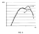
- FIG. 5 is a noise spectra model plot showing sound pressure level in dBA on the vertical axis versus frequency in Hz on the horizontal axis for the blade 10 illustrated in FIG. 3 with a 350 mm chord length in the table above where the leading edge tip chord angle ⁇ and trailing edge tip chord angle ⁇ are approximately 60 degrees.
- Plot line 54 corresponds to the blade without the cap 30 while plot line 56 corresponds to the blade 10 with the cap.
- a notable reduction in sound pressure level occurs at midrange frequencies when the cap 30 is used. It is expected that additional reductions in noise level will be available when the tip is formed from a porous material such as disclosed in commonly-owned co-pending U.S. Application Serial No. 11/798377 (Attorney Docket No: 206018) which is incorporated by reference here.
- a blade for a wind turbine comprising a chord of length "c" positioned with a leading edge tip chord angle and trailing edge tip chord angle of between approximately 45 and 75 degrees; a tip having a shear web plane radii distribution in the ranges of L/c (%) R/c (%) 0-10% 1.03-3.68% 30-40% 2.91 - 5.79 % 60-70% 1.77-2.5 % 90-100 % 0.229-.350 % wherein "L/c” is a range of an approximate normalized location along the chord length expressed as a percentage of the chord length from a leading edge of the blade; and wherein "R/c” is a range of an approximate normalized shear web plane tip radius, expressed as a percentage of the chord line length, for each normalized location L/c.
- leading edge tip chord angle and trailing edge tip chord angle are between approximately 50 and 70 degrees.
- leading edge tip chord angle and trailing edge tip chord angle are between approximately 55 and 65 degrees.
- at least one of the leading edge tip chord angle and trailing edge tip chord angle is approximately 60 degrees.
- an outermost edge of the tip comprises a B-spline.
- an outermost edge of the tip comprises a B-spline. 7.
- a blade for a wind turbine comprising a chord of length "c" positioned with a leading edge tip chord angle and trailing edge tip chord angle of between approximately 55 and 65 degrees; a tip having a shear web plane radii distribution in the ranges of L/c (%) R/c (%) 0-10% 0.927 -1.13 % 30-40% 2.62-3.20% wherein "L/c” is a range of an approximate normalized location along the chord length expressed as a percentage of the chord length from a leading edge of the blade; and wherein "R/c” is a range of an approximate normalized shear web plane tip radius, expressed as a percentage of the chord line length, for each normalized location L/c.
- the shear web plane radii distribution further comprises the ranges of L/c (%) R/c (%) 60 - 70 % 1.59 - 1.95 % 90-100 % 0.206-.252 % 11.
- the blade recited in clause 9 or 10 wherein the shear web plane radii distribution further comprises approximately L/c (%) R/c (%) 0 - 10 % 1.03 % 30-40% 2.91 % 60-70% 1.77 % 90-100 % 0.229 % 12.
- each of the leading edge tip chord angle and trailing edge tip chord angles are approximately 60 degrees.
- each of the leading edge tip chord angle and trailing edge tip chord angle are approximately 60 degrees.
Landscapes
- Engineering & Computer Science (AREA)
- Physics & Mathematics (AREA)
- Fluid Mechanics (AREA)
- Life Sciences & Earth Sciences (AREA)
- Sustainable Development (AREA)
- Sustainable Energy (AREA)
- Chemical & Material Sciences (AREA)
- Combustion & Propulsion (AREA)
- Mechanical Engineering (AREA)
- General Engineering & Computer Science (AREA)
- Wind Motors (AREA)
Abstract

Description
- The subject matter described here generally relates to fluid reaction surfaces with specific blade structures, and, more particularly, to wind turbine blade tip shapes.
- A wind turbine is a machine for converting the kinetic energy in wind into mechanical energy. If the mechanical energy is used directly by the machinery, such as to pump water or to grind wheat, then the wind turbine may be referred to as a windmill. Similarly, if the mechanical energy is converted to electricity, then the machine may also be referred to as a wind generator or wind power plant.
- Wind turbines are typically categorized according to the vertical or horizontal axis about which the blades rotate. One so-called horizontal-axis wind generator is schematically illustrated in
Figure 1 and available from General Electric Company. This particular configuration for awind turbine 2 includes atower 4 supporting anacelle 6 enclosing adrive train 8. Theblades 10 are arranged on a hub to form a "rotor" at one end of thedrive train 8 outside of thenacelle 6. The rotatingblades 10 drive a gearbox 12 connected to anelectrical generator 14 at the other end of thedrive train 8 arranged inside thenacelle 6 along with a control system 16 that receives input from ananemometer 18. - The
blades 10 generate lift and capture momentum from moving air that is then imparted to a rotor as the blades spin in the "rotor plane." Each blade is typically secured at its "root" end, and then "spans" radially "outboard" to a free, "tip" end. The distance from the tip to the root, at the opposite end of the blade, is called the "span." The front, or "leading edge," of the blade connects the forward-most points of the blade that first contact the air. The rear, or "trailing edge," of the blade is where airflow that has been separated by the leading edge rejoins after passing over the suction and pressure surfaces of the blade. - A "chord line" connects the leading and trailing edges of a cross section of the
blade 10 that is oriented normal to the radial direction. The length of the chord line is simply referred to as the "chord." Sincemany blades 10 change their chord over the span, the chord length is referred to as the "root chord," near the root, and the "tip chord," near the tip of the blade. The chord lines are arranged in the "chord planes" that extend through the corresponding pressure and suction surfaces of the blade. The center of the chord plane, or "chord plane center line," is formed by a line on the chord plane which is halfway between the leading and trailing edge of theblade 10. Multiple "shear web planes" are arranged perpendicular to the to the chord plane. - The resulting shape of the
blade 10, when viewed perpendicular to the direction of flow, is called the "planform." For example,FIG. 2 is schematic planform view of the tip portion of theblade 10 shown inFIG. 1 where thetip chord 20 forms a "leading edge tip chord angle" α with the leadingedge 22, and a "trailing edge tip chord angle" β with thetrailing edge 24. - The noise and power performance of the
wind turbine blades 10 depends, in part, upon vortex development at the tip of the blade. Various techniques have been proposed to control this vortex development. For example, commonly-owned co-pendingU.S. Application Serial No. 11/827,532 U.S. Application Serial No. 12129997 - Various drawbacks associated with such conventional approaches are addressed here in by providing, in various embodiments, a blade for a wind turbine including a chord of length "c" positioned with a leading edge tip chord angle and trailing edge tip chord angle of between approximately 45 and 75 degrees; a tip having a shear web plane radii distribution in the ranges of
L/c (%) R/c (%) 0-10% 1.03-3.68% 30-40% 2.91 - 5.79 % 60-70% 1.77-2.5 % 90-100 % 0.229-.350 % - Various aspects of this technology will now be described with reference to the following figures ("FIGs.") which are not necessarily drawn to scale, but use the same reference numerals to designate corresponding parts throughout each of the several views, and in which:
-
FIG. 1 is a schematic side view of a conventional wind generator. -
FIG. 2 is a schematic planform view of a tip portion of the conventional blade shown inFIG. 1 -
FIG. 3 is an orthographic view of a cap secured to the tip of the blade shown inFIGs 1 and2 . -
FIG. 4 is a schematic orthographic view of a profile for shaping the cap shown inFIG. 3 . -
FIG. 5 is a noise spectra plot. -
FIG. 3 is an orthographic view of acap 30 that is secured to the tip of theblade 10 shown inFIGs 1 and2 . However, thecap 30 may also be configured to fit with the tips of other wind turbine blades. For example, thecap 30 may be provided with a bolt or mounting bracket that is secured to a drain hole of the blade. In addition, some or allof thecap 30 may be configured as an integral part of any wind turbine blade. Thecap 30 may sometimes be referred to as a "side edge cap." -
FIG. 4 is a schematic, orthographic view of a profile for the tip of a wind turbine blade such as the cap shown inFIG. 3 . InFIG.4 , the leading edge tip chord angle α and the trailing edge tip chord angle β are illustrated as inFIG. 2 with respect to the chordplane center line 40. For example, the leading edge tip chord angle α and trailing edge tip chord angle β may be substantially the same magnitude, in a range of between about 75 degrees and 45 degrees, or a smaller range of between about 50 degrees and 70 degrees, or an even smaller range of between about 65 degrees and 55 degrees. Alternatively the leading edge tip chord angle α and trailing edge tip chord angle β may have different magnitudes within these ranges, or they may both be about 60 degrees. If anexisting blade 10 does not have atip chord 20 with the appropriate angles, then the blade can be shortened ("under built") or lengthened ("over built") in order to obtain a tip chord having the appropriate leading edge tip chord angle α and trailing edge tip chord angle β. - In the tip profile of
FIG. 4 , the outer edge of the tip is provided with multiple curvatures in various shear web planes. In this example, the first shearweb plane curvature 41 is arranged at about 0% to 10% of the chord from the leading edge; the second shearweb plane curvature 42 is arranged at about 30% to 40% of the chord from the leading edge; the third shearweb plane curvature 43 is arranged at about 60% to 70% of the chord from the leading edge; and the fourth shearweb plane curvature 44 is arranged at about 90% to 100% of the chord from the leading edge. However, any other number of curvatures may also be arranged at these and/or other locations along thechord plane 46. - In the example illustrated here, the
chord line 20 is positioned with a leading edge tip chord angle α and trailing edge tip chord angle β in a wide range of between approximately 45 and 75 degrees, a narrower range of approximately 50 and 70, and an even narrower range of between 55 and 65 degrees. The curvatures 41-44 are semicircular with the following shear web plane radii distribution defining a range of radius values for "R" in millimeters at each location:Location L/c (%) R (mm) R/c (%) 41 0-10% 3.6-7mm 1.03-3.68% 42 30-40% 10 - 11 mm 2.91 - 5.79 % 43 60-70% 3.6 - 6.2 mm 1.77-2.5 % 44 90-100 % 0.5 - 0.8 mm 0.229-.350 % - Various shear web plane radii distributions may fall within these ranges. For example, the following table lists typical values for R and R/c in millimeters at specific locations for three different chord lengths in millimeters where the leading edge tip chord angle α and trailing edge tip chord angle β are both approximately 60 degrees:
Location L/c (%) R (mm) R/c (%) R (mm) R/c (%) R (mm) R/c (%) 41 5 % 7 mm 3.68 % 4 mm 2.00 % 3.6 mm 1.03 % 42 35 % 11 mm 5.79 % 10 mm 5.00 % 10.2 mm 2.91 % 43 65 % 3.5 mm 1.84 % 5 mm 2.50 % 6.2 mm 1.77 % 44 95 % 0.5 mm .263 % 0.7 mm 0.350 % 0.8 mm 0.229 % Chord 190 mm 200 mm 350 mm - However, the ratios listed above may be used with other chord lengths and/or at other distances along the
chord 20 from the leadingedge 22 of the blade. It is also expected that suitable results may be achieved by varying the above values for "R" and/or "R/c" over a range of values between plus or minus approximately ten percent, a narrower range of between plus or minus approximately five percent, and an even narrower range of between approximately one percent. In addition to such semicircular curvature configurations, other curvature configurations may also be used, including, but not limited to any portion or combination of various types of algebraic curves, caustic curves, cissoids, conchoids, conic sections, elliptic curves, parabolic curves, hyperbolic curves, general plane curves, implicit curves, inverse curves, involutes and evolutes, pedal curves, polar curves, pursuit curves, radial curves, roulettes, strophoids, rational, transcendental, fractal, continuous, discontinuous, and/or piecewise curves. - Once the
curvatures 41 through 44 are positioned, the (top) suction and (bottom) pressure surfaces are extended or projected spanwise to points that are tangential to thecurvatures 41 through 44. For example, with regard to the second shear web plane curvature,FIG. 4 illustrates thesuction surface 42 projected spanwise to tangentpoint 48 and the pressure surface projected totangent point 50. The outermost portions of thecurvatures 41 through 44 are then connected with aspline 52, such as a B-spline, that completes a frame for the surface. The remaining surfaces of the tip are then smoothly laid over that frame. -
FIG. 5 is a noise spectra model plot showing sound pressure level in dBA on the vertical axis versus frequency in Hz on the horizontal axis for theblade 10 illustrated inFIG. 3 with a 350 mm chord length in the table above where the leading edge tip chord angle α and trailing edge tip chord angle β are approximately 60 degrees.Plot line 54 corresponds to the blade without thecap 30 whileplot line 56 corresponds to theblade 10 with the cap. A notable reduction in sound pressure level occurs at midrange frequencies when thecap 30 is used. It is expected that additional reductions in noise level will be available when the tip is formed from a porous material such as disclosed in commonly-owned co-pendingU.S. Application Serial No. 11/798377 (Attorney Docket No: 206018) which is incorporated by reference here. - It should be emphasized that the embodiments described above, and particularly any "preferred" embodiments, are merely examples of various implementations that have been set forth here to provide a clear understanding of various aspects of this technology. One of ordinary skill will be able to alter many of these embodiments without substantially departing from scope of protection defined solely by the proper construction of the following claims.
- Various aspects and embodiments of the present invention are defined by the following numbered clauses:
1. A blade for a wind turbine, comprising
a chord of length "c" positioned with a leading edge tip chord angle and trailing edge tip chord angle of between approximately 45 and 75 degrees;
a tip having a shear web plane radii distribution in the ranges ofL/c (%) R/c (%) 0-10% 1.03-3.68% 30-40% 2.91 - 5.79 % 60-70% 1.77-2.5 % 90-100 % 0.229-.350 %
wherein "R/c" is a range of an approximate normalized shear web plane tip radius, expressed as a percentage of the chord line length, for each normalized location L/c.
2. The blade recited in clause 1, wherein the leading edge tip chord angle and trailing edge tip chord angle are between approximately 50 and 70 degrees.
3. The blade recited in any preceding clause, wherein the leading edge tip chord angle and trailing edge tip chord angle are between approximately 55 and 65 degrees.
4. The blade recited in any preceding clause, wherein at least one of the leading edge tip chord angle and trailing edge tip chord angle is approximately 60 degrees.
5. The blade recited in any preceding clause, wherein an outermost edge of the tip comprises a B-spline.
6. The blade recited in any preceding clause, wherein an outermost edge of the tip comprises a B-spline.
7. The blade recited in any preceding clause, wherein an outermost edge of the tip comprises a B-spline.
8. The blade recited in any preceding clause, wherein an outermost edge of the tip comprises a B-spline.
9. A blade for a wind turbine, comprising
a chord of length "c" positioned with a leading edge tip chord angle and trailing edge tip chord angle of between approximately 55 and 65 degrees;
a tip having a shear web plane radii distribution in the ranges ofL/c (%) R/c (%) 0-10% 0.927 -1.13 % 30-40% 2.62-3.20%
wherein "R/c" is a range of an approximate normalized shear web plane tip radius, expressed as a percentage of the chord line length, for each normalized location L/c.
10. The blade recited in clause 9, wherein the shear web plane radii distribution further comprises the ranges ofL/c (%) R/c (%) 60 - 70 % 1.59 - 1.95 % 90-100 % 0.206-.252 % clause 9 or 10, wherein the shear web plane radii distribution further comprises approximatelyL/c (%) R/c (%) 0 - 10 % 1.03 % 30-40% 2.91 % 60-70% 1.77 % 90-100 % 0.229 %
13. The blade recited in any of clauses 9 to 12, wherein the chord length is approximately 350 mm.
14. The blade recited in any of clauses 9 to 13, wherein the chord length is approximately 350 mm.
15. The blade recited in any of clauses 9 to 14, wherein at least one of the leading edge tip chord angle and trailing edge tip chord angle is approximately 60 degrees.
16. The blade recited in any of clauses 9 to 15, wherein at least one of the leading edge tip chord angle and trailing edge tip chord angle is approximately 60 degrees.
17. The blade recited in any of clauses 9 to 16, wherein at least one of the leading edge tip chord angle and trailing edge tip chord angle is approximately 60 degrees.
18. The blade recited in any of clauses 9 to 17, wherein at least one of the leading edge tip chord angle and trailing edge tip chord angles is approximately 60 degrees.
19. The blade recited in any of clauses 9 to 18, wherein each of the leading edge tip chord angle and trailing edge tip chord angles are approximately 60 degrees.
20. The blade recited in any of clauses 9 to 19, wherein each of the leading edge tip chord angle and trailing edge tip chord angle are approximately 60 degrees.
Claims (10)
- A blade (10) for a wind turbine (2), comprising:a chord (20) of length "c" positioned with a leading edge tip chord angle (α) and trailing edge tip chord angle (β) of between approximately 45 and 75 degrees;a tip having a shear web plane radii distribution in the ranges of
L/c (%) R/c (%) 0-10% 1.03-3.68% 30-40% 2.91 - 5.79 % 60-70% 1.77-2.5 % 90-100 % 0.229-.350 %
wherein "R/c" is a range of an approximate normalized shear web plane tip radius (41-44), expressed as a percentage of the chord line length, for each normalized location L/c. - A blade (10) for a wind turbine (2), comprising:a chord (20) of length "c" positioned with a leading edge tip chord angle (α) and trailing edge tip chord angle (β) of between approximately 45 and 75 degrees;a tip having a shear web plane radii distribution in the ranges of
L/c (%) R/c (%) 0-10% 0.927 - 1.13 % 30-40% 2.62-3.20%
wherein "R/c" is a range of an approximate normalized shear web plane tip radius (41-44), expressed as a percentage of the chord line length, for each normalized location L/c. - The blade (10) recited in claim 2, wherein the shear web plane radii distribution further comprises the ranges of
L/c (%) R/c (%) 60 - 70 % 1.59- 1.95 % 90-100 % 0.206-.252 % - The blade (10) recited in any of claims 2 or 3, wherein the shear web plane radii distribution further comprises approximately
L/c (%) R/c (%) 0 - 10 % 1.03 % 30-40% 2.91 % 60-70% 1.77 % 90-100 % 0.229 % - The blade (10) recited in any of claims 1 to 4, wherein the leading edge tip chord angle (α) and trailing edge tip chord angle (β) are between approximately 50 and 70 degrees.
- The blade (10) recited in any of claims 1 to 4, wherein the leading edge tip chord angle (α) and trailing edge tip chord angle (β) are between approximately 55 and 65 degrees.
- The blade (10) recited in any of claims 1 to 4, wherein at least one of the leading edge tip chord angle (α) and trailing edge tip chord angle (β) are approximately 60 degrees.
- The blade (10) recited in any of claims 1 to 4, wherein both of the leading edge tip chord angle (α) and trailing edge tip chord angle (β) are approximately 60 degrees.
- The blade (10) recited in any of claims 1 to 8, wherein an outermost edge of the tip comprises a B-spline (52).
- The blade (10) recited in any of claims 1 to 9, wherein the chord length is approximately 350 mm.
Applications Claiming Priority (1)
| Application Number | Priority Date | Filing Date | Title |
|---|---|---|---|
| US12/182,184 US7854595B2 (en) | 2008-07-30 | 2008-07-30 | Wind turbine blade tip shapes |
Publications (2)
| Publication Number | Publication Date |
|---|---|
| EP2149701A2 true EP2149701A2 (en) | 2010-02-03 |
| EP2149701A3 EP2149701A3 (en) | 2013-09-25 |
Family
ID=40937470
Family Applications (1)
| Application Number | Title | Priority Date | Filing Date |
|---|---|---|---|
| EP09166037.3A Withdrawn EP2149701A3 (en) | 2008-07-30 | 2009-07-21 | Wind turbine blade tip shapes |
Country Status (3)
| Country | Link |
|---|---|
| US (1) | US7854595B2 (en) |
| EP (1) | EP2149701A3 (en) |
| CN (1) | CN101644229B (en) |
Cited By (1)
| Publication number | Priority date | Publication date | Assignee | Title |
|---|---|---|---|---|
| US10414486B2 (en) | 2015-11-30 | 2019-09-17 | General Electric Company | Airfoil for a rotary machine including a propellor assembly |
Families Citing this family (3)
| Publication number | Priority date | Publication date | Assignee | Title |
|---|---|---|---|---|
| AT507091B1 (en) * | 2008-09-22 | 2010-02-15 | Walter Enthammer | TURBOMACHINE |
| US8100648B2 (en) * | 2009-01-28 | 2012-01-24 | Carr Fred K | Submersible rotor design |
| US10690111B2 (en) | 2016-12-02 | 2020-06-23 | General Electric Company | Wind turbine rotor blade |
Family Cites Families (10)
| Publication number | Priority date | Publication date | Assignee | Title |
|---|---|---|---|---|
| US2962260A (en) * | 1954-12-13 | 1960-11-29 | United Aircraft Corp | Sweep back in blading |
| US4334828A (en) * | 1980-01-21 | 1982-06-15 | United Technologies Corporation | Helicopter blade with a tip having a selected combination of sweep, taper and anhedral to improve hover efficiency |
| FR2507149A1 (en) * | 1981-06-05 | 1982-12-10 | Onera (Off Nat Aerospatiale) | END OF BLADE FOR AN AIRCRAFT ROTARY SAIL AND ROTARY VESSEL PROVIDED WITH SUCH EXTREMITES OF BLADE |
| FR2617118B1 (en) * | 1987-06-29 | 1992-08-21 | Aerospatiale | CURVED END BLADE FOR AIRCRAFT TURNING WING |
| FR2755941B1 (en) * | 1996-11-19 | 1999-01-15 | Eurocopter France | ARROW BLADE AT ARROW FOR AIRCRAFT TURNING WING |
| DE10300284A1 (en) * | 2003-01-02 | 2004-07-15 | Aloys Wobben | Turbine rotor blade for wind-powered energy plant has tip region curved or angled in direction of rotor blade trailing edge |
| ES2318925B1 (en) * | 2005-09-22 | 2010-02-11 | GAMESA INNOVATION & TECHNOLOGY, S.L. | AEROGENERATOR WITH A BLADE ROTOR THAT REDUCES NOISE. |
| CN101169101B (en) * | 2007-11-08 | 2011-04-20 | 申振华 | Wind turbine impeller installed with blown flap wing-like vane |
| US8419371B2 (en) * | 2008-05-30 | 2013-04-16 | General Electric Company | Wind turbine blades with twisted and tapered tips |
| US8061996B2 (en) * | 2008-05-30 | 2011-11-22 | General Electric Company | Wind turbine blade planforms with twisted and tapered tips |
-
2008
- 2008-07-30 US US12/182,184 patent/US7854595B2/en not_active Expired - Fee Related
-
2009
- 2009-07-21 EP EP09166037.3A patent/EP2149701A3/en not_active Withdrawn
- 2009-07-30 CN CN2009101658309A patent/CN101644229B/en not_active Expired - Fee Related
Cited By (2)
| Publication number | Priority date | Publication date | Assignee | Title |
|---|---|---|---|---|
| US10414486B2 (en) | 2015-11-30 | 2019-09-17 | General Electric Company | Airfoil for a rotary machine including a propellor assembly |
| US11136109B2 (en) | 2015-11-30 | 2021-10-05 | General Electric Company | Airfoil for a rotary machine including a propellor assembly |
Also Published As
| Publication number | Publication date |
|---|---|
| CN101644229A (en) | 2010-02-10 |
| US7854595B2 (en) | 2010-12-21 |
| CN101644229B (en) | 2013-07-31 |
| EP2149701A3 (en) | 2013-09-25 |
| US20100028157A1 (en) | 2010-02-04 |
Similar Documents
| Publication | Publication Date | Title |
|---|---|---|
| US11053911B2 (en) | Serrated trailing edge panel for a wind turbine blade | |
| US8414261B2 (en) | Noise reducer for rotor blade in wind turbine | |
| US8523515B2 (en) | Noise reducer for rotor blade in wind turbine | |
| CN101649807B (en) | Wind turbine blade planforms with twisted and tapered tips | |
| EP2828521B1 (en) | Winglet for a wind turbine rotor blade | |
| US20090074585A1 (en) | Wind turbine blades with trailing edge serrations | |
| US20090324416A1 (en) | Wind turbine blades with multiple curvatures | |
| US9982654B2 (en) | Wind turbine with an offset suction side | |
| US20110150664A1 (en) | Aeroacoustic rotor blade for a wind turbine, and wind turbine equipped therewith | |
| US10746157B2 (en) | Noise reducer for a wind turbine rotor blade having a cambered serration | |
| EP2128434B1 (en) | Wind turbine blades with twisted and tapered tips | |
| AU2007361564B2 (en) | Wind turbine blade and wind power generator using the same | |
| US9039380B2 (en) | Winglet for a wind turbine rotor blade | |
| EP2128435B1 (en) | Wind turbine blade with twisted tip | |
| EP2149701A2 (en) | Wind turbine blade tip shapes | |
| JP5433554B2 (en) | Wind turbine blade, wind power generator equipped with the wind turbine blade, and wind turbine blade design method | |
| CN211900866U (en) | Wind power blade and horizontal shaft wind driven generator | |
| WO2020041225A1 (en) | Rotor blade assembly having twist, chord, and thickness distribution for improved performance |
Legal Events
| Date | Code | Title | Description |
|---|---|---|---|
| PUAI | Public reference made under article 153(3) epc to a published international application that has entered the european phase |
Free format text: ORIGINAL CODE: 0009012 |
|
| AK | Designated contracting states |
Kind code of ref document: A2 Designated state(s): AT BE BG CH CY CZ DE DK EE ES FI FR GB GR HR HU IE IS IT LI LT LU LV MC MK MT NL NO PL PT RO SE SI SK SM TR |
|
| AX | Request for extension of the european patent |
Extension state: AL BA RS |
|
| PUAL | Search report despatched |
Free format text: ORIGINAL CODE: 0009013 |
|
| RIC1 | Information provided on ipc code assigned before grant |
Ipc: F03D 1/06 20060101AFI20130814BHEP |
|
| AK | Designated contracting states |
Kind code of ref document: A3 Designated state(s): AT BE BG CH CY CZ DE DK EE ES FI FR GB GR HR HU IE IS IT LI LT LU LV MC MK MT NL NO PL PT RO SE SI SK SM TR |
|
| AX | Request for extension of the european patent |
Extension state: AL BA RS |
|
| 17P | Request for examination filed |
Effective date: 20140325 |
|
| RBV | Designated contracting states (corrected) |
Designated state(s): AT BE BG CH CY CZ DE DK EE ES FI FR GB GR HR HU IE IS IT LI LT LU LV MC MK MT NL NO PL PT RO SE SI SK SM TR |
|
| 17Q | First examination report despatched |
Effective date: 20141111 |
|
| GRAP | Despatch of communication of intention to grant a patent |
Free format text: ORIGINAL CODE: EPIDOSNIGR1 |
|
| INTG | Intention to grant announced |
Effective date: 20180620 |
|
| STAA | Information on the status of an ep patent application or granted ep patent |
Free format text: STATUS: THE APPLICATION IS DEEMED TO BE WITHDRAWN |
|
| 18D | Application deemed to be withdrawn |
Effective date: 20181031 |