EP2149683A1 - Internal combustion engine - Google Patents
Internal combustion engine Download PDFInfo
- Publication number
- EP2149683A1 EP2149683A1 EP09160046A EP09160046A EP2149683A1 EP 2149683 A1 EP2149683 A1 EP 2149683A1 EP 09160046 A EP09160046 A EP 09160046A EP 09160046 A EP09160046 A EP 09160046A EP 2149683 A1 EP2149683 A1 EP 2149683A1
- Authority
- EP
- European Patent Office
- Prior art keywords
- oil
- introduction port
- generator
- chamber
- oil introduction
- Prior art date
- Legal status (The legal status is an assumption and is not a legal conclusion. Google has not performed a legal analysis and makes no representation as to the accuracy of the status listed.)
- Granted
Links
- 238000002485 combustion reaction Methods 0.000 title claims abstract description 16
- 239000003921 oil Substances 0.000 claims description 241
- 239000010687 lubricating oil Substances 0.000 claims description 5
- 238000000034 method Methods 0.000 abstract description 4
- 230000013011 mating Effects 0.000 description 15
- 239000000203 mixture Substances 0.000 description 6
- 239000000446 fuel Substances 0.000 description 4
- 235000014676 Phragmites communis Nutrition 0.000 description 3
- 239000002828 fuel tank Substances 0.000 description 3
- 238000005461 lubrication Methods 0.000 description 3
- 238000005192 partition Methods 0.000 description 3
- 230000000694 effects Effects 0.000 description 2
- 230000001050 lubricating effect Effects 0.000 description 2
- 230000000630 rising effect Effects 0.000 description 2
- 239000000567 combustion gas Substances 0.000 description 1
- 238000012790 confirmation Methods 0.000 description 1
- 230000005484 gravity Effects 0.000 description 1
- 238000012986 modification Methods 0.000 description 1
- 230000004048 modification Effects 0.000 description 1
- 239000000725 suspension Substances 0.000 description 1
Images




Classifications
-
- F—MECHANICAL ENGINEERING; LIGHTING; HEATING; WEAPONS; BLASTING
- F01—MACHINES OR ENGINES IN GENERAL; ENGINE PLANTS IN GENERAL; STEAM ENGINES
- F01M—LUBRICATING OF MACHINES OR ENGINES IN GENERAL; LUBRICATING INTERNAL COMBUSTION ENGINES; CRANKCASE VENTILATING
- F01M11/00—Component parts, details or accessories, not provided for in, or of interest apart from, groups F01M1/00 - F01M9/00
- F01M11/0004—Oilsumps
-
- F—MECHANICAL ENGINEERING; LIGHTING; HEATING; WEAPONS; BLASTING
- F02—COMBUSTION ENGINES; HOT-GAS OR COMBUSTION-PRODUCT ENGINE PLANTS
- F02F—CYLINDERS, PISTONS OR CASINGS, FOR COMBUSTION ENGINES; ARRANGEMENTS OF SEALINGS IN COMBUSTION ENGINES
- F02F7/00—Casings, e.g. crankcases
- F02F7/0065—Shape of casings for other machine parts and purposes, e.g. utilisation purposes, safety
- F02F7/0068—Adaptations for other accessories
-
- F—MECHANICAL ENGINEERING; LIGHTING; HEATING; WEAPONS; BLASTING
- F01—MACHINES OR ENGINES IN GENERAL; ENGINE PLANTS IN GENERAL; STEAM ENGINES
- F01M—LUBRICATING OF MACHINES OR ENGINES IN GENERAL; LUBRICATING INTERNAL COMBUSTION ENGINES; CRANKCASE VENTILATING
- F01M11/00—Component parts, details or accessories, not provided for in, or of interest apart from, groups F01M1/00 - F01M9/00
- F01M11/0004—Oilsumps
- F01M2011/0033—Oilsumps with special means for guiding the return of oil into the sump
-
- F—MECHANICAL ENGINEERING; LIGHTING; HEATING; WEAPONS; BLASTING
- F01—MACHINES OR ENGINES IN GENERAL; ENGINE PLANTS IN GENERAL; STEAM ENGINES
- F01M—LUBRICATING OF MACHINES OR ENGINES IN GENERAL; LUBRICATING INTERNAL COMBUSTION ENGINES; CRANKCASE VENTILATING
- F01M11/00—Component parts, details or accessories, not provided for in, or of interest apart from, groups F01M1/00 - F01M9/00
- F01M11/0004—Oilsumps
- F01M2011/0037—Oilsumps with different oil compartments
-
- F—MECHANICAL ENGINEERING; LIGHTING; HEATING; WEAPONS; BLASTING
- F01—MACHINES OR ENGINES IN GENERAL; ENGINE PLANTS IN GENERAL; STEAM ENGINES
- F01M—LUBRICATING OF MACHINES OR ENGINES IN GENERAL; LUBRICATING INTERNAL COMBUSTION ENGINES; CRANKCASE VENTILATING
- F01M11/00—Component parts, details or accessories, not provided for in, or of interest apart from, groups F01M1/00 - F01M9/00
- F01M11/0004—Oilsumps
- F01M2011/005—Oilsumps with special anti-turbulence means, e.g. anti-foaming means or intermediate plates
Definitions
- the present invention relates to an internal combustion engine having a lubrication structure for circulating an oil.
- an internal combustion engine having a lubrication structure for circulatorily supplying an oil to sliding parts has been known.
- a structure has been adopted in which the oil is supplied to the sliding parts (e.g., a generator, a cam chain, etc.) by use of an oil pump, and the oil having lubricated the sliding parts flows down into an oil sump chamber provided at a lower part of the crankcase.
- the oil having flowed down into and reserved in the oil sump chamber is pumped up by the oil pump, and is again circulatorily supplied to the sliding parts (refer to, for example, Japanese Patent Document No. JP-A-2005-61386 ).
- bubbles may mix into the oil during when the oil flows down, and the bubbles mixed in the oil in the oil sump chamber may be pumped up by the oil pump.
- the splashed oil comes directly into an oil introduction port of the oil sump chamber, the splashed oil impinges on the oil being reserved, making it easier for bubbles to mix into the oil.
- the present invention has been made in consideration of the above-mentioned circumstances, and it is an object of the invention to provide an internal combustion engine in which it can be made difficult for bubbles to mix into an oil in a flowing-down process of the oil.
- an internal combustion engine comprising: a generator chamber which is provided at a side part of a crank chamber and in which a cam chain and a generator are disposed; and an oil sump chamber which has an oil introduction port for receiving a lubricating oil coming from the generator chamber and which reserves the oil received through the oil introduction port, with a generator being disposed on the upper side of one end side of the oil introduction port, and with a side wall of the generator chamber extending on the upper side of the other end side of the oil introduction port; wherein in the generator chamber, there are provided a shielding rib which is disposed between the generator and the oil introduction port in side view and which extends skewly upward from the oil introduction port in the manner of covering one end side of the oil introduction port, and a guide rib extending from the side wall of the generator chamber in the manner of covering the other end side of the oil introduction port.
- a bottom wall of the generator chamber may be formed at such an inclination as to gradually rise from the one end side of the oil introduction port, and the shielding rib may be provided with a groove for guiding the oil from the bottom wall to the oil introduction port.
- the oil collected at the bottom wall of the generator chamber flows along the inclination to one end side of the shielding rib, and is then guided along the groove into the oil introduction port.
- the guide rib may be disposed so as to be above the shielding rib in the vertical direction and to overlap with the shielding rib in side view, and may be formed at such a downward inclination that an end part in the extension direction of the guide rib is located below the center of a crankshaft.
- the oil collected by the guide rib is further collected by the shielding rib.
- the oil splashed during the course of the cam chain coming into mesh with the sprocket provided on the crankshaft is received by the guide rib.
- a shielding rib which is disposed between the generator and the oil introduction port in side view and which extends skewly upward from the oil introduction port in the manner of covering one end side of the oil introduction port, and a guide rib which extends from a side wall of the generator chamber in the manner of covering the other end side of the oil introduction port. Therefore, the oil splashed from the generator is shielded by the shielding rib, and flows down the shielding rib to the oil introduction port. Consequently, the oil is prevented from directly entering the oil introduction port of the oil sump chamber, and generation of bubbles in the oil due to impingement of the splashed oil on the reserved oil can be prevented from occurring.
- the oil is collected by the guide rib and is guided to the oil introduction port. This also ensures that generation of bubbles in the oil due to impingement of the splashed oil on the reserved oil can be prevented from occurring.
- a bottom wall of the generator chamber is formed at such an inclination as to gradually rise from one end side of the oil introduction port, and the shielding rib is provided with a groove for guiding the oil from the bottom wall to the oil introduction port. Therefore, the oil collected at the bottom wall of the generator chamber flows along the inclination to one end side of the shielding rib, and is thereafter guided through the groove to the oil introduction port. Accordingly, the oil can be guided to the oil introduction port while preventing such a strong impingement (collision) that bubbles would mix into the oil.
- the guide rib is so disposed as to be above the shielding rib in the vertical direction and to overlap with the shielding rib in side view, and is formed at such a downward inclination that an end part in the extension direction of the guide rib is located below the center of a crankshaft. Therefore, the oil collected by the guide rib flows down onto the shielding rib, to be further collected by the shielding rib. Accordingly, the oil can be guided to the oil introduction port while obviating such a strong impingement (collision) that bubbles would mix into the oil.
- the guide rib receives the oil splashed during the course of the cam chain coming out of engagement with the sprocket provided on the crankshaft.
- the oil can be received by the guide rib in its course of being splashed most. Consequently, the splashed oil can be prevented from impinging on the oil reserved in the oil sump chamber, and generation of bubbles in the oil can be obviated thereby.
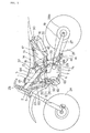
- FIG. 1 is a side view of an offroad motorcycle according to an embodiment of the present invention.
- a body frame 1 of this motorcycle includes a head pipe 2, main frames 3, center frames 4, a down frame 5 and lower frames 6, which are connected to one another in a loop form, and an engine 7 is supported on the inside thereof.
- the engine 7 has a cylinder 8 and a crankcase 9.
- the main frames 3, the center frames 4 and the lower frames 6 are provided in left-right pairs, whereas the head pipe 2 and the down frame 5 are provided as single members along the center of the vehicle body.
- the main frames 3 extend over the engine 7 rectilinearly and downwardly rearwards, and are connected to upper end parts of the center frames 4 which extend vertically on the rear side of the engine 7.
- the down frame 5 extends skewly downward on the front side of the engine 7, and is connected to front end parts of the lower frames 6 at its lower end part.
- the lower frames 6 are bent from a front side lower part of the engine 7 toward the lower side of the engine 7, extend substantially rectilinearly rearwards, and are connected to lower end parts of the center frames 4 at their rear end parts.
- the engine 7 is of a water-cooled four-cycle system.
- the cylinder 8 is provided at a front part of the crankcase 9 in an upright state with its axis substantially vertical, and has a cylinder block 10, a cylinder head 11, and a head cover 12 in this order from the lower side toward the upper side. With the cylinder 8 thus set upright, the engine 7 is made short in the front-rear direction, and the engine 7 is suited to an offroad vehicle.
- a fuel tank 13 is disposed on the upper side of the engine 7, and is supported on the main frames 3.
- An incorporated type fuel pump (see FIG. 7 ) is contained in the inside of the fuel tank 13, and a high-pressure fuel is supplied from the fuel pump to a throttle body 18 through a fuel supply pipe.
- a seat 14 is disposed on the rear side of the fuel tank 13, and is supported on seat rails 15 extending rearwards from the upper ends of the center frame 4.
- Rear frames 16 are disposed on the lower side of the seat rails 15.
- An air cleaner 17 is supported by the seat rails 15 and the rear frames 16, and intake into the cylinder head 11 is conducted through the throttle body 18 from the vehicle body rear side.
- An exhaust pipe 20 is provided at a front part of the cylinder 8.
- the exhaust pipe 20 extends from the front part of the cylinder 8 toward the front side of the crankcase 9, is bent to the right side, and is laid to extend rearwards on the right side of the vehicle body.
- a muffler 22 extends rearwards from the exhaust pipe 20.
- a rear end part of the muffler 22 is supported by the rear frames 16.
- a front fork 23 is supported by the head pipe 2, and a front wheel 24 supported by lower end parts of the front fork 23 is steered by a handle 25.
- a front end part of a rear arm 27 is swingably supported on the center frames 4 by a pivot shaft 26.
- a rear wheel 28 is supported on a rear end part of the rear arm 27, and is driven by a drive chain 19 wrapped around a drive sprocket 7a of the engine 7 and a driven sprocket 28a on the rear wheel 28.
- a cushion unit 29 of rear suspension is provided between the rear arm 27 and rear end parts of the center frames 4.
- symbol 60 denotes a radiator
- 61 denotes a rubber mount part thereof
- 62 and 63 denote engine mount parts
- 64 denotes an engine hanger.
- the engine 7 is supported on the center frames 4 also through the pivot shaft 26.
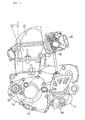
- FIG. 2 is a side view of the water-cooled four-cycle single-cylinder engine 7
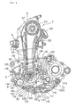
- FIG. 3 is a side part sectional view of the engine 7
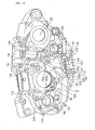
- FIG. 4 is a partial sectional view of the engine 7, showing a generator chamber 71
- FIG. 5 is a front view of FIG. 3 , specifically, a sectional view taken along line A-A of FIG. 3 .
- the engine 7 is composed of the cylinder block 10, the cylinder head 11, the head cover 12, and the crankcase 9, as above-mentioned.
- the crankcase 9 is assembled by a method in which a right-side case 9a and a left-side case 9b provided as a pair being splittable in the vehicle body width direction are coupled to each other at mating surfaces 80a, 80b (for details, see FIGS. 6 and 7 ) orthogonal to the rotational axis of the crankshaft 40.
- a crankcase cover 9c is attached to a left side surface of the crankcase 9 through a gasket (not shown), and a right-side case cover 9d (see FIG. 5 ) is attached to a right side surface of the crankcase 9.
- the cylinder head 11 is provided, on the vehicle body rear side thereof, with an intake port 30 through which a fuel-air mixture from the throttle body 18 is supplied into the engine 7.
- the intake port 30 is opened and closed through an intake valve 33 moved up and down by a cam 31 and a valve lifter 32 both provided inside the head cover 12, and the fuel-air mixture is supplied into a combustion chamber.
- the cylinder head 11 is provided with an exhaust port (not shown) on the vehicle body front side thereof, and a combustion gas generated in the combustion chamber is exhausted through the exhaust port.
- the cylinder block 10 is provided with a cylinder part 35 in which a piston 34 can be reciprocated in the vertical direction (more accurately, a direction slightly inclined toward a front upper side).
- crankshaft 40 located on the lower side of the piston 34, a main shaft 45 located on the vehicle body rear side of the crankshaft 40, and a drive shaft 50 located further on the vehicle body rear side of the main shaft 45 are provided inside the crankcase 9.
- Rotational axes of the crankshaft 40, the main shaft 45, and the drive shaft 50 are disposed parallel to one another, and motive power is transmitted to them by gears which will be described later.
- a primary reduction gear 46 rotated together with the crankshaft 40 is provided at a part on the vehicle body right side of the crankshaft 40.
- the primary reduction gear 46 is meshed with a housing gear 47a of a multiple disk clutch 47 disposed on the main shaft 45. This ensures that the rotational power of the crankshaft 40 is transmitted through the primary reduction gear 46 and the multiple disk clutch 47 to the main shaft 45.
- a generator 52 is attached to a left end part of the crankshaft 40.
- the generator 52 is located on the left side of the crankcase 9.
- a left outside part of the generator 52 is covered by a crankcase cover 9c.
- a cam chain 53 for transmitting the power of the crankshaft 40 to a camshaft 54 is disposed on the inner side (the cylinder head side) of the generator 52.
- the cam chain 53 is wrapped around a crankshaft sprocket 56 provided on the crankshaft 40 and a cam sprocket 57 provided on the camshaft 54, so as to transmit power to the camshaft 54.
- an oil pump 86 (indicated by dotted line in FIG. 6 ) for supplying a lubricating oil to sliding parts (a shaft part of the crankshaft 40, sliding parts of the cam chain 53 and the generator 52, and the like) inside the engine 7 is attached to the crankcase 9.
- the oil pump 86 is driven by power obtained from a pump gear 58 (see FIG. 5 ) provided on the crankshaft 40.
- an oil filter 59 is attached to the crankcase cover 9c, and an oil pump 86 is provided on the depth side of the oil filter 59 shown in FIG. 2 (on the side of the inside of the engine 7).
- the cam chain 53, the crankshaft sprocket 56, and the cam sprocket 57 mentioned above are disposed in a generator chamber 71 partitioned at a left side part of the crank chamber by a wall part 70.
- the generator chamber 71 is so configured that the oil having lubricated the camshaft 54 flows down to a lower part of the engine 7.
- a generator 52 is provided in the inside of the generator chamber 71.
- the cam chain 53 runs, and the lubricating oil coming mainly from the generator 52 and the cam chain 53 flows down into the oil introduction port 115, and passes through a strainer 117 into an oil sump chamber 100.
- the oil introduction port 115, the strainer 117, and the oil sump chamber 100 will be described later.
- FIG. 6 is a side view of the right-side case 9a of the crankcase 9 as viewed from the mating surface 80a side
- FIG. 7 is a side view of the left-side case 9b as viewed from the mating surface 80b side.
- the mating surface 80a shown in FIG. 6 and the mating surface 80b shown in FIG. 7 are hatched for permitting easy confirmation of these surfaces.
- FIG. 8 is a sectional view in the vehicle body width direction of an oil sump chamber 100 in the condition where the right-side and left-side cases 9a and 9b are mated with each other.
- FIG. 9 is a perspective view of the right-side case 9a as viewed from the mating surface side
- FIG. 10 is a perspective view of the left-side case 9b as viewed from the side opposite to the mating surface 80b.
- FIG. 11 is a perspective view of the crankcase cover 9c as viewed from the inner side.
- the right-side case 9a and the left-side case 9b are coupled to each other at their mating surfaces 80a, 80b, whereby the crankcase 9 is assembled.
- the right-side case 9a and the left-side case 9b are each provided with a crankshaft mounting part 81, a main shaft mounting part 82, a drive shaft mounting part 83, a shaft drum mounting part 84, an oil pump mounting part 85 and the like in the crank chamber, at corresponding positions in the combined state thereof.
- the right-side case 9a and the left-side case 9b are provided with the oil sump chamber 100 on the lower side of the crankshaft mounting part 81. More specifically, the oil sump chamber 100 is formed in the manner of ranging across the mating surfaces 80a, 80b of the right-side case 9a and the left-side case 9b, and an integral oil sump chamber 100 is formed in the condition where the oil sump chamber 100 formed in the right-side case 9a and the oil sump chamber formed in the left-side case 9b are combined with each other at the mating surfaces 80a, 80b.
- the oil sump chamber 100 is a chamber in which the oil for lubricating the inside of the engine 7 is reserved.
- the engine 7 is so designed that the lubricating oil is used while being circulated.
- the oil reserved in the oil sump chamber 100 is pumped up by the oil pump 86, is supplied to the sliding parts (the crankshaft 40 in the crank chamber, the camshaft 54, the generator 52, etc.) to lubricate the latter, and then flows down by gravity, to again enter the oil sump chamber 100.
- partition wall 110 (its part on the right-side case 9a side is referred to as partition wall 110a, and its part on the left-side case 9b side is referred to as partition wall 110b) into a first oil sump chamber 111 located on the upper side and a second oil sump chamber 112 located on the lower side.
- the first oil sump chamber 111 of the right-side case 9a is provided on the upper side thereof with an inflow port 107 for the oil flowing down from the crankshaft mounting part 81 side.
- a reed valve 108 (one-way valve) is mounted to the inflow port 107.
- the reed valve 108 is mounted in the manner of being fitted in a groove part 109 formed at an aperture edge part of the inflow port 107, and is opened and closed according to pressure variations at the time of sliding of the piston inside the sealed crank chamber, thereby preventing the oil from flowing back from the first oil sump chamber 111 side to the crank chamber side under a negative pressure.
- the inflow port 107 and the reed valve 108 are provided only at the right-side case 9a. Specifically, the oil flowing in via the inflow port 107 flows from the right-side case 9a side to the left-side case 9b side, in the first oil sump chamber 111.
- the upper side of the first oil sump chamber 111 in the left-side case 9b is closed with an upper wall 113.
- a wall part 70 on the depth side in FIG. 7 of the first oil sump chamber 111 is provided with an oil outflow port 114.
- the oil outflow port 114 penetrates to the generator chamber 71 side.
- the generator chamber 71 is provided with an oil introduction port 115 which makes the first oil sump chamber 111 and the second oil sump chamber 112 communicate with each other.
- the oil introduction port 115 is formed with a groove part 116 in its aperture edge part, and a strainer 117 (see FIG. 8 ) is mounted in the manner of being fitted in the groove part 116.
- the strainer 117 also has an effect of removing bubbles contained in the oil.
- an outer wall part 125 projecting from the wall part 70 to the side opposite to the side of the mating surface 80b is formed in a substantially circular ring-like shape, with the axis of the crankshaft 40 as a center of the circle.
- the outer wall part 125 is provided in its tip portion with a plurality of mounting holes 119 for attaching the crankcase cover 9c.
- the crankcase cover 9c is provided in its outer circumferential portion with a plurality of mounting holes 118 at positions corresponding to the mounting holes 119.
- the crankcase cover 9c is attached to the left-side case 9b by fastening the mounting holes 118, 119 with bolts.
- the generator chamber 71 is defined by the wall part 70, the outer wall part 125, and the crankcase cover 9c.
- respective left side parts of the first oil sump chamber 111, the second oil sump chamber 112, and the oil introduction port 115 shown in FIG. 10 are covered with the crankcase cover 9c, so as to prevent the oil from leaking to the exterior.
- the oil reserved in the second oil sump chamber 112 is pumped up into the oil pump 86 through an oil suction passage 101 shown in FIG. 6 and the oil filter 59.
- symbol 102 denotes an engine hanger boss for supporting the engine 7
- symbol 103 denotes a mounting hole of the engine hanger boss 102
- symbol 105 denotes a bottom wall of the second oil sump chamber 112
- symbol 106 denotes a front-side end part at which the second oil sump chamber 112 and the oil suction passage 101 communicate with each other.
- the left-side case 9b is provided on the generator chamber 71 side with a shielding rib 130 and a guide rib 131 for guiding the flowing-down oil.
- the shielding rib 130 extends toward the vehicle body rear upper side from the front-side end part 115a (one end part) of the oil introduction port 115.
- the length of the shielding rib 130 in the vehicle body width direction is so set that the shielding rib 130 extends continuously over the range from the wall part 70 to the crankcase cover 9c.
- the shielding rib 130 is located between the generator 52 and the oil introduction port 115 in side view, as shown in FIG. 4 , and is formed in the manner of covering the vehicle body front side of the oil introduction port 115 from the upper side, as viewed from the generator 52.
- the shielding rib 130 is designed to receive the oil splashed from the generator 52. If the oil splashed from the generator 52 directly impinges on the oil collecting in the oil introduction port 115, bubbles are liable to be generated in the oil during mixing of the portions of the oil. In view of this, the shielding rib 130 is so provided as to prevent the splashed oil from directly impinging on the oil present in the oil introduction port 115. The oil thus received by the shielding rib 130 flows down along the inclination of the shielding rib 130, to be guided to the front-side end part 115a of the oil introduction port 115.
- the guide rib 131 extends forwardly downwards from a side wall 135 (an outer wall part 125 located on the vehicle body rear side) toward the side of the crankshaft 40.
- the length of the guide rib 131 in the vehicle body width direction is so set that the guide rib 131 extends continuously over the range from the wall part 70 to the crankcase cover 9c.
- the guide rib 131 is located between the cam chain 53 and the oil introduction port 115 in side view, as shown in FIG. 4 , and is formed in the manner of covering the vehicle body rear side of the oil introduction port 115 from the upper side, as viewed from the cam chain 53.
- the guide rib 131 is so designed as to receive the oil splashed from the generator chamber 71. Specifically, the oil splashed inside the generator chamber 71 is collected at the guide rib 131, from which the oil drops into the oil instruction port 115, whereby it is made difficult for bubbles to be generated in the oil at the oil introduction port 115.
- a tip part 131 a in the extension direction of the guide rib 131 is disposed to extend to the position where a straight line in the extension direction intersects a horizontal line S passing through the center axis of the crankshaft 40 (the position substantially level with the position at which the cam chain 53 is meshed with the crankshaft sprocket 56). This ensures that the oil splashed at portions above the horizontal line S can be effectively received by the guide rib 131.
- the tip part 131 a of the guide rib 131 is located on the vehicle body front side in relation to a vertical line V extended upward from a tip part 130a of the shielding rib 130, and the guide rib 131 is disposed on the upper side of the shielding rib 130 so as to overlap with the shielding rib 130 as viewed in the vertical direction. This ensures that the oil received by the guide rib 131 flows down along the inclination of the guide rib 131, and falls from the tip part 131 a of the guide rib 131 down onto the shielding rib 130 located on the vertically lower side.
- the shielding rib 130 is provided in its base end part with a groove 134 for guiding the oil from a bottom wall 133 to the oil introduction port 115.
- the groove 134 permits the oil received by the shielding rib 130 to flow therethrough to the oil introduction port 115.
- the bottom wall 133 (a lower-side portion of the above-mentioned outer wall part 125) of the generator chamber 71 is formed at a gradual rising inclination from the front-side end part 115a (one end side) of the oil introduction port 115 toward the vehicle body front side. Specifically, the oil falling to the lower side of the generator chamber 71 is received by the bottom wall 133, flows along the gradual inclination of the bottom wall 133 into the groove 134, and is then guided to the oil introduction port 115.
- This inclination is for ensuring that, when the oil received by the bottom wall 133 flows into the groove 134, the oil slowly joins the oil collecting in the oil introduction port 115, whereby generation of bubbles in the oil due to mutual impingement (collision) of the portions of the oil is prevented from occurring.
- the shielding rib 130 is provided which is disposed between the generator 52 in the generator chamber 71 and the oil introduction port 115, extends toward the vehicle body rear upper side from the front-side end part 115a of the oil introduction port 115, and covers the vehicle body front side of the oil introduction port 115 from the upper side. Therefore, the oil splashed from the generator 52 is shielded by the shielding rib 130, so that the oil splashed from the generator 52 is prevented from directly impinging on the oil collecting in the vicinity of the oil introduction port 115. Accordingly, generation of bubbles in the oil due to mutual impingement (collision) of the portions of the oil can be prevented from occurring.
- the guide rib 131 is provided which is disposed between the cam chain 53 in the generator chamber 71 and the oil introduction port 115, extends from the side wall 135 of the generator chamber 71 toward the crankshaft 40 side, and covers the vehicle body rear side of the oil introduction port 115 from the upper side. Therefore, the oil splashed inside the generator chamber 71 is collected by the guide rib 131 and drips therefrom down into the oil introduction port 115, whereby generation of bubbles in the oil at the oil introduction port 115 is restrained.
- the bottom wall 133 of the generator chamber 71 is formed at a gradual rising inclination from the front-side end part 115a of the oil introduction port 115. Therefore, the oil flowing from the bottom wall 133 into the oil introduction port 115 is permitted to slowly join the oil present in the oil introduction port 115. Consequently, generation of bubbles in the oil due to mutual impingement of the portions of the oil can be prevented from occurring.
- the guide rib 131 is disposed above the shielding rib 130 so as to overlap with the shielding rib 130 as viewed in the vertical direction, and the tip part 131a in the extension direction of the guide rib 131 is disposed to extend to the position where it intersects the horizontal line S passing through the center axis of the crankshaft 40. Therefore, the oil collected by the guide rib 131 flows down onto the shielding rib 130, to be further collected by the shielding rib 130. Accordingly, the oil can be guided to the oil introduction port 115 while obviating such a strong impingement (collision) that bubbles would mix into the oil.
- the guide rib 131 receives the oil splashed during the course of the cam chain 53 coming into mesh with the crankshaft sprocket 56 provided on the crankshaft 40. Therefore, the oil can be received by the guide rib 131 in its course of being splashed most. Consequently, the splashed oil can be prevented from impinging on the oil reserved in the oil sump chamber 100, and generation of bubbles in the oil can be obviated thereby.
- the base end part of the shielding rib 130 corresponding to the front-side end part 115a of the oil introduction port 115 is provided with the groove 134 for guiding the oil from the bottom wall 133 to the oil introduction port 115. Therefore, the oil can be slowly guided from the bottom wall 133 into the oil introduction port 115. Consequently, generation of bubbles in the oil due to mutual impingement of the portions of the oil can be prevented from occurring.
- tip part 131 a of the guide rib 131 is disposed to extend to the position where it intersects with the horizontal line S passing though the center axis of the crankshaft 40 in the present embodiment, it may be formed to extend to the lower side of the position of this intersection with the horizontal line S, whereby the splashed oil can be received by the guide rib 131 more securely.
- the invention is directed to provide an internal combustion engine in which it can be made difficult for bubbles to mix into an oil in a flowing-down process of the oil.
- a shielding rib 130 which is disposed between a generator 52 and an oil introduction port 115 in side view and which extends skewly upward from the oil introduction port 115 in the manner of covering one end side of the oil introduction port 115, and a guide rib 131 which extends from a side wall 135 of the generator chamber 71 in the manner of covering the other end side of the oil introduction port 115.
Landscapes
- Engineering & Computer Science (AREA)
- Mechanical Engineering (AREA)
- General Engineering & Computer Science (AREA)
- Chemical & Material Sciences (AREA)
- Combustion & Propulsion (AREA)
- Lubrication Of Internal Combustion Engines (AREA)
- Cylinder Crankcases Of Internal Combustion Engines (AREA)
- Lubrication Details And Ventilation Of Internal Combustion Engines (AREA)
Abstract
Description
- The present invention relates to an internal combustion engine having a lubrication structure for circulating an oil.
- Conventionally, an internal combustion engine having a lubrication structure for circulatorily supplying an oil to sliding parts has been known. In such an internal combustion engine, a structure has been adopted in which the oil is supplied to the sliding parts (e.g., a generator, a cam chain, etc.) by use of an oil pump, and the oil having lubricated the sliding parts flows down into an oil sump chamber provided at a lower part of the crankcase. The oil having flowed down into and reserved in the oil sump chamber is pumped up by the oil pump, and is again circulatorily supplied to the sliding parts (refer to, for example, Japanese Patent Document No.
JP-A-2005-61386 - In order to maintain the lubricating performance of an oil, it is preferable to prevent bubbles from being contained in the oil. In the above-mentioned lubrication structure for circulating the oil to the sliding parts, however, bubbles may mix into the oil during when the oil flows down, and the bubbles mixed in the oil in the oil sump chamber may be pumped up by the oil pump. Particularly, when the splashed oil comes directly into an oil introduction port of the oil sump chamber, the splashed oil impinges on the oil being reserved, making it easier for bubbles to mix into the oil.
- The present invention has been made in consideration of the above-mentioned circumstances, and it is an object of the invention to provide an internal combustion engine in which it can be made difficult for bubbles to mix into an oil in a flowing-down process of the oil.
- In order to attain the above object, according to the present invention, there is provided an internal combustion engine comprising: a generator chamber which is provided at a side part of a crank chamber and in which a cam chain and a generator are disposed; and an oil sump chamber which has an oil introduction port for receiving a lubricating oil coming from the generator chamber and which reserves the oil received through the oil introduction port, with a generator being disposed on the upper side of one end side of the oil introduction port, and with a side wall of the generator chamber extending on the upper side of the other end side of the oil introduction port; wherein in the generator chamber, there are provided a shielding rib which is disposed between the generator and the oil introduction port in side view and which extends skewly upward from the oil introduction port in the manner of covering one end side of the oil introduction port, and a guide rib extending from the side wall of the generator chamber in the manner of covering the other end side of the oil introduction port.
- According to this configuration, it can be made difficult, by the shielding rib, for the oil splashed from the generator to directly enter the oil introduction port. In addition, it can be made difficult, by the guide rib, for the oil splashed inside the generator chamber to directly enter the oil introduction port.
- In addition, a bottom wall of the generator chamber may be formed at such an inclination as to gradually rise from the one end side of the oil introduction port, and the shielding rib may be provided with a groove for guiding the oil from the bottom wall to the oil introduction port.
- According to this configuration, the oil collected at the bottom wall of the generator chamber flows along the inclination to one end side of the shielding rib, and is then guided along the groove into the oil introduction port.
- Furthermore, the guide rib may be disposed so as to be above the shielding rib in the vertical direction and to overlap with the shielding rib in side view, and may be formed at such a downward inclination that an end part in the extension direction of the guide rib is located below the center of a crankshaft.
- According to this configuration, the oil collected by the guide rib is further collected by the shielding rib. In addition, the oil splashed during the course of the cam chain coming into mesh with the sprocket provided on the crankshaft is received by the guide rib.
- In the internal combustion engine according to the present invention, in the generator chamber, there are provided a shielding rib which is disposed between the generator and the oil introduction port in side view and which extends skewly upward from the oil introduction port in the manner of covering one end side of the oil introduction port, and a guide rib which extends from a side wall of the generator chamber in the manner of covering the other end side of the oil introduction port. Therefore, the oil splashed from the generator is shielded by the shielding rib, and flows down the shielding rib to the oil introduction port. Consequently, the oil is prevented from directly entering the oil introduction port of the oil sump chamber, and generation of bubbles in the oil due to impingement of the splashed oil on the reserved oil can be prevented from occurring. In addition, as for the oil splashed inside the generator chamber, also, the oil is collected by the guide rib and is guided to the oil introduction port. This also ensures that generation of bubbles in the oil due to impingement of the splashed oil on the reserved oil can be prevented from occurring.
- Besides, a bottom wall of the generator chamber is formed at such an inclination as to gradually rise from one end side of the oil introduction port, and the shielding rib is provided with a groove for guiding the oil from the bottom wall to the oil introduction port. Therefore, the oil collected at the bottom wall of the generator chamber flows along the inclination to one end side of the shielding rib, and is thereafter guided through the groove to the oil introduction port. Accordingly, the oil can be guided to the oil introduction port while preventing such a strong impingement (collision) that bubbles would mix into the oil.
- Further, the guide rib is so disposed as to be above the shielding rib in the vertical direction and to overlap with the shielding rib in side view, and is formed at such a downward inclination that an end part in the extension direction of the guide rib is located below the center of a crankshaft. Therefore, the oil collected by the guide rib flows down onto the shielding rib, to be further collected by the shielding rib. Accordingly, the oil can be guided to the oil introduction port while obviating such a strong impingement (collision) that bubbles would mix into the oil. In addition, the guide rib receives the oil splashed during the course of the cam chain coming out of engagement with the sprocket provided on the crankshaft. Therefore, the oil can be received by the guide rib in its course of being splashed most. Consequently, the splashed oil can be prevented from impinging on the oil reserved in the oil sump chamber, and generation of bubbles in the oil can be obviated thereby.
-
-
FIG. 1 is a side view of a motorcycle according to an embodiment of the present invention. -
FIG. 2 is a side view of a water-cooled four-cycle single-cylinder engine. -
FIG. 3 is a side part sectional view of the engine. -
FIG. 4 is a partial sectional view of the engine, showing a generator chamber. -
FIG. 5 is a sectional view taken along line A-A ofFIG. 3 . -
FIG. 6 is a view of a right-side case as a crankcase half, as viewed from the mating surface side. -
FIG. 7 is a view of a left-side case as a crankcase half, as viewed from the mating surface side. -
FIG. 8 is a schematic illustration of the flow of an oil in a lower part of a crankcase. -
FIG. 9 is a perspective view of the right-side case as viewed from the mating surface side. -
FIG. 10 is a perspective view of the left-side case as viewed from the side opposite to the side of the mating surface. -
FIG. 11 is a perspective view of a crankcase cover as viewed from the inner side. - Now, an internal combustion engine according to an embodiment of the present invention will be described below referring to the drawings. Incidentally, the upward and downward, forward and rearward, and leftward and rightward directions in the following description refer to the directions as viewed from the driver.
-
FIG. 1 is a side view of an offroad motorcycle according to an embodiment of the present invention. - A body frame 1 of this motorcycle includes a
head pipe 2, main frames 3,center frames 4, a down frame 5 andlower frames 6, which are connected to one another in a loop form, and anengine 7 is supported on the inside thereof. Theengine 7 has acylinder 8 and acrankcase 9. The main frames 3, thecenter frames 4 and thelower frames 6 are provided in left-right pairs, whereas thehead pipe 2 and the down frame 5 are provided as single members along the center of the vehicle body. - The main frames 3 extend over the
engine 7 rectilinearly and downwardly rearwards, and are connected to upper end parts of thecenter frames 4 which extend vertically on the rear side of theengine 7. The down frame 5 extends skewly downward on the front side of theengine 7, and is connected to front end parts of thelower frames 6 at its lower end part. Thelower frames 6 are bent from a front side lower part of theengine 7 toward the lower side of theengine 7, extend substantially rectilinearly rearwards, and are connected to lower end parts of thecenter frames 4 at their rear end parts. - The
engine 7 is of a water-cooled four-cycle system. Thecylinder 8 is provided at a front part of thecrankcase 9 in an upright state with its axis substantially vertical, and has acylinder block 10, acylinder head 11, and ahead cover 12 in this order from the lower side toward the upper side. With thecylinder 8 thus set upright, theengine 7 is made short in the front-rear direction, and theengine 7 is suited to an offroad vehicle. - A
fuel tank 13 is disposed on the upper side of theengine 7, and is supported on the main frames 3. An incorporated type fuel pump (seeFIG. 7 ) is contained in the inside of thefuel tank 13, and a high-pressure fuel is supplied from the fuel pump to athrottle body 18 through a fuel supply pipe. - A
seat 14 is disposed on the rear side of thefuel tank 13, and is supported onseat rails 15 extending rearwards from the upper ends of thecenter frame 4.Rear frames 16 are disposed on the lower side of theseat rails 15. Anair cleaner 17 is supported by the seat rails 15 and the rear frames 16, and intake into thecylinder head 11 is conducted through thethrottle body 18 from the vehicle body rear side. - An
exhaust pipe 20 is provided at a front part of thecylinder 8. Theexhaust pipe 20 extends from the front part of thecylinder 8 toward the front side of thecrankcase 9, is bent to the right side, and is laid to extend rearwards on the right side of the vehicle body. Amuffler 22 extends rearwards from theexhaust pipe 20. A rear end part of themuffler 22 is supported by the rear frames 16. - A
front fork 23 is supported by thehead pipe 2, and afront wheel 24 supported by lower end parts of thefront fork 23 is steered by ahandle 25. A front end part of arear arm 27 is swingably supported on the center frames 4 by apivot shaft 26. Arear wheel 28 is supported on a rear end part of therear arm 27, and is driven by adrive chain 19 wrapped around a drive sprocket 7a of theengine 7 and a drivensprocket 28a on therear wheel 28. Acushion unit 29 of rear suspension is provided between therear arm 27 and rear end parts of the center frames 4. - Meanwhile, in
FIG. 1 , symbol 60 denotes a radiator, 61 denotes a rubber mount part thereof, 62 and 63 denote engine mount parts, and 64 denotes an engine hanger. Incidentally, theengine 7 is supported on the center frames 4 also through thepivot shaft 26. -
FIG. 2 is a side view of the water-cooled four-cycle single-cylinder engine 7,FIG. 3 is a side part sectional view of theengine 7,FIG. 4 is a partial sectional view of theengine 7, showing agenerator chamber 71, andFIG. 5 is a front view ofFIG. 3 , specifically, a sectional view taken along line A-A ofFIG. 3 . - The
engine 7 is composed of thecylinder block 10, thecylinder head 11, thehead cover 12, and thecrankcase 9, as above-mentioned. Thecrankcase 9 is assembled by a method in which a right-side case 9a and a left-side case 9b provided as a pair being splittable in the vehicle body width direction are coupled to each other atmating surfaces FIGS. 6 and7 ) orthogonal to the rotational axis of thecrankshaft 40. Acrankcase cover 9c is attached to a left side surface of thecrankcase 9 through a gasket (not shown), and a right-side case cover 9d (seeFIG. 5 ) is attached to a right side surface of thecrankcase 9. - The
cylinder head 11 is provided, on the vehicle body rear side thereof, with anintake port 30 through which a fuel-air mixture from thethrottle body 18 is supplied into theengine 7. Theintake port 30 is opened and closed through anintake valve 33 moved up and down by acam 31 and avalve lifter 32 both provided inside thehead cover 12, and the fuel-air mixture is supplied into a combustion chamber. Similarly, thecylinder head 11 is provided with an exhaust port (not shown) on the vehicle body front side thereof, and a combustion gas generated in the combustion chamber is exhausted through the exhaust port. - The
cylinder block 10 is provided with acylinder part 35 in which apiston 34 can be reciprocated in the vertical direction (more accurately, a direction slightly inclined toward a front upper side). - On the other hand, as shown in
FIG. 3 , acrankshaft 40 located on the lower side of thepiston 34, amain shaft 45 located on the vehicle body rear side of thecrankshaft 40, and adrive shaft 50 located further on the vehicle body rear side of themain shaft 45 are provided inside thecrankcase 9. Rotational axes of thecrankshaft 40, themain shaft 45, and thedrive shaft 50 are disposed parallel to one another, and motive power is transmitted to them by gears which will be described later. - In addition, a
primary reduction gear 46 rotated together with thecrankshaft 40 is provided at a part on the vehicle body right side of thecrankshaft 40. Theprimary reduction gear 46 is meshed with ahousing gear 47a of a multiple disk clutch 47 disposed on themain shaft 45. This ensures that the rotational power of thecrankshaft 40 is transmitted through theprimary reduction gear 46 and the multiple disk clutch 47 to themain shaft 45. - As shown in
FIG. 5 , agenerator 52 is attached to a left end part of thecrankshaft 40. Thegenerator 52 is located on the left side of thecrankcase 9. A left outside part of thegenerator 52 is covered by acrankcase cover 9c. - In addition, a
cam chain 53 for transmitting the power of thecrankshaft 40 to acamshaft 54 is disposed on the inner side (the cylinder head side) of thegenerator 52. Thecam chain 53 is wrapped around acrankshaft sprocket 56 provided on thecrankshaft 40 and acam sprocket 57 provided on thecamshaft 54, so as to transmit power to thecamshaft 54. - Besides, an oil pump 86 (indicated by dotted line in
FIG. 6 ) for supplying a lubricating oil to sliding parts (a shaft part of thecrankshaft 40, sliding parts of thecam chain 53 and thegenerator 52, and the like) inside theengine 7 is attached to thecrankcase 9. Theoil pump 86 is driven by power obtained from a pump gear 58 (seeFIG. 5 ) provided on thecrankshaft 40. In addition, as shown inFIG. 2 , anoil filter 59 is attached to thecrankcase cover 9c, and anoil pump 86 is provided on the depth side of theoil filter 59 shown inFIG. 2 (on the side of the inside of the engine 7). - The
cam chain 53, thecrankshaft sprocket 56, and thecam sprocket 57 mentioned above are disposed in agenerator chamber 71 partitioned at a left side part of the crank chamber by awall part 70. Thegenerator chamber 71 is so configured that the oil having lubricated thecamshaft 54 flows down to a lower part of theengine 7. - In the inside of the
generator chamber 71, agenerator 52 is provided. In addition, in thegenerator chamber 71, as shown inFIG. 4 , thecam chain 53 runs, and the lubricating oil coming mainly from thegenerator 52 and thecam chain 53 flows down into theoil introduction port 115, and passes through astrainer 117 into anoil sump chamber 100. Incidentally, detailed structures of theoil introduction port 115, thestrainer 117, and theoil sump chamber 100 will be described later. -
FIG. 6 is a side view of the right-side case 9a of thecrankcase 9 as viewed from themating surface 80a side, andFIG. 7 is a side view of the left-side case 9b as viewed from themating surface 80b side. Incidentally, themating surface 80a shown inFIG. 6 and themating surface 80b shown inFIG. 7 are hatched for permitting easy confirmation of these surfaces. - In addition,
FIG. 8 is a sectional view in the vehicle body width direction of anoil sump chamber 100 in the condition where the right-side and left-side cases FIG. 9 is a perspective view of the right-side case 9a as viewed from the mating surface side, andFIG. 10 is a perspective view of the left-side case 9b as viewed from the side opposite to themating surface 80b. Further,FIG. 11 is a perspective view of thecrankcase cover 9c as viewed from the inner side. - The right-
side case 9a and the left-side case 9b are coupled to each other at theirmating surfaces crankcase 9 is assembled. The right-side case 9a and the left-side case 9b are each provided with acrankshaft mounting part 81, a mainshaft mounting part 82, a driveshaft mounting part 83, a shaftdrum mounting part 84, an oilpump mounting part 85 and the like in the crank chamber, at corresponding positions in the combined state thereof. - In addition, the right-
side case 9a and the left-side case 9b are provided with theoil sump chamber 100 on the lower side of thecrankshaft mounting part 81. More specifically, theoil sump chamber 100 is formed in the manner of ranging across themating surfaces side case 9a and the left-side case 9b, and an integraloil sump chamber 100 is formed in the condition where theoil sump chamber 100 formed in the right-side case 9a and the oil sump chamber formed in the left-side case 9b are combined with each other at themating surfaces - The
oil sump chamber 100 is a chamber in which the oil for lubricating the inside of theengine 7 is reserved. Theengine 7 is so designed that the lubricating oil is used while being circulated. The oil reserved in theoil sump chamber 100 is pumped up by theoil pump 86, is supplied to the sliding parts (thecrankshaft 40 in the crank chamber, thecamshaft 54, thegenerator 52, etc.) to lubricate the latter, and then flows down by gravity, to again enter theoil sump chamber 100. - Besides, the interior of the
oil sump chamber 100 is partitioned by a partition wall 110 (its part on the right-side case 9a side is referred to aspartition wall 110a, and its part on the left-side case 9b side is referred to aspartition wall 110b) into a firstoil sump chamber 111 located on the upper side and a secondoil sump chamber 112 located on the lower side. - As shown in
FIGS. 6 and9 , the firstoil sump chamber 111 of the right-side case 9a is provided on the upper side thereof with aninflow port 107 for the oil flowing down from thecrankshaft mounting part 81 side. A reed valve 108 (one-way valve) is mounted to theinflow port 107. Thereed valve 108 is mounted in the manner of being fitted in agroove part 109 formed at an aperture edge part of theinflow port 107, and is opened and closed according to pressure variations at the time of sliding of the piston inside the sealed crank chamber, thereby preventing the oil from flowing back from the firstoil sump chamber 111 side to the crank chamber side under a negative pressure. - In addition, as shown in
FIGS. 8 and9 , theinflow port 107 and thereed valve 108 are provided only at the right-side case 9a. Specifically, the oil flowing in via theinflow port 107 flows from the right-side case 9a side to the left-side case 9b side, in the firstoil sump chamber 111. - As shown in
FIG. 7 , the upper side of the firstoil sump chamber 111 in the left-side case 9b is closed with anupper wall 113. Besides, awall part 70 on the depth side inFIG. 7 of the firstoil sump chamber 111 is provided with anoil outflow port 114. As shown inFIG. 10 , theoil outflow port 114 penetrates to thegenerator chamber 71 side. In addition, as shown inFIG. 10 , thegenerator chamber 71 is provided with anoil introduction port 115 which makes the firstoil sump chamber 111 and the secondoil sump chamber 112 communicate with each other. Theoil introduction port 115 is formed with agroove part 116 in its aperture edge part, and a strainer 117 (seeFIG. 8 ) is mounted in the manner of being fitted in thegroove part 116. Thestrainer 117 also has an effect of removing bubbles contained in the oil. - As shown in
FIG. 10 , on the outside of the left-side case 9b, anouter wall part 125 projecting from thewall part 70 to the side opposite to the side of themating surface 80b is formed in a substantially circular ring-like shape, with the axis of thecrankshaft 40 as a center of the circle. Theouter wall part 125 is provided in its tip portion with a plurality of mountingholes 119 for attaching thecrankcase cover 9c. On the other hand, as shown inFIG. 11 , thecrankcase cover 9c is provided in its outer circumferential portion with a plurality of mountingholes 118 at positions corresponding to the mounting holes 119. Thecrankcase cover 9c is attached to the left-side case 9b by fastening the mountingholes generator chamber 71 is defined by thewall part 70, theouter wall part 125, and thecrankcase cover 9c. In addition, respective left side parts of the firstoil sump chamber 111, the secondoil sump chamber 112, and theoil introduction port 115 shown inFIG. 10 are covered with thecrankcase cover 9c, so as to prevent the oil from leaking to the exterior. - This ensures that, as shown in
FIG. 8 , the oil having moved from the right-side case 9a side to the left-side case 9b side in the firstoil sump chamber 111 flows out to thegenerator chamber 71 side in the manner of once flowing upward through theoil outflow port 114. With the oil once moved upward in this manner, bubbles contained in the oil are removed. Then, the bubbles are removed at thestrainer 117, and thereafter the oil flows into the secondoil sump chamber 112. - In addition, the oil reserved in the second
oil sump chamber 112 is pumped up into theoil pump 86 through anoil suction passage 101 shown inFIG. 6 and theoil filter 59. - Incidentally, in the figure,
symbol 102 denotes an engine hanger boss for supporting theengine 7,symbol 103 denotes a mounting hole of theengine hanger boss 102,symbol 105 denotes a bottom wall of the secondoil sump chamber 112, andsymbol 106 denotes a front-side end part at which the secondoil sump chamber 112 and theoil suction passage 101 communicate with each other. - Meanwhile, as shown in
FIGS. 10 and4 , the left-side case 9b is provided on thegenerator chamber 71 side with a shielding rib 130 and aguide rib 131 for guiding the flowing-down oil. - The shielding rib 130 extends toward the vehicle body rear upper side from the front-
side end part 115a (one end part) of theoil introduction port 115. The length of the shielding rib 130 in the vehicle body width direction is so set that the shielding rib 130 extends continuously over the range from thewall part 70 to thecrankcase cover 9c. The shielding rib 130 is located between thegenerator 52 and theoil introduction port 115 in side view, as shown inFIG. 4 , and is formed in the manner of covering the vehicle body front side of theoil introduction port 115 from the upper side, as viewed from thegenerator 52. - The shielding rib 130 is designed to receive the oil splashed from the
generator 52. If the oil splashed from thegenerator 52 directly impinges on the oil collecting in theoil introduction port 115, bubbles are liable to be generated in the oil during mixing of the portions of the oil. In view of this, the shielding rib 130 is so provided as to prevent the splashed oil from directly impinging on the oil present in theoil introduction port 115. The oil thus received by the shielding rib 130 flows down along the inclination of the shielding rib 130, to be guided to the front-side end part 115a of theoil introduction port 115. - On the other hand, the
guide rib 131 extends forwardly downwards from a side wall 135 (anouter wall part 125 located on the vehicle body rear side) toward the side of thecrankshaft 40. The length of theguide rib 131 in the vehicle body width direction is so set that theguide rib 131 extends continuously over the range from thewall part 70 to thecrankcase cover 9c. Theguide rib 131 is located between thecam chain 53 and theoil introduction port 115 in side view, as shown inFIG. 4 , and is formed in the manner of covering the vehicle body rear side of theoil introduction port 115 from the upper side, as viewed from thecam chain 53. - The
guide rib 131 is so designed as to receive the oil splashed from thegenerator chamber 71. Specifically, the oil splashed inside thegenerator chamber 71 is collected at theguide rib 131, from which the oil drops into theoil instruction port 115, whereby it is made difficult for bubbles to be generated in the oil at theoil introduction port 115. - In addition, vibration of the
cam chain 53 is restrained by a tensioner 132 (seeFIG. 4 ) and a tension pivot 37 (seeFIG. 5 ). At an upper-side portion of thecam chain 53 yet to be meshed with thecrankshaft sprocket 56, however, thecam chain 53 is liable to vibrate in the left-side direction, so that the oil deposited on thecam chain 53 is liable to be scattered. Taking this into consideration, atip part 131 a in the extension direction of theguide rib 131 is disposed to extend to the position where a straight line in the extension direction intersects a horizontal line S passing through the center axis of the crankshaft 40 (the position substantially level with the position at which thecam chain 53 is meshed with the crankshaft sprocket 56). This ensures that the oil splashed at portions above the horizontal line S can be effectively received by theguide rib 131. - Besides, as shown in
FIG. 4 , thetip part 131 a of theguide rib 131 is located on the vehicle body front side in relation to a vertical line V extended upward from atip part 130a of the shielding rib 130, and theguide rib 131 is disposed on the upper side of the shielding rib 130 so as to overlap with the shielding rib 130 as viewed in the vertical direction. This ensures that the oil received by theguide rib 131 flows down along the inclination of theguide rib 131, and falls from thetip part 131 a of theguide rib 131 down onto the shielding rib 130 located on the vertically lower side. - On the other hand, the shielding rib 130 is provided in its base end part with a
groove 134 for guiding the oil from abottom wall 133 to theoil introduction port 115. Thegroove 134 permits the oil received by the shielding rib 130 to flow therethrough to theoil introduction port 115. - In addition, as shown in
FIG. 4 , the bottom wall 133 (a lower-side portion of the above-mentioned outer wall part 125) of thegenerator chamber 71 is formed at a gradual rising inclination from the front-side end part 115a (one end side) of theoil introduction port 115 toward the vehicle body front side. Specifically, the oil falling to the lower side of thegenerator chamber 71 is received by thebottom wall 133, flows along the gradual inclination of thebottom wall 133 into thegroove 134, and is then guided to theoil introduction port 115. This inclination is for ensuring that, when the oil received by thebottom wall 133 flows into thegroove 134, the oil slowly joins the oil collecting in theoil introduction port 115, whereby generation of bubbles in the oil due to mutual impingement (collision) of the portions of the oil is prevented from occurring. - According to the internal combustion engine pertaining to the embodiment of the present invention, the shielding rib 130 is provided which is disposed between the
generator 52 in thegenerator chamber 71 and theoil introduction port 115, extends toward the vehicle body rear upper side from the front-side end part 115a of theoil introduction port 115, and covers the vehicle body front side of theoil introduction port 115 from the upper side. Therefore, the oil splashed from thegenerator 52 is shielded by the shielding rib 130, so that the oil splashed from thegenerator 52 is prevented from directly impinging on the oil collecting in the vicinity of theoil introduction port 115. Accordingly, generation of bubbles in the oil due to mutual impingement (collision) of the portions of the oil can be prevented from occurring. - Besides, in addition to the provision of the shielding rib 130, the
guide rib 131 is provided which is disposed between thecam chain 53 in thegenerator chamber 71 and theoil introduction port 115, extends from theside wall 135 of thegenerator chamber 71 toward thecrankshaft 40 side, and covers the vehicle body rear side of theoil introduction port 115 from the upper side. Therefore, the oil splashed inside thegenerator chamber 71 is collected by theguide rib 131 and drips therefrom down into theoil introduction port 115, whereby generation of bubbles in the oil at theoil introduction port 115 is restrained. - Furthermore, the
bottom wall 133 of thegenerator chamber 71 is formed at a gradual rising inclination from the front-side end part 115a of theoil introduction port 115. Therefore, the oil flowing from thebottom wall 133 into theoil introduction port 115 is permitted to slowly join the oil present in theoil introduction port 115. Consequently, generation of bubbles in the oil due to mutual impingement of the portions of the oil can be prevented from occurring. - In addition, the
guide rib 131 is disposed above the shielding rib 130 so as to overlap with the shielding rib 130 as viewed in the vertical direction, and thetip part 131a in the extension direction of theguide rib 131 is disposed to extend to the position where it intersects the horizontal line S passing through the center axis of thecrankshaft 40. Therefore, the oil collected by theguide rib 131 flows down onto the shielding rib 130, to be further collected by the shielding rib 130. Accordingly, the oil can be guided to theoil introduction port 115 while obviating such a strong impingement (collision) that bubbles would mix into the oil. In addition, theguide rib 131 receives the oil splashed during the course of thecam chain 53 coming into mesh with thecrankshaft sprocket 56 provided on thecrankshaft 40. Therefore, the oil can be received by theguide rib 131 in its course of being splashed most. Consequently, the splashed oil can be prevented from impinging on the oil reserved in theoil sump chamber 100, and generation of bubbles in the oil can be obviated thereby. - Furthermore, the base end part of the shielding rib 130 corresponding to the front-
side end part 115a of theoil introduction port 115 is provided with thegroove 134 for guiding the oil from thebottom wall 133 to theoil introduction port 115. Therefore, the oil can be slowly guided from thebottom wall 133 into theoil introduction port 115. Consequently, generation of bubbles in the oil due to mutual impingement of the portions of the oil can be prevented from occurring. - While one embodiment of the present invention has been described above, various changes and modifications are possible based on the technical thought of the invention.
- For example, while the
tip part 131 a of theguide rib 131 is disposed to extend to the position where it intersects with the horizontal line S passing though the center axis of thecrankshaft 40 in the present embodiment, it may be formed to extend to the lower side of the position of this intersection with the horizontal line S, whereby the splashed oil can be received by theguide rib 131 more securely. - The invention is directed to provide an internal combustion engine in which it can be made difficult for bubbles to mix into an oil in a flowing-down process of the oil.
- In a
generator chamber 71, there are provided a shielding rib 130 which is disposed between agenerator 52 and anoil introduction port 115 in side view and which extends skewly upward from theoil introduction port 115 in the manner of covering one end side of theoil introduction port 115, and aguide rib 131 which extends from aside wall 135 of thegenerator chamber 71 in the manner of covering the other end side of theoil introduction port 115.
Claims (3)
- An internal combustion engine comprising:a generator chamber (71) which is provided at a side part of a crank chamber and in which a cam chain (53) and a generator (52) are disposed; andan oil sump chamber (100) which has an oil introduction port (115) for receiving a lubricating oil coming from said generator chamber (71) and which reserves said oil received through said oil introduction port (115), with a generator (52) being disposed on the upper side of one end side of said oil introduction port (115), and with a side wall (135) of said generator chamber (71) extending on the upper side of the other end side of said oil introduction port (115);wherein in said generator chamber (71), there are provided a shielding rib (130) which is disposed between said generator (52) and said oil introduction port (115) in side view and which extends skewly upward from said oil introduction port (115) in the manner of covering one end side of said oil introduction port (115), and a guide rib (131) extending from said side wall (135) of said generator chamber (71) in the manner of covering the other end side of said oil introduction port (115).
- The internal combustion engine according to claim 1, wherein a bottom wall (133) of said generator chamber (71) is formed at such an inclination as to gradually rise from said one end side of said oil introduction port (115), and said shielding rib (130) is provided with a groove (134) for guiding said oil from said bottom wall (133) to said oil introduction port (115).
- The internal combustion engine according to claim 1 or 2, wherein said guide rib (131) is disposed so as to be above said shielding rib (130) in the vertical direction and to overlap with said shielding rib (130) in side view, and is formed at such a downward inclination that an end part in the extension direction of said guide rib (131) is located below the center of a crankshaft (40).
Applications Claiming Priority (1)
| Application Number | Priority Date | Filing Date | Title |
|---|---|---|---|
| JP2008197885A JP5117310B2 (en) | 2008-07-31 | 2008-07-31 | Internal combustion engine |
Publications (2)
| Publication Number | Publication Date |
|---|---|
| EP2149683A1 true EP2149683A1 (en) | 2010-02-03 |
| EP2149683B1 EP2149683B1 (en) | 2010-09-15 |
Family
ID=40765535
Family Applications (1)
| Application Number | Title | Priority Date | Filing Date |
|---|---|---|---|
| EP09160046A Ceased EP2149683B1 (en) | 2008-07-31 | 2009-05-12 | Internal combustion engine |
Country Status (6)
| Country | Link |
|---|---|
| US (1) | US8136500B2 (en) |
| EP (1) | EP2149683B1 (en) |
| JP (1) | JP5117310B2 (en) |
| AU (1) | AU2009201852B8 (en) |
| CA (1) | CA2665318C (en) |
| DE (1) | DE602009000186D1 (en) |
Families Citing this family (8)
| Publication number | Priority date | Publication date | Assignee | Title |
|---|---|---|---|---|
| US10603077B2 (en) * | 2007-04-12 | 2020-03-31 | Globus Medical, Inc. | Orthopedic fastener for stabilization and fixation |
| SE535068C2 (en) * | 2010-04-01 | 2012-04-03 | Atlas Copco Rock Drills Ab | Rock drilling machine and its use to prevent the formation and spread of cavitation bubbles |
| JP2014156779A (en) * | 2011-05-20 | 2014-08-28 | Yamaha Motor Co Ltd | Engine and straddle type vehicle |
| CN104662278B (en) | 2013-01-31 | 2017-08-11 | Brp传动系有限两合公司 | Internal combustion engine with split crankcase |
| JP5857019B2 (en) * | 2013-09-30 | 2016-02-10 | 本田技研工業株式会社 | Internal combustion engine |
| JP7014097B2 (en) * | 2018-08-24 | 2022-02-01 | トヨタ自動車株式会社 | Chain case |
| CN112814805B (en) * | 2020-12-31 | 2022-07-08 | 重庆鼎工机电有限公司 | Power assembly for variable frequency generator |
| TWI863221B (en) * | 2023-04-17 | 2024-11-21 | 光陽工業股份有限公司 | Vehicle crankcase device |
Citations (4)
| Publication number | Priority date | Publication date | Assignee | Title |
|---|---|---|---|---|
| FR2783278A1 (en) * | 1998-09-12 | 2000-03-17 | Honda Motor Co Ltd | Lubrication system for four stroke internal combustion engine, has oil collector output controlled with pressure sensitive flexible blade valve, which discharges oil through upward sloping passage |
| FR2791734A1 (en) * | 1999-03-31 | 2000-10-06 | Honda Motor Co Ltd | Lubrication system for a four-stroke engine has crankshaft arranged in chamber so that distance between periphery of crank and downstream wall of chamber is less than distance to upstream wall |
| DE10029844A1 (en) * | 2000-06-16 | 2002-01-03 | Porsche Ag | Motor cycle engine has curved wall sections in crankshaft area of crank housing defining oil duct which runs tangential relative to rotational axis of crankshaft for rapid return of oil to oil tank |
| JP2005061386A (en) | 2003-08-20 | 2005-03-10 | Honda Motor Co Ltd | Engine lubrication structure |
Family Cites Families (12)
| Publication number | Priority date | Publication date | Assignee | Title |
|---|---|---|---|---|
| JPH04292514A (en) * | 1991-03-20 | 1992-10-16 | Honda Motor Co Ltd | Engine oil return structure |
| JP2551974Y2 (en) * | 1991-07-11 | 1997-10-27 | 三菱自動車工業株式会社 | Lubricating oil return path structure with baffle plate |
| DE4323220C1 (en) * | 1993-07-12 | 1994-09-22 | Porsche Ag | Device for carrying lubricating oil in an internal combustion engine |
| JP4010781B2 (en) * | 2001-07-13 | 2007-11-21 | 本田技研工業株式会社 | Engine oil tank equipment |
| JP3891801B2 (en) * | 2001-07-17 | 2007-03-14 | 本田技研工業株式会社 | Lubricating device for small planing boat engine |
| JP3954943B2 (en) * | 2002-09-11 | 2007-08-08 | 本田技研工業株式会社 | Engine lubrication equipment |
| JP3954941B2 (en) * | 2002-09-11 | 2007-08-08 | 本田技研工業株式会社 | Oil passage structure in the engine |
| US6786188B1 (en) * | 2003-05-15 | 2004-09-07 | Kawasaki Jukogyo Kabushiki Kaisha | Dry-sump lubrication type four-stroke cycle engine |
| US6823829B1 (en) * | 2003-06-06 | 2004-11-30 | Kawasaki Jukogyo Kabushiki Kaisha | Dry-sump lubrication type four-stroke cycle engine |
| JP2005030304A (en) * | 2003-07-14 | 2005-02-03 | Yamaha Motor Co Ltd | Dry sump type 4-cycle engine lubrication system |
| JP3937413B2 (en) * | 2004-03-31 | 2007-06-27 | 川崎重工業株式会社 | Engine drain structure |
| JP4846451B2 (en) * | 2006-05-26 | 2011-12-28 | 本田技研工業株式会社 | Power unit |
-
2008
- 2008-07-31 JP JP2008197885A patent/JP5117310B2/en not_active Expired - Fee Related
-
2009
- 2009-05-06 CA CA2665318A patent/CA2665318C/en not_active Expired - Fee Related
- 2009-05-11 AU AU2009201852A patent/AU2009201852B8/en not_active Ceased
- 2009-05-12 DE DE602009000186T patent/DE602009000186D1/en active Active
- 2009-05-12 EP EP09160046A patent/EP2149683B1/en not_active Ceased
- 2009-07-27 US US12/509,842 patent/US8136500B2/en active Active
Patent Citations (4)
| Publication number | Priority date | Publication date | Assignee | Title |
|---|---|---|---|---|
| FR2783278A1 (en) * | 1998-09-12 | 2000-03-17 | Honda Motor Co Ltd | Lubrication system for four stroke internal combustion engine, has oil collector output controlled with pressure sensitive flexible blade valve, which discharges oil through upward sloping passage |
| FR2791734A1 (en) * | 1999-03-31 | 2000-10-06 | Honda Motor Co Ltd | Lubrication system for a four-stroke engine has crankshaft arranged in chamber so that distance between periphery of crank and downstream wall of chamber is less than distance to upstream wall |
| DE10029844A1 (en) * | 2000-06-16 | 2002-01-03 | Porsche Ag | Motor cycle engine has curved wall sections in crankshaft area of crank housing defining oil duct which runs tangential relative to rotational axis of crankshaft for rapid return of oil to oil tank |
| JP2005061386A (en) | 2003-08-20 | 2005-03-10 | Honda Motor Co Ltd | Engine lubrication structure |
Also Published As
| Publication number | Publication date |
|---|---|
| CA2665318A1 (en) | 2010-01-31 |
| AU2009201852A1 (en) | 2010-02-18 |
| AU2009201852B2 (en) | 2011-01-20 |
| JP5117310B2 (en) | 2013-01-16 |
| DE602009000186D1 (en) | 2010-10-28 |
| US8136500B2 (en) | 2012-03-20 |
| CA2665318C (en) | 2011-01-04 |
| JP2010037944A (en) | 2010-02-18 |
| EP2149683B1 (en) | 2010-09-15 |
| US20100024760A1 (en) | 2010-02-04 |
| AU2009201852B8 (en) | 2011-02-03 |
Similar Documents
| Publication | Publication Date | Title |
|---|---|---|
| EP2149683B1 (en) | Internal combustion engine | |
| US20120160208A1 (en) | Lubricating oil feeding structure of engine | |
| JP2008223880A (en) | Internal combustion engine and vehicle equipped with the same | |
| JPH0953436A (en) | Blow-by gas breather structure for internal combustion engine | |
| US20070272193A1 (en) | Lubricating apparatus for 4-cycle engine | |
| EP2154340B1 (en) | Internal Combustion Engine | |
| JP2021008214A (en) | Hybrid vehicle | |
| EP2546551A2 (en) | Lubricating structure of gear chamber in power unit for small vehicle | |
| JP2016023585A (en) | Engine unit | |
| JP2021008215A (en) | Hybrid vehicle | |
| EP1136677A2 (en) | Engine with crankshaft connected to a driving shaft | |
| JP4467335B2 (en) | Lubrication structure in engine | |
| JP2017075586A (en) | Cover member for internal combustion engine | |
| JP2021008218A (en) | Hybrid vehicle | |
| EP2871337A1 (en) | Engine and straddle-type vehicle equipped with engine | |
| JP4065751B2 (en) | 4-cycle engine oil supply path | |
| JP2021008217A (en) | Saddle-riding vehicle | |
| JP6069183B2 (en) | Dry sump engine | |
| JP4335403B2 (en) | Engine oil circulation device | |
| JP6996235B2 (en) | Engine oil supply | |
| JP5353538B2 (en) | Cam chain lubrication structure for motorcycle engines | |
| JP4622776B2 (en) | Oil pump structure | |
| JP2016023587A (en) | vehicle | |
| JP6958239B2 (en) | Engine oil supply | |
| JP3627830B2 (en) | Mission gear misassembly prevention structure |
Legal Events
| Date | Code | Title | Description |
|---|---|---|---|
| PUAI | Public reference made under article 153(3) epc to a published international application that has entered the european phase |
Free format text: ORIGINAL CODE: 0009012 |
|
| 17P | Request for examination filed |
Effective date: 20090512 |
|
| AK | Designated contracting states |
Kind code of ref document: A1 Designated state(s): AT BE BG CH CY CZ DE DK EE ES FI FR GB GR HR HU IE IS IT LI LT LU LV MC MK MT NL NO PL PT RO SE SI SK TR |
|
| GRAP | Despatch of communication of intention to grant a patent |
Free format text: ORIGINAL CODE: EPIDOSNIGR1 |
|
| GRAS | Grant fee paid |
Free format text: ORIGINAL CODE: EPIDOSNIGR3 |
|
| GRAA | (expected) grant |
Free format text: ORIGINAL CODE: 0009210 |
|
| RBV | Designated contracting states (corrected) |
Designated state(s): DE FR IT |
|
| AK | Designated contracting states |
Kind code of ref document: B1 Designated state(s): DE FR IT |
|
| REF | Corresponds to: |
Ref document number: 602009000186 Country of ref document: DE Date of ref document: 20101028 Kind code of ref document: P |
|
| PLBE | No opposition filed within time limit |
Free format text: ORIGINAL CODE: 0009261 |
|
| STAA | Information on the status of an ep patent application or granted ep patent |
Free format text: STATUS: NO OPPOSITION FILED WITHIN TIME LIMIT |
|
| 26N | No opposition filed |
Effective date: 20110616 |
|
| REG | Reference to a national code |
Ref country code: DE Ref legal event code: R097 Ref document number: 602009000186 Country of ref document: DE Effective date: 20110616 |
|
| REG | Reference to a national code |
Ref country code: DE Ref legal event code: R084 Ref document number: 602009000186 Country of ref document: DE Effective date: 20140204 |
|
| REG | Reference to a national code |
Ref country code: FR Ref legal event code: PLFP Year of fee payment: 8 |
|
| REG | Reference to a national code |
Ref country code: FR Ref legal event code: PLFP Year of fee payment: 9 |
|
| REG | Reference to a national code |
Ref country code: FR Ref legal event code: PLFP Year of fee payment: 10 |
|
| PGFP | Annual fee paid to national office [announced via postgrant information from national office to epo] |
Ref country code: DE Payment date: 20180502 Year of fee payment: 10 |
|
| PGFP | Annual fee paid to national office [announced via postgrant information from national office to epo] |
Ref country code: IT Payment date: 20180522 Year of fee payment: 10 Ref country code: FR Payment date: 20180411 Year of fee payment: 10 |
|
| REG | Reference to a national code |
Ref country code: DE Ref legal event code: R119 Ref document number: 602009000186 Country of ref document: DE |
|
| PG25 | Lapsed in a contracting state [announced via postgrant information from national office to epo] |
Ref country code: IT Free format text: LAPSE BECAUSE OF NON-PAYMENT OF DUE FEES Effective date: 20190512 Ref country code: DE Free format text: LAPSE BECAUSE OF NON-PAYMENT OF DUE FEES Effective date: 20191203 |
|
| PG25 | Lapsed in a contracting state [announced via postgrant information from national office to epo] |
Ref country code: FR Free format text: LAPSE BECAUSE OF NON-PAYMENT OF DUE FEES Effective date: 20190531 |