EP2149341A2 - Attachment element for attaching an implant to a lamina of a spine - Google Patents
Attachment element for attaching an implant to a lamina of a spine Download PDFInfo
- Publication number
- EP2149341A2 EP2149341A2 EP09009747A EP09009747A EP2149341A2 EP 2149341 A2 EP2149341 A2 EP 2149341A2 EP 09009747 A EP09009747 A EP 09009747A EP 09009747 A EP09009747 A EP 09009747A EP 2149341 A2 EP2149341 A2 EP 2149341A2
- Authority
- EP
- European Patent Office
- Prior art keywords
- curved portion
- fastener
- plate
- lamina
- curved
- Prior art date
- Legal status (The legal status is an assumption and is not a legal conclusion. Google has not performed a legal analysis and makes no representation as to the accuracy of the status listed.)
- Withdrawn
Links
- PNUFYSGVPVMNRN-UHFFFAOYSA-N CC1CC(C)C(C)C1 Chemical compound CC1CC(C)C(C)C1 PNUFYSGVPVMNRN-UHFFFAOYSA-N 0.000 description 1
Images


Classifications
-
- A—HUMAN NECESSITIES
- A61—MEDICAL OR VETERINARY SCIENCE; HYGIENE
- A61B—DIAGNOSIS; SURGERY; IDENTIFICATION
- A61B17/00—Surgical instruments, devices or methods, e.g. tourniquets
- A61B17/56—Surgical instruments or methods for treatment of bones or joints; Devices specially adapted therefor
- A61B17/58—Surgical instruments or methods for treatment of bones or joints; Devices specially adapted therefor for osteosynthesis, e.g. bone plates, screws, setting implements or the like
- A61B17/68—Internal fixation devices, including fasteners and spinal fixators, even if a part thereof projects from the skin
- A61B17/70—Spinal positioners or stabilisers ; Bone stabilisers comprising fluid filler in an implant
- A61B17/7001—Screws or hooks combined with longitudinal elements which do not contact vertebrae
- A61B17/7032—Screws or hooks with U-shaped head or back through which longitudinal rods pass
-
- A—HUMAN NECESSITIES
- A61—MEDICAL OR VETERINARY SCIENCE; HYGIENE
- A61B—DIAGNOSIS; SURGERY; IDENTIFICATION
- A61B17/00—Surgical instruments, devices or methods, e.g. tourniquets
- A61B17/56—Surgical instruments or methods for treatment of bones or joints; Devices specially adapted therefor
- A61B17/58—Surgical instruments or methods for treatment of bones or joints; Devices specially adapted therefor for osteosynthesis, e.g. bone plates, screws, setting implements or the like
- A61B17/68—Internal fixation devices, including fasteners and spinal fixators, even if a part thereof projects from the skin
- A61B17/70—Spinal positioners or stabilisers ; Bone stabilisers comprising fluid filler in an implant
- A61B17/7056—Hooks with specially-designed bone-contacting part
-
- A—HUMAN NECESSITIES
- A61—MEDICAL OR VETERINARY SCIENCE; HYGIENE
- A61B—DIAGNOSIS; SURGERY; IDENTIFICATION
- A61B17/00—Surgical instruments, devices or methods, e.g. tourniquets
- A61B17/56—Surgical instruments or methods for treatment of bones or joints; Devices specially adapted therefor
- A61B17/58—Surgical instruments or methods for treatment of bones or joints; Devices specially adapted therefor for osteosynthesis, e.g. bone plates, screws, setting implements or the like
- A61B17/68—Internal fixation devices, including fasteners and spinal fixators, even if a part thereof projects from the skin
- A61B17/70—Spinal positioners or stabilisers ; Bone stabilisers comprising fluid filler in an implant
- A61B17/7001—Screws or hooks combined with longitudinal elements which do not contact vertebrae
- A61B17/7035—Screws or hooks, wherein a rod-clamping part and a bone-anchoring part can pivot relative to each other
-
- A—HUMAN NECESSITIES
- A61—MEDICAL OR VETERINARY SCIENCE; HYGIENE
- A61B—DIAGNOSIS; SURGERY; IDENTIFICATION
- A61B17/00—Surgical instruments, devices or methods, e.g. tourniquets
- A61B17/56—Surgical instruments or methods for treatment of bones or joints; Devices specially adapted therefor
- A61B17/58—Surgical instruments or methods for treatment of bones or joints; Devices specially adapted therefor for osteosynthesis, e.g. bone plates, screws, setting implements or the like
- A61B17/68—Internal fixation devices, including fasteners and spinal fixators, even if a part thereof projects from the skin
- A61B17/70—Spinal positioners or stabilisers ; Bone stabilisers comprising fluid filler in an implant
- A61B17/7047—Clamps comprising opposed elements which grasp one vertebra between them
-
- A—HUMAN NECESSITIES
- A61—MEDICAL OR VETERINARY SCIENCE; HYGIENE
- A61B—DIAGNOSIS; SURGERY; IDENTIFICATION
- A61B17/00—Surgical instruments, devices or methods, e.g. tourniquets
- A61B17/56—Surgical instruments or methods for treatment of bones or joints; Devices specially adapted therefor
- A61B17/58—Surgical instruments or methods for treatment of bones or joints; Devices specially adapted therefor for osteosynthesis, e.g. bone plates, screws, setting implements or the like
- A61B17/68—Internal fixation devices, including fasteners and spinal fixators, even if a part thereof projects from the skin
- A61B17/70—Spinal positioners or stabilisers ; Bone stabilisers comprising fluid filler in an implant
- A61B17/7059—Cortical plates
Definitions
- the present invention relates to fasteners for securing an implant for correcting spinal deformity to a lamina of a vertebra, and to an implant for correcting spinal deformity.
- the bones of a human are changing. With increasing age, a loss of bone substance occurs, accompanied by a decrease in bone density. Some patients have osteoporosis. This is a pathological bone loss that simultaneously affects the organic and mineral parts of the bone. As a result, the bones can become unstable and bone deformities can occur. The degenerative instability and / or deformation of the bones can in particular affect the spinal column of the patient, in which osteoporotic vertebral fractures, so-called sintering fractures, can occur.
- Untreated instability and / or deformation of the spine can, over time, result in loss of ambulation and hence patient care.
- Conservative treatments such as corsetry, physical therapy and / or pain therapy have proven to be less successful in older patients.
- vertebroplasty and kyphoplasty are minimally invasive procedures, they are well suited to older patients. Degenerative instabilities and / or deformities can not be fully remedied with them.
- Pedicle screws are bone screws that are screwed into the pedicles of the patient's vertebrae. To connect the vertebrae can be fastened between the pedicle screws rods made of metal.
- Laminate hooks are hook-shaped components that can be hung in lamina of the patient's vertebrae. Metal bars can be fastened between the lamina hooks. The metal hooks press the lamination hooks against the bone, preventing the laminae from slipping out of the laminae.
- the known implants for the treatment of deformations are only limitedly suitable for the treatment of elderly patients. Especially in cases of a severe form of osteopenia with a T-score of less than -1.5 the normal deviation of bone mineral content (BMD), as well as in all forms of osteoporosis, the available implants do not allow sufficient stabilization or corrective erection of the spine.
- BMD bone mineral content
- a disadvantage of known implants is that a relatively large pressure can occur at the contact surfaces between the bone and the implant.
- the pressure on bone, which has already suffered some loss of bone, may cause microfractures at the contact surface, which may subsequently lead to destabilization of the implant.
- implants have some instability during interoperative manipulations, such as connecting the laminating hooks or pedicle screws to the metal rod, and correcting the deformity with a distraction compression or derotation maneuver can have. This can lead to slipping of the implant, which can complicate the operation and prolong its duration.
- a further disadvantage of known implants is that the yellow band (ligamentum flavum), which is located between every two vertebrae and stabilizes the spinal column, must be removed for attaching known laminating hooks, which can lead to a reduction in the stability of the spinal column.
- yellow band ligament flavum
- Yet another object of the present invention is to provide a fastener for securing an implant for correcting spinal deformity, and an implant that allows for some mobility of the implant relative to the bone.
- Yet another object of the present invention is to provide a fastener for securing an implant for correcting spinal deformity and an implant in which removal of the yellow band can be avoided.
- a fastener for securing an implant for correcting spinal deformity on a lamina of a vertebra comprises a plate having a support portion for resting on the lamina.
- the plate has on one side a curved portion for mounting the plate in the lamina.
- a longitudinal direction of the plate extends from the side having the curved portion to one side of the plate opposite to the side having the curved portion.
- a transverse direction of the plate is perpendicular to the longitudinal direction.
- the plate has a width of 7 mm to 13 mm in the transverse direction.
- the contact surface between the fastening element and the bone on which the support section rests can be increased.
- mechanical loads on the bone in the area of the contact surface can be reduced.
- the plate unlike, for example, a pedicle hook, is not rigidly connected to the bone, a mobility of the fastener and the implant, which is attached by means of the fastener, relative to the bone to some extent possible.
- a semirigid system can be provided, which also allows a reduction of the load on the contact surface between the bone and the fastener.
- the width of the plate in the range of 7 to 13 mm also allows the curved portion to be clamped between the base of the spinous process and the medial edge of the articular process during surgery, thereby providing primary stability of the fastener during the operation.
- the fastener has two longitudinal sides which are parallel to the longitudinal direction of the plate.
- the fastening element has two or more, for example three or more, projections which adjoin the curved section.
- Each projection has a portion facing away from the curved portion of the plate, which is arranged opposite to the support portion of the plate.
- the fastening element can be suspended in the lamina in such a way that the projections pinch into the yellow band.
- the fastener can be attached to the lamina without a separation of the yellow tape. This allows better protection of the segment of motion formed by the vertebra to which the fastener is attached and an adjacent vertebra connected to it by the yellow band.
- the protrusions may also cause the fastener to slip off the edge of the lamina, into which the curved portion is hung. As a result, the stability of the fastener is improved.
- a fastener for securing an implant for correcting spinal deformity on a lamina of a vertebra comprises a plate having on one side a curved portion for mounting the plate in the lamina.
- the curved portion is followed by two or more, for example, three or more protrusions.
- Each projection has a portion facing away from the curved portion of the plate, which is arranged opposite a support portion of the plate.
- the rest portion is located between the curved portion and a side of the plate opposite to the side with the curved portion.
- the fastener Due to the plate shape of the fastener, a relatively large contact area between the patient's bone and the fastener can be provided, which allows a reduction of the mechanical pressure loading of the contact surface. After attaching the curved portion in the lamina some mobility of the fastener is maintained relative to the bone, so that a semirigid system is provided. As a result, overloading of the contact surface between the implant and the bone, which could occur in a rigid system, can be avoided.
- the projections can help to prevent slippage of the fastener from the lamina, in which it is hung. In addition, the projections can be clamped in the yellow band.
- the support portion has two longitudinal sides which are parallel to a longitudinal direction of the plate.
- the longitudinal direction extends from the side having the curved portion to the side of the plate opposite to the side having the curved portion.
- the longitudinal sides have a spacing in the range of 7 mm to 13 mm.
- a curvature axis of the curved portion of the plate is oblique to the longitudinal direction.
- the axis of curvature includes an angle in the range of 95 to 115 degrees with the longitudinal direction.
- the curved portion has a surface portion facing the side of the plate opposite the curved portion, wherein for each point in the surface portion, a main normal section of the surface portion lies in the point in a plane whose normal is oblique to the longitudinal direction ,
- the curved portion may have a cylindrical curvature, wherein a curvature axis of the curved portion of the plate extends obliquely to the longitudinal direction.
- the axis of curvature may include an angle in the range of 95 to 115 degrees with the longitudinal direction.
- the surface portion may be an anticlastic surface, the center of the circle of curvature associated with said main normal section being on the side of the curved portion facing the side of the plate opposite the curved portion.
- An anticlastic shape of the curved portion allows for better conforming of the shape of the fastener to the shape of the human laminar edge so that the curved portion rests on a larger surface on the laminar edge. This can reduce the mechanical stress of cooking and improve the retention of the fastener on the bone.
- a cylindrical shape of the curved portion has the advantage of simpler manufacture compared to an anticlastic shape.
- the mentioned main normal section may be the main normal section with minimum radius of curvature.
- the normal to the plane of the main normal section may be parallel to the cylinder axis.
- the support portion on one of the two longitudinal sides on an extension which extends in an oblique to the longitudinal direction of the plate direction.
- the extension can be used to support the fastener on the spinous process of the vertebra, in whose lamina the fastener is mounted. Thereby, the primary rotational stability of the fastener can be improved.
- the extension is formed deformable.
- the extension can be adapted during surgery to the individual anatomy of the patient, for example by bending the extension using a pair of pliers.
- the support portion has a convex bearing surface, the curved portion being curved toward the bearing surface.
- the lamina of human vertebral bones has a saddle-shaped surface in the center of which is a trough.
- the bearing surface has at least one point of maximum distance from a plane.
- the plane passes through portions of the support surface adjacent to the curved portion and through portions of the support surface on the side of the plate opposite the curved portion side.
- the at least one point of maximum distance has a distance from the plane in the range of 1 to 2 mm.
- Such a geometry of the support surface is particularly well adapted to the shape of the lamina.
- At least a part of the support surface has a conical shape.
- An at least partially conical shape allows a large contact surface between the fastener and the lamina.
- the support portion has a convex top surface, the curved portion being curved away from the top surface.
- the top surface has at least one point of maximum distance to a plane.
- the plane passes through portions of the top surface adjacent to the curved portion and through portions of the top surface on the side of the plate opposite the side with the curved portion.
- the at least one point maximum distance has a distance in the range of 3 to 5 mm from the top surface.
- At least a part of the top surface has a conical shape.
- the fastening element further comprises a retaining element.
- the holding element has a curved section for hooking the holding element into the lamina. It can be attached to the fastening element such that the curved section of the retaining element is arranged opposite the curved section of the fastening element.
- the fastening element can be connected to the lamina in a primarily stable manner, as a result of which slippage of the fastening element in the course of the operation can be avoided.
- the primary stability of the fastening element connected to the holding element can reach that of a pedicle screw.
- a vertebral deformity correction implant comprises a first fastener having some or all of the features described above and a second fastener having some or all of the features described above.
- the implant includes a connecting rod and means for attaching the connecting rod to the first fastener and the second fastener.
- the first and second attachment members each comprise two or more, for example, three or more protrusions. These close to the curved portion of the fastener.
- the protrusions of the second fastener are longer than the protrusions of the first fastener.
- the curved portion of the second fastener may be hooked into the caudal edge of the lamina of a vertebra facing the patient's feet, and the curved portion of the first fastener may be inserted into the cranial edge of the lamina of another vertebra Head of the patient is facing, to be hung.
- the cranial edge is closer to the spinal canal than the caudal edge. Due to the shorter protrusions of the first fastener, a greater distance between the protrusions and the spinal cord of the patient can be maintained, reducing the risk of injury of the spinal cord can be reduced. There is more space between the lamina and the spinal cord at the caudal edge. Therefore, here the required safety distance to the spinal cord can be maintained even with longer projections, which allow a better stability of the fastener.
- the second fastener is wider than the first fastener.
- the second fastener has an extension extending in a direction oblique to the longitudinal direction of the plate.
- the second fastening element can be supported to improve rotational stability on the spinous process of the vertebra, in whose lamina the second fastening element is suspended.
- Fig. 1a shows a schematic drawing of a fastener 100 for securing an implant for correcting spinal deformity according to an embodiment of the present invention.
- the fastener 100 includes a plate 101.
- the plate 101 includes a support portion 102.
- the support portion 102 rests on the lamina of a patient's vertebra, with a Fig. 1a covered contact surface touches the lamina.
- Fig. 1b is a schematic view of the plate 101 shown from a viewing direction in which the support surface, which is designated by the reference numeral 122, is visible.
- the fastener may, in some embodiments, include a retainer 124 that may be attached to the plate 101 by a fastener, such as a screw 129, that may be passed through apertures 128, 130 in the retainer 124 and in the plate 101.
- a fastener such as a screw 129
- a counter thread to the thread of the screw 129 may be provided in the opening 130.
- FIG. 1c shows a schematic side view of the fastener 100th
- the plate On one side 105, the plate has a curved portion 103.
- the curved portion 103 is followed by two projections 111, 112.
- the curved portion 103 is curved toward the support surface 122. From the curved section 103 facing away from portions 113, 115 of the projections 111, 112, which are farther from the curved portion 103 than parts 114, 116, which face the curved portion 103, are therefore opposite the support surface 122 of the support portion 102nd
- the curved portion 103 forms a hook-shaped structure which, as will be described later, can be suspended in the lamina of a vertebra of the patient so that a part of the lamina is located between the support surface 122 and the projections 111, 112 is located.
- the present invention is not limited to embodiments in which the protrusions 111, 112 are present.
- the projections 111, 112 may also be omitted.
- a hook-shaped structure for hooking into the lamina is provided by the curved portion 103 and the rest portion 102.
- the curved portion 103 may be followed by a straight portion located opposite the support portion 102, where in the embodiment of FIG Fig. 1a to 1d the projections 111, 112 are located.
- the present invention is not limited to embodiments in which two protrusions 111, 112 are present. In other embodiments, there may also be three or more protrusions having features corresponding to those of the protrusions 111, 112.
- the support portion 102 has a top surface 123 which faces away from the lamina of the vertebra of the patient after implantation of the fixation member 100.
- the curved portion 103 is curved away from the top surface 123.
- the fastening element 100 further comprises a connecting element 131, which is attached to the plate 101 so that it is in front of the top surface 123 and on the opposite side of the support surface 122 of the plate 101.
- the connector 131 is configured to connect the fastener 100 to other components of an spinal deformity correction implant, such as a connecting rod.
- the connecting element 131 may be a connecting element of a type known to those skilled in the art.
- the connecting element can, for example, have a U-shaped recess 132 into which the connecting rod can be inserted, as well as a thread 133, into which a screw for fixing the connecting rod can be screwed.
- the connector 131 may be pivotally connected to the plate 130 to enhance alignment of the connector 130 to the connector rod after the fastener 100 is connected to the patient's vertebral bone.
- a longitudinal direction of the plate 101 which in the Fig. 1a and 1b is shown by a dashed line 104, extends from the side 105 of the plate 101, on which the curved portion 103 is located, to a side 106 of the flap 101, which is opposite to the side 105.
- a transverse direction 107 of the plate 101 is perpendicular to the longitudinal direction 104.
- the plate 101 may have two longitudinal sides 109, 110 that are parallel to the longitudinal direction 104.
- the side 106 of the plate 101 may be parallel to the transverse direction 107 in some embodiments. In other embodiments, the side 106 may be oblique to the transverse direction 107.
- a width 108 of the plate 101 in the transverse direction 107 is in Fig. 1a and 1b denoted by the reference 108.
- the width 108 corresponds to a distance of the two longitudinal sides 109, 110.
- the width 108 may correspond to a width of the lamina of a vertebral bone.
- the width 108 may have a value in the range of 7 to 13 mm. In other embodiments, the width 108 may have a value of about 8 mm, about 10 mm, or about 12 mm.
- the width 108 may be measured midway between the curved portion 103 and the side 106 of the plate, also having a value in the range of 7 to 13 mm can.
- the curved portion 103 may, in some embodiments, have a cylindrical curvature, with a curvature axis 117 of the curved portion
- the longitudinal direction 104 may include an angle 118 that is different from a right angle.
- the axis of curvature 117 thus extends obliquely to the longitudinal direction 104.
- the angle 118 may have a value in the range of 95 to 105 degrees, so that the axis of curvature 117 forms an angle between 5 and 15 degrees with the transverse direction 107. In one embodiment of the invention, the angle 118 may have a value of 100 degrees.
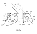
- Fig. 5a shows a schematic view of a plate 501 of another embodiment, in which instead of a cylindrically curved portion, a curved portion 503 is provided with an anticlastic shape.
- the further features of the plate 501 may correspond to those of the plate 101.
- a detail view of the curved portion 503 is shown in FIG Fig. 5b shown. For the sake of clarity, in Fig. 5b some parts of the plate 501 omitted.
- the curved portion 503 has a surface portion 520.
- the surface portion 520 is located on a side of the curved portion 503, which faces away from the curved portion 503 side 106 of the plate 501.
- the surface portion 520 is thus, if the plate 501, as in Fig. 2a, 2b and 5c
- the surface portion 520 may contact the patient's vertebra while the side of the curved portion 503 opposite the surface portion 520 faces away from the bone.
- the surface portion 520 may, in some embodiments, extend across the entire width 108 of the plate 501 in the transverse direction 107. In other embodiments, a beveled or rounded portion may be provided adjacent the surface portion 520 at the edge of the curved portion 503 to make the plate 501 less sharp-edged. In some of these embodiments, the surface area 520 may extend over 90% or more of the width 108.
- reference numeral 512 denotes a point in the surface portion 520.
- the plane of a first main normal section 502 of the surface portion 520 in FIG Point 512 is designated by reference numeral 505.
- the reference numeral 508 denotes the plane of the second main normal section 521 at the point 520.
- the planes 505, 508 pass through the point 512, are perpendicular to each other, and are parallel to a surface normal 522 of the surface section 520 at the point 512.
- the first main normal section 502 is an intersection of the surface section 520 with the plane 505.
- a circle of curvature of the first main normal section 502 at the point 520 with the center 506 and the radius 507 is designated by the reference numeral 504.
- the circle of curvature 504 lies in the plane 505, contacts the first main normal section 502 at the point 520 and has a curvature which is equal to the curvature of the main normal section 502 at the point 520.
- the second main normal section 521 is an intersection curve of the surface section 520 with the plane 508.
- a circle of curvature 511 of the second main normal section 521 at the point 512 lies in the plane 505, contacts the second main normal section 511 at the point 512, has a radius 510 and a center point 509.
- a curvature of the circle of curvature 511 is equal to the curvature of the second main normal section 521 at the point 512.
- the orientation of the planes 505, 508 is selected, in accordance with the mathematical definition of the principal normal sections, such that the radius of curvature 507 is a minimum of the radii of curvature of the intersections of the surface section 520 with all planes passing through the point 512 and parallel to the normal vector 522 , and the radius of curvature 510 is a maximum of all such radii of curvature.
- the radii of curvature of the cut lines are the radii of curvature at point 512.
- the midpoints 506, 509 lie on different sides of the surface portion 520.
- the center point 506 lies on the side of the curved portion 503 facing the curved portion 503 opposite side 106 of the plate 501.
- the center 509 lies on the side of the curved portion facing away from the side 106 of the plate opposite the curved portion 503.
- the surface portion 520 thus has a saddle shape that corresponds to the shape of the edge of the lamina of the human vertebral bone. Thereby, a better adaptation of the shape of the curved portion 503 to the shape of the edge of the lamina of a human vertebral bone can be achieved.
- the surface portion 520 may at least approximately have the shape of a hyperbolic paraboloid. In other embodiments, the surface portion 520 may be at least approximately in the shape of a hyperboloid of revolution. Between the surface portion 520 and the support surface 122 and / or between the surface portion 520 and the protrusions 111, 112 may be a transition region, so that there is a continuous transition between the shape of the surface portion 520 and the shape of the support surface 122 and the shape of the Projections 111, 112 results.
- the normal direction of the plane 505 of the first main normal section 502 with the minimum radius of curvature 507 at the point 512 may be oblique to the longitudinal direction 104 at all points 512 in the surface section 520.
- the average angle of the normal 507 to the plane of the first main normal section 502, wherein the averaging over all points 512 in the surface section 520 is performed may have a value in the range of 95 to 115 degrees, for example a value of 100 degrees.
- the angle between the normal 507 to the plane of the first main normal section 502 and the longitudinal direction 104 at one, several or all points 512 located midway between the longitudinal sides 109, 110 may be in the range of 95 to 115 degrees, for example, a value of 100 degrees.
- the axis of rotation with the longitudinal direction 104 may include an angle in the range of 95 to 115 degrees, for example, an angle of 100 degrees.
- the curved section having a cylindrical curvature described above is the direction of the normal to the plane of the main section having a minimum radius of curvature through a point of the cylindrical surface of the curved section parallel to the direction the curvature axis 117.
- the second main section is obtained in the case of a cylindrical surface an infinite radius of curvature.
- the curved portion 103, 503 may be bent at an angle of approximately 180 degrees to the support portion 102, and the protrusions 111, 112 may be approximately straight so that they lie in a plane approximately parallel to a plane through the Longitudinal direction 104 and the transverse direction 107 is.
- the curved portion 103, 503 may be bent at an angle of less than 180 degrees to the support portion 102, such that the portions 114, 116 of the protrusions facing the curved portion 103, 503 extend to the plane through the longitudinal direction 104 and the transverse direction 107 are inclined.
- the protrusions 111, 112 may be straight so that the entire protrusions 111, 112 are inclined to the plane through the longitudinal direction 104 and the transverse direction 107.
- the portions 114, 116 facing the curved portion 103, 503 may be curved in the same direction as the curved portion 103 or, in the case of an anticlastic shape of the curved portion 503, continue the anticlastic shape of the curved portion 503.
- the curved portion 103, 503 is bent at an angle of approximately 90 degrees to the support portion 102 and the curved portion 103 facing portions 114, 116 are also bent by an angle of approximately 90 degrees to the support portion 102, so that the parts 113, 115 facing away from the curved portion 103 are approximately parallel to the plane through the longitudinal direction 104 and the transverse direction 107.
- the support section 102 may have an extension 119 on one of the longitudinal sides 109, 110, for example the longitudinal side 109.
- the extension 119 may extend along a direction 120 that forms an angle with the longitudinal direction 104, which in FIG Fig. 1b designated by reference numeral 121.
- the angle 121 may have a value less than 90 degrees, so that the extension 119 is oblique to the longitudinal direction 104.
- the extension 119 is thus inclined toward the curved portion 103, 503 and inclined away from the side 106 of the plate 101, which is opposite to the curved portion 103, 503.
- the axis of curvature 117 may extend obliquely to the longitudinal direction 104 and the transverse direction 107.
- the axis of curvature 117 may be inclined toward the extension 119, with the angle 118 between the axis of curvature 117 and the longitudinal direction 104 located on the side of the longitudinal direction 104 remote from the extension 119, as described above, being greater takes as 90 degrees.
- the side 106 of the plate 101, 501 opposite the curved portion 103 may also be inclined toward the extension 119 such that the support portion 102 has a trapezoidal shape.
- the longitudinal side 109, on which the extension 119 is located, is shorter than the projection 119 opposite longitudinal side 110th
- the angle 121 may have a value in the range of 30 to 60 degrees, for example, a value of about 45 degrees.
- the extension 119 is adapted to be suspended in the spinous process of the vertebra of the patient to which the fastener 100 is attached.
- the extension 119 is deformable.
- the appendage 119 may be bent with a tool, such as forceps, into a hook-shaped shape adapted to the individual anatomy of the patient.
- the extension 119 may initially be substantially straight. In other embodiments, the extension 119 may already be hook-shaped in the manufacture of the fastener 100.
- the present invention is not limited to embodiments in which the support portion 102 has an extension 119.
- the extension 119 may be omitted.
- the support portion 102 may have a trapezoidal shape, wherein the axis of curvature 117 and the opposite side 106 include an acute angle, so that one of the two longitudinal sides 109, 110, for example, the longitudinal side 109, is shorter than the other.
- the holding member 124 may have a curved portion 125 similar to the curved portion 103, 503 of the plate 101, 501 and protrusions 126, 127 similar to the protrusions 112, 113. Thereby, the holding member 124 in the lamina of the vortex, on which the fastener 100 is mounted, are hung, and although at an edge of the lamina, which is opposite to that edge on which the curved portion 103, 503 is suspended.
- a portion of the lamina may be suspended after being interposed between the protrusions 126, 127 and a portion of the support member disposed on the opposite side of the curved portion 125 from the protrusions 126, 127 and / or between the protrusions 126, 127 and a part of the support portion 102 near the side 106.
- the fastener When the holding member 124 is connected to the plate 101, 501, e.g. by screwing by means of the screw 129, the fastener can, by the above-described shape of the plate 101, 501 and the holding member 124, obtain a staple-shaped shape suitable for enclosing the lamina of a vertebra. Thereby, a primarily stable attachment of the fastener 100 and connected to the fastener 100 further parts of an implant can be improved. An accidental slipping or slipping out of the fastener 100 from the lamina can be avoided so well.
- the present invention is not limited to embodiments in which the holding member 124 is present.
- the retaining member 124 may be omitted.
- the opening 130 of the plate may also be omitted.
- the opening 130 may be present to facilitate attachment of the retaining member 124 as needed.
- the support surface 122 of the support portion 102 may have a concave shape. Thereby, an adaptation of the shape of the support surface 122 to the anatomical shape of the lamina can be achieved, which allows an enlargement of the contact surface of the fastening element 100 with the lamina.
- Fig. 4 shows a schematic perspective view of a vortex 301.
- the vortex 301 is visible from another perspective.
- an intervertebral disc Between the vertebra 301 and an adjacent vertebra 302 is an intervertebral disc.
- the lamina 310 can be seen.
- the caudal side of vortex 301 is in the Fig. 4 arranged below, the cranial side of the Vertebra 301 above.
- the curvature of the surface of the lamina 310 is schematically represented by curves 401, 402, 403, 404 each extending on the surface of the lamina 301 and lying in a plane intersecting the vortex 301.
- the lamina 310 has, near the cranial edge 408, a region 406 in which the surface of the lamina 310 has a saddle-shaped form. As can be seen in the course of the curves 401 and 402 in the area 406, the surface of the lamina 310 in the direction in which the line 401 extends curved away from the viewer, while in the direction in which the line 402 extends, to the viewer is too curved.
- the lamina 310 has another area 407 in which its surface has a saddle-shaped shape, which can be seen in the course of the curves 401 and 403 in this area.
- region 405 in which the surface of the lamina 310 has a trough-shaped form.
- region 405 both the curve 401 and the curve 404 are curved toward the observer.
- the bearing surface 122 it is possible for the bearing surface 122 to rest on the surface of the lamina 310 both in the region of the depression 405 and in the saddle-shaped regions 406, 407, thereby increasing the contact surface between the fastening element 100 and the lamina 310 can be.
- FIGS. 2a and 2b show the plate 101, 501, wherein the plate 101, 501 in the view of Fig. 2a is shown from the same direction as in the Fig. 1b and in the view of Fig. 2b is shown from the same direction as in the Fig. 1d ,
- the plate 101, 501 in the Fig. 2a and 2b shown in a straightened state.
- the in the Fig. 1a . 1b and 1d shown shape of the plate 101 may from the in the Fig.
- the shape of the flap 501 shown can be obtained by additionally deforming the curved portion 503 such that on the side facing away from the side 106 a "recess" corresponding to the anticlastic shape receives. This can be done for example by hot forming. Alternatively, the anticlastic shape of the curved portion can also be produced by punching.
- the plate 101, 501 may have a width 108 in the range of 7 to 13 mm.
- a width in this area may correspond to the distance between the extensions of the spinous process 312 and the articular process 314, so that the attachment element 100 can be inserted between the articular process 314 and the spinous process 312.
- the width 108 may be adapted to the individual anatomy of the patient and to the vertebra to which the fastener 100 is to be attached. As the size of the vertebrae decreases in the cranial direction, the fastener 100 may have a greater width 108 when it is to be attached to a lumbar vertebra or lower thoracic vertebra than when attached to a vertebra in the upper chest or cervical vertebra should.
- the length 210 may be in the range of 10 to 25 mm, for example, about 22 or about 23 mm.
- the curved portion 103, 503 has a length 202 that can be measured from the beginning of the curved portion 103 on the side of the support portion 102 to the projection of the projections 111, 112.
- the length 202 may be in the range of 3 mm to 7 mm, for example about 5 mm.
- the above with reference to Fig. 5a . 5b described surface portion 520 may occupy 50% or more of the length of the curved portion 503. In the remainder of the curved portion, there may be a transition region in which the anticlastic shape merges into another, for example, cylindrical, curved shape. However, in some embodiments, the surface portion 520 may occupy the entire length of the curved portion 503.
- the curved section does not have to, as in Fig. 2a shown to be bounded by two substantially straight lines.
- the curved Section which is designated in these embodiments by the reference numeral 503 is provided with an anticlastic shape
- the curved portion 503 may be bounded by two straight lines, as in FIG Fig. 2a shown.
- the projections 111, 112 have a length 203 which can be measured from the projection of the respective projection 111, 112 to the tip of the projection 111, 112.
- the length of both projections 111, 112 may be the same.
- the length 203 of the protrusions 111, 112 may be in the range of 3 mm to 10 mm, for example about 5 mm or about 8 mm.
- a greater length 203 of the projections 111, 112 may allow a more stable attachment of the fastener 100 to the lamina. However, because the projections 111, 112 on the implanted fastener 100 are on the side of the lamina 310 facing the patient's spinal cord, the length 203 should be adjusted to maintain a safe distance from the spinal cord to prevent spinal cord injury.
- the projections 111, 112 may have a greater length when the attachment member 100 for suspending the curved portion 103, 503 in the caudal edge 409 is provided as if the fastener 100 is provided for suspending the curved portion 103 in the cranial edge 408.
- the length 203 may be about 5 mm, and the length 203 may be about 8 mm if the curved portion 103 is to be hooked into the caudal edge 409.
- the projections 111, 112 can be formed with truncated edges, for example with rounded edges. This further reduces the risk of injuring the patient's spinal cord upon insertion of the fastener 100.
- the extension 119 may have a length 204 in the range of 17 to 25 mm, for example a length of about 21 mm or about 20 mm and a width 205 in the range of 4 mm to 8 mm, for example a width of about 6 mm.
- a distance 206 between the curved portion 103, 503 side facing the extension 119 and the curved portion 103 may be in the range of about 1 mm to about 3 mm, for example, about 2 mm.
- Reference numeral 255 denotes a plane passing through portions of the support surface 122 adjacent to the curved portion 103, 503 and through portions of the support surface 122 on the side 106 of the plate 101, 501 facing the curved portion 103.
- the plane 255 may extend through the edge of the support surface 122 on the side 106 and through a point of the support surface immediately adjacent to the curved portion 103, 503.
- the support surface 122 Due to the convex shape of the support surface 122 are parts of the support surface not in the plane 255, but are at a distance to the plane.
- the distance of a point on the support surface 122 from the plane can be measured in a direction perpendicular to the plane 255 direction.
- the support surface 122 includes one or more points spaced from the plane 255 that is greater than or equal to the distance of all other points of the support surface 122 from the plane 255.
- the distance of these points from the plane 255 will hereinafter be referred to as "maximum distance", and the points located at the maximum distance from the plane 255 will be referred to as "points of maximum distance”.
- Reference numeral 250 denotes a substantially flat portion of the support surface 122 which is substantially parallel to the plane 255.
- the portion 255 may be circular with a diameter 254.
- the diameter 254 may have a value in the range of 3 mm to 6 mm, for example a value of approximately 4 mm. Points on the support surface in part 250 are at a distance 257 from plane 255.
- the flat part 250 of the support surface 122 may be surrounded by a part 251 having a substantially conical shape. Points in the conical part 251 of Pad 122 are spaced apart from plane 255 which is less than the spacing of the dots in flat portion 250 of pad 122 from plane 255. Thus, the flat portion 250 of the support surface 122 forms a set of points maximum distance from the plane 255.
- the bearing surface 122 can lie substantially in the plane 255, so that the bearing surface in the vicinity of the corners formed by the sides 105, 106 and the longitudinal sides 109, 110 is substantially flat. In the middle of the sides 105, 106, the conical region 122 can extend to the edge of the support section 102 and intersect the plane 255 there.
- the conical part 251 of the support surface 122 does not have to, as in Fig. 2b shown extending from the edge of the flat portion 250 to the edge of the support portion 102 on the sides 105, 106 of the plate 101, 501.
- the conical portion 251 may annularly enclose the flat portion 250. Outside the conical part 251, the support surface 122 may lie substantially in the plane 255.
- the flat portion 250 and the conical portion 251 may at least partially rest in the trough-shaped area 405 of the lamina 310. Thereby, the contact area between the lamina 310 and the plate 101 can be increased.
- the at least partial support of the flat part 250 and / or the conical part can be achieved with constant dimensions in a certain range of dimensions of the vortex, so that the same fastening elements 100 can be used on different sized vertebrae. It is therefore possible to provide a plurality of differently dimensioned vertebrae with a relatively small selection of differently dimensioned fasteners, thereby enabling economical production of the fasteners.
- the present invention is not limited to embodiments in which the bearing surface 122 has the shape described above.
- the support surface 122 may at least partially have a spherical, hyperboloidal, paraboloidal or ellipsoidal shape.
- the distance 257 of the maximum distance points from the plane 255 may have a value in the range of 1 mm to 2 mm, for example, a value of about 1.5 mm.
- a distance between the center of the flat portion 250 and the side 106 may have a value in the range of about 7 to about 11 mm, for example, a value of about 8 mm or about 10 mm.
- the connector 131 may be disposed opposite at least one of the maximum distance points from the plane 255.
- the holding member 130 may be disposed opposite to the flat portion 250 of the support surface 122.
- the top surface 123 may also have a convex shape.
- the top surface 123 may have one or more maximum distance points from a plane 256 that extends through portions of the top surface 123 adjacent to the curved portion 103 and through portions of the top surface 123 on the side 106 that faces the curved portion 103, 503.
- the maximum distance points may have a distance 258 in the range of 3 to 5 mm, for example a distance of approximately 4 mm, from the plane 256.
- the top surface 123 may include a substantially flat portion 252 that is parallel to the plane 256 and spaced therefrom 258, and a generally tapered portion 253 that surrounds the portion 252.
- the flat part 252 of the top surface 123 may be opposite to the flat part 250 of the support surface 122.
- the diameter of the flat parts 250, 252 may be approximately equal.
- the holding member 130 may be disposed in the flat part 252 so as to be connected to a maximum thickness portion of the plate. Thereby, the rigidity of the fastener 100 can be improved.
- An spinal deformity correction implant according to the present invention may comprise two or more fasteners having the features of the fastener 100 described above.
- the shape of the fasteners can be adjusted depending on the nature of the attachment of the implant to the spinal column of the patient.
- the shape of the fastener 100 may differ depending on whether it is for hooking the curved portion 103, 503 into the cranial (upper) edge 408 the lamina 310 or for hanging the curved portion 103, 503 in the caudale (lower) edge 409 of the lamina 310 is designed.
- the caudal edge fastener may have a greater width 108 than the cranial edge fastener.
- the caudal edge fastener may have a width of 10 or 12 mm, and the crain edge fastener may have a width of 8 or 10 mm.
- the protrusions 111, 112 of the caudal edge fastener may have a greater length.
- the cranial edge fastener may be formed with the appendage 119 for attachment to the spinous process of the patient's vertebra, while in the caudal edge fastener, the appendage 119 may be omitted.
- different fasteners may be provided for attachment to the left or right lamina, with the left side fasteners being mirror symmetric to those for the right side.
- the shorter longitudinal side 109 and the extension 119 are attached adjacent the spinous process of the vertebra.
- the longer side 110 is then next to one of the transverse processes of the vortex.
- Fig. 3a shows a schematic representation of a portion of a spine 300 of a patient.
- Fig. 3a shows the caudal direction to the right and the cranial direction points to the left.
- Spine 300 includes vertebrae 301, 302, 303, 304, 305, between which intervertebral discs 306, 307, 308, 309 are located.
- the vertebra 301 comprises a vertebral body 311, a spinous process 312 and transverse processes 313, 314. Between the transverse process 313 and the spinous process 312 is a lamina 310. Another lamina is located between the spinous process 312 and the transverse process 314.
- the shape of the lamina 310 was referring to above Fig. 4 explained in more detail.
- the vertebrae 302 to 305 have a similar shape as the vertebra 301, but are slightly larger because they are further caudal.
- the portion of the spine 300 that is to be corrected and / or stabilized with the aid of the implant for example the vertebrae 301 to 304, is exposed. This can be done with the aid of the techniques known to those skilled in the art.
- Fig. 3b shows the in Fig. 3a shown portion of the spine 300 at a later stage of implantation.
- a plate 101a of a first fastening element 100a is mounted on the lamina 310 of the vertebra 301 , which is connected to a first connecting element 131a.
- Attached to the lamina of the vortex 304 is the plate 101b of a second fastener 100b of the present invention connected to a second connector 131b.
- the fasteners 100a, 100b may have features corresponding to those described above with respect to FIGS Fig. 1a to 1d . 2a, 2b and 5a, 5b have been described.
- the plates 101a, 101b may have the features of the above with reference to FIG Fig. 1a to 1d described plate 101, or the features of the above with reference to Fig. 5a . 5b have described plate 501.
- the curved portions indicated by the reference numerals 103a, 103b may be cylindrically curved portions or anticlastic curved portions.
- the curved portion 103a of the plate 101a of the first attachment member 100a is hung in the cranial edge of the lamina 310 of the vertebra 301, and the curved portion 103b of the plate 101b of the second attachment member 100b is hung in the caudal edge of the lamina of the vertebra 304.
- a severing of the yellow band is not required. Instead, the protrusions of the fasteners 100a, 100b (in FIG Fig. 3b not visible) are clamped in the yellow band.
- the curved portions 103a, 103b may be sandwiched between the base of the spinous processes of the vertebrae 301, 304 and the medial edge of the articular processes of the vertebrae 302, 304.
- the first fastening element 100a has an extension 119a, which is suspended in the spinous process 312 of the vertebra 301.
- the Extension 119a initially be substantially straight (as in Fig. 1a to 2b shown) and are brought into a hook-shaped form during the operation by bending with the help of a pair of pliers. Thereby, an adaptation of the shape of the extension 119 to the individual anatomy of the patient can be achieved.
- the second fastener 100b does not include any extension in this embodiment.
- Fig. 3c shows the spine 300 at a later stage of implantation.
- a retaining element 124a of the first fastening element is hooked into the caudal edge of the lamina 310 of the vertebra 301 and connected by a screw 129a to the plate 101a of the first fastening element 100a.
- a holding element 124b is suspended in the cranial edge of the lamina of the vertebra 304 and connected by means of a screw 129b with the plate 101b of the second fastening element.
- one or both of the support members 124a, 124b may be omitted.
- the retaining members 124a, 124b may also be used as needed when the degree of primary stability achieved without the retaining members 124a, 124b is considered insufficient.
- the holding members 124a, 124b may be omitted.
- the correcting and stabilizing function of the fastening elements 100a, 100b can also be achieved without the holding plates 124a, 124b, while the holding elements 124a, 124b can be used as aids for intraoperative manipulation.
- Fig. 3d shows the spine 300 in a further stage of implantation.
- the spine 300 is aligned by moving the patient to a desired position.
- the portion of the spine 300 between the vertebrae 301 and 304 by inserting a connecting rod 380 in the connecting elements 130a, 130b and fixing the connecting rod 380 in the connecting elements 130a, 130b, for example by means of screws 381, 382, in the thread of the Connecting elements 130a, 130b are screwed, stabilized in the desired position and fixed.
- the retaining elements 124a, 124b may be removed after fixing the connecting rod 380. In other embodiments, however, they may remain in the body of the patient.
Abstract
Description
Die vorliegende Erfindung bezieht sich auf Befestigungselemente zum Befestigen eines Implantats zur Korrektur einer Wirbelsäulendeformität an einer Lamina eines Wirbels, sowie auf ein Implantat zur Korrektur einer Wirbelsäulendeformität.The present invention relates to fasteners for securing an implant for correcting spinal deformity to a lamina of a vertebra, and to an implant for correcting spinal deformity.
Im Lauf des Lebens verändert sich der Knochen eines Menschen. Mit zunehmendem Alter tritt ein Verlust an Knochensubstanz auf, der mit einer Verminderung der Knochendichte einhergeht. Bei manchen Patienten tritt eine Osteoporose auf. Dabei handelt es sich um einen pathologischen Knochenschwund, der den organischen und den Mineralanteil des Knochens gleichzeitig betrifft. Dadurch bedingt können die Knochen instabil werden, und es können Deformationen von Knochen auftreten. Die degenerative Instabilität und/oder Deformation der Knochen kann insbesondere die Wirbelsäule des Patienten betreffen, in der es zu osteoporotischen Wirbelfrakturen, sogenannten Sinterungsbrüchen, kommen kann.In the course of life, the bones of a human are changing. With increasing age, a loss of bone substance occurs, accompanied by a decrease in bone density. Some patients have osteoporosis. This is a pathological bone loss that simultaneously affects the organic and mineral parts of the bone. As a result, the bones can become unstable and bone deformities can occur. The degenerative instability and / or deformation of the bones can in particular affect the spinal column of the patient, in which osteoporotic vertebral fractures, so-called sintering fractures, can occur.
Eine nicht behandelte Instabilität und/oder Deformation der Wirbelsäule kann im Lauf der Zeit zum Verlust der Gehfähigkeit und damit zur Pflegebedürftigkeit des Patienten führen. Konservative Behandlungsmethoden wie zum Beispiel ein Korsett, physikalische Therapie und/oder eine Schmerztherapie haben sich bei älteren Patienten als nur begrenzt erfolgreich erwiesen.Untreated instability and / or deformation of the spine can, over time, result in loss of ambulation and hence patient care. Conservative treatments such as corsetry, physical therapy and / or pain therapy have proven to be less successful in older patients.
Es wurde deshalb vorgeschlagen, die degenerative Instabilität und/oder Deformität der Wirbelsäule durch eine Vertebroplastie oder eine Kyphoplastie zu behandeln. Bei der Vertebroplastie wird unter Lokalanästhesie eine Hohlnadel durch die Bogenwurzeln eines von osteoporotischen Frakturen betroffenen Wirbels eingebracht. Anschließend spritzt man Knochenzement in den Wirbelkörper ein, der unter Hitzeentwicklung in kurzer Zeit aushärtet. Die Kyphoplastie ist eine Variante der Vertebroplastie, bei der vor dem Einbringen von Knochenzement die Deformation des Wirbels durch Aufpumpen eines Ballons im Wirbelkörper beseitigt oder zumindest verringert wird.It has therefore been proposed to treat the degenerative instability and / or deformity of the spine by vertebroplasty or kyphoplasty. In vertebroplasty, under local anesthesia, a hollow needle is inserted through the arch roots of a vertebra affected by osteoporotic fractures. Subsequently, one injects bone cement into the vertebral body, which cures under heat in a short time. Kyphoplasty is a variant of vertebroplasty in which, prior to the introduction of bone cement, the deformation of the vertebra is eliminated or at least reduced by inflating a balloon in the vertebral body.
Da die Vertebroplastie und die Kyphoplastie minimal invasive Verfahren sind, eignen sie sich gut für ältere Patienten. Degenerative Instabilitäten und/oder Deformitäten können mit ihnen allerdings nicht vollständig behoben werden.Because vertebroplasty and kyphoplasty are minimally invasive procedures, they are well suited to older patients. Degenerative instabilities and / or deformities can not be fully remedied with them.
Es ist bekannt, Deformationen der Wirbelsäule wie zum Beispiel eine Skoliose und/oder eine Kyphose durch Einsetzen vom Implantaten zu behandeln. Dabei werden Wirbel des Patienten zuerst durch Bewegen des Patienten in einer gewünschten Stellung ausgerichtet. Anschließend werden die Wirbel durch das Implantat fest miteinander verbunden und so in der gewünschten Stellung fixiert.It is known to treat deformities of the spine such as scoliosis and / or kyphosis by inserting it from the implant. This will be vortex of Patients first aligned by moving the patient to a desired position. Subsequently, the vertebrae are firmly connected to one another by the implant and thus fixed in the desired position.
Die Befestigung des Implantats an den Wirbeln kann mit Hilfe von Pedikelschrauben oder Laminahaken erfolgen. Derartige Befestigungsmittel sind in
Weitere Befestigungssysteme nach dem Stand der Technik sind beispielsweise in den Druckschriften
Die bekannten Implantate zur Behandlung von Deformationen eignen sich jedoch nur begrenzt für die Behandlung älterer Patienten. Besonders in Fällen einer schweren Form der Osteopenie mit einem T-Score von unter -1,5 der Normalabweichung des Knochenmineralgehalts (BMD), sowie bei allen Formen der Osteoporose, ermöglichen die zur Verfügung stehenden Implantate keine ausreichende Stabilisierung oder korrigierende Aufrichtung der Wirbelsäule.However, the known implants for the treatment of deformations are only limitedly suitable for the treatment of elderly patients. Especially in cases of a severe form of osteopenia with a T-score of less than -1.5 the normal deviation of bone mineral content (BMD), as well as in all forms of osteoporosis, the available implants do not allow sufficient stabilization or corrective erection of the spine.
Ein Nachteil bekannter Implantate ist, dass an den Kontaktflächen zwischen den Knochen und dem Implantat ein relativ großer Druck auftreten kann. Die Druckbelastung auf Knochen, bei denen bereits ein gewisser Verlust an Knochensubstanz aufgetreten ist, kann an der Kontaktfläche Mikrofrakturen verursachen, die im weiteren Verlauf zur Destabilisierung des Implantats führen können.A disadvantage of known implants is that a relatively large pressure can occur at the contact surfaces between the bone and the implant. The pressure on bone, which has already suffered some loss of bone, may cause microfractures at the contact surface, which may subsequently lead to destabilization of the implant.
Ein weiterer Nachteil bekannter Implantate ist, dass die Implantate während interoperativer Manipulationen wie dem Verbinden der Laminahaken oder Pedikelschrauben mit dem Metallstab sowie bei der Korrektur der Deformität mit einem Distraktions- Kompressions- oder Derotationsmanöver eine gewisse Instabilität aufweisen können. Die kann zum Verrutschen des Implantats führen, was die Operation erschweren und ihre Dauer verlängern kann.Another disadvantage of known implants is that the implants have some instability during interoperative manipulations, such as connecting the laminating hooks or pedicle screws to the metal rod, and correcting the deformity with a distraction compression or derotation maneuver can have. This can lead to slipping of the implant, which can complicate the operation and prolong its duration.
Noch ein weiterer Nachteil bekannter Implantate ist die Rigidität vorhandener Systeme, die keine oder eine sehr geringe Beweglichkeit des Knochens relativ zum Implantat erlaubt. Dadurch können relativ große mechanische Belastungen der Kontaktfläche zwischen dem Knochen und dem Implantat auftreten, die zur Überlastung der Kontaktfläche führen können. Derartige Komplikationen können insbesondere während des Heilungsprozesses kurz nach der Operation auftreten.Yet another disadvantage of known implants is the rigidity of existing systems that allows little or no bone mobility relative to the implant. As a result, relatively large mechanical stresses on the contact surface between the bone and the implant can occur, which can lead to overloading of the contact surface. Such complications may occur especially during the healing process shortly after surgery.
Ein weiterer Nachteil bekannter Implantate ist, dass zum Anbringen bekannter Laminahaken das gelbe Band (Ligamentum flavum), das sich zwischen jeweils zwei Wirbeln befindet und die Wirbelsäule stabilisiert, entfernt werden muss, was zu einer Verringerung der Stabilität der Wirbelsäule führen kann.A further disadvantage of known implants is that the yellow band (ligamentum flavum), which is located between every two vertebrae and stabilizes the spinal column, must be removed for attaching known laminating hooks, which can lead to a reduction in the stability of the spinal column.
Es ist eine Aufgabe der vorliegenden Erfindung, ein Befestigungselement zum Befestigen eines Implantats zur Korrektur einer Wirbelsäulendeformität sowie ein Implantat bereitzustellen, das eine Verringerung der Druckbelastung an den Kontaktflächen zwischen dem Knochen und dem Implantat ermöglicht.It is an object of the present invention to provide a fastener for securing an implant for correcting spinal deformity and an implant that enables a reduction in the pressure load on the contact surfaces between the bone and the implant.
Es ist eine weitere Aufgabe der vorliegenden Erfindung, ein Befestigungselement zum Befestigen eines Implantats zur Korrektur einer Wirbelsäulendeformität sowie ein Implantat bereitzustellen, das eine primäre Stabilität aufweist und so eine Vereinfachung der intraoperativen Manipulationen ermöglicht.It is a further object of the present invention to provide a fastener for securing an implant for correcting spinal deformity and an implant having primary stability, thus enabling simplification of intraoperative manipulations.
Noch eine weitere Aufgabe der vorliegenden Erfindung ist, ein Befestigungselement zum Befestigen eines Implantats zur Korrektur einer Wirbelsäulendeformität sowie ein Implantat bereitzustellen, das eine gewisse Beweglichkeit des Implantats relativ zum Knochen ermöglicht.Yet another object of the present invention is to provide a fastener for securing an implant for correcting spinal deformity, and an implant that allows for some mobility of the implant relative to the bone.
Noch eine weitere Aufgabe der vorliegenden Erfindung ist, ein Befestigungselement zum Befestigen eines Implantats zur Korrektur einer Wirbelsäulendeformität sowie ein Implantat bereitzustellen, bei dem das Entfernen des gelben Bandes vermieden werden kann.Yet another object of the present invention is to provide a fastener for securing an implant for correcting spinal deformity and an implant in which removal of the yellow band can be avoided.
Ein Befestigungselement zum Befestigen eines Implantats zur Korrektur einer Wirbelsäulendeformität an einer Lamina eines Wirbels gemäß einem Aspekt der Erfindung umfasst eine Platte mit einem Auflageabschnitt zur Auflage auf der Lamina.A fastener for securing an implant for correcting spinal deformity on a lamina of a vertebra according to an aspect of the invention comprises a plate having a support portion for resting on the lamina.
Die Platte weist an einer Seite einen gekrümmten Abschnitt zum Einhängen der Platte in die Lamina auf. Eine Längsrichtung der Platte verläuft von der Seite mit dem gekrümmten Abschnitt zu einer Seite der Platte, die der Seite mit dem gekrümmten Abschnitt gegenüberliegt. Eine Querrichtung der Platte verläuft senkrecht zu der Längsrichtung. Die Platte weist in der Querrichtung eine Breite von 7 mm bis 13 mm auf.The plate has on one side a curved portion for mounting the plate in the lamina. A longitudinal direction of the plate extends from the side having the curved portion to one side of the plate opposite to the side having the curved portion. A transverse direction of the plate is perpendicular to the longitudinal direction. The plate has a width of 7 mm to 13 mm in the transverse direction.
Durch die im Vergleich zu bekannten Laminahaken größere Breite des Implantats kann die Kontaktfläche zwischen dem Befestigungselement und dem Knochen, auf der der Auflageabschnitt aufliegt, vergrößert werden. Dadurch können mechanische Belastungen des Knochens im Bereich der Kontaktfläche verringert werden. Da die Platte, anders als beispielsweise ein Pedikelhaken, nicht starr mit dem Knochen verbunden wird, ist eine Beweglichkeit des Befestigungselements sowie des Implantats, das mit Hilfe des Befestigungselements angebracht wird, relativ zum Knochen in gewissem Umfang möglich. Dadurch kann ein semirigides System bereitgestellt werden, was ebenfalls eine Verringerung der Belastung der Kontaktfläche zwischen dem Knochen und dem Befestigungselement ermöglicht. Die Breite der Platte im Bereich von 7 bis 13 mm ermöglicht es ferner, den gekrümmten Abschnitt während der Operation zwischen der Basis des Dornfortsatzes und der medialen Kante des Gelenkfortsatzes einzuklemmen, wodurch eine primäre Stabilität des Befestigungselements während der Operation bereitgestellt werden kann.Due to the greater width of the implant compared to known lamination hooks, the contact surface between the fastening element and the bone on which the support section rests can be increased. As a result, mechanical loads on the bone in the area of the contact surface can be reduced. Since the plate, unlike, for example, a pedicle hook, is not rigidly connected to the bone, a mobility of the fastener and the implant, which is attached by means of the fastener, relative to the bone to some extent possible. Thereby, a semirigid system can be provided, which also allows a reduction of the load on the contact surface between the bone and the fastener. The width of the plate in the range of 7 to 13 mm also allows the curved portion to be clamped between the base of the spinous process and the medial edge of the articular process during surgery, thereby providing primary stability of the fastener during the operation.
Geeigneterweise weist das Befestigungselement zwei Längsseiten auf, die parallel zu der Längsrichtung der Platte sind.Suitably, the fastener has two longitudinal sides which are parallel to the longitudinal direction of the plate.
Geeigneterweise weist das Befestigungselement zwei oder mehr, beispielsweise drei oder mehr, Vorsprünge auf, die sich an den gekrümmten Abschnitt anschließen. Jeder Vorsprung weist einen vom gekrümmten Abschnitt der Platte abgewandten Teil auf, der gegenüber dem Auflageabschnitt der Platte angeordnet ist.Suitably, the fastening element has two or more, for example three or more, projections which adjoin the curved section. Each projection has a portion facing away from the curved portion of the plate, which is arranged opposite to the support portion of the plate.
Das Befestigungselement kann in solchen Ausführungsformen derart in die Lamina eingehängt werden, dass sich die Vorsprünge in das gelbe Band einklemmen. So kann das Befestigungselement auch ohne eine Durchtrennung des gelben Bandes an der Lamina angebracht werden. Dies ermöglicht einen besseren Schutz des Bewegungssegments, das durch den Wirbel, an dem das Befestigungselement angebracht wird und einem benachbarten Wirbel, der durch das gelbe Band mit diesem verbunden ist, gebildet wird. Die Vorsprünge können außerdem ein Abrutschen des Befestigungselements von der Kante der Lamina, in die der gekrümmte Abschnitt eingehängt wird, verhindern. Dadurch wird die Stabilität des Befestigungselements verbessert.In such embodiments, the fastening element can be suspended in the lamina in such a way that the projections pinch into the yellow band. Thus, the fastener can be attached to the lamina without a separation of the yellow tape. This allows better protection of the segment of motion formed by the vertebra to which the fastener is attached and an adjacent vertebra connected to it by the yellow band. The protrusions may also cause the fastener to slip off the edge of the lamina, into which the curved portion is hung. As a result, the stability of the fastener is improved.
Ein Befestigungselement zum Befestigen eines Implantats zur Korrektur einer Wirbelsäulendeformität an einer Lamina eines Wirbels gemäß einem weiteren Aspekt der Erfindung umfasst eine Platte, die an einer Seite einen gekrümmten Abschnitt zum Einhängen der Platte in die Lamina aufweist. An den gekrümmten Abschnitt schließen sich zwei oder mehr, beispielsweise drei oder mehr Vorsprünge an. Jeder Vorsprung weist einen vom gekrümmten Abschnitt der Platte abgewandten Teil auf, der gegenüber einem Auflageabschnitt der Platte angeordnet ist. Der Auflageabschnitt befindet sich zwischen dem gekrümmten Abschnitt und einer Seite der Platte, die der Seite mit dem gekrümmten Abschnitt gegenüberliegt.A fastener for securing an implant for correcting spinal deformity on a lamina of a vertebra according to another aspect of the invention comprises a plate having on one side a curved portion for mounting the plate in the lamina. The curved portion is followed by two or more, for example, three or more protrusions. Each projection has a portion facing away from the curved portion of the plate, which is arranged opposite a support portion of the plate. The rest portion is located between the curved portion and a side of the plate opposite to the side with the curved portion.
Durch die Plattenform des Befestigungselements kann eine relativ große Kontaktfläche zwischen dem Knochen des Patienten und dem Befestigungselement bereitgestellt werden, die eine Verringerung der mechanischen Druckbelastung der Kontaktfläche ermöglicht. Nach dem Einhängen des gekrümmten Abschnitts in die Lamina bleibt eine gewisse Beweglichkeit des Befestigungselements relativ zum Knochen erhalten, so dass ein semirigides System bereit gestellt wird. Dadurch können Überbelastungen der Kontaktfläche zwischen dem Implantat und dem Knochen, die bei einem rigiden System auftreten könnten, vermieden werden. Die Vorsprünge können dabei helfen, ein Abrutschen des Befestigungselements von der Lamina, in die es eingehängt wird, zu vermeiden. Außerdem können die Vorsprünge in das gelbe Band eingeklemmt werden.Due to the plate shape of the fastener, a relatively large contact area between the patient's bone and the fastener can be provided, which allows a reduction of the mechanical pressure loading of the contact surface. After attaching the curved portion in the lamina some mobility of the fastener is maintained relative to the bone, so that a semirigid system is provided. As a result, overloading of the contact surface between the implant and the bone, which could occur in a rigid system, can be avoided. The projections can help to prevent slippage of the fastener from the lamina, in which it is hung. In addition, the projections can be clamped in the yellow band.
Geeigneterweise weist der Auflageabschnitt zwei Längsseiten auf, die parallel zu einer Längsrichtung der Platte sind. Die Längsrichtung verläuft von der Seite mit dem gekrümmten Abschnitt zu der Seite der Platte, die der Seite mit dem gekrümmten Abschnitt gegenüberliegt.Suitably, the support portion has two longitudinal sides which are parallel to a longitudinal direction of the plate. The longitudinal direction extends from the side having the curved portion to the side of the plate opposite to the side having the curved portion.
Geeigneterweise haben die Längsseiten einen Abstand im Bereich von 7 mm bis 13 mm.Suitably, the longitudinal sides have a spacing in the range of 7 mm to 13 mm.
Geeigneterweise verläuft eine Krümmungsachse des gekrümmten Abschnitts der Platte schräg zu der Längsrichtung. Geeigneterweise schließt die Krümmungsachse mit der Längsrichtung einen Winkel im Bereich von 95 bis 115 Grad ein. Dadurch kann eine verbesserte Anpassung der Form des Befestigungselements an die Form der Lamina erzielt werden.Suitably, a curvature axis of the curved portion of the plate is oblique to the longitudinal direction. Suitably, the axis of curvature includes an angle in the range of 95 to 115 degrees with the longitudinal direction. Thereby, an improved adaptation of the shape of the fastener to the shape of the lamina can be achieved.
Geeigneterweise weist der gekrümmte Abschnitt einen Oberflächenabschnitt auf, welcher der dem gekrümmten Abschnitt gegenüberliegenden Seite der Platte zugewandt ist, wobei für jeden Punkt in dem Oberflächenabschnitt gilt, dass ein Hauptnormalschnitt des Oberflächenabschnitts in dem Punkt in einer Ebene liegt, deren Normale schräg zu der Längsrichtung ist. Der gekrümmte Abschnitt kann dabei eine zylindrische Krümmung aufweisen, wobei eine Krümmungsachse des gekrümmten Abschnitts der Platte schräg zu der Längsrichtung verläuft. Beispielsweise kann die Krümmungsachse mit der Längsrichtung einen Winkel im Bereich von 95 bis 115 Grad einschließen. Alternativ dazu kann der Oberflächenabschnitt eine antiklastische Fläche sein, wobei der Mittelpunkt des zu dem genannten Hauptnormalschnitts gehörigen Krümmungskreises auf der Seite des gekrümmten Abschnitts liegt, die der dem gekrümmten Abschnitt gegenüberliegenden Seite der Platte zugewandt ist.Conveniently, the curved portion has a surface portion facing the side of the plate opposite the curved portion, wherein for each point in the surface portion, a main normal section of the surface portion lies in the point in a plane whose normal is oblique to the longitudinal direction , The curved portion may have a cylindrical curvature, wherein a curvature axis of the curved portion of the plate extends obliquely to the longitudinal direction. For example, the axis of curvature may include an angle in the range of 95 to 115 degrees with the longitudinal direction. Alternatively, the surface portion may be an anticlastic surface, the center of the circle of curvature associated with said main normal section being on the side of the curved portion facing the side of the plate opposite the curved portion.
Eine antiklastische Form des gekrümmten Abschnitts ermöglicht eine bessere Anpassung der Form des Befestigungselements an die Form der menschlichen Laminakante, so dass der gekrümmte Abschnitt auf einer größeren Fläche auf der Laminakante aufliegt. Dadurch kann die mechanische Belastung des Kochens verringert und der Halt des Befestigungselements am Knochen verbessert werden. Eine zylindrische Form des gekrümmten Abschnitts hat den Vorteil einer im Vergleich zu einer antiklastischen Form einfacheren Herstellung.An anticlastic shape of the curved portion allows for better conforming of the shape of the fastener to the shape of the human laminar edge so that the curved portion rests on a larger surface on the laminar edge. This can reduce the mechanical stress of cooking and improve the retention of the fastener on the bone. A cylindrical shape of the curved portion has the advantage of simpler manufacture compared to an anticlastic shape.
Der genannte Hauptnormalschnitt kann der Hauptnormalschnitt mit minimalem Krümmungsradius sein.The mentioned main normal section may be the main normal section with minimum radius of curvature.
In Ausführungsformen, in denen der gekrümmte Abschnitt eine zylindrische Krümmung aufweist, kann die Normale zur Ebene des Hauptnormalschnitts parallel zur Zylinderachse sein.In embodiments in which the curved portion has a cylindrical curvature, the normal to the plane of the main normal section may be parallel to the cylinder axis.
Geeigneterweise weist der Auflageabschnitt an einer der beiden Längsseiten einen Fortsatz auf, der sich in einer zur Längsrichtung der Platte schrägen Richtung erstreckt. Der Fortsatz kann zur Abstützung des Befestigungselements am Dornfortsatz des Wirbels, in dessen Lamina das Befestigungselement eingehängt wird, verwendet werden. Dadurch kann die primäre Rotationsstabilität des Befestigungselements verbessert werden.Suitably, the support portion on one of the two longitudinal sides on an extension which extends in an oblique to the longitudinal direction of the plate direction. The extension can be used to support the fastener on the spinous process of the vertebra, in whose lamina the fastener is mounted. Thereby, the primary rotational stability of the fastener can be improved.
Geeigneterweise ist der Fortsatz verformbar ausgebildet. So kann der Fortsatz während der Operation an die individuelle Anatomie des Patienten angepasst werden, beispielsweise durch Biegen des Fortsatzes mit Hilfe einer Zange.Suitably, the extension is formed deformable. Thus, the extension can be adapted during surgery to the individual anatomy of the patient, for example by bending the extension using a pair of pliers.
Geeigneterweise weist der Auflageabschnitt eine konvexe Auflagefläche auf, wobei der gekrümmte Abschnitt zu der Auflagefläche hin gekrümmt ist. Die Lamina menschlicher Wirbelknochen hat eine sattelförmige Oberfläche, in deren Mitte sich eine Mulde befindet. Durch die konvexe Auflagefläche kann erreicht werden, dass die Auflagefläche des Auflageabschnitts sowohl in der Nähe der Seite des Befestigungselements mit dem gekrümmten Abschnitt und der gegenüberliegenden Seite des Befestigungselements, als auch in der Mitte der Lamina auf der Oberfläche der Lamina aufliegt. Dadurch kann eine Vergrößerung der Kontaktfläche zwischen dem Auflageabschnitt und der Lamina erzielt werden, die eine Verringerung mechanischer Belastungen des Knochens ermöglicht.Conveniently, the support portion has a convex bearing surface, the curved portion being curved toward the bearing surface. The lamina of human vertebral bones has a saddle-shaped surface in the center of which is a trough. By the convex bearing surface can be achieved that the bearing surface of the support portion rests both near the side of the fastener with the curved portion and the opposite side of the fastener, as well as in the middle of the lamina on the surface of the lamina. As a result, an enlargement of the contact surface between the support section and the lamina can be achieved, which enables a reduction in mechanical stress on the bone.
Geeigneterweise weist die Auflagefläche mindestens einen Punkt maximalen Abstands zu einer Ebene auf. Die Ebene verläuft durch Bereiche der Auflagefläche neben dem gekrümmten Abschnitt und durch Bereiche der Auflagefläche auf der Seite der Platte, die der Seite mit dem gekrümmten Abschnitt gegenüberliegt. Der mindestens eine Punkt maximalen Abstands hat von der Ebene einen Abstand im Bereich von 1 bis 2 mm. Eine derartige Geometrie der Auflagefläche ist der Form der Lamina besonders gut angepasst.Suitably, the bearing surface has at least one point of maximum distance from a plane. The plane passes through portions of the support surface adjacent to the curved portion and through portions of the support surface on the side of the plate opposite the curved portion side. The at least one point of maximum distance has a distance from the plane in the range of 1 to 2 mm. Such a geometry of the support surface is particularly well adapted to the shape of the lamina.
Geeigneterweise hat zumindest ein Teil der Auflagefläche eine konische Form. Eine zumindest teilweise konische Form ermöglicht eine große Kontaktfläche zwischen dem Befestigungselement und der Lamina.Suitably, at least a part of the support surface has a conical shape. An at least partially conical shape allows a large contact surface between the fastener and the lamina.
Geeigneterweise weist der Auflageabschnitt eine konvexe Deckfläche auf, wobei der gekrümmte Abschnitt von der Deckfläche weg gekrümmt ist.Suitably, the support portion has a convex top surface, the curved portion being curved away from the top surface.
Geeigneterweise weist die Deckfläche mindestens einen Punkt maximalen Abstands zu einer Ebene auf. Die Ebene verläuft durch Bereiche der Deckfläche neben dem gekrümmten Abschnitt und durch Bereiche der Deckfläche auf der Seite der Platte, die der Seite mit dem gekrümmten Abschnitt gegenüberliegt. Der mindestens eine Punkt maximalen Abstands hat von der Deckfläche einen Abstand im Bereich von 3 bis 5 mm.Suitably, the top surface has at least one point of maximum distance to a plane. The plane passes through portions of the top surface adjacent to the curved portion and through portions of the top surface on the side of the plate opposite the side with the curved portion. The at least one point maximum distance has a distance in the range of 3 to 5 mm from the top surface.
Geeigneterweise hat zumindest ein Teil der Deckfläche eine konische Form.Suitably, at least a part of the top surface has a conical shape.
Geeigneterweise umfasst das Befestigungselement ferner ein Haltelement. Das Haltelement weist einen gekrümmten Abschnitt zum Einhängen des Haltelements in die Lamina auf. Es ist derart an dem Befestigungselement anbringbar, dass der gekrümmte Abschnitt des Haltelements dem gekrümmten Abschnitt des Befestigungselements gegenüber angeordnet ist.Suitably, the fastening element further comprises a retaining element. The holding element has a curved section for hooking the holding element into the lamina. It can be attached to the fastening element such that the curved section of the retaining element is arranged opposite the curved section of the fastening element.
Nach dem Einhängen des gekrümmten Abschnitts des Befestigungselements in eine Kante der Lamina ist die zweite Kante, die der Kante, in die der gekrümmte Abschnitt eingehängt wird, gegenüberliegt, noch frei. Der gekrümmte Abschnitt des Halteelements kann in die zweite Kante eingehängt werden und anschließend mit dem Befestigungselement verbunden werden. Dadurch kann das Befestigungselement primär stabil mit der Lamina verbunden werden, wodurch ein Verrutschen des Befestigungselements im weiteren Verlauf der Operation vermieden werden kann. Die Primärstabilität des mit dem Halteelement verbundenen Befestigungselements kann dabei die einer Pedikelschraube erreichen.After hanging the curved portion of the fastener into an edge of the lamina, the second edge, which is opposite to the edge, in which the curved portion is hooked, still free. The curved portion of the retaining element can be hung in the second edge and then connected to the fastener. As a result, the fastening element can be connected to the lamina in a primarily stable manner, as a result of which slippage of the fastening element in the course of the operation can be avoided. The primary stability of the fastening element connected to the holding element can reach that of a pedicle screw.
Ein Implantat zur Korrektur einer Wirbelsäulendeformität gemäß der vorliegenden Erfindung umfasst ein erstes Befestigungselement mit einigen oder allen der oben beschriebenen Merkmale und ein zweites Befestigungselement mit einigen oder allen der oben beschriebenen Merkmale. Außerdem umfasst das Implantat einen Verbindungsstab und Mittel zum Befestigen des Verbindungsstabs an dem ersten Befestigungselement und dem zweiten Befestigungselement.A vertebral deformity correction implant according to the present invention comprises a first fastener having some or all of the features described above and a second fastener having some or all of the features described above. In addition, the implant includes a connecting rod and means for attaching the connecting rod to the first fastener and the second fastener.
Geeigneterweise umfassen das erste und das zweite Befestigungselement jeweils zwei oder mehr, beispielsweise drei oder mehr Vorsprünge. Diese schließen sich an den gekrümmten Abschnitt des Befestigungselements an. Die Vorsprünge des zweiten Befestigungselements sind länger als die Vorsprünge des ersten Befestigungselements.Suitably, the first and second attachment members each comprise two or more, for example, three or more protrusions. These close to the curved portion of the fastener. The protrusions of the second fastener are longer than the protrusions of the first fastener.
Beim Einsetzen des Implantats kann der gekrümmte Abschnitt des zweiten Befestigungselement in die caudale Kante der Lamina eines Wirbels, die den Füßen des Patienten zugewandt ist, eingehängt werden und der gekrümmte Abschnitt des ersten Befestigungselements kann in die craniale Kante der Lamina eines anderen Wirbels, die dem Kopf des Patienten zugewandt ist, eingehängt werden. Wegen der anatomischen Form des menschlichen Wirbelknochens liegt die craniale Kante näher am Rückenmarkskanal als die caudale Kante. Durch die kürzeren Vorsprünge des ersten Befestigungselements kann ein größerer Abstand zwischen den Vorsprüngen und dem Rückenmark des Patienten eingehalten werden, wodurch das Risiko von Verletzungen des Rückenmarks verringert werden kann. An der caudalen Kante steht mehr Platz zwischen der Lamina und dem Rückenmark zur Verfügung. Deshalb kann hier der erforderliche Sicherheitsabstand zum Rückenmark auch mit längeren Vorsprüngen eingehalten werden, die eine bessere Stabilität des Befestigungselements ermöglichen.Upon insertion of the implant, the curved portion of the second fastener may be hooked into the caudal edge of the lamina of a vertebra facing the patient's feet, and the curved portion of the first fastener may be inserted into the cranial edge of the lamina of another vertebra Head of the patient is facing, to be hung. Because of the anatomical shape of the human vertebral bone, the cranial edge is closer to the spinal canal than the caudal edge. Due to the shorter protrusions of the first fastener, a greater distance between the protrusions and the spinal cord of the patient can be maintained, reducing the risk of injury of the spinal cord can be reduced. There is more space between the lamina and the spinal cord at the caudal edge. Therefore, here the required safety distance to the spinal cord can be maintained even with longer projections, which allow a better stability of the fastener.
Geeigneterweise ist das zweite Befestigungselement breiter als das erste Befestigungselement.Suitably, the second fastener is wider than the first fastener.
Geeigneterweise weist das zweite Befestigungselement einen Fortsatz auf, der sich in einer zur Längsrichtung der Platte schrägen Richtung erstreckt. Dadurch kann das zweite Befestigungselement zum Verbessern einer Rotationsstabilität am Dornfortsatz des Wirbels, in dessen Lamina das zweite Befestigungselement eingehängt wird, abgestützt werden.Conveniently, the second fastener has an extension extending in a direction oblique to the longitudinal direction of the plate. As a result, the second fastening element can be supported to improve rotational stability on the spinous process of the vertebra, in whose lamina the second fastening element is suspended.
Im Folgenden werden Ausführungsformen der Erfindung mit Bezug auf die beigefügten Zeichnungen beschrieben. Es zeigen:
-
Fig. 1a eine schematische Zeichnung eines Befestigungselements gemäß einer Ausführungsform der Erfindung; -
Fig. 1b eine schematische Ansicht einer Platte des inFig. 1a dargestellten Befestigungselements von der im implantierten Zustand der Lamina zugewandten Seite aus gesehen; -
Fig. 1c eine schematische Ansicht eines Haltelements des inFig. 1a dargestellten Befestigungselements von der im implantierten Zustand der Lamina zugewandten Seite aus gesehen; -
Fig. 1d eine schematische Seitenansicht des inFig. 1a dargestellten Befestigungselements von der im implantierten Zustand dem Dornfortsatz zugewandten Seite aus gesehen; -
Fig. 2a eine schematische Ansicht der Platte des inFig. 1a bis 1d dargestellten Befestigungselements in geradegebogenem Zustand von der im implantierten Zustand der Lamina zugewandten Seite aus gesehen; -
Fig. 2b eine schematische Ansicht der Platte des inFig. 1a bis 1d dargestellten Befestigungselements in geradegebogenem Zustand von der im implantierten Zustand dem Dornfortsatz zugewandten Seite aus gesehen; -
Fig. 3a bis 3d schematische Ansichten einer Wirbelsäule in Stadien einer Implantation eines Implantats gemäß der vorliegenden Erfindung; -
Fig. 4 eine schematische Perspektivansicht einer Oberfläche einer Lamina; -
Fig. 5a eine schematische Zeichnung eines Befestigungselements gemäß einer weiteren Ausführungsform der Erfindung; -
Fig. 5b eine schematische Perspektivansicht eines gekrümmten Abschnitts des inFig. 5a dargestellten Befestigungselements; und -
Fig. 5c eine schematische Ansicht der Platte des inFig. 5a und5b dargestellten Befestigungselements in geradegebogenem Zustand von der im implantierten Zustand dem Dornfortsatz zugewandten Seite aus gesehen.
-
Fig. 1a a schematic drawing of a fastener according to an embodiment of the invention; -
Fig. 1b a schematic view of a plate of inFig. 1a shown fastener seen from the implanted state of the lamina side facing out; -
Fig. 1c a schematic view of a holding element of inFig. 1a shown fastener seen from the implanted state of the lamina side facing out; -
Fig. 1d a schematic side view of the inFig. 1a shown fastener seen from the implanted state in the spinous process side facing away from; -
Fig. 2a a schematic view of the plate of inFig. 1a to 1d shown fastener in a straight bent state seen from the implanted state of the lamina side facing out; -
Fig. 2b a schematic view of the plate of inFig. 1a to 1d shown fastener in a straight bent state seen from the implanted state of the spinous process side facing out; -
Fig. 3a to 3d schematic views of a spine in stages of implantation of an implant according to the present invention; -
Fig. 4 a schematic perspective view of a surface of a lamina; -
Fig. 5a a schematic drawing of a fastener according to another embodiment of the invention; -
Fig. 5b a schematic perspective view of a curved portion of the inFig. 5a illustrated fastener; and -
Fig. 5c a schematic view of the plate of inFig. 5a and5b shown fastener in a straight bent state of the implanted state in the spinous process facing side.
Das Befestigungselement 100 umfasst eine Platte 101. Die Platte 101 umfasst einen Auflageabschnitt 102. Wenn das Befestigungselement 100 einem Patienten implantiert wird, liegt der Auflageabschnitt 102 auf der Lamina eines Wirbels des Patienten auf, wobei eine
Das Befestigungselement kann in manchen Ausführungsformen ein Halteelement 124 umfassen, das mit Hilfe eines Befestigungselements, beispielsweise einer Schraube 129, die durch Öffnungen 128, 130 im Haltelement 124 und in der Platte 101 geführt werden kann, an der Platte 101 angebracht werden kann. Zu diesem Zweck kann in der Öffnung 130 ein Gegengewinde zum Gewinde der Schraube 129 vorgesehen sein.The fastener may, in some embodiments, include a
Eine schematische Ansicht des Halteelements 124 aus der Blickrichtung der
An einer Seite 105 weist die Platte einen gekrümmten Abschnitt 103 auf. An den gekrümmten Abschnitt 103 schließen sich zwei Vorsprünge 111, 112 an. Der gekrümmte Abschnitt 103 ist zu der Auflagefläche 122 hin gekrümmt. Vom gekrümmten Abschnitt 103 abgewandte Teile 113, 115 der Vorsprünge 111, 112, die weiter vom gekrümmten Abschnitt 103 entfernt sind als Teile 114, 116, die dem gekrümmten Abschnitt 103 zugewandt sind, befinden sich deshalb gegenüber der Auflagefläche 122 des Auflageabschnitts 102.On one
Zusammen mit dem Auflageabschnitt 102 sowie den Vorsprüngen 111, 112 bildet der gekrümmte Abschnitt 103 somit eine hakenförmige Struktur, die, wie später genauer ausgeführt wird, in die Lamina eines Wirbels des Patienten eingehängt werden kann, so dass sich ein Teil der Lamina zwischen der Auflagefläche 122 und den Vorsprüngen 111, 112 befindet.Thus, together with the
Die vorliegende Erfindung ist nicht auf Ausführungsformen beschränkt, in denen die Vorsprünge 111, 112 vorhanden sind. In anderen Ausführungsformen können die Vorsprünge 111, 112 auch weggelassen werden. In solchen Ausführungsformen wird eine hakenförmige Struktur zum Einhängen in die Lamina durch den gekrümmten Abschnitt 103 und den Auflageabschnitt 102 bereitgestellt. In manchen dieser Ausführungsformen kann sich an den gekrümmten Abschnitt 103 ein gerader Abschnitt anschließen, der gegenüber dem Auflageabschnitt 102 angeordnet ist, dort, wo sich in der Ausführungsform der
Die vorliegende Erfindung ist nicht auf Ausführungsformen beschränkt, in denen zwei Vorsprünge 111, 112 vorhanden sind. In anderen Ausführungsformen können auch drei oder mehr Vorsprünge mit Merkmalen entsprechend derer der Vorsprünge 111, 112 vorhanden sein.The present invention is not limited to embodiments in which two
Gegenüber der Auflagefläche 122 weist der Auflageabschnitt 102 eine Deckfläche 123 auf, die nach der Implantation des Befestigungselements 100 von der Lamina des Wirbels des Patienten abgewandt ist. Der gekrümmte Abschnitt 103 ist von der Deckfläche 123 weg gekrümmt.Opposite the
Das Befestigungselement 100 umfasst ferner ein Verbindungselement 131, das derart an der Platte 101 angebracht ist, dass es sich vor der Deckfläche 123 und auf der der Auflagefläche 122 gegenüberliegenden Seite der Platte 101 befindet. Das Verbindungselement 131 ist dafür ausgebildet, das Befestigungselement 100 mit anderen Komponenten eines Implantats zur Korrektur einer Wirbelsäulendeformität wie beispielsweise einem Verbindungsstab zu verbinden.The
Das Verbindungselement 131 kann ein Verbindungselement eines den Fachleuten bekannte Typs sein. In machen Ausführungsformen kann das Verbindungselement beispielsweise eine U-förmige Vertiefung 132 aufweisen, in die der Verbindungsstab eingesetzt werden kann, sowie ein Gewinde 133, in das eine Schraube zum Fixieren des Verbindungsstabs eingeschraubt werden kann.The connecting
In manchen Ausführungsformen kann das Verbindungselement 131 gelenkig mit der Platte 130 verbunden sein, um die Ausrichtung des Verbindungselements 130 zum Verbindungsstab zu verbessern, nachdem das Befestigungselement 100 mit dem Wirbelknochen des Patienten verbunden ist.In some embodiments, the
Eine Längsrichtung der Platte 101, die in den
Eine Breite 108 der Platte 101 in der Querrichtung 107 ist in
In Ausführungsformen, in denen die Längsseiten 109, 110 nicht parallel zu einander sind, kann die Breite 108 in der Mitte zwischen dem gekrümmte Abschnitt 103 und der Seite 106 der Platte gemessen werden, wobei sie ebenfalls einen Wert im Bereich von 7 bis 13 mm haben kann.In embodiments in which the
Der gekrümmte Abschnitt 103 kann in manchen Ausführungsformen eine zylindrische Krümmung aufweisen, wobei eine Krümmungsachse 117 des gekrümmten Abschnitts 103 in manchen Ausführungsformen mit der Längsrichtung 104 einen Winkel 118 einschließt, der sich von einem rechten Winkel unterscheidet. In solchen Ausführungsformen verläuft die Krümmungsachse 117 somit schräg zu der Längsrichtung 104. Der Winkel 118 kann einen Wert im Bereich von 95 bis 105 Grad aufweisen, so dass die Krümmungsachse 117 einen Winkel zwischen 5 und 15 Grad mit der Querrichtung 107 einschließt. In einer Ausführungsform der Erfindung kann der Winkel 118 einen Wert von 100 Grad haben.The
Die vorliegende Erfindung ist jedoch nicht auf Ausführungsformen beschränkt, in denen der gekrümmte Abschnitt eine zylindrische Krümmung aufweist.
Der gekrümmte Abschnitt 503 weist einen Oberflächenabschnitt 520 auf. Der Oberflächenabschnitt 520 befindet sich auf einer Seite des gekrümmten Abschnitts 503, welche der vom gekrümmten Abschnitt 503 abgewandten Seite 106 der Platte 501 zugewandt ist. Der Oberflächenabschnitt 520 befindet sich somit, falls die Platte 501, wie in
Der Oberflächenabschnitt 520 kann sich in manchen Ausführungsformen über die gesamte Breite 108 der Platte 501 in der Querrichtung 107 erstrecken. In anderen Ausführungsformen kann am Rand des gekrümmten Abschnitts 503 neben dem Oberflächenabschnitt 520 auch ein abgeschrägter oder abgerundeter Bereich vorgesehen sein, damit die Platte 501 weniger scharfkantig ist. In manchen dieser Ausführungsformen kann sich der Oberflächenbereich 520 über 90% oder mehr der Breite 108 erstrecken.The
In
Der erste Hauptnormalschnitt 502 ist eine Schnittkurve des Oberflächenabschnitts 520 mit der Ebene 505. Ein Krümmungskreis des ersten Hauptnormalschnitts 502 im Punkt 520 mit Mittelpunkt 506 und Radius 507 ist durch das Bezugszeichen 504 bezeichnet. Der Krümmungskreis 504 liegt in der Ebene 505, berührt den ersten Hauptnormalschnitt 502 im Punkt 520 und hat eine Krümmung, die gleich der Krümmung des Hauptnormalschnitts 502 im Punkt 520 ist.The first main
Entsprechend ist der zweite Hauptnormalschnitt 521 eine Schnittkurve des Oberflächenabschnitts 520 mit der Ebene 508. Ein Krümmungskreis 511 des zweiten Hauptnormalschnitts 521 im Punkt 512 liegt in der Ebene 505, berührt den zweiten Hauptnormalschnitt 511 im Punkt 512, hat einen Radius 510 und einen Mittelpunkt 509. Eine Krümmung des Krümmungskreises 511 ist gleich der Krümmung des zweiten Hauptnormalschnitts 521 im Punkt 512.Correspondingly, the second main
Die Orientierung der Ebenen 505, 508 ist, entsprechend der mathematischen Definition der Hauptnormalschnitte, so gewählt, dass der Krümmungsradius 507 ein Minimum der Krümmungsradien der Schnittlinien des Oberflächenabschnitts 520 mit allen Ebenen, die durch den Punkt 512 verlaufen und parallel zum Normalenvektor 522 sind, ist, und der Krümmungsradius 510 ein Maximum aller derartigen Krümmungsradien ist. Die Krümmungsradien der Schnittlinien sind dabei die Krümmungsradien im Punkt 512.The orientation of the
Aufgrund der antiklastischen Form des gekrümmten Abschnitts 503 liegen die Mittelpunkte 506, 509 auf verschiedenen Seiten des Oberflächenabschnitts 520. Der Mittelpunkt 506 liegt auf der Seite des gekrümmten Abschnitts 503, die der dem gekrümmten Abschnitt 503 gegenüberliegenden Seite 106 der Platte 501 zugewandt ist. Der Mittelpunkt 509 liegt auf der Seite des gekrümmten Abschnitts, die von der dem gekrümmten Abschnitt 503 gegenüberliegenden Seite 106 der Platte abgewandt ist. Der Oberflächenabschnitt 520 weist somit eine Sattelform auf, die der Form der Kante der Lamina des menschlichen Wirbelknochens entspricht. Dadurch kann eine bessere Anpassung der Form des gekrümmten Abschnitts 503 an die Form der Kante der Lamina eines menschlichen Wirbelknochens erreicht werden.Due to the anticlastic shape of the
In manchen Ausführungsformen kann der Oberflächenabschnitt 520 zumindest näherungsweise die Form eines hyperbolischen Paraboloids haben. In anderen Ausführungsformen kann der Oberflächenabschnitt 520 zumindest näherungsweise die Form eines Rotationshyperboloids haben. Zwischen dem Oberflächenabschnitt 520 und der Auflagefläche 122 und/oder zwischen dem Oberflächenabschnitt 520 und den Vorsprüngen 111, 112 kann sich ein Übergangsbereich befinden, so dass sich ein stetiger Übergang zwischen der Form des Oberflächenabschnitts 520 und der Form der Auflagefläche 122 bzw. der Form der Vorsprünge 111, 112 ergibt.In some embodiments, the
In
In manchen Ausführungsformen kann der mittlere Winkel der Normalen 507 zu der Ebene des ersten Hauptnormalschnitts 502, wobei die Mittelung über alle Punkte 512 im Oberflächenabschnitt 520 durchgeführt wird, einen Wert im Bereich von 95 bis 115 Grad, beispielsweise einen Wert von 100 Grad haben.In some embodiments, the average angle of the normal 507 to the plane of the first main
In manchen Ausführungsformen kann der Winkel zwischen der Normalen 507 zu der Ebene des ersten Hauptnormalschnitts 502 und der Längsrichtung 104 in einem, mehreren oder allen Punkten 512, die sich in der Mitte zwischen den Längsseiten 109, 110 befinden, einen Wert im Bereich von 95 bis 115 Grad, beispielsweise einen Wert von 100 Grad, haben.In some embodiments, the angle between the normal 507 to the plane of the first main
In Ausführungsformen, in denen der Oberflächenabschnitt 520 eine rotationssymmetrische Form hat, beispielsweise die Form eines Rotationshyperboloids, kann die Rotationsachse mit der Längsrichtung 104 einen Winkel im Bereich von 95 bis 115 Grad, beispielsweise einen Winkel von 100 Grad, einschließen.In embodiments in which the
Die oben mit Bezug auf
In manchen Ausführungsformen kann der gekrümmte Abschnitt 103, 503 um einen Winkel von ungefähr 180 Grad zu dem Auflageabschnitt 102 gebogen sein und die Vorsprünge 111, 112 können annähernd gerade sein, so dass sie in einer Ebene liegen, die annähernd parallel zu einer Ebene durch die Längsrichtung 104 und die Querrichtung 107 ist.In some embodiments, the
In anderen Ausführungsformen kann der gekrümmte Abschnitt 103, 503 um einen Winkel von weniger als 180 Grad zum Auflageabschnitt 102 gebogen sein, so dass die dem gekrümmten Abschnitt 103, 503 zugewandten Teile 114, 116 der Vorsprünge zu der Ebene durch die Längsrichtung 104 und die Querrichtung 107 geneigt sind. In manchen dieser Ausführungsformen können die Vorsprünge 111, 112 gerade sein, so dass die gesamten Vorsprünge 111, 112 zu der Ebene durch die Längsrichtung 104 und die Querrichtung 107 geneigt sind.In other embodiments, the
In anderen Ausführungsformen können die dem gekrümmten Abschnitt 103, 503 zugewandten Teile 114, 116 in der selben Richtung gekrümmt sein wie der gekrümmte Abschnitt 103 bzw, im Fall einer antiklastischen Form des gekrümmten Abschnitts 503, die antiklastische Form des gekrümmten Abschnitts 503 fortsetzen. In einer Ausführungsform ist der gekrümmte Abschnitt 103, 503 um einen Winkel von ungefähr 90 Grad zum Auflageabschnitt 102 hin gebogen und die dem gekrümmten Abschnitt 103 zugewandten Teile 114, 116 sind ebenfalls um einen Winkel von ungefähr 90 Grad zum Auflageabschnitt 102 hin gebogen, so dass die vom gekrümmten Abschnitt 103 abgewandten Teile 113, 115 annähernd parallel zu der Ebene durch die Längsrichtung 104 und die Querrichtung 107 sind.In other embodiments, the
In manchen Ausführungsformen kann der Auflageabschnitt 102 an einer der Längsseiten 109, 110, beispielsweise der Längsseite 109, einen Fortsatz 119 aufweisen. Der Fortsatz 119 kann sich entlang einer Richtung 120 erstrecken, die mit der Längsrichtung 104 einen Winkel einschließt, der in
Wie oben ausgeführt, kann die Krümmungsachse 117 schräg zu der Längsrichtung 104 und der Querrichtung 107 verlaufen. In manchen Ausführungsformen der Erfindung kann die Krümmungsachse 117 zu dem Fortsatz 119 hin geneigt sein, wobei der Winkel 118 zwischen der Krümmungsachse 117 und der Längsrichtung 104, der sich auf der vom Fortsatz 119 abgelegenen Seite der Längsrichtung 104 befindet, wie oben beschrieben einen Wert größer als 90 Grad annimmt.As stated above, the axis of
In manchen Ausführungsformen kann die dem gekrümmten Abschnitt 103 gegenüberliegende Seite 106 der Platte 101, 501 ebenfalls zu dem Fortsatz 119 hin geneigt sein, so dass der Auflageabschnitt 102 eine trapezförmige Gestalt hat. Die Längsseite 109, an der sich der Fortsatz 119 befindet, ist dabei kürzer als die dem Fortsatz 119 gegenüberliegende Längsseite 110.In some embodiments, the
In manchen Ausführungsformen kann der Winkel 121 einen Wert im Bereich von 30 bis 60 Grad, beispielsweise einen Wert von ungefähr 45 Grad haben.In some embodiments, the
Der Fortsatz 119 ist dafür ausgebildet, in den Dornfortsatz des Wirbels des Patienten, an dem das Befestigungselement 100 befestigt wird, eingehängt zu werden. In manchen Ausführungsformen ist der Fortsatz 119 verformbar. Während der Implantation kann der Fortsatz 119 mit einem Werkzeug, beispielsweise einer Zange, in eine hakenförmige Form gebogen werden, die der individuellen Anatomie des Patienten angepasst ist.The
In manchen Ausführungsformen kann der Fortsatz 119 zunächst im wesentlichen gerade ausgebildet sein. In anderen Ausführungsformen kann der Fortsatz 119 bereits bei der Herstellung des Befestigungselements 100 hakenförmig ausgebildet werden.In some embodiments, the
Die vorliegende Erfindung ist nicht auf Ausführungsformen beschränkt, in denen der Auflageabschnitt 102 einen Fortsatz 119 aufweist. In anderen Ausführungsformen kann der Fortsatz 119 weggelassen werden. Auch in solchen Ausführungsformen kann der Auflageabschnitt 102 jedoch eine trapezförmige Gestalt haben, wobei die Krümmungsachse 117 und die diesem gegenüberliegende Seite 106 einen spitzen Winkel einschließen, so dass eine der beiden Längsseiten 109, 110, beispielsweise die Längsseite 109, kürzer ist als die andere.The present invention is not limited to embodiments in which the
Das Haltelement 124 kann einen gekrümmten Abschnitt 125 ähnlich dem gekrümmten Abschnitt 103, 503 der Platte 101, 501 sowie Vorsprünge 126, 127 ähnlich den Vorsprüngen 112, 113 aufweisen. Dadurch kann das Haltelement 124 in die Lamina des Wirbels, an dem das Befestigungselement 100 angebracht wird, eingehängt werden, und zwar an einer Kante der Lamina, die derjenigen Kante, an welcher der gekrümmte Abschnitt 103, 503 eingehängt wird, gegenüberliegt. Ein Teil der Lamina kann sich nach dem Einhängen zwischen den Vorsprüngen 126, 127 und einem Abschnitt des Haltelements, der auf der den Vorsprüngen 126, 127 gegenüberliegenden Seite des gekrümmten Abschnitts 125 angeordnet ist, und/oder zwischen den Vorsprüngen 126, 127 und einem Teil des Auflageabschnitts 102 in der Nähe der Seite 106 befinden.The holding
Wenn das Haltelement 124 mit der Platte 101, 501 verbunden ist, z.B. durch Verschrauben mit Hilfe der Schraube 129, kann das Befestigungselement durch die oben beschriebene Form der Platte 101, 501 und des Haltelements 124 eine klammerförmige Gestalt erhalten, die dafür geeignet ist, die Lamina eines Wirbels zu umschließen. Dadurch kann eine primär stabile Befestigung des Befestigungselements 100 und von mit dem Befestigungselement 100 verbundenen weiteren Teilen eines Implantats verbessert werden. Ein unbeabsichtigtes Verrutschen oder Herausrutschen des Befestigungselements 100 aus der Lamina kann so besonders gut vermieden werden.When the holding
Die vorliegende Erfindung ist jedoch nicht auf Ausführungsformen beschränkt, in denen das Halteelement 124 vorhanden ist. In anderen Ausführungsformen kann das Haltelement 124 weggelassen werden. In manchen dieser Ausführungsformen kann auch die Öffnung 130 der Platte weggelassen werden. In anderen Ausführungsformen kann die Öffnung 130 jedoch vorhanden sein, um je nach Bedarf das Anbringen des Halteelements 124 zu ermöglichen.However, the present invention is not limited to embodiments in which the holding
Wie in der Seitenansicht der
Die Form des Teils der Lamina, auf der die Auflagefläche 122 aufliegt, wird im Folgenden mit Bezug auf
Die Lamina 310 weist in der Nähe der cranialen Kante 408 einen Bereich 406 auf, in dem die Oberfläche der Lamina 310 eine sattelförmige Gestalt hat. Wie an dem Verlauf der Kurven 401 und 402 im Bereich 406 zu erkennen, ist die Oberfläche der Lamina 310 in der Richtung, in der die Linie 401 verläuft, vom Betrachter weg gekrümmt, während sie in der Richtung, in der die Linie 402 verläuft, auf den Betrachter zu gekrümmt ist.The
In der Nähe der caudalen Kante 409 weist die Lamina 310 einen weiteren Bereich 407 auf, in dem ihre Oberfläche eine sattelförmige Gestalt hat, was am Verlauf der Kurven 401 und 403 in diesem Bereicht zu erkennen ist.Near the
Zwischen den Bereichen 406, 407 befindet sich ein Bereich 405, in dem die Oberfläche der Lamina 310 eine muldenförmige Gestalt hat. Im Bereich 405 ist sowohl die Kurve 401 als auch die Kurve 404 auf den Betrachter zu gekrümmt.Between the
Durch die konkave Form der Auflagefläche 122 kann erreicht werden, dass die Auflagefläche 122 sowohl im Bereich der Mulde 405 als auch in den sattelförmigen Bereichen 406, 407 auf der Oberfläche der Lamina 310 aufliegt, wodurch die Kontaktfläche zwischen dem Befestigungselement 100 und der Lamina 310 vergrößert werden kann.As a result of the concave shape of the bearing
Im Folgenden wird die Gestalt, die das Befestigungselement 100 in einer Ausführungsform der Erfindung haben kann, mit Bezug auf die
Wie bereits oben erwähnt, kann die Platte 101, 501 in manchen Ausführungsformen eine Breite 108 im Bereich von 7 bis 13 mm haben. Eine Breite in diesem Bereich kann dem Abstand zwischen den Ansätzen des Dornfortsatzes 312 und des Gelenkfortsatzes 314 entsprechen, so dass das Befestigungselement 100 zwischen dem Gelenkfortsatz 314 und dem Dornfortsatz 312 eingesetzt werden kann.As already mentioned above, in some embodiments, the
Die Breite 108 kann an die individuelle Anatomie des Patienten und an den Wirbel, an dem das Befestigungselement 100 angebracht werden soll, angepasst sein. Da die Größe der Wirbel in der cranialen Richtung abnimmt, kann das Befestigungselement 100 eine größere Breite 108 aufweisen, wenn es an einem Lendenwirbel oder einem weiter unten gelegenen Brustwirbel angebracht werden soll, als wenn es an einem Wirbel im oberen Brustbereich oder einem Halswirbel angebracht werden soll.The
Die längere der beiden Längsseiten 109, 110, die in der in
Der gekrümmte Abschnitt 103, 503 hat eine Länge 202, die vom Beginn des gekrümmten Abschnitts 103 auf der Seite des Auflageabschnitts 102 bis zum Ansatz der Vorsprünge 111, 112 gemessen werden kann. In manchen Ausführungsformen kann die Länge 202 im Bereich von 3 mm bis 7 mm liegen, beispielsweise ungefähr 5 mm betragen.The
Der oben mit Bezug auf
Der gekrümmte Abschnitt muss nicht, wie in
Die Vorsprünge 111, 112 haben eine Länge 203, die vom Ansatz des jeweiligen Vorsprungs 111, 112 bis zur Spitze des Vorsprungs 111, 112 gemessen werden kann. Die Länge beider Vorsprünge 111, 112 kann dabei gleich sein. In manchen Ausführungsformen kann die Länge 203 der Vorsprünge 111, 112 im Bereich von 3 mm bis 10 mm liegen, beispielsweise ungefähr 5 mm oder ungefähr 8 mm betragen.The
Eine größere Länge 203 der Vorsprünge 111, 112 kann eine stabilere Befestigung des Befestigungselements 100 an der Lamina ermöglichen. Da sich die Vorsprünge 111, 112 beim implantierten Befestigungselement 100 jedoch auf der dem Rückenmark des Patienten zugewandten Seite der Lamina 310 befinden, sollte die Länge 203 derart angepasst sein, dass ein Sicherheitsabstand zum Rückenmark eingehalten wird, um Verletzungen des Rückenmarks zu vermeiden. Da sich die craniale (obere) Kante 408 der Lamina 310 näher am Rückenmark befindet als die caudale (untere) Kante 409, können die Vorsprünge 111, 112 eine größere Länge aufweisen, wenn das Befestigungselement 100 zum Einhängen des gekrümmten Abschnitts 103, 503 in die caudale Kante 409 vorgesehen ist, als wenn das Befestigungselement 100 zum Einhängen des gekrümmten Abschnitts 103 in die craniale Kante 408 vorgesehen ist. Beispielsweise kann die Länge 203, wenn der gekrümmte Abschnitt 103 in die craniale Kante 408 eingehängt werden soll, ungefähr 5 mm betragen, und die Länge 203 kann ungefähr 8 mm betragen, wenn der gekrümmte Abschnitt 103 in die caudale Kante 409 eingehängt werden soll.A
In den vom gekrümmten Abschnitt 103, 503 abgewandten Teilen 113, 115 können die Vorsprünge 111, 112 mit abgestumpften Kanten, beispielsweise mit abgerundeten Kanten, ausgebildet werden. Dadurch kann das Risiko, beim Einsetzen des Befestigungselements 100 das Rückenmark des Patienten zu verletzen, weiter verringert werden.In the
Der Fortsatz 119 kann eine Länge 204 im Bereich von 17 bis 25 mm, beispielsweise eine Länge von ungefähr 21 mm oder ungefähr 20 mm und eine Breite 205 im Bereich von 4 mm bis 8 mm, beispielsweise eine Breite von ungefähr 6 mm haben. Ein Abstand 206 zwischen der dem gekrümmten Bereich 103, 503 zugewandten Seite des Fortsatzes 119 und dem gekrümmten Abschnitt 103 kann im Bereich von ungefähr 1 mm bis ungefähr 3 mm liegen, beispielsweise ungefähr 2 mm betragen.The
Die Form der Auflagefläche 122 und der Deckfläche 123 in einer Ausführungsform des Befestigungselements 100 gemäß der vorliegenden Erfindung wird im Folgenden mit Bezug auf
In
Aufgrund der konvexen Form der Auflagefläche 122 liegen Teile der Auflagefläche nicht in der Ebene 255, sondern befinden sich in einem Abstand zu der Ebene. Der Abstand eines Punkts auf der Auflagefläche 122 von der Ebene kann dabei in einer zu der Ebene 255 senkrechten Richtung gemessen werden. Die Auflagefläche 122 umfasst einen oder mehrere Punkte, die von der Ebene 255 einen Abstand aufweisen, der größer oder gleich dem Abstand aller anderen Punkte der Auflagefläche 122 von der Ebene 255 ist. Der Abstand dieser Punkte von der Ebene 255 wird im Folgenden als "maximaler Abstand" bezeichnet, und die Punkte, die sich in dem maximalen Abstand von der Ebene 255 befinden, werden als "Punkte maximalen Abstands" bezeichnet.Due to the convex shape of the
In
Der flache Teil 250 der Auflagefläche 122 kann von einem Teil 251 mit einer im Wesentlichen konischen Form umgeben sein. Punkte in dem konischen Teil 251 der Auflagefläche 122 befinden sich in einem Abstand zu der Ebene 255, der kleiner als der Abstand der Punkte im flachen Teil 250 der Auflagefläche 122 von der Ebene 255 ist. Somit bildet der flache Teil 250 der Auflagefläche 122 eine Menge von Punkten maximalen Abstands von der Ebene 255.The
Außerhalb einer Schnittlinie des konischen Teils 251 mit der Ebene 255 kann die Auflagefläche 122 im Wesentlichen in der Ebene 255 liegen, so dass die Auflagefläche in der Umgebung der durch die Seiten 105, 106 und die Längsseiten 109, 110 gebildeten Ecken im Wesentlichen flach ist. In der Mitte der Seiten 105, 106 kann sich der konische Bereich 122 bis zum Rand des Auflageabschnitts 102 erstrecken und dort die Ebene 255 schneiden.Outside a line of intersection of the
Der konische Teil 251 der Auflagefläche 122 muss sich nicht, wie in
Wenn das Befestigungselement 100 an der Lamina angebracht wird, können der flache Teil 250 und der konische Teil 251 zumindest teilweise in dem muldenförmigen Bereich 405 der Lamina 310 aufliegen. Dadurch kann die Kontaktfläche zwischen der Lamina 310 und der Platte 101 vergrößert werden. Die zumindest teilweise Auflage des flachen Teils 250 und/oder des konischen Teils kann dabei bei gleichbleibenden Abmessungen in einem gewissen Bereich von Dimensionen des Wirbels erreicht werden, so dass gleiche Befestigungselemente 100 auf unterschiedlich großen Wirbeln verwendet werden können. Es ist deshalb möglich, eine Vielzahl unterschiedlich dimensionierter Wirbel mit einer relativ geringen Auswahl an unterschiedlich dimensionierten Befestigungselementen zu versorgen, wodurch eine wirtschaftliche Produktion der Befestigungselemente ermöglicht wird.When the
Die vorliegende Erfindung ist nicht auf Ausführungsformen beschränkt, in der die Auflagefläche 122 die oben beschriebene Form hat. In anderen Ausführungsformen kann die Auflagefläche 122 zumindest teilweise eine sphärische, hyperboloide, paraboloide oder ellipsoide Form haben.The present invention is not limited to embodiments in which the
Der Abstand 257 der Punkte maximalen Abstands von der Ebene 255 kann einen Wert im Bereich von 1 mm bis 2 mm, beispielsweise eine Wert von ungefähr 1,5 mm haben.The
Ein Abstand zwischen dem Mittelpunkt des flachen Teils 250 und der Seite 106 kann einen Wert im Bereich von ungefähr 7 bis ungefähr 11 mm haben, beispielsweise einen Wert von ungefähr 8 mm oder ungefähr 10 mm.A distance between the center of the
Das Verbindungselement 131 kann gegenüber von mindestens einem der Punkte maximalen Abstands von der Ebene 255 angeordnet sein. Beispielsweise kann in Ausführungsformen, in denen die Platte 101 die in
Ähnlich wie die Auflagefläche 122 kann auch die Deckfläche 123 eine konvexe Form haben. Die Deckfläche 123 kann einen oder mehrere Punkte maximalen Abstands zu einer Ebene 256 aufweisen, die durch Bereiche der Deckfläche 123 neben dem gekrümmten Abschnitt 103 und durch Bereiche der Deckfläche 123 auf der Seite 106, die dem gekrümmten Abschnitt 103, 503 gegenüberliegt, verläuft. Die Punkte maximalen Abstands können von der Ebene 256 einen Abstand 258 im Bereich von 3 bis 5 mm, beispielsweise einen Abstand von ungefähr 4 mm haben. In manchen Ausführungsformen kann die Deckfläche 123 einen im wesentlichen flachen Teil 252, der parallel zu der Ebene 256 ist und sich im Abstand 258 von dieser befindet, sowie einen im wesentlichen kegelförmigen Teil 253, der den Teil 252 umgibt, aufweisen. Der flache Teil 252 der Deckfläche 123 kann sich gegenüber dem flachen Teil 250 der Auflagefläche 122 befinden. Der Durchmesser der flachen Teile 250, 252 kann ungefähr gleich sein. Das Haltelement 130 kann in dem flachen Teil 252 angeordnet sein, so dass es mit einem Bereich maximaler Dicke der Platte verbunden ist. Dadurch kann die Steifigkeit des Befestigungselements 100 verbessert werden.Similar to the
Ein Implantat zur Korrektur einer Wirbelsäulendeformität gemäß der vorliegenden Erfindung kann zwei oder mehr Befestigungselemente mit den Merkmalen des oben beschriebenen Befestigungselements 100 umfassen. Die Form der Befestigungselemente kann dabei je nach der Art der Anbringung des Implantats an der Wirbelsäule des Patienten angepasst werden.An spinal deformity correction implant according to the present invention may comprise two or more fasteners having the features of the
Die Form des Befestigungselements 100 kann sich unterscheiden, je nachdem, ob es zum Einhängen des gekrümmten Abschnitts 103, 503 in die craniale (obere) Kante 408 der Lamina 310 oder zum Einhängen des gekrümmten Abschnitts 103, 503 in die caudale (untere) Kante 409 der Lamina 310 ausgelegt ist.The shape of the
Wie bereits oben ausgeführt, kann das Befestigungselement für die caudale Kante eine größere Breite 108 als das Befestigungselement für die craniale Kante aufweisen. In einer speziellen Ausführungsform kann das Befestigungselement für die caudale Kante eine Breite von 10 oder 12 mm haben und das Befestigungselement für die crainale Kante kann eine Breite von 8 oder 10 mm haben. Außerdem können, wie oben ausgeführt, die Vorsprünge 111, 112 des Befestigungselements für die caudale Kante eine größere Länge aufweisen.As noted above, the caudal edge fastener may have a
Das Befestigungselement für die craniale Kante kann mit dem Fortsatz 119 zum Einhängen in den Dornfortsatz des Wirbels des Patienten ausgebildet sein, während bei dem Befestigungselement für die caudale Kante der Fortsatz 119 weggelassen werden kann.The cranial edge fastener may be formed with the
Ferner können unterschiedliche Befestigungselemente zum Anbringen auf der linken oder der rechten Lamina bereitgestellt werden, wobei die Befestigungselemente für die linke Seite spiegelsymmetrisch zu denen für die rechte Seite sind.Further, different fasteners may be provided for attachment to the left or right lamina, with the left side fasteners being mirror symmetric to those for the right side.
Bei der Implantation des Befestigungselements 100 werden die kürzere Längsseite 109 und der Fortsatz 119 neben dem Dornfortsatz des Wirbels angebracht. Die längere Seite 110 befindet sich dann neben einem der Querfortsätze des Wirbels.In the implantation of the
Die Implantation eines Implantats mit zwei Befestigungselementen gemäß der vorliegenden Erfindung wird im Folgenden mit Bezug auf die
Der Wirbel 301 umfasst einen Wirbelkörper 311, einen Dornfortsatz 312 und Querfortsätze 313, 314. Zwischen dem Querfortsatz 313 und dem Dornfortsatz 312 befindet sich eine Lamina 310. Eine weitere Lamina befindet sich zwischen dem Dornfortsatz 312 und dem Querfortsatz 314. Die Form der Lamina 310 wurde oben mit Bezug auf
Vor der Implantation wird der Teil der Wirbelsäule 300, der mit Hilfe des Implantats korrigiert und/oder stabilisiert werden soll, zum Beispiel die Wirbel 301 bis 304, freigelegt. Dies kann mit Hilfe den Fachleuten bekannter Operationstechniken geschehen.Prior to implantation, the portion of the
An der Lamina 310 des Wirbels 301 ist eine Platte 101a eines ersten Befestigungselements 100a gemäß der vorliegenden Erfindung angebracht, die mit einem ersten Verbindungselement 131a verbunden ist. An der Lamina des Wirbels 304 ist die Platte 101b eines zweiten Befestigungselements 100b gemäß der vorliegenden Erfindung angebracht, die mit einem zweiten Verbindungselement 131b verbunden ist. Die Befestigungselemente 100a, 100b können Merkmale entsprechend denen, die oben mit Bezug auf die
Der gekrümmte Abschnitt 103a der Platte 101a des ersten Befestigungselements 100a wird in die craniale Kante der Lamina 310 des Wirbels 301 eingehängt und der gekrümmte Abschnitt 103b der Platte 101b des zweiten Befestigungselements 100b wird in die caudale Kante der Lamina des Wirbels 304 eingehängt. Ein Durchtrennen des gelben Bandes ist dabei nicht erforderlich. Stattdessen können die Vorsprünge der Befestigungselemente 100a, 100b (in
Das erste Befestigungselement 100a weist einen Fortsatz 119a auf, der in den Dornfortsatz 312 des Wirbels 301 eingehängt wird. Wie bereits oben erwähnt, kann der Fortsatz 119a zunächst im wesentlichen gerade sein (wie in
In anderen Ausführungsformen der Erfindung können eines oder beide der Halteelemente 124a, 124b weggelassen werden. Die Halteelemente 124a, 124b können auch je nach Bedarf verwendet werden, wenn der Grad an primärer Stabilität, der ohne die Haltelemente 124a, 124b erreicht wird, als unzureichend angesehen wird. Wenn die Platten 101a, 101b auch ohne die Haltelemente 124a, 124b eine ausreichende primäre Stabilität aufweisen, können die Halteelemente 124a, 124b dagegen weggelassen werden. Die korrigierende und stabilisierende Funktion der Befestigungselemente 100a, 100b kann auch ohne die Halteplatten 124a, 124b erreicht werden, während die Halteelemente 124a, 124b als Hilfsmittel zur intraoperativen Manipulation verwendet werden können.In other embodiments of the invention, one or both of the
In manchen Ausführungsformen können die Haltelemente 124a, 124b nach dem Fixieren des Verbindungsstabs 380 entfernt werden. In anderen Ausführungsformen können sie dagegen im Körper des Patienten verbleiben.In some embodiments, the retaining
Anschließend können, je nach Bedarf, weitere, den Fachleuten bekannte, Operationsschritte durchgeführt werden, und der Zugang zu der Wirbelsäule 300 kann verschlossen werden.Thereafter, as needed, further operations known to those skilled in the art may be performed and access to the
Bei geriatrischen Patienten kann eine Indikation zur Anwendung eines Implantats gemäß der vorliegenden Erfindung im korrigierenden und stabilisierenden Verfahren bestehen, wenn ein Schmerzsyndrom mit oder ohne neurologischen Ausfall trotz einer drei- bis sechsmonatigen konservativen Behandlung anhält und beispielsweise eine der folgenden Diagnosen vorliegt:
- 1. degenerative Skoliose;
- 2. posttraumatische Deformität, z.B. eine posttraumatische Kyphose nach einer Serienfraktur; oder
- 3. mehrsegmentale Knochenmetastasen.
- 1. degenerative scoliosis;
- 2. post-traumatic deformity, eg post-traumatic kyphosis after a serial fracture; or
- 3. multi-segmental bone metastases.
Claims (17)
eine Platte mit einem Auflageabschnitt zur Auflage auf der Lamina, wobei die Platte an einer Seite einen gekrümmten Abschnitt zum Einhängen der Platte in die Lamina aufweist, wobei eine Längsrichtung der Platte von der Seite mit dem gekrümmten Abschnitt zu einer der Seite mit dem gekrümmten Abschnitt gegenüberliegenden Seite verläuft, eine Querrichtung der Platte senkrecht zur Längsrichtung verläuft und die Platte in der Querrichtung eine Breite von 7 mm bis 13 mm aufweist.A fastener for securing an implant for correcting spinal deformity on a lamina of a vertebra, comprising
a plate having a support portion for resting on the lamina, the plate having on one side a curved portion for hooking the plate into the lamina, a longitudinal direction of the plate facing from the side having the curved portion to one side to the curved portion Side runs, a transverse direction of the plate is perpendicular to the longitudinal direction and the plate in the transverse direction has a width of 7 mm to 13 mm.
wobei das erste und das zweite Befestigungselement jeweils zwei Vorsprünge umfassen, die sich an den gekrümmten Abschnitt des Befestigungselements anschließen und die Vorsprünge des zweiten Befestigungselements länger als die Vorsprünge des ersten Befestigungselements sind.Implant according to claim 14,
wherein the first and second fastener members each include two protrusions that adjoin the curved portion of the fastener and the protrusions of the second fastener are longer than the protrusions of the first fastener.
Applications Claiming Priority (1)
| Application Number | Priority Date | Filing Date | Title |
|---|---|---|---|
| DE102008035093.1A DE102008035093B4 (en) | 2008-07-28 | 2008-07-28 | A fastener for securing an implant to a lamina of a vertebra and an implant for correcting spinal deformity |
Publications (2)
| Publication Number | Publication Date |
|---|---|
| EP2149341A2 true EP2149341A2 (en) | 2010-02-03 |
| EP2149341A3 EP2149341A3 (en) | 2010-03-31 |
Family
ID=41258651
Family Applications (1)
| Application Number | Title | Priority Date | Filing Date |
|---|---|---|---|
| EP09009747A Withdrawn EP2149341A3 (en) | 2008-07-28 | 2009-07-28 | Attachment element for attaching an implant to a lamina of a spine |
Country Status (2)
| Country | Link |
|---|---|
| EP (1) | EP2149341A3 (en) |
| DE (1) | DE102008035093B4 (en) |
Cited By (3)
| Publication number | Priority date | Publication date | Assignee | Title |
|---|---|---|---|---|
| EP2675379A4 (en) * | 2011-02-15 | 2016-10-12 | Glenn R Buttermann | Segmental orthopedic device for spinal elongation and for treatment of scoliosis |
| US11510709B2 (en) * | 2019-02-11 | 2022-11-29 | Carl P. Giordano | Methods and apparatus for treating spondylolysis |
| US20230240727A1 (en) * | 2022-01-28 | 2023-08-03 | Carl P. Giordano | Methods and apparatus for treating spondylolysis |
Citations (2)
| Publication number | Priority date | Publication date | Assignee | Title |
|---|---|---|---|---|
| WO1994017746A1 (en) | 1993-02-05 | 1994-08-18 | Synthes Ag, Chur | Hook for the treatment of spinal deformities |
| DE69932444T2 (en) | 1998-09-25 | 2007-03-08 | Perumala Corp., Brownsville | MULTI-CHANNEL CONNECTION BETWEEN SPHERICAL COLUMN SUPPORTS AND SCREWS |
Family Cites Families (6)
| Publication number | Priority date | Publication date | Assignee | Title |
|---|---|---|---|---|
| US5415659A (en) * | 1993-12-01 | 1995-05-16 | Amei Technologies Inc. | Spinal fixation system and pedicle clamp |
| US5507747A (en) * | 1994-03-09 | 1996-04-16 | Yuan; Hansen A. | Vertebral fixation device |
| JP2003038507A (en) * | 2001-08-01 | 2003-02-12 | Showa Ika Kohgyo Co Ltd | Implant for bone joining implement |
| US20050080414A1 (en) * | 2003-10-14 | 2005-04-14 | Keyer Thomas R. | Spinal fixation hooks and method of spinal fixation |
| US8177823B2 (en) * | 2005-06-30 | 2012-05-15 | Depuy Spine Sarl | Orthopedic clamping hook assembly |
| US8317845B2 (en) * | 2007-01-19 | 2012-11-27 | Alexa Medical, Llc | Screw and method of use |
-
2008
- 2008-07-28 DE DE102008035093.1A patent/DE102008035093B4/en not_active Expired - Fee Related
-
2009
- 2009-07-28 EP EP09009747A patent/EP2149341A3/en not_active Withdrawn
Patent Citations (2)
| Publication number | Priority date | Publication date | Assignee | Title |
|---|---|---|---|---|
| WO1994017746A1 (en) | 1993-02-05 | 1994-08-18 | Synthes Ag, Chur | Hook for the treatment of spinal deformities |
| DE69932444T2 (en) | 1998-09-25 | 2007-03-08 | Perumala Corp., Brownsville | MULTI-CHANNEL CONNECTION BETWEEN SPHERICAL COLUMN SUPPORTS AND SCREWS |
Non-Patent Citations (2)
| Title |
|---|
| "Campbell's Operative Orthopedics", 2003, MOSBY |
| DAVID S. BRADFORD: "Moe's textboook of scoliosis and other spinal deformities", 1978, W.B. SAUNDERS COMPANY |
Cited By (5)
| Publication number | Priority date | Publication date | Assignee | Title |
|---|---|---|---|---|
| EP2675379A4 (en) * | 2011-02-15 | 2016-10-12 | Glenn R Buttermann | Segmental orthopedic device for spinal elongation and for treatment of scoliosis |
| US11510709B2 (en) * | 2019-02-11 | 2022-11-29 | Carl P. Giordano | Methods and apparatus for treating spondylolysis |
| US11819250B2 (en) | 2019-02-11 | 2023-11-21 | Carl P. Giordano | Methods and apparatus for treating spondylolysis |
| US20230240727A1 (en) * | 2022-01-28 | 2023-08-03 | Carl P. Giordano | Methods and apparatus for treating spondylolysis |
| US11918259B2 (en) * | 2022-01-28 | 2024-03-05 | Carl P. Giordano | Methods and apparatus for treating spondylolysis |
Also Published As
| Publication number | Publication date |
|---|---|
| DE102008035093B4 (en) | 2016-01-14 |
| DE102008035093A1 (en) | 2010-02-18 |
| EP2149341A3 (en) | 2010-03-31 |
Similar Documents
| Publication | Publication Date | Title |
|---|---|---|
| DE60014462T2 (en) | Spinal fixation system | |
| US5951553A (en) | Methods and apparatus for fusionless treatment of spinal deformities | |
| US6843790B2 (en) | Anatomic posterior lumbar plate | |
| US6645207B2 (en) | Method and apparatus for dynamized spinal stabilization | |
| US6623484B2 (en) | Methods and apparatus for fusionless treatment of spinal deformities | |
| EP2077783B1 (en) | Central rod connector and t-rod | |
| US9681898B2 (en) | Spinous process fusion devices and methods thereof | |
| DE60108662T2 (en) | CONNECTING DEVICE FOR VARIABLE ANGLE IN A SPINAL IMPLANT SYSTEM | |
| US20220031465A1 (en) | Lamina plate assembly | |
| DE112017003415T5 (en) | Spinous process LAMINAKLEMMVORRICHTUNG | |
| DE112013003051T5 (en) | Method and device for the treatment of scoliosis | |
| DE3114872A1 (en) | Implant for the correction of scoliosis | |
| DE102008035093B4 (en) | A fastener for securing an implant to a lamina of a vertebra and an implant for correcting spinal deformity | |
| US11224466B2 (en) | Devices and methods for treating spinal stress fractures | |
| DE102006055599B4 (en) | Orthopedic fastening device and device for correcting spinal deformity | |
| EP1635721B1 (en) | Orthopedic clamps | |
| WO2003096914A1 (en) | Device for adjusting a human or animal vertebral column and securing element therefor | |
| EP2036510B1 (en) | Device for correcting kyphotic deformations of the spine | |
| EP3104793B1 (en) | Cervical minimal access fusion system | |
| Richter | Posterior Instrumentation of the Cervical Spine for Instability Using the “neon occipito-cervical system” Part 1: Atlanto-Axial Instrumentation: Teil 1: Atlantoaxiale Instrumentierung | |
| Jeanneret et al. | Posterior stabilization of the cervical and upper thoracic spine with the CerviFix® |
Legal Events
| Date | Code | Title | Description |
|---|---|---|---|
| PUAI | Public reference made under article 153(3) epc to a published international application that has entered the european phase |
Free format text: ORIGINAL CODE: 0009012 |
|
| AK | Designated contracting states |
Kind code of ref document: A2 Designated state(s): AT BE BG CH CY CZ DE DK EE ES FI FR GB GR HR HU IE IS IT LI LT LU LV MC MK MT NL NO PL PT RO SE SI SK SM TR |
|
| AX | Request for extension of the european patent |
Extension state: AL BA RS |
|
| PUAL | Search report despatched |
Free format text: ORIGINAL CODE: 0009013 |
|
| AK | Designated contracting states |
Kind code of ref document: A3 Designated state(s): AT BE BG CH CY CZ DE DK EE ES FI FR GB GR HR HU IE IS IT LI LT LU LV MC MK MT NL NO PL PT RO SE SI SK SM TR |
|
| AX | Request for extension of the european patent |
Extension state: AL BA RS |
|
| 17P | Request for examination filed |
Effective date: 20100930 |
|
| 17Q | First examination report despatched |
Effective date: 20110620 |
|
| STAA | Information on the status of an ep patent application or granted ep patent |
Free format text: STATUS: THE APPLICATION IS DEEMED TO BE WITHDRAWN |
|
| 18D | Application deemed to be withdrawn |
Effective date: 20111231 |