EP2149176B1 - Steckkontakt-paarung - Google Patents
Steckkontakt-paarung Download PDFInfo
- Publication number
- EP2149176B1 EP2149176B1 EP08758021A EP08758021A EP2149176B1 EP 2149176 B1 EP2149176 B1 EP 2149176B1 EP 08758021 A EP08758021 A EP 08758021A EP 08758021 A EP08758021 A EP 08758021A EP 2149176 B1 EP2149176 B1 EP 2149176B1
- Authority
- EP
- European Patent Office
- Prior art keywords
- plug
- contact
- head
- pairing
- housing
- Prior art date
- Legal status (The legal status is an assumption and is not a legal conclusion. Google has not performed a legal analysis and makes no representation as to the accuracy of the status listed.)
- Not-in-force
Links
Images

Classifications
-
- H—ELECTRICITY
- H01—ELECTRIC ELEMENTS
- H01R—ELECTRICALLY-CONDUCTIVE CONNECTIONS; STRUCTURAL ASSOCIATIONS OF A PLURALITY OF MUTUALLY-INSULATED ELECTRICAL CONNECTING ELEMENTS; COUPLING DEVICES; CURRENT COLLECTORS
- H01R13/00—Details of coupling devices of the kinds covered by groups H01R12/70 or H01R24/00 - H01R33/00
- H01R13/46—Bases; Cases
- H01R13/52—Dustproof, splashproof, drip-proof, waterproof, or flameproof cases
- H01R13/5202—Sealing means between parts of housing or between housing part and a wall, e.g. sealing rings
-
- H—ELECTRICITY
- H01—ELECTRIC ELEMENTS
- H01R—ELECTRICALLY-CONDUCTIVE CONNECTIONS; STRUCTURAL ASSOCIATIONS OF A PLURALITY OF MUTUALLY-INSULATED ELECTRICAL CONNECTING ELEMENTS; COUPLING DEVICES; CURRENT COLLECTORS
- H01R13/00—Details of coupling devices of the kinds covered by groups H01R12/70 or H01R24/00 - H01R33/00
- H01R13/46—Bases; Cases
- H01R13/52—Dustproof, splashproof, drip-proof, waterproof, or flameproof cases
- H01R13/5219—Sealing means between coupling parts, e.g. interfacial seal
-
- H—ELECTRICITY
- H01—ELECTRIC ELEMENTS
- H01R—ELECTRICALLY-CONDUCTIVE CONNECTIONS; STRUCTURAL ASSOCIATIONS OF A PLURALITY OF MUTUALLY-INSULATED ELECTRICAL CONNECTING ELEMENTS; COUPLING DEVICES; CURRENT COLLECTORS
- H01R13/00—Details of coupling devices of the kinds covered by groups H01R12/70 or H01R24/00 - H01R33/00
- H01R13/56—Means for preventing chafing or fracture of flexible leads at outlet from coupling part
-
- H—ELECTRICITY
- H01—ELECTRIC ELEMENTS
- H01R—ELECTRICALLY-CONDUCTIVE CONNECTIONS; STRUCTURAL ASSOCIATIONS OF A PLURALITY OF MUTUALLY-INSULATED ELECTRICAL CONNECTING ELEMENTS; COUPLING DEVICES; CURRENT COLLECTORS
- H01R31/00—Coupling parts supported only by co-operation with counterpart
- H01R31/06—Intermediate parts for linking two coupling parts, e.g. adapter
-
- H—ELECTRICITY
- H01—ELECTRIC ELEMENTS
- H01R—ELECTRICALLY-CONDUCTIVE CONNECTIONS; STRUCTURAL ASSOCIATIONS OF A PLURALITY OF MUTUALLY-INSULATED ELECTRICAL CONNECTING ELEMENTS; COUPLING DEVICES; CURRENT COLLECTORS
- H01R13/00—Details of coupling devices of the kinds covered by groups H01R12/70 or H01R24/00 - H01R33/00
- H01R13/62—Means for facilitating engagement or disengagement of coupling parts or for holding them in engagement
Definitions
- the invention relates to a plug-in contact pairing according to claim 1.
- This plug-in mating is in common use and commercially.
- the machine housing e.g. bolted cylindrical, usually circular cylindrical plug-in pot and pins in the interior of the plug-in pot.
- the contact pins are aligned parallel to the Topfachse.
- the movable part of the plug contact has a plug head with contact sockets.
- Contact pins and contact sockets are connected to electrical leads, e.g. soldered.
- a machine housing in this application is meant any housing comprising an electrical or electronic apparatus, e.g. contains electronic computer or electronic control device and is detachably connected to another electrical or electronic device, be it power source or power consumers. In order to avoid that the plug head is unintentionally pulled out of the plug pot or e.g.
- the development according to claim 1 has the advantage that the movable plug part, namely the plug head is simply, safely and reliably mounted in its connector housing, that the fasteners of the plug head in the plug on the one hand and in the plug housing on the other hand are matched to each other that the function of the releasable plug is maintained and can be carried out without damaging the plug.
- the development according to claim 2 is suitable for all plug-in pairings according to claim 1, since it is a simple, but safe and small-sized design of multiple plug-in pairings for an electronic device.
- the development according to claim 3 has the advantage that the second movable plug part, namely the plug head simple, safe and reliable in the stationary Part of the second pairing is pluggable.
- the development according to claim 4 is particularly space-saving and can therefore be used for quite small electronic devices.
- a profile ring preferably O-ring, referred to as a fastening ring 4
- a fastening ring 4 inserted with a part of its profile in a circumferential groove on the outer circumference of the accommodated in the interior of the plug housing end of the plug head.
- a locking ring 5 For positive attachment after insertion of the plugged into the plug-in plug head is used is another profile ring, preferably O-ring, referred to as a locking ring 5. This is embedded in a peripheral groove of the plug head with a part of its cross section and when inserting the plug head into the plug-in detent ring 5 engages with the rest of its cross-section in a groove on the inner circumference of the plug pot.
- this circlip connection including grooves and retaining ring 5 is formed on the form and material so that the mobile plug head (2) can be pulled out only with a threshold exceeding traction from the fixed in the machine frame plug pot (1). In particular, it must be avoided that the plug head unintentionally or without human intervention from the Stecktopf folds.
- the attachment of the plug head (2) in the connector housing (3) through the mounting ring 4 is still "tighter"; ie: the mounting ring connection between the connector housing and plug head including grooves and ring 4 is formed according to shape, material and Nutenform compared to the circlip connection including grooves and ring 5 so that the tensile force with which the plug head are pulled out of the plug pot can, is smaller than that with which the plug head is held by the mounting ring connection in the connector housing. So it can not happen that in the attempt to pull the plug head out of the pot, the plug housing is accidentally removed from the plug head and thereby the line ends gfls. be torn off the ends of the contact sockets.
- the first plug contact pairing has line connections to the contact sockets 32.2 and contact pins 32.2 of the second plug contact pairing.
- the plug-in pot and plug-in head of the first plug-in pairing holes 33 for the contact pins 31-2 of the second plug-in pairing which are secured in the plug-in pot 2.1 of the second plug-in contact pairing with the appropriate length.
- the plug-in pot 2.1 is fixedly mounted in the plug housing 3.1 of the first plug-in mating in a recess provided for this purpose.
- the guide pins 6, 6.2 and guide holes are offset from each other.
Landscapes
- Details Of Connecting Devices For Male And Female Coupling (AREA)
- Connector Housings Or Holding Contact Members (AREA)
Abstract
Description
- Die Erfindung betrifft eine Steckkontakt-Paarung nach Anspruch 1.
- Diese Steckkontakt-Paarung ist allgemein gebräuchlich und im Handel.
- Sie weist einen im Maschinengehäuse fest angebrachten, z.B. verschraubten zylindrischen, meist kreiszylindrischen Stecktopf und Kontaktstifte in dem Innenraum des Stecktopfes auf. Die Kontaktstifte sind parallel zu der Topfachse ausgerichtet. Der bewegliche Teil des Steckkontaktes weist einen Steckkopf mit Kontaktbuchsen auf. Kontaktstifte und Kontaktbuchsen sind mit elektrischen Leitungsenden verbunden, Z.B. verlötet. Als Maschinengehäuse ist in dieser Anmeldung jedes Gehäuse gemeint, das einen elektrischen oder elektronischen Apparat z.B. elektronischen Rechner oder elektronische Steuereinrichtung enthält und mit einem anderen elektrischen oder elektronischen Gerät, sei es Stromquelle oder Stromverbraucher lösbar verbunden wird. Um zu vermeiden, dass der Steckkopf ungewollte aus dem Stecktopf gezogen wird oder z.B. durch Erschütterungen herausfällt, ist statt einer reibschlüssigen meist eine formschlüssige Befestigung Steckkopfes in dem Stecktopf, z.B. durch Verschraubung im eingesteckten Zustand vorgesehen. Beim Herausziehen des beweglichen Steckerteils aus dem ortsfesten Teil ist diese Befestigung oft lästig und es besteht die Gefahr, dass das Lösen unsachgemäß und sogar durch Beschädigung erfolgt.
-
US 2007/0054534 ,DE 19942921 undDE 1515685 beschreiben verschiedene Steckkontakt-Paarungen nach dem Stand der Technik. Aufgabe der Erfindung für die Lösung nach Anspruch 1 ist, eine einfach herzustellende, jedoch sichere, aber auch einfach zu lösende Befestigung zu schaffen. - Die Weiterbildung nach Anspruch 1 hat den Vorteil, dass auch der bewegliche Steckerteil, nämlich der Steckkopf einfach, sicher und zuverlässig in seinem Steckergehäuse befestigt ist, dass die Befestigungen des Steckkopfes in dem Stecktopf einerseits und in dem Steckergehäuse andererseits so auf einander abgestimmt sind, dass die Funktion des lösbaren Steckers gewahrt bleibt und ausgeführt werden kann, ohne den Stecker zu beschädigen.
- Die Weiterbildung nach Anspruch 2 ist für alle Steckkontakt-Paarungen nach dem Anspruch 1 geeignet, da sie eine einfache, jedoch sichere und klein bauende Ausführung mehrerer Steckkontakt-Paarungen für ein elektronisches Gerät ist. Die Weiterbildung nach Anspruch 3 hat den Vorteil, dass auch der zweite bewegliche Steckerteil, nämlich der Steckkopf einfach, sicher und zuverlässig in den ortsfesten Teil der zweiten Paarung einsteckbar ist.
- Die Weiterbildung nach Anspruch 4 ist besonders platzsparend und kann daher auch für recht kleine elektronische Geräte verwandt werden.
- Im folgenden wird die Erfindung anhand der Zeichnung von Ausführungsbeispielen beschrieben.
- Es zeigen:
-
Fig.1 eine einfache Steckkontakt-Paarung -
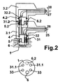
Fig.2 eine doppelte Steckkontakt-Paarung - Für beide Figuren gilt die folgende Beschreibung:
- Der Stecktopf (1) der Steckkontakt-Paarung ist in dem Gehäuse eines elektrischen Apparates (Maschinengehäuse) fest angebracht. Er weist in seinem zylindrischen Innenraum Kontaktstifte (31) auf, die parallel zur Achse des Stecktopfes ausgerichtet sind, den Topfboden durchdringen und in den Innenraum des Stecktopfes hineinragen. Mit den aus dem Topfboden -abgewandt vom Topfbodenherausragenden Enden der Kontaktstifte sind die Leitungsenden 25,26 verlötet.
- Der bewegliche Steckkopf (2) entspricht in seiner Kontur dem Innenraum des Stecktopfes. Er weist die parallel zu seiner Zylinderachse ausgerichteten Kontaktbuchsen (32) auf, die dieselbe geometrische Anordnung wie die Kontaktstifte im Stecktopf haben und durch Einstecken des Steckkopfes in den Stecktopf mit diesen in Verbindung gebracht werden. Da Kontaktstifte und Kontaktbuchsen assymetrisch verteilt sind, ragt ein Führungsstift 6 parallel zu den Kontaktstiften in das Topfinnere und der Steckkopf besitzt in der identischen geometrischen Lage eine Führungsbohrung 7. Die Kontaktbuchsen sind mit ihren freien Enden - abgewandt von den Einstecköffnungen- mit den elektrischen Leitungsenden (25,26) verlötet. Die elektrischen Leitungen (25,26) sind in dem Steckergehäuse - abgewandt von dem Steckkopf- geführt. Der Steckkopf ist mit der Teillänge, welche im eingesteckten Zustand über den Rand des Stecktopfes hinausragt, in dem insoweit kongruenten Innenraum des Steckergehäuses befestigt.
- Dies geschieht durch eine formschlüssige Befestigung. Dazu ist ein Profilring, vorzugsweise O-Ring, als Befestigungsring 4 bezeichnet, mit einem Teil seines Profils in eine Umfangsnut auf dem Außenumfang des in dem Innenraum des Steckergehäuses untergebrachten Endes des Steckkopfes eingelegt. Mit dem Rest seines Profilquerschnitts rastet der Befestigungsring 4 in eine Nut auf dem Innenumfang des Steckergehäuses ein, wobei die Querschnittsebene des Steckkopfes, in welchem diese Nut angebrachte ist, die Eintauchtiefe des Steckkopfes in das Steckergehäuse festlegt.
- Zur formschlüssigen Befestigung nach dem Einstecken des in den Stecktopf eingesteckten Steckkopfes dient dient ein weiterer Profilring, vorzugsweise O-Ring, als Sicherungsring 5 bezeichnet. Dieser ist in eine Umfangsnut des Steckkopfes mit einem Teil seines Querschnitts eingelassen und beim dem Einstecken des Steckkopfes in den Stecktopf rastet der Sicherungsring 5 mit dem Rest seines Querschnitts in eine Nut auf dem Innenumfang des Stecktopfes ein.
- Dabei ist diese Sicherungsring-Verbindung einschließlich Nuten und Sicherungsring 5 nach Form und Material so ausgebildet ist, dass der der mobile Steckkopf (2) nur mit einer einen Grenzwert überschreitenden Zugkraft aus dem im Maschinengestell befestigten Stecktopf (1) herausgezogen werden kann. Es muß insbesondere vermieden werden, dass der Steckkopf unbeabsichtigt oder ohne menschliche Einwirkung aus dem Stecktopf fältt.
- Andererseits ist die Befestigung des Steckkopfes (2) in dem Steckergehäuse (3) durch den Befestigungsring 4 noch "strammer"; d.h.: die Befestigungsring-Verbindung zwischen Steckergehäuse und Steckkopf einschließlich Nuten und Ring 4 ist nach Form, Material und Nutenform im Vergleich zu der Sicherungsring-Verbindung einschließlich Nuten und Ring 5 so ausgebildet ist, dass die Zugkraft mit welcher der Steckkopf aus dem Stecktopf herausgezogen werden kann, kleiner ist als diejenige, mit der der Steckkopf durch die Befestigungsring-Verbindung in dem Steckergehäuse gehalten wird. Es kann also nicht geschehen, dass bei dem Versuch, den Steckkopf aus dem Stecktopf herauszuziehen, versehentlich das Steckergehäuse vom Steckkopf abgezogen wird und dadurch die Leitungsenden gfls. von den Enden der Kontaktbuchsen abgerissen werden.
- Für
Fig.2 gilt darüber hinaus die folgende Beschreibung: - Das Steckergehäuse 3.1 der ersten Steckkontakt-Paarung enthält den ortsfesten Teil, d.h. Stecktopf 2.1 einer zweiten Steckkontakt-Paarung. Diese ist im Beispiel identisch der ersten aufgebaut mit den Teilen Stecktopf 2.2 statt 2, Steckkopf 1.1 statt 1, Gehäuse 3.1 statt 3, die Leitungen/ Leitungsenden 27,28 zusätzlich zu Leitungen/ Leitungsenden 25,26, Kontaktstifte 31.2 statt 31, Kontaktbuchsen 32.2 statt 32, Befestigungsring 4.2 statt 4; Sicherungsring 5.2 statt 5.
- Folgende Besonderheiten gelten insbesondere für das Ausführungsbeispiel:
- Die Steckrichtungen sind für beide Paarungen gleich.
- Die Austrittsrichtungen der Leitungsenden 27,28 und der Leitungsenden 25,26, sind gleichgerichtet
- Die erste Steckkontakt-Paarung weist Leitungsverbindungen zu den Kontaktbuchsen 32.2 und Kontaktstiften 32.2 der zweiten Steckkontakt-Paarung auf. Hierzu sehen in dem Ausführungsbeispiel Stecktopf und Steckkopf der ersten Steckkontakt-Paarung Löcher 33 für die Kontaktstifte 31-2 der zweiten Steckkontakt-Paarung vor, die in dem Stecktopf 2.1 der zweiten Steckkontakt-Paarung mit der entsprechenden Länge befestigt sind.
- Der Stecktopf 2.1 ist im Steckergehäuse 3.1 der ersten Steckkontakt-Paarung in einer dafür vorgesehenen Ausnehmung fest angebracht.
- Die Führungsstifte 6, 6.2 und Führungsbohrungen sind zu einander versetzt.
Claims (4)
- Steckkontakt-Paarung
bestehend aus einem Stecktopf (1) und Kontaktstiften (31) in dem Innenraum des Stecktopfes,
und einem Steckkopf (2), welcher an seinem einen Ende mit Kontaktbuchsen (32) zur Verbindung elektrischer Leitungsenden (25,26) versehen und mit seinem anderen Ende in einem zu diesem Ende kongruenten und beweglichen Steckergehäuses (3), befestigt ist, und
mit einer formschlüssigen Befestigung sowohl der Steckkontakt Paarung aus Steckkopf (2) und Stecktopf (1) als auch der Paarung von Steckkopf (2) und Steckergehäuses (3) jeweils im eingesteckten Zustand ,
wobei
die formschlüssig Befestigung aus Profilringen, vorzugsweise O-Ringen besteht, wobei der Sicherungsring (5) der Steckkontakt Paarung von Steckkopf (2) und Stecktopf (1) in einer Umfangsnut des Steckkopfes mit einem Teil seines Querschnitts eingelassen ist und bei Schließen der Steckkontakt Paarung mit dem Rest seines Querschnitts in eine Nut auf dem Innenumfang des Stecktopfes einrastet, und diese Sicherungsring-Verbindung einschließlich Nuten und Sicherungsring nach Form und Material des Rings sowie Nutenform so ausgebildet ist, dass der Steckkopf (2) nur mit einer einen Grenzwert überschreitenden Zugkraft aus dem Stecktopf (1) herausgezogen werden kann,
dadurch gekennzeichnet, daβ
der Befestigungsring (4) der Paarung von Steckkopf (2) und Steckergehäuse (3) mit einem Teil seines Profils in eine Umfangsnut auf dem Außenumfang des besagten Endes des Steckkopfes eingelegt ist und mit dem Rest seines Profilquerschnitts in eine Nut auf dem Innenumfang des Steckergehäuses einrastet.
und diese Befestigungsring-Verbindung einschließlich Nuten und Ring nach Form, Material und Nutenform im Vergleich zu der Sicherungsring-Verbindung so ausgebildet ist, dass die Zugkraft, mit welcher der Steckkopf aus dem Stecktopf herausgezogen werden kann, kleiner ist als diejenige, mit der der Steckkopf durch die Befestigungsring-Verbindung in dem Steckergehäuse gehalten wird. - Steckkontakt Paarung nach Anspruch 1,
dadurch gekennzeichnet, daß
der Stecktopf mit Kontaktstiften (31) im Maschinengehäuse fest angebracht ist und
das Steckergehäuse den ortsfesten Teil einer zweiten Steckkontakt-Paarung für den Kontakt zusätzlicher Leitungen/ Leitungsenden (27,28) enthält. - Steckkontakt-Paarung nach Anspruch 2
dadurch gekennzeichnet, daß
im Steckergehäuse der ersten Steckkontakt-Paarung der zylindrische Stecktopf der zweiten Steckkontakt-Paarung mit Kontaktstiften (31) und Kontaktbuchsen angebracht ist,
welche über Kontaktbuchsen (32) und Kontaktstifte der ersten Steckkontakt-Paarung ein Verbindung zu zweiten elektrischen Leitungsenden (27,28) herstellen. - Steckkontakt-Paarung nach Anspruch 2
dadurch gekennzeichnet, daß,
die Steckrichtung der ersten Steckkontakt-Paarung und der zweiten Steckkontakt-Paarung gleich ist.
Priority Applications (1)
| Application Number | Priority Date | Filing Date | Title |
|---|---|---|---|
| PL08758021T PL2149176T3 (pl) | 2007-05-12 | 2008-05-06 | Złącze wtykowe |
Applications Claiming Priority (3)
| Application Number | Priority Date | Filing Date | Title |
|---|---|---|---|
| DE102007022600 | 2007-05-12 | ||
| DE102007022598 | 2007-05-12 | ||
| PCT/DE2008/000761 WO2008138303A1 (de) | 2007-05-12 | 2008-05-06 | Steckkontakt-paarung |
Publications (2)
| Publication Number | Publication Date |
|---|---|
| EP2149176A1 EP2149176A1 (de) | 2010-02-03 |
| EP2149176B1 true EP2149176B1 (de) | 2011-02-16 |
Family
ID=39869014
Family Applications (1)
| Application Number | Title | Priority Date | Filing Date |
|---|---|---|---|
| EP08758021A Not-in-force EP2149176B1 (de) | 2007-05-12 | 2008-05-06 | Steckkontakt-paarung |
Country Status (5)
| Country | Link |
|---|---|
| EP (1) | EP2149176B1 (de) |
| AU (1) | AU2008250785B2 (de) |
| DE (2) | DE112008001198A5 (de) |
| PL (1) | PL2149176T3 (de) |
| WO (1) | WO2008138303A1 (de) |
Family Cites Families (7)
| Publication number | Priority date | Publication date | Assignee | Title |
|---|---|---|---|---|
| US2761111A (en) * | 1953-02-16 | 1956-08-28 | Amphenol Electronics Corp | Breakaway connector |
| DE1515685A1 (de) * | 1965-10-19 | 1970-07-02 | Euchner & Co | Steckverbindung |
| GB8418329D0 (en) * | 1984-07-18 | 1984-08-22 | Amp Great Britain | Bipartite electrical connector with sealing means |
| DE19942921C2 (de) * | 1999-08-20 | 2001-09-13 | Amphenol Tuchel Elect | Steckverbinder, insbesondere Winkelsteckverbinder |
| JP2004253163A (ja) * | 2003-02-18 | 2004-09-09 | Yazaki Corp | 中継端子及びコネクタ |
| EP1604430A4 (de) * | 2003-02-18 | 2007-11-07 | Medconx Inc | Elektrischer stecker für eine medizinische vorrichtung mit abgestimmtem presssitz |
| US7234956B2 (en) * | 2005-09-02 | 2007-06-26 | Kauffman George M | Electrical connector with dual independent coupling means |
-
2008
- 2008-05-06 EP EP08758021A patent/EP2149176B1/de not_active Not-in-force
- 2008-05-06 PL PL08758021T patent/PL2149176T3/pl unknown
- 2008-05-06 DE DE112008001198T patent/DE112008001198A5/de not_active Withdrawn
- 2008-05-06 WO PCT/DE2008/000761 patent/WO2008138303A1/de not_active Ceased
- 2008-05-06 AU AU2008250785A patent/AU2008250785B2/en not_active Ceased
- 2008-05-06 DE DE102008022397A patent/DE102008022397A1/de not_active Withdrawn
Also Published As
| Publication number | Publication date |
|---|---|
| WO2008138303A1 (de) | 2008-11-20 |
| EP2149176A1 (de) | 2010-02-03 |
| AU2008250785A1 (en) | 2008-11-20 |
| PL2149176T3 (pl) | 2011-07-29 |
| AU2008250785B2 (en) | 2012-01-12 |
| DE102008022397A1 (de) | 2008-11-20 |
| DE112008001198A5 (de) | 2010-01-28 |
Similar Documents
| Publication | Publication Date | Title |
|---|---|---|
| DE102010021303B4 (de) | Elektrische Steckverbindung, insbesondere Rundsteckverbindung | |
| DE102008017423B4 (de) | Überspannungsschutzgerät | |
| DE3026386A1 (de) | Steckverbindung mit visueller, tastbarer und hoerbarer anzeige | |
| DE112019001325B4 (de) | Verbinder | |
| EP1977484A1 (de) | Koaxiale steckverbinderanordnung | |
| DE102015015202B4 (de) | Steckverbinder und Stecksystem | |
| DE2822365A1 (de) | Elektrischer steckverbinder | |
| EP4066325B1 (de) | Sekundärverriegelungsvorrichtung | |
| WO2017036439A1 (de) | Halterahmen für steckverbindermodule | |
| EP3210264A1 (de) | Elektrisches steckverbinderpaar | |
| EP2754211A1 (de) | Kontaktgeschützter steckverbinder | |
| DE202016104726U1 (de) | Federkontaktstift mit einer Hülse | |
| DE102010022690B4 (de) | Elektrischer Steckverbinder mit PE-Kontakt | |
| EP3742561B1 (de) | Elektrische steckverbindung | |
| DE112013004363T5 (de) | Sichtbares Keilnutausrichtungsmerkmal | |
| DE102014101665A1 (de) | Elektrische Leiterplattensteckverbindung | |
| DE102016104082B3 (de) | Elektrische Steckvorrichtung mit einem Rastmechanismus | |
| DE19854440A1 (de) | Verlängerungsstück für Leuchtstofflampen | |
| WO2008138303A1 (de) | Steckkontakt-paarung | |
| WO2018153409A1 (de) | Anschlusselement | |
| DE202016102938U1 (de) | Steckverbindung | |
| DE4240261A1 (de) | Steckverbinder | |
| DE202008011281U1 (de) | Befestigungseinrichtung | |
| DE19926430C1 (de) | Elektrische Steckvorrichtung | |
| DE102016211076B4 (de) | Medizintechnische Mehrfachbuchse, medizintechnisches Gerät und medizintechnisches System |
Legal Events
| Date | Code | Title | Description |
|---|---|---|---|
| PUAI | Public reference made under article 153(3) epc to a published international application that has entered the european phase |
Free format text: ORIGINAL CODE: 0009012 |
|
| 17P | Request for examination filed |
Effective date: 20091211 |
|
| AK | Designated contracting states |
Kind code of ref document: A1 Designated state(s): AT BE BG CH CY CZ DE DK EE ES FI FR GB GR HR HU IE IS IT LI LT LU LV MC MT NL NO PL PT RO SE SI SK TR |
|
| AX | Request for extension of the european patent |
Extension state: AL BA MK RS |
|
| RAP1 | Party data changed (applicant data changed or rights of an application transferred) |
Owner name: TIEFENBACH CONTROL SYSTEMS GMBH |
|
| GRAP | Despatch of communication of intention to grant a patent |
Free format text: ORIGINAL CODE: EPIDOSNIGR1 |
|
| RIC1 | Information provided on ipc code assigned before grant |
Ipc: H01R 31/06 20060101ALI20100630BHEP Ipc: H01R 13/52 20060101AFI20100630BHEP Ipc: H01R 13/56 20060101ALI20100630BHEP |
|
| DAX | Request for extension of the european patent (deleted) | ||
| GRAS | Grant fee paid |
Free format text: ORIGINAL CODE: EPIDOSNIGR3 |
|
| GRAA | (expected) grant |
Free format text: ORIGINAL CODE: 0009210 |
|
| AK | Designated contracting states |
Kind code of ref document: B1 Designated state(s): AT BE BG CH CY CZ DE DK EE ES FI FR GB GR HR HU IE IS IT LI LT LU LV MC MT NL NO PL PT RO SE SI SK TR |
|
| REG | Reference to a national code |
Ref country code: GB Ref legal event code: FG4D Free format text: NOT ENGLISH |
|
| REG | Reference to a national code |
Ref country code: CH Ref legal event code: EP |
|
| REG | Reference to a national code |
Ref country code: IE Ref legal event code: FG4D Free format text: LANGUAGE OF EP DOCUMENT: GERMAN |
|
| REF | Corresponds to: |
Ref document number: 502008002618 Country of ref document: DE Date of ref document: 20110331 Kind code of ref document: P |
|
| REG | Reference to a national code |
Ref country code: DE Ref legal event code: R096 Ref document number: 502008002618 Country of ref document: DE Effective date: 20110331 |
|
| REG | Reference to a national code |
Ref country code: NL Ref legal event code: VDEP Effective date: 20110216 |
|
| LTIE | Lt: invalidation of european patent or patent extension |
Effective date: 20110216 |
|
| PG25 | Lapsed in a contracting state [announced via postgrant information from national office to epo] |
Ref country code: HR Free format text: LAPSE BECAUSE OF FAILURE TO SUBMIT A TRANSLATION OF THE DESCRIPTION OR TO PAY THE FEE WITHIN THE PRESCRIBED TIME-LIMIT Effective date: 20110216 Ref country code: LV Free format text: LAPSE BECAUSE OF FAILURE TO SUBMIT A TRANSLATION OF THE DESCRIPTION OR TO PAY THE FEE WITHIN THE PRESCRIBED TIME-LIMIT Effective date: 20110216 Ref country code: ES Free format text: LAPSE BECAUSE OF FAILURE TO SUBMIT A TRANSLATION OF THE DESCRIPTION OR TO PAY THE FEE WITHIN THE PRESCRIBED TIME-LIMIT Effective date: 20110527 Ref country code: PT Free format text: LAPSE BECAUSE OF FAILURE TO SUBMIT A TRANSLATION OF THE DESCRIPTION OR TO PAY THE FEE WITHIN THE PRESCRIBED TIME-LIMIT Effective date: 20110616 Ref country code: NO Free format text: LAPSE BECAUSE OF FAILURE TO SUBMIT A TRANSLATION OF THE DESCRIPTION OR TO PAY THE FEE WITHIN THE PRESCRIBED TIME-LIMIT Effective date: 20110516 Ref country code: SE Free format text: LAPSE BECAUSE OF FAILURE TO SUBMIT A TRANSLATION OF THE DESCRIPTION OR TO PAY THE FEE WITHIN THE PRESCRIBED TIME-LIMIT Effective date: 20110216 Ref country code: GR Free format text: LAPSE BECAUSE OF FAILURE TO SUBMIT A TRANSLATION OF THE DESCRIPTION OR TO PAY THE FEE WITHIN THE PRESCRIBED TIME-LIMIT Effective date: 20110517 Ref country code: LT Free format text: LAPSE BECAUSE OF FAILURE TO SUBMIT A TRANSLATION OF THE DESCRIPTION OR TO PAY THE FEE WITHIN THE PRESCRIBED TIME-LIMIT Effective date: 20110216 |
|
| REG | Reference to a national code |
Ref country code: PL Ref legal event code: T3 |
|
| PG25 | Lapsed in a contracting state [announced via postgrant information from national office to epo] |
Ref country code: SI Free format text: LAPSE BECAUSE OF FAILURE TO SUBMIT A TRANSLATION OF THE DESCRIPTION OR TO PAY THE FEE WITHIN THE PRESCRIBED TIME-LIMIT Effective date: 20110216 Ref country code: BG Free format text: LAPSE BECAUSE OF FAILURE TO SUBMIT A TRANSLATION OF THE DESCRIPTION OR TO PAY THE FEE WITHIN THE PRESCRIBED TIME-LIMIT Effective date: 20110516 Ref country code: NL Free format text: LAPSE BECAUSE OF FAILURE TO SUBMIT A TRANSLATION OF THE DESCRIPTION OR TO PAY THE FEE WITHIN THE PRESCRIBED TIME-LIMIT Effective date: 20110216 Ref country code: FI Free format text: LAPSE BECAUSE OF FAILURE TO SUBMIT A TRANSLATION OF THE DESCRIPTION OR TO PAY THE FEE WITHIN THE PRESCRIBED TIME-LIMIT Effective date: 20110216 Ref country code: CY Free format text: LAPSE BECAUSE OF FAILURE TO SUBMIT A TRANSLATION OF THE DESCRIPTION OR TO PAY THE FEE WITHIN THE PRESCRIBED TIME-LIMIT Effective date: 20110216 |
|
| REG | Reference to a national code |
Ref country code: IE Ref legal event code: FD4D |
|
| PG25 | Lapsed in a contracting state [announced via postgrant information from national office to epo] |
Ref country code: EE Free format text: LAPSE BECAUSE OF FAILURE TO SUBMIT A TRANSLATION OF THE DESCRIPTION OR TO PAY THE FEE WITHIN THE PRESCRIBED TIME-LIMIT Effective date: 20110216 Ref country code: DK Free format text: LAPSE BECAUSE OF FAILURE TO SUBMIT A TRANSLATION OF THE DESCRIPTION OR TO PAY THE FEE WITHIN THE PRESCRIBED TIME-LIMIT Effective date: 20110216 Ref country code: IE Free format text: LAPSE BECAUSE OF FAILURE TO SUBMIT A TRANSLATION OF THE DESCRIPTION OR TO PAY THE FEE WITHIN THE PRESCRIBED TIME-LIMIT Effective date: 20110216 |
|
| BERE | Be: lapsed |
Owner name: TIEFENBACH CONTROL SYSTEMS G.M.B.H. Effective date: 20110531 |
|
| PG25 | Lapsed in a contracting state [announced via postgrant information from national office to epo] |
Ref country code: SK Free format text: LAPSE BECAUSE OF FAILURE TO SUBMIT A TRANSLATION OF THE DESCRIPTION OR TO PAY THE FEE WITHIN THE PRESCRIBED TIME-LIMIT Effective date: 20110216 Ref country code: RO Free format text: LAPSE BECAUSE OF FAILURE TO SUBMIT A TRANSLATION OF THE DESCRIPTION OR TO PAY THE FEE WITHIN THE PRESCRIBED TIME-LIMIT Effective date: 20110216 Ref country code: CZ Free format text: LAPSE BECAUSE OF FAILURE TO SUBMIT A TRANSLATION OF THE DESCRIPTION OR TO PAY THE FEE WITHIN THE PRESCRIBED TIME-LIMIT Effective date: 20110216 |
|
| PLBE | No opposition filed within time limit |
Free format text: ORIGINAL CODE: 0009261 |
|
| STAA | Information on the status of an ep patent application or granted ep patent |
Free format text: STATUS: NO OPPOSITION FILED WITHIN TIME LIMIT |
|
| PG25 | Lapsed in a contracting state [announced via postgrant information from national office to epo] |
Ref country code: MT Free format text: LAPSE BECAUSE OF FAILURE TO SUBMIT A TRANSLATION OF THE DESCRIPTION OR TO PAY THE FEE WITHIN THE PRESCRIBED TIME-LIMIT Effective date: 20110216 Ref country code: MC Free format text: LAPSE BECAUSE OF NON-PAYMENT OF DUE FEES Effective date: 20110531 |
|
| 26N | No opposition filed |
Effective date: 20111117 |
|
| REG | Reference to a national code |
Ref country code: FR Ref legal event code: ST Effective date: 20120131 |
|
| REG | Reference to a national code |
Ref country code: DE Ref legal event code: R097 Ref document number: 502008002618 Country of ref document: DE Effective date: 20111117 |
|
| PG25 | Lapsed in a contracting state [announced via postgrant information from national office to epo] |
Ref country code: BE Free format text: LAPSE BECAUSE OF NON-PAYMENT OF DUE FEES Effective date: 20110531 |
|
| PG25 | Lapsed in a contracting state [announced via postgrant information from national office to epo] |
Ref country code: FR Free format text: LAPSE BECAUSE OF NON-PAYMENT OF DUE FEES Effective date: 20110531 |
|
| PG25 | Lapsed in a contracting state [announced via postgrant information from national office to epo] |
Ref country code: IT Free format text: LAPSE BECAUSE OF FAILURE TO SUBMIT A TRANSLATION OF THE DESCRIPTION OR TO PAY THE FEE WITHIN THE PRESCRIBED TIME-LIMIT Effective date: 20110216 |
|
| REG | Reference to a national code |
Ref country code: CH Ref legal event code: PL |
|
| GBPC | Gb: european patent ceased through non-payment of renewal fee |
Effective date: 20120506 |
|
| PG25 | Lapsed in a contracting state [announced via postgrant information from national office to epo] |
Ref country code: LI Free format text: LAPSE BECAUSE OF NON-PAYMENT OF DUE FEES Effective date: 20120531 Ref country code: CH Free format text: LAPSE BECAUSE OF NON-PAYMENT OF DUE FEES Effective date: 20120531 |
|
| PG25 | Lapsed in a contracting state [announced via postgrant information from national office to epo] |
Ref country code: GB Free format text: LAPSE BECAUSE OF NON-PAYMENT OF DUE FEES Effective date: 20120506 |
|
| PG25 | Lapsed in a contracting state [announced via postgrant information from national office to epo] |
Ref country code: LU Free format text: LAPSE BECAUSE OF NON-PAYMENT OF DUE FEES Effective date: 20110506 |
|
| PG25 | Lapsed in a contracting state [announced via postgrant information from national office to epo] |
Ref country code: IS Free format text: LAPSE BECAUSE OF FAILURE TO SUBMIT A TRANSLATION OF THE DESCRIPTION OR TO PAY THE FEE WITHIN THE PRESCRIBED TIME-LIMIT Effective date: 20110216 |
|
| PG25 | Lapsed in a contracting state [announced via postgrant information from national office to epo] |
Ref country code: TR Free format text: LAPSE BECAUSE OF FAILURE TO SUBMIT A TRANSLATION OF THE DESCRIPTION OR TO PAY THE FEE WITHIN THE PRESCRIBED TIME-LIMIT Effective date: 20110216 |
|
| PG25 | Lapsed in a contracting state [announced via postgrant information from national office to epo] |
Ref country code: HU Free format text: LAPSE BECAUSE OF FAILURE TO SUBMIT A TRANSLATION OF THE DESCRIPTION OR TO PAY THE FEE WITHIN THE PRESCRIBED TIME-LIMIT Effective date: 20110216 |
|
| REG | Reference to a national code |
Ref country code: AT Ref legal event code: MM01 Ref document number: 498924 Country of ref document: AT Kind code of ref document: T Effective date: 20130506 |
|
| PG25 | Lapsed in a contracting state [announced via postgrant information from national office to epo] |
Ref country code: AT Free format text: LAPSE BECAUSE OF NON-PAYMENT OF DUE FEES Effective date: 20130506 |
|
| PGFP | Annual fee paid to national office [announced via postgrant information from national office to epo] |
Ref country code: PL Payment date: 20150504 Year of fee payment: 8 |
|
| PGFP | Annual fee paid to national office [announced via postgrant information from national office to epo] |
Ref country code: DE Payment date: 20160330 Year of fee payment: 9 |
|
| PG25 | Lapsed in a contracting state [announced via postgrant information from national office to epo] |
Ref country code: PL Free format text: LAPSE BECAUSE OF NON-PAYMENT OF DUE FEES Effective date: 20160506 |
|
| REG | Reference to a national code |
Ref country code: DE Ref legal event code: R119 Ref document number: 502008002618 Country of ref document: DE |
|
| PG25 | Lapsed in a contracting state [announced via postgrant information from national office to epo] |
Ref country code: DE Free format text: LAPSE BECAUSE OF NON-PAYMENT OF DUE FEES Effective date: 20171201 |