EP2149125B1 - Rfid key switch with integrated key circuitry - Google Patents
Rfid key switch with integrated key circuitry Download PDFInfo
- Publication number
- EP2149125B1 EP2149125B1 EP08755281.6A EP08755281A EP2149125B1 EP 2149125 B1 EP2149125 B1 EP 2149125B1 EP 08755281 A EP08755281 A EP 08755281A EP 2149125 B1 EP2149125 B1 EP 2149125B1
- Authority
- EP
- European Patent Office
- Prior art keywords
- key
- rfid
- assembly
- switch
- processing circuitry
- Prior art date
- Legal status (The legal status is an assumption and is not a legal conclusion. Google has not performed a legal analysis and makes no representation as to the accuracy of the status listed.)
- Active
Links
Images

Classifications
-
- G—PHYSICS
- G07—CHECKING-DEVICES
- G07C—TIME OR ATTENDANCE REGISTERS; REGISTERING OR INDICATING THE WORKING OF MACHINES; GENERATING RANDOM NUMBERS; VOTING OR LOTTERY APPARATUS; ARRANGEMENTS, SYSTEMS OR APPARATUS FOR CHECKING NOT PROVIDED FOR ELSEWHERE
- G07C9/00—Individual registration on entry or exit
- G07C9/00174—Electronically operated locks; Circuits therefor; Nonmechanical keys therefor, e.g. passive or active electrical keys or other data carriers without mechanical keys
- G07C9/00182—Electronically operated locks; Circuits therefor; Nonmechanical keys therefor, e.g. passive or active electrical keys or other data carriers without mechanical keys operated with unidirectional data transmission between data carrier and locks
-
- G—PHYSICS
- G07—CHECKING-DEVICES
- G07C—TIME OR ATTENDANCE REGISTERS; REGISTERING OR INDICATING THE WORKING OF MACHINES; GENERATING RANDOM NUMBERS; VOTING OR LOTTERY APPARATUS; ARRANGEMENTS, SYSTEMS OR APPARATUS FOR CHECKING NOT PROVIDED FOR ELSEWHERE
- G07C9/00—Individual registration on entry or exit
- G07C9/00174—Electronically operated locks; Circuits therefor; Nonmechanical keys therefor, e.g. passive or active electrical keys or other data carriers without mechanical keys
- G07C2009/00753—Electronically operated locks; Circuits therefor; Nonmechanical keys therefor, e.g. passive or active electrical keys or other data carriers without mechanical keys operated by active electrical keys
- G07C2009/00761—Electronically operated locks; Circuits therefor; Nonmechanical keys therefor, e.g. passive or active electrical keys or other data carriers without mechanical keys operated by active electrical keys with data transmission performed by connected means, e.g. mechanical contacts, plugs, connectors
-
- G—PHYSICS
- G07—CHECKING-DEVICES
- G07C—TIME OR ATTENDANCE REGISTERS; REGISTERING OR INDICATING THE WORKING OF MACHINES; GENERATING RANDOM NUMBERS; VOTING OR LOTTERY APPARATUS; ARRANGEMENTS, SYSTEMS OR APPARATUS FOR CHECKING NOT PROVIDED FOR ELSEWHERE
- G07C9/00—Individual registration on entry or exit
- G07C9/00174—Electronically operated locks; Circuits therefor; Nonmechanical keys therefor, e.g. passive or active electrical keys or other data carriers without mechanical keys
- G07C2009/00753—Electronically operated locks; Circuits therefor; Nonmechanical keys therefor, e.g. passive or active electrical keys or other data carriers without mechanical keys operated by active electrical keys
- G07C2009/00769—Electronically operated locks; Circuits therefor; Nonmechanical keys therefor, e.g. passive or active electrical keys or other data carriers without mechanical keys operated by active electrical keys with data transmission performed by wireless means
- G07C2009/00793—Electronically operated locks; Circuits therefor; Nonmechanical keys therefor, e.g. passive or active electrical keys or other data carriers without mechanical keys operated by active electrical keys with data transmission performed by wireless means by Hertzian waves
-
- Y—GENERAL TAGGING OF NEW TECHNOLOGICAL DEVELOPMENTS; GENERAL TAGGING OF CROSS-SECTIONAL TECHNOLOGIES SPANNING OVER SEVERAL SECTIONS OF THE IPC; TECHNICAL SUBJECTS COVERED BY FORMER USPC CROSS-REFERENCE ART COLLECTIONS [XRACs] AND DIGESTS
- Y10—TECHNICAL SUBJECTS COVERED BY FORMER USPC
- Y10T—TECHNICAL SUBJECTS COVERED BY FORMER US CLASSIFICATION
- Y10T70/00—Locks
- Y10T70/70—Operating mechanism
- Y10T70/7051—Using a powered device [e.g., motor]
- Y10T70/7062—Electrical type [e.g., solenoid]
- Y10T70/7068—Actuated after correct combination recognized [e.g., numerical, alphabetical, or magnet[s] pattern]
- Y10T70/7073—Including use of a key
- Y10T70/7079—Key rotated [e.g., Eurocylinder]
Definitions
- Embodiments are generally related to Radio frequency identification (RFID) systems and techniques. Embodiments are also related to RFID key switch. Embodiments are additionally related to directly incorporating RFID processing circuitry within key operated system housing.
- RFID Radio frequency identification
- Radio frequency identification systems can be used to detect and prevent inventory shrinkage and to perform inventory management functions in a variety of retail establishments, apparel and mass merchandisers, supermarkets, libraries, video stores, and the like.
- RFID technology provides an inexpensive and simple way to mark and identify physical objects using machine-readable information.
- RFID systems can identify objects at greater distances than optical systems, store information into read/write tags, operate unattended, and read tags hidden from visual inspection for security purposes.
- RFID technology can be applied to identify electronic components, devices, and systems to provide functions such as, for example, security of the assets, inventory tracking of the assets, identification of the assets, and short distance communication between the assets.
- RFID tags are currently integrated into electronic components, devices and systems at the component level (i.e., circuit chip circuit board etc.), the asset level (i.e., box, computer, etc.) or system level (i.e., network system, computer system, etc.). Often RFID tags are used in conjunction with key operated switches to add an enhanced security feature beyond that of the cut or shape of the key.
- component level i.e., circuit chip circuit board etc.
- asset level i.e., box, computer, etc.
- system level i.e., network system, computer system, etc.
- circuitry involved in the processing of the RFID signal transmitted from RIFD tags is typically housed in a separate module from the key switch housing.
- the separate module adds to overall system package size, installation real estate, parts count, and assembly steps involved in the manufacturing and installation processes.
- US 6 442 985 discloses a lock apparatus and lock system wherein the lock apparatus can be locked or unlocked by an electronic key or mechanical key and includes a cylinder casing a sleeve disposed radially inside the silly cylinder casing and a key cylinder disposed rotatably inside the sleeve and in which a mechanical key can be inserted.
- the apparatus further comprising electronic ID verification.
- FR 2 755 791 discloses an electronic key contact assembly for automobiles has a static housing and a rotatable assembly.
- the rotatable assembly comprises a housing having a key receiving slot and spring terminals.
- US2005/0012593 discloses a modular vehicle ignition system that is capable of housing various components, such as a lock cylinder, a remote keyless entry transceiver (RKE), a radio frequency identification transceiver (RFID), an operator identification system, a steering column lock and an ignition switch.
- RKE remote keyless entry transceiver
- RFID radio frequency identification transceiver
- the invention includes an RFID key switch which can be used in any application where a typical key operated switch is employed.
- the RFID key assembly includes four subassemblies.
- the Key/Tumbler Assembly is the first main subassembly enables the insertion of key into the keyed switch, providing a means to rotate internal switch contacts.
- the second main assembly can be RFID Processing Circuitry which operates to read transmitted RF signals from an RFID tag associated with a key. Rotating and stationary switch contacts make up the third subassembly, which provide the function of opening and closing contacts within the switch, which ultimately serve to inactivate or activate equipment usage.
- the fourth subassembly is an electrical connection interface which enables the switch to be coupled to associated equipment and enables the transmission of closed circuit status and/or RFID code information from the processing circuitry to the equipment upon which the switch is installed to be utilized.
- the RFID processing circuitry is directly incorporated into the key switch housing itself, thereby eliminating the need for separate modules and simplifying installation.
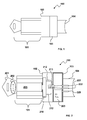
- An RFID-enabled key switch assembly 100 in accordance with features of the present invention.
- An RFID-enabled key switch assembly 100 which can be implemented in accordance with a preferred embodiment, includes four main subassemblies.
- the four main components includes an RFID key and tumbler assembly module 101, rotating and stationary contact assembly module 102, RFID processing circuitry module 103 and an electrical connection interface 104.
- FIG. 2 across-sectional view 200 of the RFID-enabled key switch assembly shown in FIG. 1 is illustrated.
- a key 201 including an embedded RFID tag 202 is inserted into the key and tumbler assembly module 101 wherein a tumbler 205, which is coupled to rotating switch and contact assembly 210 located within rotating and stationary contact assembly module 102, can be rotated by rotation of a valid key 201 and thereby enable the rotation of the rotating switch contact assembly 210 so that rotating contacts 212 located thereon can come into electrical contact with stationary contacts 213.
- the RFID signals transmitted from the RFID tag 202 embedded in the key 201 can be read by the RFID processing circuitry 203. If rotation of the key 201 within the tumbler assembly module 101 is successful, an electrical circuit is closed contact between rotating contacts 212 and stationary contacts 213. Assuming that the RFID tag is authenticated/validated by the RFID processing circuitry 203, then signals can be passed into equipment (not shown) though contacts 221, 222 and 223 assuming a coupling with the equipment via the electrical connection interface 104.
- the electrical connection interface 104 can comprise of wire leads, an integral connector, or screw terminals (not shown in figure), having the purpose of transmitting the RFID code from the processing circuitry 203 to the equipment upon which the switch assembly 200 can be installed.
- a key switch assembly incorporating RFID processing circuitry within its housing is provided, thereby eliminating the need for a separate module.
- an RFID tag key's insertion into the key and tumbler assembly of the key switch is enabled.
- RFID signal is read from the key by RFID processing circuitry located within the switch after the key's insertion into the switch.
- the RFID circuitry validates the key's authenticity concurrent with manual key operation.
- concurrent manual key operation and key authenticity validation enables use of equipment on which the switch is installed.
- the access process terminates.
- RFID authentication enables operation of the key's rotation.
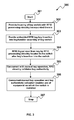
- the process begins as shown in block 401.
- a housing of a key switch is provided with RFID processing circuitry incorporated therein.
- RFID tag key insertion into the key and tumbler assembly of the key switch is enabled.
- an RFID signal is read from the key by RFID processing circuitry.
- the RFID circuitry validates the key's authenticity.
- authentication of the key enables functions of opening and closing circuits of the switch by the rotating and stationary contacts. Thereafter, as shown in block 407, circuits of the switch are closed by contact between rotating and stationary switch contacts thereby enabling use of equipment on which the switch is installed. The process then terminates as shown in block 408.
- the RFID key operated switch finds wide field of application including all terrain vehicles, automobiles, golf carts, utility vehicles, material handling equipment, lawn care equipments, mobile work platforms and home security.
- the invention also prospects application in boom lifts, construction equipments, go karts, snow mobiles, watercraft, elevators, and any other asset that requires key operated switch for enhanced security.
Description
- Embodiments are generally related to Radio frequency identification (RFID) systems and techniques. Embodiments are also related to RFID key switch. Embodiments are additionally related to directly incorporating RFID processing circuitry within key operated system housing.
- Radio frequency identification systems (RFID) can be used to detect and prevent inventory shrinkage and to perform inventory management functions in a variety of retail establishments, apparel and mass merchandisers, supermarkets, libraries, video stores, and the like. RFID technology provides an inexpensive and simple way to mark and identify physical objects using machine-readable information.
- RFID systems can identify objects at greater distances than optical systems, store information into read/write tags, operate unattended, and read tags hidden from visual inspection for security purposes. RFID technology can be applied to identify electronic components, devices, and systems to provide functions such as, for example, security of the assets, inventory tracking of the assets, identification of the assets, and short distance communication between the assets.
- RFID tags are currently integrated into electronic components, devices and systems at the component level (i.e., circuit chip circuit board etc.), the asset level (i.e., box, computer, etc.) or system level (i.e., network system, computer system, etc.). Often RFID tags are used in conjunction with key operated switches to add an enhanced security feature beyond that of the cut or shape of the key.
- One of the problems with such prior art techniques is that circuitry involved in the processing of the RFID signal transmitted from RIFD tags is typically housed in a separate module from the key switch housing. The separate module adds to overall system package size, installation real estate, parts count, and assembly steps involved in the manufacturing and installation processes.
-
US 6 442 985 discloses a lock apparatus and lock system wherein the lock apparatus can be locked or unlocked by an electronic key or mechanical key and includes a cylinder casing a sleeve disposed radially inside the silly cylinder casing and a key cylinder disposed rotatably inside the sleeve and in which a mechanical key can be inserted. The apparatus further comprising electronic ID verification.FR 2 755 791 -
US2005/0012593 discloses a modular vehicle ignition system that is capable of housing various components, such as a lock cylinder, a remote keyless entry transceiver (RKE), a radio frequency identification transceiver (RFID), an operator identification system, a steering column lock and an ignition switch. - Based on the foregoing, a need exists to solve the multiple, separate module issue by incorporating all RFID processing circuitry directly into the housing of the key switch the assembly itself, thereby enhancing security and limiting space requirements for the overall system.
- The present invention in its various aspects is as set out in the appended claims.
- The following summary is provided to facilitate an understanding of some of the innovative features unique to the embodiments disclosed and is not intended to be a full description. A full appreciation of the various aspects of the embodiments can be gained by taking the entire specification, claims, drawings, and abstract as a whole.
- It is, therefore, one aspect of the present invention to provide for an improved RFID key switch assembly.
- It is another aspect of the present invention to incorporate RFID processing circuitry into the housing of the key switch system.
- It is a further aspect of the present invention to provide for an RFID-enhanced, key operated switch for enhanced security.
- The aforementioned aspects and other objectives and advantages can now be achieved as described herein. The invention includes an RFID key switch which can be used in any application where a typical key operated switch is employed. The RFID key assembly includes four subassemblies. The Key/Tumbler Assembly is the first main subassembly enables the insertion of key into the keyed switch, providing a means to rotate internal switch contacts. The second main assembly can be RFID Processing Circuitry which operates to read transmitted RF signals from an RFID tag associated with a key. Rotating and stationary switch contacts make up the third subassembly, which provide the function of opening and closing contacts within the switch, which ultimately serve to inactivate or activate equipment usage. The fourth subassembly is an electrical connection interface which enables the switch to be coupled to associated equipment and enables the transmission of closed circuit status and/or RFID code information from the processing circuitry to the equipment upon which the switch is installed to be utilized. The RFID processing circuitry is directly incorporated into the key switch housing itself, thereby eliminating the need for separate modules and simplifying installation.
- The accompanying figures, in which like reference numerals refer to identical or functionally-similar elements throughout the separate views and which are incorporated in and form a part of the specification, further illustrate the embodiments and, together with the detailed description, serve to explain the embodiments disclosed herein.
-
FIG. 1 is an illustration of the four main modules that comprise a RFID-enabled key switch assembly, which can be implemented in accordance with a preferred embodiment; -
FIG. 2 is a cross section view of the RFID-enabled key switch assembly illustrated inFIG. 1 , but further illustrating operating components within the RFID-enabled key switch assembly, which can be implemented in accordance with a preferred embodiment; -
FIG. 3 illustrates a high-level flow chart of logical operational steps of a method, which can be implemented in accordance with a preferred embodiment; and -
FIG. 4 illustrates another high-level flow chart of logical operational steps of a method, which can be implemented in accordance with a preferred embodiment. - The particular values and configurations discussed in these non-limiting examples can be varied and are cited merely to illustrate at least one embodiment and are not intended to limit the scope thereof.
- Referring to
FIG. 1 , what is illustrated is an RFID-enabledkey switch assembly 100 in accordance with features of the present invention. An RFID-enabledkey switch assembly 100, which can be implemented in accordance with a preferred embodiment, includes four main subassemblies. The four main components includes an RFID key andtumbler assembly module 101, rotating and stationarycontact assembly module 102, RFIDprocessing circuitry module 103 and anelectrical connection interface 104. - As is well known in the art, key and tumbler assemblies allows for the insertion of the key into the assembly to provide a means for rotating the internal mechanism. Referring to
FIG. 2 , across-sectional view 200 of the RFID-enabled key switch assembly shown inFIG. 1 is illustrated. As shown inFIG. 2 , akey 201 including an embeddedRFID tag 202 is inserted into the key andtumbler assembly module 101 wherein atumbler 205, which is coupled to rotating switch andcontact assembly 210 located within rotating and stationarycontact assembly module 102, can be rotated by rotation of avalid key 201 and thereby enable the rotation of the rotatingswitch contact assembly 210 so thatrotating contacts 212 located thereon can come into electrical contact withstationary contacts 213. After installing thekey 201 into theswitch 103, the RFID signals transmitted from theRFID tag 202 embedded in thekey 201 can be read by theRFID processing circuitry 203. If rotation of thekey 201 within thetumbler assembly module 101 is successful, an electrical circuit is closed contact betweenrotating contacts 212 andstationary contacts 213. Assuming that the RFID tag is authenticated/validated by theRFID processing circuitry 203, then signals can be passed into equipment (not shown) thoughcontacts electrical connection interface 104. - It can be appreciated that the
electrical connection interface 104 can comprise of wire leads, an integral connector, or screw terminals (not shown in figure), having the purpose of transmitting the RFID code from theprocessing circuitry 203 to the equipment upon which theswitch assembly 200 can be installed. - Referring to
FIG. 3 , illustrated is a high-level flow chart of logical operational steps of amethod 300, which can be implemented in accordance with a preferred embodiment. As depicted atblock 301, the process can begin. Next, as indicated atblock 302, a key switch assembly incorporating RFID processing circuitry within its housing is provided, thereby eliminating the need for a separate module. Thereafter, as described atblock 303, an RFID tag key's insertion into the key and tumbler assembly of the key switch is enabled. Next, as indicated atblock 304 and RFID signal is read from the key by RFID processing circuitry located within the switch after the key's insertion into the switch. Thereafter, as illustrated atblock 305, the RFID circuitry validates the key's authenticity concurrent with manual key operation. Then, as shown inblock 306, concurrent manual key operation and key authenticity validation enables use of equipment on which the switch is installed. Thereafter, as described atblock 307, the access process terminates. - Referring to
FIG. 4 , illustrated is a high-level flow chart of alternative operational steps for amethod 400 of using the invention, which can be implemented in accordance with a preferred embodiment. In this case RFID authentication enables operation of the key's rotation. The process begins as shown inblock 401. Then, as depicted atblock 402, a housing of a key switch is provided with RFID processing circuitry incorporated therein. Then as shown inblock 403, RFID tag key insertion into the key and tumbler assembly of the key switch is enabled. Thereafter, as shown inblock 404, an RFID signal is read from the key by RFID processing circuitry. Then, as shown inblock 405, the RFID circuitry validates the key's authenticity. Then, as shown inblock 406, authentication of the key enables functions of opening and closing circuits of the switch by the rotating and stationary contacts. Thereafter, as shown inblock 407, circuits of the switch are closed by contact between rotating and stationary switch contacts thereby enabling use of equipment on which the switch is installed. The process then terminates as shown inblock 408. - The RFID key operated switch finds wide field of application including all terrain vehicles, automobiles, golf carts, utility vehicles, material handling equipment, lawn care equipments, mobile work platforms and home security. The invention also prospects application in boom lifts, construction equipments, go karts, snow mobiles, watercraft, elevators, and any other asset that requires key operated switch for enhanced security.
- It will be appreciated that variations of the above-disclosed and other features and functions, or alternatives thereof, may be desirably combined into many other different systems or applications. Also that various presently unforeseen or unanticipated alternatives, modifications, variations or improvements therein may be subsequently made by those skilled in the art which are also intended to be encompassed by the following claims.
Claims (4)
- A key switch assembly (100), comprising:a key switch housing incorporating:a key and tumbler assembly (101) coupled to a rotating contact assembly (102) including rotating contacts (212) adapted to make electrical contact with stationary contacts (213) following rotation of a key within the key and tumbler assembly;RFID processing circuitry (203); andan electrical connection interface (104);wherein insertion of a key (201) including an embedded RFID tag (202) thereon into the key and tumbler assembly (101) causes said RFID processing circuitry (104) to receive an RF signal from the RFID tag for authentication of the RFID tag, and wherein a signal is sent from the RFID processing circuitry together with a signal from stationary contacts (213) when in electrical contact with the rotating contacts (212), said signals enabling use of equipment associated with the key switch.
- The system of claim 1, wherein said key and tumbler assembly (101) is adapted to enable the insertion of an RFID embedded key to rotate said rotating contact assembly (102) and make electrical contact with the stationary contacts (213) if the RF signal is authenticated by the RFID processing circuitry (203).
- The system of claim1, wherein said electrical connection interface (104) transmits the RFID code from said processing circuitry (203) to a vehicle or equipment on which said switch is installed.
- A method using a RFID-enabled key switch assembly (100) to authorize equipment usage, comprising;
providing a key switch housing comprising RFID processing circuitry (203) and a key and tumbler assembly (101) therein, the key and tumbler assembly including a switch having rotating contacts (212) adapted to make electrical contact with stationary contacts (213) following rotation of a key within the key and tumbler assembly;
enabling an embedded RFID tag key (201) to be inserted into the key and tumbler assembly;
reading an RF signal from the embedded RFID tag (202) by said RFID processing circuitry (203) to validate key authenticity;
enabling rotation of said key and tumbler assembly (101), said rotation resulting in electrical contact between the rotating contacts (212) and the stationary contacts (213), thereby closing the circuit of the switch, to enable use of equipment following authenticity by said RFID processing circuitry (203);
transmitting closed circuit status and RFID code status from the RFID-enabled key switch assembly (100) to equipment upon which the RFID-enabled key switch assembly is installed.
Applications Claiming Priority (2)
| Application Number | Priority Date | Filing Date | Title |
|---|---|---|---|
| US11/803,322 US7696878B2 (en) | 2007-05-13 | 2007-05-13 | RFID key switch with integrated key circuitry |
| PCT/US2008/063371 WO2008141261A1 (en) | 2007-05-13 | 2008-05-12 | Rfid key switch with integrated key circuitry |
Publications (2)
| Publication Number | Publication Date |
|---|---|
| EP2149125A1 EP2149125A1 (en) | 2010-02-03 |
| EP2149125B1 true EP2149125B1 (en) | 2015-04-01 |
Family
ID=39639621
Family Applications (1)
| Application Number | Title | Priority Date | Filing Date |
|---|---|---|---|
| EP08755281.6A Active EP2149125B1 (en) | 2007-05-13 | 2008-05-12 | Rfid key switch with integrated key circuitry |
Country Status (5)
| Country | Link |
|---|---|
| US (1) | US7696878B2 (en) |
| EP (1) | EP2149125B1 (en) |
| CN (1) | CN101689315B (en) |
| CA (1) | CA2687278C (en) |
| WO (1) | WO2008141261A1 (en) |
Families Citing this family (12)
| Publication number | Priority date | Publication date | Assignee | Title |
|---|---|---|---|---|
| ES2367755T3 (en) * | 2007-11-23 | 2011-11-08 | Inventio Ag | KEY SWITCH FOR ASSEMBLY IN A MOVEMENT DEVICE AND PROCEDURE FOR HANDLING. |
| EP2113887B1 (en) * | 2008-04-30 | 2013-01-02 | Siemens Aktiengesellschaft | Key switch |
| US8384524B2 (en) * | 2008-11-26 | 2013-02-26 | Honeywell International Inc. | Passive surface acoustic wave sensing system |
| US8699200B2 (en) * | 2010-02-05 | 2014-04-15 | Honeywell International Inc. | Secure non-contact switch |
| US8456792B2 (en) * | 2010-02-05 | 2013-06-04 | Honeywell International Inc. | Secure non-contact switch |
| CN105121761B (en) * | 2012-12-23 | 2019-06-11 | Bv·埃默特克 | The combination of cylinder lock and this lock & key |
| PE20151898A1 (en) | 2013-03-15 | 2016-01-15 | Spectrum Brands Inc | WIRELESS ACCESS RESTRICTION SYSTEM WITH INTEGRATED ANTENNA, TOUCH ACTIVATION AND LIGHT COMMUNICATION METHOD |
| US9600699B1 (en) | 2014-12-15 | 2017-03-21 | Amazon Technologies, Inc. | Wearable tuning surfaces for activating RFID buttons or controls |
| US20170089098A1 (en) * | 2015-09-28 | 2017-03-30 | Safe Skies, Llc | Security of airport luggage screening |
| CA3017635A1 (en) | 2016-03-22 | 2017-09-28 | Spectrum Brands, Inc. | Garage door opener with touch sensor authentication |
| JP6762552B2 (en) * | 2016-06-03 | 2020-09-30 | 東海理研株式会社 | Electronic lock system |
| US11450158B2 (en) | 2018-01-05 | 2022-09-20 | Spectrum Brands, Inc. | Touch isolated electronic lock |
Citations (1)
| Publication number | Priority date | Publication date | Assignee | Title |
|---|---|---|---|---|
| US20050012593A1 (en) * | 2003-04-11 | 2005-01-20 | Harrod Donald J. | Ignition apparatus and method |
Family Cites Families (6)
| Publication number | Priority date | Publication date | Assignee | Title |
|---|---|---|---|---|
| DE19520211A1 (en) * | 1994-06-03 | 1996-02-01 | Strattec Security Corp | Electronic locking arrangement for a lock system |
| US5826449A (en) * | 1996-11-12 | 1998-10-27 | The Whitaker Corporation | Electrical ignition key assembly |
| US6442985B1 (en) | 1999-06-11 | 2002-09-03 | Nissan Motor Co., Ltd. | Lock apparatus and lock system |
| JP2003135808A (en) | 2001-11-06 | 2003-05-13 | Kpe Inc | Locking device, key, and locking method |
| JP2003253934A (en) * | 2002-03-06 | 2003-09-10 | Tokai Rika Co Ltd | Electronic key system |
| US20060226948A1 (en) * | 2005-04-08 | 2006-10-12 | Computerized Security Systems | Door lock with RFID key |
-
2007
- 2007-05-13 US US11/803,322 patent/US7696878B2/en active Active
-
2008
- 2008-05-12 EP EP08755281.6A patent/EP2149125B1/en active Active
- 2008-05-12 CN CN2008800246428A patent/CN101689315B/en active Active
- 2008-05-12 CA CA2687278A patent/CA2687278C/en active Active
- 2008-05-12 WO PCT/US2008/063371 patent/WO2008141261A1/en active Application Filing
Patent Citations (1)
| Publication number | Priority date | Publication date | Assignee | Title |
|---|---|---|---|---|
| US20050012593A1 (en) * | 2003-04-11 | 2005-01-20 | Harrod Donald J. | Ignition apparatus and method |
Also Published As
| Publication number | Publication date |
|---|---|
| EP2149125A1 (en) | 2010-02-03 |
| US7696878B2 (en) | 2010-04-13 |
| US20080278326A1 (en) | 2008-11-13 |
| CA2687278C (en) | 2017-07-04 |
| CA2687278A1 (en) | 2008-11-20 |
| CN101689315A (en) | 2010-03-31 |
| WO2008141261A1 (en) | 2008-11-20 |
| CN101689315B (en) | 2012-07-18 |
Similar Documents
| Publication | Publication Date | Title |
|---|---|---|
| EP2149125B1 (en) | Rfid key switch with integrated key circuitry | |
| US8451089B2 (en) | Radio identification with an additional close-range check | |
| CN104813368B (en) | Radio key for vehicle | |
| US20160050309A1 (en) | Restrictive cell phone use and anti-texting apparatus and methods | |
| US20060267737A1 (en) | RF Powered Remote Control | |
| US20070290791A1 (en) | Rfid-based security systems and methods | |
| CN101463674B (en) | Mechanical key code verification system | |
| WO2007014151A2 (en) | Systems and methods for secure locking mechanisms | |
| CN101460982A (en) | Wireless rugged mobile data capture device with integrated RFID reader | |
| US7233227B2 (en) | Vehicle anti-theft system and method, and application of this system for managing a fleet of vehicles | |
| US20070200679A1 (en) | RFID Device Including Multiple RFID Tags | |
| US20180320419A1 (en) | System and method for remotely locking and unlocking a vehicle | |
| EP2805856A1 (en) | Immobiliser system with controllable inhibiting means | |
| CN101346728A (en) | Collaborating RFID devices | |
| EP3064678B1 (en) | Telematic satellite lock for container | |
| WO2009030816A1 (en) | Rfid transponder and method | |
| US20200300002A1 (en) | Multi-factor physically unclonable function key, coin, or rfid | |
| EP1740419B1 (en) | Antitheft apparatus for vehicle and vehicle antitheft system | |
| EP2543022A1 (en) | Four-way electronic lock | |
| Eze et al. | Anti-theft system for car security using RFID | |
| US20150183398A1 (en) | Management System and Method for the Shared Use of Vehicles | |
| US20130208890A1 (en) | Key with remote control, in particular for motor vehicles, and arrangement with such a key | |
| JP4632914B2 (en) | Authentication system | |
| CN102733676A (en) | Automobile control system and method | |
| Hsieh et al. | Vehicle information communication safety combined with mobile RFID system |
Legal Events
| Date | Code | Title | Description |
|---|---|---|---|
| PUAI | Public reference made under article 153(3) epc to a published international application that has entered the european phase |
Free format text: ORIGINAL CODE: 0009012 |
|
| 17P | Request for examination filed |
Effective date: 20091111 |
|
| AK | Designated contracting states |
Kind code of ref document: A1 Designated state(s): AT BE BG CH CY CZ DE DK EE ES FI FR GB GR HR HU IE IS IT LI LT LU LV MC MT NL NO PL PT RO SE SI SK TR |
|
| AX | Request for extension of the european patent |
Extension state: AL BA MK RS |
|
| RIN1 | Information on inventor provided before grant (corrected) |
Inventor name: WHITE, STEPHEN P. Inventor name: CABLE, FREDERICK P. |
|
| DAX | Request for extension of the european patent (deleted) | ||
| 17Q | First examination report despatched |
Effective date: 20101227 |
|
| GRAP | Despatch of communication of intention to grant a patent |
Free format text: ORIGINAL CODE: EPIDOSNIGR1 |
|
| INTG | Intention to grant announced |
Effective date: 20141118 |
|
| GRAS | Grant fee paid |
Free format text: ORIGINAL CODE: EPIDOSNIGR3 |
|
| GRAA | (expected) grant |
Free format text: ORIGINAL CODE: 0009210 |
|
| AK | Designated contracting states |
Kind code of ref document: B1 Designated state(s): AT BE BG CH CY CZ DE DK EE ES FI FR GB GR HR HU IE IS IT LI LT LU LV MC MT NL NO PL PT RO SE SI SK TR |
|
| REG | Reference to a national code |
Ref country code: GB Ref legal event code: FG4D |
|
| REG | Reference to a national code |
Ref country code: CH Ref legal event code: EP |
|
| REG | Reference to a national code |
Ref country code: IE Ref legal event code: FG4D |
|
| REG | Reference to a national code |
Ref country code: FR Ref legal event code: PLFP Year of fee payment: 8 |
|
| REG | Reference to a national code |
Ref country code: DE Ref legal event code: R096 Ref document number: 602008037421 Country of ref document: DE Effective date: 20150513 |
|
| REG | Reference to a national code |
Ref country code: AT Ref legal event code: REF Ref document number: 719478 Country of ref document: AT Kind code of ref document: T Effective date: 20150515 |
|
| REG | Reference to a national code |
Ref country code: NL Ref legal event code: VDEP Effective date: 20150401 |
|
| REG | Reference to a national code |
Ref country code: AT Ref legal event code: MK05 Ref document number: 719478 Country of ref document: AT Kind code of ref document: T Effective date: 20150401 |
|
| REG | Reference to a national code |
Ref country code: LT Ref legal event code: MG4D |
|
| PG25 | Lapsed in a contracting state [announced via postgrant information from national office to epo] |
Ref country code: NL Free format text: LAPSE BECAUSE OF FAILURE TO SUBMIT A TRANSLATION OF THE DESCRIPTION OR TO PAY THE FEE WITHIN THE PRESCRIBED TIME-LIMIT Effective date: 20150401 |
|
| PG25 | Lapsed in a contracting state [announced via postgrant information from national office to epo] |
Ref country code: HR Free format text: LAPSE BECAUSE OF FAILURE TO SUBMIT A TRANSLATION OF THE DESCRIPTION OR TO PAY THE FEE WITHIN THE PRESCRIBED TIME-LIMIT Effective date: 20150401 Ref country code: FI Free format text: LAPSE BECAUSE OF FAILURE TO SUBMIT A TRANSLATION OF THE DESCRIPTION OR TO PAY THE FEE WITHIN THE PRESCRIBED TIME-LIMIT Effective date: 20150401 Ref country code: NO Free format text: LAPSE BECAUSE OF FAILURE TO SUBMIT A TRANSLATION OF THE DESCRIPTION OR TO PAY THE FEE WITHIN THE PRESCRIBED TIME-LIMIT Effective date: 20150701 Ref country code: PT Free format text: LAPSE BECAUSE OF FAILURE TO SUBMIT A TRANSLATION OF THE DESCRIPTION OR TO PAY THE FEE WITHIN THE PRESCRIBED TIME-LIMIT Effective date: 20150803 Ref country code: LT Free format text: LAPSE BECAUSE OF FAILURE TO SUBMIT A TRANSLATION OF THE DESCRIPTION OR TO PAY THE FEE WITHIN THE PRESCRIBED TIME-LIMIT Effective date: 20150401 Ref country code: ES Free format text: LAPSE BECAUSE OF FAILURE TO SUBMIT A TRANSLATION OF THE DESCRIPTION OR TO PAY THE FEE WITHIN THE PRESCRIBED TIME-LIMIT Effective date: 20150401 Ref country code: CZ Free format text: LAPSE BECAUSE OF FAILURE TO SUBMIT A TRANSLATION OF THE DESCRIPTION OR TO PAY THE FEE WITHIN THE PRESCRIBED TIME-LIMIT Effective date: 20150401 |
|
| PG25 | Lapsed in a contracting state [announced via postgrant information from national office to epo] |
Ref country code: GR Free format text: LAPSE BECAUSE OF FAILURE TO SUBMIT A TRANSLATION OF THE DESCRIPTION OR TO PAY THE FEE WITHIN THE PRESCRIBED TIME-LIMIT Effective date: 20150702 Ref country code: AT Free format text: LAPSE BECAUSE OF FAILURE TO SUBMIT A TRANSLATION OF THE DESCRIPTION OR TO PAY THE FEE WITHIN THE PRESCRIBED TIME-LIMIT Effective date: 20150401 Ref country code: LV Free format text: LAPSE BECAUSE OF FAILURE TO SUBMIT A TRANSLATION OF THE DESCRIPTION OR TO PAY THE FEE WITHIN THE PRESCRIBED TIME-LIMIT Effective date: 20150401 Ref country code: IS Free format text: LAPSE BECAUSE OF FAILURE TO SUBMIT A TRANSLATION OF THE DESCRIPTION OR TO PAY THE FEE WITHIN THE PRESCRIBED TIME-LIMIT Effective date: 20150801 |
|
| RAP2 | Party data changed (patent owner data changed or rights of a patent transferred) |
Owner name: HONEYWELL INTERNATIONAL INC. |
|
| REG | Reference to a national code |
Ref country code: CH Ref legal event code: PL |
|
| REG | Reference to a national code |
Ref country code: DE Ref legal event code: R097 Ref document number: 602008037421 Country of ref document: DE |
|
| PG25 | Lapsed in a contracting state [announced via postgrant information from national office to epo] |
Ref country code: CH Free format text: LAPSE BECAUSE OF NON-PAYMENT OF DUE FEES Effective date: 20150531 Ref country code: IT Free format text: LAPSE BECAUSE OF FAILURE TO SUBMIT A TRANSLATION OF THE DESCRIPTION OR TO PAY THE FEE WITHIN THE PRESCRIBED TIME-LIMIT Effective date: 20150401 Ref country code: DK Free format text: LAPSE BECAUSE OF FAILURE TO SUBMIT A TRANSLATION OF THE DESCRIPTION OR TO PAY THE FEE WITHIN THE PRESCRIBED TIME-LIMIT Effective date: 20150401 Ref country code: EE Free format text: LAPSE BECAUSE OF FAILURE TO SUBMIT A TRANSLATION OF THE DESCRIPTION OR TO PAY THE FEE WITHIN THE PRESCRIBED TIME-LIMIT Effective date: 20150401 Ref country code: MC Free format text: LAPSE BECAUSE OF FAILURE TO SUBMIT A TRANSLATION OF THE DESCRIPTION OR TO PAY THE FEE WITHIN THE PRESCRIBED TIME-LIMIT Effective date: 20150401 Ref country code: LI Free format text: LAPSE BECAUSE OF NON-PAYMENT OF DUE FEES Effective date: 20150531 |
|
| PLBE | No opposition filed within time limit |
Free format text: ORIGINAL CODE: 0009261 |
|
| STAA | Information on the status of an ep patent application or granted ep patent |
Free format text: STATUS: NO OPPOSITION FILED WITHIN TIME LIMIT |
|
| REG | Reference to a national code |
Ref country code: IE Ref legal event code: MM4A |
|
| PG25 | Lapsed in a contracting state [announced via postgrant information from national office to epo] |
Ref country code: SK Free format text: LAPSE BECAUSE OF FAILURE TO SUBMIT A TRANSLATION OF THE DESCRIPTION OR TO PAY THE FEE WITHIN THE PRESCRIBED TIME-LIMIT Effective date: 20150401 Ref country code: PL Free format text: LAPSE BECAUSE OF FAILURE TO SUBMIT A TRANSLATION OF THE DESCRIPTION OR TO PAY THE FEE WITHIN THE PRESCRIBED TIME-LIMIT Effective date: 20150401 Ref country code: RO Free format text: LAPSE BECAUSE OF NON-PAYMENT OF DUE FEES Effective date: 20150401 |
|
| 26N | No opposition filed |
Effective date: 20160105 |
|
| REG | Reference to a national code |
Ref country code: FR Ref legal event code: PLFP Year of fee payment: 9 |
|
| PG25 | Lapsed in a contracting state [announced via postgrant information from national office to epo] |
Ref country code: IE Free format text: LAPSE BECAUSE OF NON-PAYMENT OF DUE FEES Effective date: 20150512 |
|
| PG25 | Lapsed in a contracting state [announced via postgrant information from national office to epo] |
Ref country code: SI Free format text: LAPSE BECAUSE OF FAILURE TO SUBMIT A TRANSLATION OF THE DESCRIPTION OR TO PAY THE FEE WITHIN THE PRESCRIBED TIME-LIMIT Effective date: 20150401 |
|
| PG25 | Lapsed in a contracting state [announced via postgrant information from national office to epo] |
Ref country code: BE Free format text: LAPSE BECAUSE OF FAILURE TO SUBMIT A TRANSLATION OF THE DESCRIPTION OR TO PAY THE FEE WITHIN THE PRESCRIBED TIME-LIMIT Effective date: 20150401 |
|
| PG25 | Lapsed in a contracting state [announced via postgrant information from national office to epo] |
Ref country code: MT Free format text: LAPSE BECAUSE OF FAILURE TO SUBMIT A TRANSLATION OF THE DESCRIPTION OR TO PAY THE FEE WITHIN THE PRESCRIBED TIME-LIMIT Effective date: 20150401 |
|
| REG | Reference to a national code |
Ref country code: FR Ref legal event code: PLFP Year of fee payment: 10 |
|
| PG25 | Lapsed in a contracting state [announced via postgrant information from national office to epo] |
Ref country code: BG Free format text: LAPSE BECAUSE OF FAILURE TO SUBMIT A TRANSLATION OF THE DESCRIPTION OR TO PAY THE FEE WITHIN THE PRESCRIBED TIME-LIMIT Effective date: 20150401 Ref country code: HU Free format text: LAPSE BECAUSE OF FAILURE TO SUBMIT A TRANSLATION OF THE DESCRIPTION OR TO PAY THE FEE WITHIN THE PRESCRIBED TIME-LIMIT; INVALID AB INITIO Effective date: 20080512 |
|
| PG25 | Lapsed in a contracting state [announced via postgrant information from national office to epo] |
Ref country code: SE Free format text: LAPSE BECAUSE OF FAILURE TO SUBMIT A TRANSLATION OF THE DESCRIPTION OR TO PAY THE FEE WITHIN THE PRESCRIBED TIME-LIMIT Effective date: 20150401 Ref country code: CY Free format text: LAPSE BECAUSE OF FAILURE TO SUBMIT A TRANSLATION OF THE DESCRIPTION OR TO PAY THE FEE WITHIN THE PRESCRIBED TIME-LIMIT Effective date: 20150401 |
|
| PG25 | Lapsed in a contracting state [announced via postgrant information from national office to epo] |
Ref country code: TR Free format text: LAPSE BECAUSE OF FAILURE TO SUBMIT A TRANSLATION OF THE DESCRIPTION OR TO PAY THE FEE WITHIN THE PRESCRIBED TIME-LIMIT Effective date: 20150401 |
|
| PG25 | Lapsed in a contracting state [announced via postgrant information from national office to epo] |
Ref country code: LU Free format text: LAPSE BECAUSE OF NON-PAYMENT OF DUE FEES Effective date: 20150512 |
|
| REG | Reference to a national code |
Ref country code: FR Ref legal event code: PLFP Year of fee payment: 11 |
|
| PGFP | Annual fee paid to national office [announced via postgrant information from national office to epo] |
Ref country code: FR Payment date: 20230523 Year of fee payment: 16 Ref country code: DE Payment date: 20230530 Year of fee payment: 16 |
|
| PGFP | Annual fee paid to national office [announced via postgrant information from national office to epo] |
Ref country code: GB Payment date: 20230523 Year of fee payment: 16 |