EP2149094B1 - Describing expected entity relationships in a model - Google Patents
Describing expected entity relationships in a model Download PDFInfo
- Publication number
- EP2149094B1 EP2149094B1 EP08744155.6A EP08744155A EP2149094B1 EP 2149094 B1 EP2149094 B1 EP 2149094B1 EP 08744155 A EP08744155 A EP 08744155A EP 2149094 B1 EP2149094 B1 EP 2149094B1
- Authority
- EP
- European Patent Office
- Prior art keywords
- data type
- model
- entities
- type definition
- markup language
- Prior art date
- Legal status (The legal status is an assumption and is not a legal conclusion. Google has not performed a legal analysis and makes no representation as to the accuracy of the status listed.)
- Active
Links
Images

Classifications
-
- G—PHYSICS
- G06—COMPUTING; CALCULATING OR COUNTING
- G06F—ELECTRIC DIGITAL DATA PROCESSING
- G06F16/00—Information retrieval; Database structures therefor; File system structures therefor
- G06F16/20—Information retrieval; Database structures therefor; File system structures therefor of structured data, e.g. relational data
- G06F16/28—Databases characterised by their database models, e.g. relational or object models
- G06F16/284—Relational databases
- G06F16/288—Entity relationship models
-
- G—PHYSICS
- G06—COMPUTING; CALCULATING OR COUNTING
- G06F—ELECTRIC DIGITAL DATA PROCESSING
- G06F40/00—Handling natural language data
- G06F40/10—Text processing
- G06F40/12—Use of codes for handling textual entities
- G06F40/14—Tree-structured documents
- G06F40/143—Markup, e.g. Standard Generalized Markup Language [SGML] or Document Type Definition [DTD]
-
- G—PHYSICS
- G06—COMPUTING; CALCULATING OR COUNTING
- G06F—ELECTRIC DIGITAL DATA PROCESSING
- G06F40/00—Handling natural language data
- G06F40/20—Natural language analysis
- G06F40/205—Parsing
- G06F40/221—Parsing markup language streams
Definitions
- XML eXtensible Markup Language
- UML Unified Modeling Language
- SGML Standard Generalized Markup Language
- the abstract model may be viewed graphically by a user, or interpreted by software tools to determine the relationships between entities.
- an asset manager program may access a model describing the hardware and software assets in a corporation to manage the configuration of the assets.
- the user When defining general models and ontologies, the user creates common types of entities and the relationships that connect the entities in the model.
- the user may want to highlight (e.g., for tooling and applications) specific general relationships that may exist among the entities.
- Some examples of general relationships are dependency and composition.
- the relationships are defined by subtyping an existing relationship entity in the model and specifically restricting the referenced entities as targets within the subtype. With this approach, however, the representation of the model quickly becomes cluttered with numerous subtyped entities that add no semantics (e.g., no change in multiplicity, and no addition of properties or attributes other than to restrict the referenced entity).
- both the general and specifically highlighted relationships between the entities must be retained in the model.
- the existing approaches to declaring relationships among entities in a model result in highly complex, cluttered models that are difficult to interpret and that add no semantics to the model.
- US 6 418 448 B1 discloses a mechanism in Extensible Markup Language (XML) and Resource Description Framework (RDF) for representing and navigating higher level specifications for data/metadata and for constructing arbitrary types by SQL queries with embedded method interfaces.
- XML Extensible Markup Language
- RDF Resource Description Framework
- Embodiments of the invention describe expected entity relationships in a model representing objects in a system.
- the invention includes the explicit declaration of expected, but not required, relationships between the entities in the model.
- Existing data type definitions for entities in the model are reused and not specialized.
- a target data type is defined to include data about entities expected to be related to a reference entity, and by what relationships. Instances of the target data type definition are included within the data type definition of the reference entity to relate the expected target entities with the reference entity.
- Embodiments of the invention are directed to explicitly declaring expected relationships in a model of objects or processes as represented by a schema type declaration. This information is useful for tooling and applications to optimize their performance and display.
- a model represents a rack and its hardware components and dependencies.
- An entity e.g., a basic entity or other reference entity
- UML Unified Modeling Language
- XML eXtensible Markup Language
- This entity may have several expected, but not required, relationships between itself and other basic entities.
- the rack may be dependent on an external cooling component. Rather than subtyping a dependency relationship entity to specialize it for the rack and cooling component, the expected relationships are suggested in the definition of the basic entity (e.g., as metadata). This approach conveys the expected relationships without cluttering and confusing the model.
- the model may be serialized or otherwise represented by a markup language such as XML. While some aspects of the invention are described herein with reference to XML, aspects of the invention are operable with any form of text-based markup language or UML-based graphical rendering.
- the expected relationships appear in the markup language serialization of the model.
- an instance of the ⁇ ExpectedTargets> element is located within, for example, the ⁇ xs:appinfo> tags (e.g., within the ⁇ xs:annotation> tags) of a type or element declaration.
- the expected relationships are declared within the type or element declaration while the general relationships are used directly without redefinition.
- an exemplary block diagram illustrates transfer of a document 202 from a data source 204 to a data receiver 206 over one or more networks 208, 210.
- the document 202 may be a meta-language document, a markup language document, a meta-markup language document, a tag-based language document, or other graphical or text-based model description.
- Markup languages provide a uniform method for exchanging data in an open, text-based format.
- Markup languages include a set of codes (e.g., tags) conveying data to enable documents such as document 202 and other files to be platform-independent and highly portable between applications.
- Elements in a markup language are structural constructs that include a start tag, an end or close tag, and information, content, or other data included between or within the tags.
- a start tag is formatted as ⁇ tagname> and an end tag is formatted as ⁇ /tagname>.
- start and end tags may be nested within other start and end tags.
- Each element forms a node in this structure, and potentially has child, leaf, or branch nodes. The child nodes represent any elements that occur between the start and end tags of the parent node.
- the structure of the document 202 is defined by a schema 212, schema document, or similar structure.
- the schema 212 defines the legal building blocks of the document including element declarations, child elements, attributes, data types, data values for the elements, default and fixed values for elements and attributes, and other properties and values. For example, standard data types such as strings, dates, date times, durations, time zones, decimals, numerical values, integers, and the like may be used in a schema within type declarations.
- markup languages support various standard data types
- further data types e.g., both simple and complex data types
- an element of that type is declared in the document 202 and then instantiated. Instantiations of elements of given data types may be assigned values when created and may subsequently be updated or removed.
- the data source 204 provides data to a data receiver 206.
- the data is embedded in the document 202.
- Document 202 is formatted in accordance with standardized markup language syntax, and also conforms to the schema 212.
- Data receiver 206 parses and interprets data in the document 202 with reference to schema 212.
- the schema 212 corresponds to a model representing objects in a system.
- Data receiver 206 receives document 202 and while parsing and interpreting the document 202 may encounter one or more instances of elements defined within the document 202 or in the schema 212.
- data receiver 206 references the schema 212 to identify data elements and type definitions corresponding to the encountered instances. If data receiver 206 finds that the elements are not defined or otherwise specified in schema 212, the data receiver 206 may show an error. If the document element is found in schema 212, the data receiver 206 uses information obtained from the schema 212 while parsing or interpreting the document 202.
- schema 212 is shown to be stored in a memory area 214 accessible by or associated with data source 204, the schema 212 or a copy thereof is also accessibly by the data receiver 206 (e.g., stored in a memory area accessible by the data receiver 206).
- aspects of the invention may be implemented with a general purpose computing device in the form of a computer.
- the data processors of the computer are programmed by means of instructions stored at different times in the various computer-readable storage media of the computer.
- Embodiments of the invention may be described and implemented in the general context of computer-executable instructions, such as program modules, executed by one or more computers or other devices.
- the computing device has access to or is associated with a computer-readable media such as a memory area 214 storing, for example, the schema 212.
- Computer readable media which include both volatile and nonvolatile media, removable and non-removable media, may be any available medium that may be accessed by the service.
- computer readable media comprise computer storage media and communication media.
- Computer storage media include volatile and nonvolatile, removable and non-removable media implemented in any method or technology for storage of information such as computer readable instructions, data structures, program modules or other data.
- computer storage media include RAM, ROM, EEPROM, flash memory or other memory technology, CD-ROM, digital versatile disks (DVD) or other optical disk storage, magnetic cassettes, magnetic tape, magnetic disk storage or other magnetic storage devices, or any other medium that may be used to store the desired information and that may be accessed by the computing device.
- Communication media typically embody computer readable instructions, data structures, program modules, or other data in a modulated data signal such as a carrier wave or other transport mechanism and include any information delivery media.
- Wired media such as a wired network or direct-wired connection
- wireless media such as acoustic, RF, infrared, and other wireless media
- acoustic, RF, infrared, and other wireless media are examples of communication media. Combinations of any of the above are also included within the scope of computer readable media.
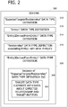
- the exemplary schema 302 includes several data type definitions including an ExpectedTargetofRelationship data type definition 310 (e.g., a target data type definition), an Entity 1 data type definition 312, an Entity2DerivedFromEntity1 data type definition 314, a Relationship data type definition 316, and an Entity3DerivedFromEntity1 data type definition 308 (e.g., a reference data type definition).
- the Entity3DerivedFromEntity1 data type definition 308 includes an instance 306 of the ExpectedTargetofRelationship data type definition 310.
- Instance 306 includes target data type elements 304 having data about expected relationships and target entities.
- the target data type elements 304 include target data (e.g., regarding expected entities and relationships such as a reference to the Relationship data type definition 316) and are of the type defined by the ExpectedTargetofRelationship data type definition 310.
- the derived entities Entity 2 and Entity 3 represent specializations of Entity 1. For example, entity 1 corresponds to general hardware, Entity 2 corresponds to a chassis, Entity 3 corresponds to a rack, and the Relationship data type definition 316 represents "is contained by.”
- the instance 306 is located in a well-known or standardized location of the Entity3DerivedFromEntity1 data type definition 308.
- the instance 306 may be located in elements of the Entity3DerivedFromEntity1 data type definition 308 such as ⁇ xs:appInfo> or ⁇ xs:annotation>.
- the ⁇ xs:appInfo> and ⁇ xs:annotation> elements are standard, available elements within the Entity3DerivedFromEntity1 data type definition 308. Such elements are typically used for application-level documentation of XML code.
- the instance 306 may be stored in any portion of the Entity3DerivedFromEntity1 data type definition 308. Multiple instances may be declared within the ⁇ xs:appInfo> and ⁇ xs:annotation> elements.
- FIG. 1 and FIG. 2 represent a system for utilizing a pre-defined data type definition such as ExpectedTargetofRelationship data type definition 310 in the definition of a basic entity's data type declaration such as Entity3DerivedFromEntity1 data type definition 308.
- the instance 306 is therefore applicable to all instances of Entity3DerivedFromEntity1 data type definition 308.
- the referenceQName corresponds to the Relationship data type definition 316.
- the schema 302 is represented as a data structure stored on a computer-readable medium. Aspects of the invention include or are operable with data structures having any quantity and ordering of fields therein.
- the exemplary data structure in FIG. 2 comprises a first field for storing the Entity3DerivedFromEntity1 data type definition 308.
- the Entity3DerivedFromEntity1 data type definition 308 corresponds to a basic entity in the object model. A well-known location, within the Entity3DerivedFromEntity1 data type definition 308, stores an instance 306 of the ExpectedTargetofRelationship data type definition 310 in a second field in the data structure.
- the instance 306 comprises instances of one or more target data type elements 304 each describing one or more target entities expected to be associated with the basic entity through the specified relationships (e.g., via an instance of the Relationship data type definition 316).
- a computing device executes computer-executable instructions to instantiate the Entity3DerivedFromEntity1 data type definition 308 and the Relationship data type definition 316 to associate instances of basic entities with data types defined in the target data type elements 304. These instances correspond to the definitions in schema 302.
- an exemplary flow chart illustrates the insertion of expected target data within a reference data type definition.
- an explicit tag is defined for the expected targets of a reference or relationship.
- the tag and contents are placed in a well-known and standard location within the XML document (e.g., within the xs:annotation section of the XML document).
- Existing element or type definitions are referenced to specifically define the target elements and types for the general relationships of an entity. There may be an unlimited quantity of references to the target, or the quantity may be specified explicitly in one of the target data type elements.
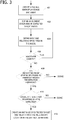
- an exemplary flow chart illustrates the insertion of expected target data within a reference data type definition to explicitly declare expected relationships between entities in a model.
- a tag is created in a markup language document (e.g., a schema type declaration such as in an XML document) at 401.
- An element describing an expected entity in the model is defined at 402.
- Basic and relationship entities in the model are defined at 404. For example, an expected quantity of one of the expected entities is defined. If there are additional entities to define at 406, the additional entities are defined at 404. If any of the defined entities cannot re-use general relationships inherited through the derivation hierarchy (e.g., specialization) at 408, then the process in an embodiment of the invention stops. Subtyping of predefined or existing relationships may need to occur to model the entities.
- At 410 If at least one of the defined entities can re-use the general relationships inherited through the derivation hierarchy at 408 (e.g., predefined or existing relationships), the process continues at 410.
- Predefined or existing relationships include, for example, "is contained by,” “is part of,” and “is included in.”
- hints should not be given regarding expected entities and relationships then the process in an embodiment of the invention stops. If hints should be given regarding expected entities and relationships at 410, an instance of the expected target is created and inserted into a well-known location in the entities' definitions at 412.
- Embodiments of the invention include a processor (not shown) configured to execute the computer-executable instructions. Upon execution, the computer-executable instructions implement aspects of the invention. Aspects of the invention may be implemented with any number and organization of such components or modules. For example, aspects of the invention are not limited to the specific computer-executable instructions or the specific components or modules illustrated in the figures and described herein. Other embodiments of the invention may include different computer-executable instructions or components having more or less functionality than illustrated and described herein.
- aspects of the invention include a method of explicitly declaring expected relationships between expected entities and a reference entity in a model.
- the reference entity has a reference data type definition associated therewith.
- the method includes:
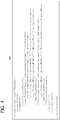
- an exemplary embodiment of an XML schema has an instance of expected target data embedded within a data type definition.
- the schema developer calls out what is expected to be inserted in a rack as well as the expected dependencies of the rack. This allows applications or tools to be customized for these expected elements.
- the rack typically contains one or more chassis, and likely not more than one monitor or keyboards (e.g., as instances of the "ChildRef' reference).
- the rack depends on a backup power source as an instance of the "RequiredElementRef' reference.
- the rack is declared as shown in FIG. 4 .
- the ChildRef reference corresponds to the Relationship data type definition 316 in FIG. 2 .
- the RackType corresponds to the Entity3DerivedFromEntity1 data type definition 308 in FIG. 2 .
- the ExpectedTargets corresponds to the instance 306 of "ExpectedTargetofRelationship" data type definition in FIG. 2 .
- the ChassisType corresponds to Entity2DerivedFromEntity1 data type definition 314 in FIG. 2 .
- the computer-executable instructions and components described herein constitute exemplary means for re-using a pre-defined data type definition associated with a reference entity to define target data types describing relationships of the reference entity.
- the targets of various generic relationships of the reference entity are highlighted within the declaration of the reference entity.
- the computer-executable instructions and components described herein further constitute exemplary means for defining one or more elements describing one or more entities expected to be associated with the reference entity.
- Examples of well known computing systems, environments, and/or configurations that may be suitable for use with aspects of the invention include, but are not limited to, personal computers, server computers, hand-held or laptop devices, multiprocessor systems, microprocessor-based systems, set top boxes, programmable consumer electronics, mobile telephones, network PCs, minicomputers, mainframe computers, distributed computing environments that include any of the above systems or devices, and the like.
- a computer executes computer-executable instructions such as those illustrated in the figures and described herein to implement aspects of the invention.
Description
- Software and non-software systems such as business processes and organizational structures may be modeled using currently available modeling languages. There are numerous general-purpose modeling languages that include a graphical notation to create an abstract model of the systems. The models may be serialized using markup languages such as the eXtensible Markup Language (XML), the Unified Modeling Language (UML), the Standard Generalized Markup Language (SGML), or the like.
- The abstract model may be viewed graphically by a user, or interpreted by software tools to determine the relationships between entities. For example, an asset manager program may access a model describing the hardware and software assets in a corporation to manage the configuration of the assets.
- When defining general models and ontologies, the user creates common types of entities and the relationships that connect the entities in the model. When defining leaf entities in the model, the user may want to highlight (e.g., for tooling and applications) specific general relationships that may exist among the entities. Some examples of general relationships are dependency and composition. In existing approaches, the relationships are defined by subtyping an existing relationship entity in the model and specifically restricting the referenced entities as targets within the subtype. With this approach, however, the representation of the model quickly becomes cluttered with numerous subtyped entities that add no semantics (e.g., no change in multiplicity, and no addition of properties or attributes other than to restrict the referenced entity). In addition, both the general and specifically highlighted relationships between the entities must be retained in the model. The existing approaches to declaring relationships among entities in a model result in highly complex, cluttered models that are difficult to interpret and that add no semantics to the model.
- Rather than declaring the expected targets in the model, another existing approach is to update each application that interprets models with the information about expected targets of general relationships. With this approach, however, each application has to be updated each time there is a change to the expected targets.
US 6 418 448 B1 discloses a mechanism in Extensible Markup Language (XML) and Resource Description Framework (RDF) for representing and navigating higher level specifications for data/metadata and for constructing arbitrary types by SQL queries with embedded method interfaces. These object SQL queries apply uniformly to one or more object relational databases over the web to manipulate data and to construct further XML/RDF documents for navigation and inspection. This way, a paradigm for navigation through Uniform Resource Identifiers with in XML/RDF documents and querying one or more object relational schema components identified by Uniform Resource Identifiers over the web will evolve.
It is therefore the object of the present invention to provide an improved method of explicitly declaring expected relationships between expected entities and a reference entity in a model, a corresponding system and a corresponding computer-readable medium.
This object is solved by the subject matter of the independent claims.
Preferred embodiments are defined by the dependent claims. - Embodiments of the invention describe expected entity relationships in a model representing objects in a system. In an embodiment, the invention includes the explicit declaration of expected, but not required, relationships between the entities in the model. Existing data type definitions for entities in the model are reused and not specialized. A target data type is defined to include data about entities expected to be related to a reference entity, and by what relationships. Instances of the target data type definition are included within the data type definition of the reference entity to relate the expected target entities with the reference entity.
- This summary is provided to introduce a selection of concepts in a simplified form that are further described below in the Detailed Description. This Summary is not intended to identify key features or essential features of the claimed subject matter, nor is it intended to be used as an aid in determining the scope of the claimed subject matter.
- Other features will be in part apparent and in part pointed out hereinafter.
-
FIG. 1 is an exemplary block diagram illustrating transfer of a ,markup language document from a data source to a data receiver. -
FIG. 2 is an exemplary block diagram illustrating a schema having an instance of a target data type definition embedded within the data type definition of a reference entity. -
FIG. 3 is an exemplary flow chart illustrating the insertion of expected target data within a reference data type definition. -
FIG. 4 is an exemplary embodiment of an XML schema having expected target data embedded within another data type definition. - Corresponding reference characters indicate corresponding parts throughout the drawings.
- Embodiments of the invention are directed to explicitly declaring expected relationships in a model of objects or processes as represented by a schema type declaration. This information is useful for tooling and applications to optimize their performance and display. For example, a model represents a rack and its hardware components and dependencies. An entity (e.g., a basic entity or other reference entity) corresponding to the rack is represented by a class definition in the Unified Modeling Language (UML) or an element definition in the eXtensible Markup Language (XML). This entity may have several expected, but not required, relationships between itself and other basic entities. For example, the rack may be dependent on an external cooling component. Rather than subtyping a dependency relationship entity to specialize it for the rack and cooling component, the expected relationships are suggested in the definition of the basic entity (e.g., as metadata). This approach conveys the expected relationships without cluttering and confusing the model.
- The model may be serialized or otherwise represented by a markup language such as XML. While some aspects of the invention are described herein with reference to XML, aspects of the invention are operable with any form of text-based markup language or UML-based graphical rendering.
- The expected relationships appear in the markup language serialization of the model. For example, an instance of the <ExpectedTargets> element is located within, for example, the <xs:appinfo> tags (e.g., within the <xs:annotation> tags) of a type or element declaration. Using this approach, the expected relationships are declared within the type or element declaration while the general relationships are used directly without redefinition.
- Referring next to
FIG. 1 , an exemplary block diagram illustrates transfer of adocument 202 from adata source 204 to adata receiver 206 over one ormore networks networks document 202 may be a meta-language document, a markup language document, a meta-markup language document, a tag-based language document, or other graphical or text-based model description. - Markup languages provide a uniform method for exchanging data in an open, text-based format. Markup languages include a set of codes (e.g., tags) conveying data to enable documents such as
document 202 and other files to be platform-independent and highly portable between applications. Elements in a markup language are structural constructs that include a start tag, an end or close tag, and information, content, or other data included between or within the tags. A start tag is formatted as <tagname> and an end tag is formatted as </tagname>. Indocument 202, start and end tags may be nested within other start and end tags. Each element forms a node in this structure, and potentially has child, leaf, or branch nodes. The child nodes represent any elements that occur between the start and end tags of the parent node. - The structure of the
document 202 is defined by aschema 212, schema document, or similar structure. Theschema 212 defines the legal building blocks of the document including element declarations, child elements, attributes, data types, data values for the elements, default and fixed values for elements and attributes, and other properties and values. For example, standard data types such as strings, dates, date times, durations, time zones, decimals, numerical values, integers, and the like may be used in a schema within type declarations. - While markup languages support various standard data types, further data types (e.g., both simple and complex data types) may be defined by the programmer in the schema. To use a data type, an element of that type is declared in the
document 202 and then instantiated. Instantiations of elements of given data types may be assigned values when created and may subsequently be updated or removed. - In the example of
FIG. 1 , thedata source 204 provides data to adata receiver 206. The data is embedded in thedocument 202.Document 202 is formatted in accordance with standardized markup language syntax, and also conforms to theschema 212.Data receiver 206 parses and interprets data in thedocument 202 with reference toschema 212. Theschema 212 corresponds to a model representing objects in a system. -
Data receiver 206 receivesdocument 202 and while parsing and interpreting thedocument 202 may encounter one or more instances of elements defined within thedocument 202 or in theschema 212. In general,data receiver 206 references theschema 212 to identify data elements and type definitions corresponding to the encountered instances. Ifdata receiver 206 finds that the elements are not defined or otherwise specified inschema 212, thedata receiver 206 may show an error. If the document element is found inschema 212, thedata receiver 206 uses information obtained from theschema 212 while parsing or interpreting thedocument 202. - While
schema 212 is shown to be stored in amemory area 214 accessible by or associated withdata source 204, theschema 212 or a copy thereof is also accessibly by the data receiver 206 (e.g., stored in a memory area accessible by the data receiver 206). - Aspects of the invention may be implemented with a general purpose computing device in the form of a computer. Generally, the data processors of the computer are programmed by means of instructions stored at different times in the various computer-readable storage media of the computer. Embodiments of the invention may be described and implemented in the general context of computer-executable instructions, such as program modules, executed by one or more computers or other devices. The computing device has access to or is associated with a computer-readable media such as a
memory area 214 storing, for example, theschema 212. Computer readable media, which include both volatile and nonvolatile media, removable and non-removable media, may be any available medium that may be accessed by the service. By way of example and not limitation, computer readable media comprise computer storage media and communication media. Computer storage media include volatile and nonvolatile, removable and non-removable media implemented in any method or technology for storage of information such as computer readable instructions, data structures, program modules or other data. For example, computer storage media include RAM, ROM, EEPROM, flash memory or other memory technology, CD-ROM, digital versatile disks (DVD) or other optical disk storage, magnetic cassettes, magnetic tape, magnetic disk storage or other magnetic storage devices, or any other medium that may be used to store the desired information and that may be accessed by the computing device. Communication media typically embody computer readable instructions, data structures, program modules, or other data in a modulated data signal such as a carrier wave or other transport mechanism and include any information delivery media. Those skilled in the art are familiar with the modulated data signal, which has one or more of its characteristics set or changed in such a manner as to encode information in the signal. Wired media, such as a wired network or direct-wired connection, and wireless media, such as acoustic, RF, infrared, and other wireless media, are examples of communication media. Combinations of any of the above are also included within the scope of computer readable media. - Referring next to
FIG. 2 , a block diagram illustrates anexemplary schema 302. Theexemplary schema 302 includes several data type definitions including an ExpectedTargetofRelationship data type definition 310 (e.g., a target data type definition), anEntity 1data type definition 312, an Entity2DerivedFromEntity1data type definition 314, a Relationshipdata type definition 316, and an Entity3DerivedFromEntity1 data type definition 308 (e.g., a reference data type definition). The Entity3DerivedFromEntity1data type definition 308 includes aninstance 306 of the ExpectedTargetofRelationshipdata type definition 310.Instance 306 includes targetdata type elements 304 having data about expected relationships and target entities. The targetdata type elements 304 include target data (e.g., regarding expected entities and relationships such as a reference to the Relationship data type definition 316) and are of the type defined by the ExpectedTargetofRelationshipdata type definition 310. The derived entities Entity 2 and Entity 3 represent specializations ofEntity 1. For example,entity 1 corresponds to general hardware, Entity 2 corresponds to a chassis, Entity 3 corresponds to a rack, and the Relationshipdata type definition 316 represents "is contained by." - The
instance 306 is located in a well-known or standardized location of the Entity3DerivedFromEntity1data type definition 308. For example, theinstance 306 may be located in elements of the Entity3DerivedFromEntity1data type definition 308 such as <xs:appInfo> or <xs:annotation>. In general, the <xs:appInfo> and <xs:annotation> elements are standard, available elements within the Entity3DerivedFromEntity1data type definition 308. Such elements are typically used for application-level documentation of XML code. However, theinstance 306 may be stored in any portion of the Entity3DerivedFromEntity1data type definition 308. Multiple instances may be declared within the <xs:appInfo> and <xs:annotation> elements. - In general,
FIG. 1 andFIG. 2 represent a system for utilizing a pre-defined data type definition such as ExpectedTargetofRelationshipdata type definition 310 in the definition of a basic entity's data type declaration such as Entity3DerivedFromEntity1data type definition 308. Theinstance 306 is therefore applicable to all instances of Entity3DerivedFromEntity1data type definition 308. - An example of an XML definition of the
instance 306 is shown below.
      <xs:element name="ExpectedTargets">
        <xs:annotation>
             <xs:documentation>An element of this type is placed in xs:appinfo,
      to allow the definition of the "expected" targets (elements or types) of the
      general, inherited references such as dependency or composition. In
      addition, the expected number of instances of the reference, to the target, can
      be indicated (if not specified, there may be any number of instances). An
      example would be to indicate that a Rack contains one or more chassis (i.e.,
      that the ChildRef element is used and expected to reference multiple
      instances of ChassisType) and requires a backup power source (i.e., that the
      RequiredElementRef element is used and expected to reference one instance
      of PowerSourceType).</xs:documentation>
        </xs: annotation>
        <xs:complexType
             <xs : sequence>
               <xs:element name="TargetDetails" type="TargetDetailsType"
      minOccurs="0" maxOccurs="unbounded"/>
             </xs: sequence>
        </xs:complexType>
      </xs:element>
      <xs:complexType name="TargetDetailsType">
        <xs:annotation>
             <xs:documentation>An entity that contains (as child elements) the
      targets of the reference defined by the referenceQName attribute.
      </xs: documentation>
        </xs: annotation>
        <xs : sequence>
             <xs:element name="TargetQName" minOccurs="0"
      maxOccurs="unbounded">
               <xs:annotation>
                   <xs:documentation>The specific target entity (type or
      element) and expectedNumber of references to that
      entity.</xs: documentation>
               </xs: annotation>
               <xs:complexType>
                   <xs:simpleContent>
                      <xs:extension base="xs:QName">
                      <xs:attribute name="expectedNumber"
      type="xs:unsignedByte" use="optional"/>
                      </xs:extension>
                   </xs:simpleContent>
               </xs:complexType>
             </xs:element>
        </xs: sequence>
        <xs:attribute name="referenceQName" type="xs:QName"
      use="required"/>
      </xs:complexType>
- creating an expected targets tag in a markup language schema type declaration;
- defining one or more elements describing one or more expected entities in the model;
- identifying a predefined entity relationship;
- associating the expected targets tag with the defined elements and the identified, predefined entity relationship; and
- locating the expected targets tag and associated elements and entity relationship in the reference data type definition of the reference entity to declare a relationship between the expected entities and the reference entity.
- identifying a data type definition from the markup language schema, said data type definition corresponding to a reference entity in the model;
- defining one or more elements describing one or more entities expected to be associated with the reference entity;
- identifying predefined entity relationships for use in associating the expected entities with the reference entity, said expected entities having a target data type definition associated therewith, said reference entity having a reference data type definition associated therewith;
- associating the defined elements and the defined relationships with a tag;
- inserting the tag with the associated elements and relationships into an instance of the target data type definition; and
- locating the instance of the target data type definition in the reference data type definition to relate the expected entities with the reference entity in the model.
Claims (7)
- A method of explicitly declaring relationships between entities and a reference entity in a model interpreted by an application, wherein the model is serialized or represented by a markup language such as extensible Markup Language, XML, Unified Modeling Language, UML, or Standard Generalized Markup Language, SGML, said reference entity has a reference data type definition (308) associated therewith, and said entities having a target data type definition associated therewith, wherein:a targets tag, defined for one or more entities, is created in a markup language schema type declaration (302);the targets tag is associated with one or more defined elements (304) describing said one or more entities in the model and a predefined entity relationship (316);the targets tag with the associated elements (304) and the relationship (316) is inserted into an instance (306) of the target data type definition;the instance of the target data type definition is located in the reference data type definition (308) of the reference entity to relate the entities and the reference entity in the model; andsaid method comprising:
interpreting, by a processor configured to execute computer-executable instructions, the reference data type definition (308) by referring to a markup language schema (212) stored in a memory area (214), the markup language schema corresponding to the model. - The method of claim 1, wherein the one or more element represents a quantity of one of the entities.
- The method of claim 1, wherein the targets tag is in an extensible Markup Language, XML, document.
- The method of claim 1, wherein the one or more entities in the model represent objects in a system.
- The method of claim 1, further comprising displaying the model in graphical or textual form.
- A system comprising a memory area and a processor configured to execute computer-executable instructions for performing the method of claim 1.
- The system of claim 6, wherein the processor is further configured to execute computer-executable instructions for displaying the reference data type definition in the model, or wherein the memory area stores a markup language schema in a format conforming to the Unified Modeling Language, UML.
Applications Claiming Priority (2)
| Application Number | Priority Date | Filing Date | Title |
|---|---|---|---|
| US11/738,194 US7765241B2 (en) | 2007-04-20 | 2007-04-20 | Describing expected entity relationships in a model |
| PCT/US2008/057746 WO2008130768A1 (en) | 2007-04-20 | 2008-03-20 | Describing expected entity relationships in a model |
Publications (3)
| Publication Number | Publication Date |
|---|---|
| EP2149094A1 EP2149094A1 (en) | 2010-02-03 |
| EP2149094A4 EP2149094A4 (en) | 2016-08-03 |
| EP2149094B1 true EP2149094B1 (en) | 2020-06-17 |
Family
ID=39873294
Family Applications (1)
| Application Number | Title | Priority Date | Filing Date |
|---|---|---|---|
| EP08744155.6A Active EP2149094B1 (en) | 2007-04-20 | 2008-03-20 | Describing expected entity relationships in a model |
Country Status (5)
| Country | Link |
|---|---|
| US (1) | US7765241B2 (en) |
| EP (1) | EP2149094B1 (en) |
| JP (1) | JP2010525452A (en) |
| CN (1) | CN101663663B (en) |
| WO (1) | WO2008130768A1 (en) |
Families Citing this family (8)
| Publication number | Priority date | Publication date | Assignee | Title |
|---|---|---|---|---|
| US20080184277A1 (en) * | 2007-01-26 | 2008-07-31 | Microsoft Corporation | Systems management policy validation, distribution and enactment |
| US20090271439A1 (en) * | 2008-04-23 | 2009-10-29 | John Hack | Systems to implement business processes in computing environment |
| CN103823842B (en) * | 2014-01-20 | 2018-04-20 | 中国建设银行股份有限公司 | A kind of ERWIN prototype softwares update method and device |
| US9613067B2 (en) | 2014-01-24 | 2017-04-04 | International Business Machines Corporation | Defining and transforming entity relationship-XML hybrid data models |
| CN105278936B (en) * | 2014-06-25 | 2018-06-22 | 成都普中软件有限公司 | A kind of common software modeling method based on software meta-model construction software model |
| CN105204834B (en) * | 2014-06-25 | 2018-06-29 | 成都普中软件有限公司 | A kind of visual software modeling editing machine for constructing software model |
| US11567911B2 (en) * | 2014-12-19 | 2023-01-31 | Sergey Anatol'evich GORISHNIY | System and method for management of functionally linked data |
| CN107832044B (en) * | 2017-11-16 | 2019-02-19 | 安徽修武工业技术有限公司 | A kind of common software modeling method based on software meta-model construction |
Family Cites Families (39)
| Publication number | Priority date | Publication date | Assignee | Title |
|---|---|---|---|---|
| US6711585B1 (en) * | 1999-06-15 | 2004-03-23 | Kanisa Inc. | System and method for implementing a knowledge management system |
| US7181438B1 (en) * | 1999-07-21 | 2007-02-20 | Alberti Anemometer, Llc | Database access system |
| US7134072B1 (en) * | 1999-10-13 | 2006-11-07 | Microsoft Corporation | Methods and systems for processing XML documents |
| US6418448B1 (en) * | 1999-12-06 | 2002-07-09 | Shyam Sundar Sarkar | Method and apparatus for processing markup language specifications for data and metadata used inside multiple related internet documents to navigate, query and manipulate information from a plurality of object relational databases over the web |
| US6675355B1 (en) * | 2000-03-16 | 2004-01-06 | Autodesk, Inc. | Redline extensible markup language (XML) schema |
| GB0011426D0 (en) * | 2000-05-11 | 2000-06-28 | Charteris Limited | A method for transforming documents written in different XML-based languages |
| US6704776B1 (en) * | 2000-06-30 | 2004-03-09 | Webtv Networks, Inc. | Selecting attribute based content for server applications |
| US6859217B2 (en) * | 2000-07-19 | 2005-02-22 | Microsoft Corporation | System and method to display and manage data within hierarchies and polyarchies of information |
| US6973640B2 (en) * | 2000-10-04 | 2005-12-06 | Bea Systems, Inc. | System and method for computer code generation |
| KR100427603B1 (en) | 2000-12-01 | 2004-04-30 | (주)코어로직스 | Method for constructing structure for categorizing data |
| US7146399B2 (en) * | 2001-05-25 | 2006-12-05 | 2006 Trident Company | Run-time architecture for enterprise integration with transformation generation |
| US7099885B2 (en) * | 2001-05-25 | 2006-08-29 | Unicorn Solutions | Method and system for collaborative ontology modeling |
| US6848033B2 (en) * | 2001-06-07 | 2005-01-25 | Hewlett-Packard Development Company, L.P. | Method of memory management in a multi-threaded environment and program storage device |
| US20040230572A1 (en) * | 2001-06-22 | 2004-11-18 | Nosa Omoigui | System and method for semantic knowledge retrieval, management, capture, sharing, discovery, delivery and presentation |
| CA2354443A1 (en) * | 2001-07-31 | 2003-01-31 | Ibm Canada Limited-Ibm Canada Limitee | Method and system for visually constructing xml schemas using an object-oriented model |
| US7089533B2 (en) * | 2001-08-01 | 2006-08-08 | Oic Acquisition I Corp | Method and system for mapping between markup language document and an object model |
| US7894083B2 (en) * | 2001-09-14 | 2011-02-22 | Canon Kabushiki Kaisha | Print control with interfaces provided in correspondence with printing methods |
| AU2002334721B2 (en) * | 2001-09-28 | 2008-10-23 | Oracle International Corporation | An index structure to access hierarchical data in a relational database system |
| US6826568B2 (en) * | 2001-12-20 | 2004-11-30 | Microsoft Corporation | Methods and system for model matching |
| US7640267B2 (en) * | 2002-11-20 | 2009-12-29 | Radar Networks, Inc. | Methods and systems for managing entities in a computing device using semantic objects |
| JP2006507580A (en) | 2002-11-21 | 2006-03-02 | ノキア コーポレイション | Method and apparatus for defining an object enabling setting of a device management tree for a mobile communication device |
| JP2004199577A (en) * | 2002-12-20 | 2004-07-15 | Hitachi Ltd | Integrated editing method of setting file and setting file integrated base |
| US7043487B2 (en) * | 2002-12-28 | 2006-05-09 | International Business Machines Corporation | Method for storing XML documents in a relational database system while exploiting XML schema |
| US7617160B1 (en) * | 2003-02-05 | 2009-11-10 | Michael I. Grove | Choice-based relationship system (CRS) |
| US7120618B2 (en) * | 2003-02-28 | 2006-10-10 | Microsoft Corporation | System and method for defining and using subclasses declaratively within markup |
| CA2432658C (en) * | 2003-06-17 | 2008-04-01 | Ibm Canada Limited - Ibm Canada Limitee | Simple types in xml schema complex types |
| US20040261016A1 (en) * | 2003-06-20 | 2004-12-23 | Miavia, Inc. | System and method for associating structured and manually selected annotations with electronic document contents |
| US20040267764A1 (en) * | 2003-06-25 | 2004-12-30 | Rothman Michael A | Method to efficiently describe configuration settings in a standardized format |
| US7447677B2 (en) * | 2003-06-27 | 2008-11-04 | Microsoft Corporation | System and method for enabling client applications to interactively obtain and present taxonomy information |
| US7403956B2 (en) * | 2003-08-29 | 2008-07-22 | Microsoft Corporation | Relational schema format |
| US8380715B2 (en) * | 2004-06-04 | 2013-02-19 | Vital Source Technologies, Inc. | System, method and computer program product for managing and organizing pieces of content |
| US7266548B2 (en) * | 2004-06-30 | 2007-09-04 | Microsoft Corporation | Automated taxonomy generation |
| US20060010369A1 (en) * | 2004-07-07 | 2006-01-12 | Stephan Naundorf | Enhancements of data types in XML schema |
| US7496593B2 (en) * | 2004-09-03 | 2009-02-24 | Biowisdom Limited | Creating a multi-relational ontology having a predetermined structure |
| ATE510259T1 (en) * | 2005-01-31 | 2011-06-15 | Ontoprise Gmbh | MAPPING WEB SERVICES TO ONTOLOGIES |
| JP4450746B2 (en) | 2005-03-01 | 2010-04-14 | 富士通周辺機株式会社 | Terminal device management system, terminal device management method, and computer program |
| EP1899802A2 (en) * | 2005-07-05 | 2008-03-19 | Encapsa Technologies Inc. | Encapsulating information in a database for use in a communication system |
| CA2545232A1 (en) * | 2005-07-29 | 2007-01-29 | Cognos Incorporated | Method and system for creating a taxonomy from business-oriented metadata content |
| US7653622B2 (en) * | 2005-07-29 | 2010-01-26 | Microsoft Corporation | Automated content categorization |
-
2007
- 2007-04-20 US US11/738,194 patent/US7765241B2/en not_active Expired - Fee Related
-
2008
- 2008-03-20 CN CN2008800125211A patent/CN101663663B/en not_active Expired - Fee Related
- 2008-03-20 EP EP08744155.6A patent/EP2149094B1/en active Active
- 2008-03-20 JP JP2010504141A patent/JP2010525452A/en active Pending
- 2008-03-20 WO PCT/US2008/057746 patent/WO2008130768A1/en active Application Filing
Non-Patent Citations (1)
| Title |
|---|
| None * |
Also Published As
| Publication number | Publication date |
|---|---|
| JP2010525452A (en) | 2010-07-22 |
| WO2008130768A1 (en) | 2008-10-30 |
| US7765241B2 (en) | 2010-07-27 |
| CN101663663A (en) | 2010-03-03 |
| US20080263085A1 (en) | 2008-10-23 |
| CN101663663B (en) | 2013-02-13 |
| EP2149094A1 (en) | 2010-02-03 |
| EP2149094A4 (en) | 2016-08-03 |
Similar Documents
| Publication | Publication Date | Title |
|---|---|---|
| EP2149094B1 (en) | Describing expected entity relationships in a model | |
| US7752224B2 (en) | Programmability for XML data store for documents | |
| US7543268B2 (en) | Development environment for developing applications using a metamodel and a metadata API | |
| US8438190B2 (en) | Generating web services from business intelligence queries | |
| US6915304B2 (en) | System and method for converting an XML data structure into a relational database | |
| US8255888B2 (en) | API derivation and XML schema derivation for developing applications | |
| EP1683009B1 (en) | Systems and methods for configuring software | |
| US7716164B2 (en) | Layout information for data element | |
| US20050071805A1 (en) | Developing applications using a metamodel | |
| EP1793320B1 (en) | Modeling a data element | |
| US7644095B2 (en) | Method and system for compound document assembly with domain-specific rules processing and generic schema mapping | |
| US8275775B2 (en) | Providing web services from business intelligence queries | |
| US20080250394A1 (en) | Synchronizing external documentation with code development | |
| US20060277452A1 (en) | Structuring data for presentation documents | |
| US20060190815A1 (en) | Structuring data for word processing documents | |
| US9495475B2 (en) | Method of representing an XML schema definition and data within a relational database management system using a reusable custom-defined nestable compound data type | |
| KR101311123B1 (en) | Programmability for xml data store for documents | |
| WO2002059773A1 (en) | Modular distributed mobile data applications | |
| US8407235B2 (en) | Exposing and using metadata and meta-metadata | |
| US20090313281A1 (en) | Mechanisms to persist hierarchical object relations | |
| US10489024B2 (en) | UI rendering based on adaptive label text infrastructure | |
| EP1775663A2 (en) | Information management system and information display device | |
| Pikus et al. | Semi-automatic ontology-driven development documentation: generating documents from RDF data and DITA templates | |
| Vohra | Pro XML Development with Java Technology | |
| Pardillo et al. | RETRACTED: Model-driven development of OLAP metadata for relational data warehouses |
Legal Events
| Date | Code | Title | Description |
|---|---|---|---|
| PUAI | Public reference made under article 153(3) epc to a published international application that has entered the european phase |
Free format text: ORIGINAL CODE: 0009012 |
|
| 17P | Request for examination filed |
Effective date: 20091113 |
|
| AK | Designated contracting states |
Kind code of ref document: A1 Designated state(s): AT BE BG CH CY CZ DE DK EE ES FI FR GB GR HR HU IE IS IT LI LT LU LV MC MT NL NO PL PT RO SE SI SK TR |
|
| AX | Request for extension of the european patent |
Extension state: AL BA MK RS |
|
| DAX | Request for extension of the european patent (deleted) | ||
| RAP1 | Party data changed (applicant data changed or rights of an application transferred) |
Owner name: MICROSOFT TECHNOLOGY LICENSING, LLC |
|
| RA4 | Supplementary search report drawn up and despatched (corrected) |
Effective date: 20160701 |
|
| RIC1 | Information provided on ipc code assigned before grant |
Ipc: G06F 17/30 20060101ALI20160627BHEP Ipc: G06F 17/00 20060101AFI20160627BHEP |
|
| STAA | Information on the status of an ep patent application or granted ep patent |
Free format text: STATUS: EXAMINATION IS IN PROGRESS |
|
| 17Q | First examination report despatched |
Effective date: 20181218 |
|
| RIC1 | Information provided on ipc code assigned before grant |
Ipc: G06F 17/22 20060101ALI20191203BHEP Ipc: G06F 17/27 20060101ALI20191203BHEP Ipc: G06F 16/28 20190101AFI20191203BHEP |
|
| GRAP | Despatch of communication of intention to grant a patent |
Free format text: ORIGINAL CODE: EPIDOSNIGR1 |
|
| REG | Reference to a national code |
Ref country code: DE Ref legal event code: R079 Ref document number: 602008062858 Country of ref document: DE Free format text: PREVIOUS MAIN CLASS: G06F0017000000 Ipc: G06F0016280000 |
|
| STAA | Information on the status of an ep patent application or granted ep patent |
Free format text: STATUS: GRANT OF PATENT IS INTENDED |
|
| INTG | Intention to grant announced |
Effective date: 20200115 |
|
| RIC1 | Information provided on ipc code assigned before grant |
Ipc: G06F 40/20 20200101ALI20200114BHEP Ipc: G06F 16/28 20190101AFI20200114BHEP Ipc: G06F 40/12 20200101ALI20200114BHEP |
|
| GRAS | Grant fee paid |
Free format text: ORIGINAL CODE: EPIDOSNIGR3 |
|
| GRAA | (expected) grant |
Free format text: ORIGINAL CODE: 0009210 |
|
| STAA | Information on the status of an ep patent application or granted ep patent |
Free format text: STATUS: THE PATENT HAS BEEN GRANTED |
|
| AK | Designated contracting states |
Kind code of ref document: B1 Designated state(s): AT BE BG CH CY CZ DE DK EE ES FI FR GB GR HR HU IE IS IT LI LT LU LV MC MT NL NO PL PT RO SE SI SK TR |
|
| REG | Reference to a national code |
Ref country code: GB Ref legal event code: FG4D |
|
| REG | Reference to a national code |
Ref country code: CH Ref legal event code: EP |
|
| REG | Reference to a national code |
Ref country code: IE Ref legal event code: FG4D |
|
| REG | Reference to a national code |
Ref country code: DE Ref legal event code: R096 Ref document number: 602008062858 Country of ref document: DE |
|
| REG | Reference to a national code |
Ref country code: AT Ref legal event code: REF Ref document number: 1282209 Country of ref document: AT Kind code of ref document: T Effective date: 20200715 |
|
| PG25 | Lapsed in a contracting state [announced via postgrant information from national office to epo] |
Ref country code: LT Free format text: LAPSE BECAUSE OF FAILURE TO SUBMIT A TRANSLATION OF THE DESCRIPTION OR TO PAY THE FEE WITHIN THE PRESCRIBED TIME-LIMIT Effective date: 20200617 Ref country code: NO Free format text: LAPSE BECAUSE OF FAILURE TO SUBMIT A TRANSLATION OF THE DESCRIPTION OR TO PAY THE FEE WITHIN THE PRESCRIBED TIME-LIMIT Effective date: 20200917 Ref country code: GR Free format text: LAPSE BECAUSE OF FAILURE TO SUBMIT A TRANSLATION OF THE DESCRIPTION OR TO PAY THE FEE WITHIN THE PRESCRIBED TIME-LIMIT Effective date: 20200918 Ref country code: SE Free format text: LAPSE BECAUSE OF FAILURE TO SUBMIT A TRANSLATION OF THE DESCRIPTION OR TO PAY THE FEE WITHIN THE PRESCRIBED TIME-LIMIT Effective date: 20200617 Ref country code: FI Free format text: LAPSE BECAUSE OF FAILURE TO SUBMIT A TRANSLATION OF THE DESCRIPTION OR TO PAY THE FEE WITHIN THE PRESCRIBED TIME-LIMIT Effective date: 20200617 |
|
| REG | Reference to a national code |
Ref country code: LT Ref legal event code: MG4D |
|
| REG | Reference to a national code |
Ref country code: NL Ref legal event code: MP Effective date: 20200617 |
|
| PG25 | Lapsed in a contracting state [announced via postgrant information from national office to epo] |
Ref country code: BG Free format text: LAPSE BECAUSE OF FAILURE TO SUBMIT A TRANSLATION OF THE DESCRIPTION OR TO PAY THE FEE WITHIN THE PRESCRIBED TIME-LIMIT Effective date: 20200917 Ref country code: HR Free format text: LAPSE BECAUSE OF FAILURE TO SUBMIT A TRANSLATION OF THE DESCRIPTION OR TO PAY THE FEE WITHIN THE PRESCRIBED TIME-LIMIT Effective date: 20200617 Ref country code: LV Free format text: LAPSE BECAUSE OF FAILURE TO SUBMIT A TRANSLATION OF THE DESCRIPTION OR TO PAY THE FEE WITHIN THE PRESCRIBED TIME-LIMIT Effective date: 20200617 |
|
| REG | Reference to a national code |
Ref country code: AT Ref legal event code: MK05 Ref document number: 1282209 Country of ref document: AT Kind code of ref document: T Effective date: 20200617 |
|
| PG25 | Lapsed in a contracting state [announced via postgrant information from national office to epo] |
Ref country code: NL Free format text: LAPSE BECAUSE OF FAILURE TO SUBMIT A TRANSLATION OF THE DESCRIPTION OR TO PAY THE FEE WITHIN THE PRESCRIBED TIME-LIMIT Effective date: 20200617 |
|
| PG25 | Lapsed in a contracting state [announced via postgrant information from national office to epo] |
Ref country code: IT Free format text: LAPSE BECAUSE OF FAILURE TO SUBMIT A TRANSLATION OF THE DESCRIPTION OR TO PAY THE FEE WITHIN THE PRESCRIBED TIME-LIMIT Effective date: 20200617 Ref country code: RO Free format text: LAPSE BECAUSE OF FAILURE TO SUBMIT A TRANSLATION OF THE DESCRIPTION OR TO PAY THE FEE WITHIN THE PRESCRIBED TIME-LIMIT Effective date: 20200617 Ref country code: CZ Free format text: LAPSE BECAUSE OF FAILURE TO SUBMIT A TRANSLATION OF THE DESCRIPTION OR TO PAY THE FEE WITHIN THE PRESCRIBED TIME-LIMIT Effective date: 20200617 Ref country code: ES Free format text: LAPSE BECAUSE OF FAILURE TO SUBMIT A TRANSLATION OF THE DESCRIPTION OR TO PAY THE FEE WITHIN THE PRESCRIBED TIME-LIMIT Effective date: 20200617 Ref country code: AT Free format text: LAPSE BECAUSE OF FAILURE TO SUBMIT A TRANSLATION OF THE DESCRIPTION OR TO PAY THE FEE WITHIN THE PRESCRIBED TIME-LIMIT Effective date: 20200617 Ref country code: PT Free format text: LAPSE BECAUSE OF FAILURE TO SUBMIT A TRANSLATION OF THE DESCRIPTION OR TO PAY THE FEE WITHIN THE PRESCRIBED TIME-LIMIT Effective date: 20201019 Ref country code: EE Free format text: LAPSE BECAUSE OF FAILURE TO SUBMIT A TRANSLATION OF THE DESCRIPTION OR TO PAY THE FEE WITHIN THE PRESCRIBED TIME-LIMIT Effective date: 20200617 |
|
| PG25 | Lapsed in a contracting state [announced via postgrant information from national office to epo] |
Ref country code: SK Free format text: LAPSE BECAUSE OF FAILURE TO SUBMIT A TRANSLATION OF THE DESCRIPTION OR TO PAY THE FEE WITHIN THE PRESCRIBED TIME-LIMIT Effective date: 20200617 Ref country code: PL Free format text: LAPSE BECAUSE OF FAILURE TO SUBMIT A TRANSLATION OF THE DESCRIPTION OR TO PAY THE FEE WITHIN THE PRESCRIBED TIME-LIMIT Effective date: 20200617 Ref country code: IS Free format text: LAPSE BECAUSE OF FAILURE TO SUBMIT A TRANSLATION OF THE DESCRIPTION OR TO PAY THE FEE WITHIN THE PRESCRIBED TIME-LIMIT Effective date: 20201017 |
|
| REG | Reference to a national code |
Ref country code: DE Ref legal event code: R097 Ref document number: 602008062858 Country of ref document: DE |
|
| PLBE | No opposition filed within time limit |
Free format text: ORIGINAL CODE: 0009261 |
|
| STAA | Information on the status of an ep patent application or granted ep patent |
Free format text: STATUS: NO OPPOSITION FILED WITHIN TIME LIMIT |
|
| PG25 | Lapsed in a contracting state [announced via postgrant information from national office to epo] |
Ref country code: DK Free format text: LAPSE BECAUSE OF FAILURE TO SUBMIT A TRANSLATION OF THE DESCRIPTION OR TO PAY THE FEE WITHIN THE PRESCRIBED TIME-LIMIT Effective date: 20200617 |
|
| PGFP | Annual fee paid to national office [announced via postgrant information from national office to epo] |
Ref country code: FR Payment date: 20210210 Year of fee payment: 14 |
|
| 26N | No opposition filed |
Effective date: 20210318 |
|
| PG25 | Lapsed in a contracting state [announced via postgrant information from national office to epo] |
Ref country code: SI Free format text: LAPSE BECAUSE OF FAILURE TO SUBMIT A TRANSLATION OF THE DESCRIPTION OR TO PAY THE FEE WITHIN THE PRESCRIBED TIME-LIMIT Effective date: 20200617 |
|
| PGFP | Annual fee paid to national office [announced via postgrant information from national office to epo] |
Ref country code: GB Payment date: 20210310 Year of fee payment: 14 Ref country code: DE Payment date: 20210310 Year of fee payment: 14 |
|
| PG25 | Lapsed in a contracting state [announced via postgrant information from national office to epo] |
Ref country code: MC Free format text: LAPSE BECAUSE OF FAILURE TO SUBMIT A TRANSLATION OF THE DESCRIPTION OR TO PAY THE FEE WITHIN THE PRESCRIBED TIME-LIMIT Effective date: 20200617 |
|
| REG | Reference to a national code |
Ref country code: CH Ref legal event code: PL |
|
| REG | Reference to a national code |
Ref country code: BE Ref legal event code: MM Effective date: 20210331 |
|
| PG25 | Lapsed in a contracting state [announced via postgrant information from national office to epo] |
Ref country code: LI Free format text: LAPSE BECAUSE OF NON-PAYMENT OF DUE FEES Effective date: 20210331 Ref country code: LU Free format text: LAPSE BECAUSE OF NON-PAYMENT OF DUE FEES Effective date: 20210320 Ref country code: CH Free format text: LAPSE BECAUSE OF NON-PAYMENT OF DUE FEES Effective date: 20210331 Ref country code: IE Free format text: LAPSE BECAUSE OF NON-PAYMENT OF DUE FEES Effective date: 20210320 |
|
| PG25 | Lapsed in a contracting state [announced via postgrant information from national office to epo] |
Ref country code: BE Free format text: LAPSE BECAUSE OF NON-PAYMENT OF DUE FEES Effective date: 20210331 |
|
| REG | Reference to a national code |
Ref country code: DE Ref legal event code: R119 Ref document number: 602008062858 Country of ref document: DE |
|
| GBPC | Gb: european patent ceased through non-payment of renewal fee |
Effective date: 20220320 |
|
| PG25 | Lapsed in a contracting state [announced via postgrant information from national office to epo] |
Ref country code: GB Free format text: LAPSE BECAUSE OF NON-PAYMENT OF DUE FEES Effective date: 20220320 Ref country code: FR Free format text: LAPSE BECAUSE OF NON-PAYMENT OF DUE FEES Effective date: 20220331 Ref country code: DE Free format text: LAPSE BECAUSE OF NON-PAYMENT OF DUE FEES Effective date: 20221001 |
|
| PG25 | Lapsed in a contracting state [announced via postgrant information from national office to epo] |
Ref country code: HU Free format text: LAPSE BECAUSE OF FAILURE TO SUBMIT A TRANSLATION OF THE DESCRIPTION OR TO PAY THE FEE WITHIN THE PRESCRIBED TIME-LIMIT; INVALID AB INITIO Effective date: 20080320 Ref country code: CY Free format text: LAPSE BECAUSE OF FAILURE TO SUBMIT A TRANSLATION OF THE DESCRIPTION OR TO PAY THE FEE WITHIN THE PRESCRIBED TIME-LIMIT Effective date: 20200617 |
|
| P01 | Opt-out of the competence of the unified patent court (upc) registered |
Effective date: 20230505 |