EP2148606B1 - Rack handle member for a dishwasher - Google Patents
Rack handle member for a dishwasher Download PDFInfo
- Publication number
- EP2148606B1 EP2148606B1 EP08747311.2A EP08747311A EP2148606B1 EP 2148606 B1 EP2148606 B1 EP 2148606B1 EP 08747311 A EP08747311 A EP 08747311A EP 2148606 B1 EP2148606 B1 EP 2148606B1
- Authority
- EP
- European Patent Office
- Prior art keywords
- handle
- rack
- front wall
- tub
- dishwasher
- Prior art date
- Legal status (The legal status is an assumption and is not a legal conclusion. Google has not performed a legal analysis and makes no representation as to the accuracy of the status listed.)
- Not-in-force
Links
- 239000011248 coating agent Substances 0.000 claims description 15
- 238000000576 coating method Methods 0.000 claims description 15
- 239000012255 powdered metal Substances 0.000 claims description 12
- 239000002861 polymer material Substances 0.000 claims description 11
- 229920001187 thermosetting polymer Polymers 0.000 claims description 9
- 229910001220 stainless steel Inorganic materials 0.000 claims description 7
- 239000010935 stainless steel Substances 0.000 claims description 7
- 239000000843 powder Substances 0.000 claims description 5
- 239000000853 adhesive Substances 0.000 claims description 3
- 230000001070 adhesive effect Effects 0.000 claims description 3
- 238000007747 plating Methods 0.000 claims description 2
- 239000007921 spray Substances 0.000 description 19
- XLYOFNOQVPJJNP-UHFFFAOYSA-N water Substances O XLYOFNOQVPJJNP-UHFFFAOYSA-N 0.000 description 14
- 238000005507 spraying Methods 0.000 description 4
- 229920000877 Melamine resin Polymers 0.000 description 2
- PXHVJJICTQNCMI-UHFFFAOYSA-N Nickel Chemical compound [Ni] PXHVJJICTQNCMI-UHFFFAOYSA-N 0.000 description 2
- 239000003822 epoxy resin Substances 0.000 description 2
- LNEPOXFFQSENCJ-UHFFFAOYSA-N haloperidol Chemical compound C1CC(O)(C=2C=CC(Cl)=CC=2)CCN1CCCC(=O)C1=CC=C(F)C=C1 LNEPOXFFQSENCJ-UHFFFAOYSA-N 0.000 description 2
- 230000004048 modification Effects 0.000 description 2
- 238000012986 modification Methods 0.000 description 2
- 229920000647 polyepoxide Polymers 0.000 description 2
- 229920005749 polyurethane resin Polymers 0.000 description 2
- 229920006337 unsaturated polyester resin Polymers 0.000 description 2
- 238000005406 washing Methods 0.000 description 2
- VYZAMTAEIAYCRO-UHFFFAOYSA-N Chromium Chemical compound [Cr] VYZAMTAEIAYCRO-UHFFFAOYSA-N 0.000 description 1
- 230000000903 blocking effect Effects 0.000 description 1
- 229910052804 chromium Inorganic materials 0.000 description 1
- 239000011651 chromium Substances 0.000 description 1
- 229910001385 heavy metal Inorganic materials 0.000 description 1
- JEIPFZHSYJVQDO-UHFFFAOYSA-N iron(III) oxide Inorganic materials O=[Fe]O[Fe]=O JEIPFZHSYJVQDO-UHFFFAOYSA-N 0.000 description 1
- 239000000463 material Substances 0.000 description 1
- 229910052759 nickel Inorganic materials 0.000 description 1
- 239000008400 supply water Substances 0.000 description 1
- 229920001169 thermoplastic Polymers 0.000 description 1
- 239000004416 thermosoftening plastic Substances 0.000 description 1
Images

Classifications
-
- A—HUMAN NECESSITIES
- A47—FURNITURE; DOMESTIC ARTICLES OR APPLIANCES; COFFEE MILLS; SPICE MILLS; SUCTION CLEANERS IN GENERAL
- A47L—DOMESTIC WASHING OR CLEANING; SUCTION CLEANERS IN GENERAL
- A47L15/00—Washing or rinsing machines for crockery or tableware
- A47L15/42—Details
- A47L15/50—Racks ; Baskets
- A47L15/507—Arrangements for extracting racks, e.g. roller supports
Definitions
- Embodiments of the present invention relate to dishwasher appliances and, more particularly, to a rack handle member for a dishwasher appliance.
- An automated dishwasher typically includes a lower rack and an upper rack, both of which slide in and out of the tub of the dishwasher to facilitate loading and unloading of dishes and utensils.
- some type of handle or grasping region is provided on the front wall of each rack to allow the user to grasp and pull the rack out.
- Molded thermoplastic handles, for example, have been used for this purpose.
- the upper rack supports a mid-level spray arm that moves with the upper rack when it is slid in and out of the dishwasher.
- the spray arm is supplied with water by a delivery tube that extends horizontally adjacent the lower surface of the upper rack.
- the delivery tube is not permanently connected with the main supply conduit (which typically extends vertically adjacent the rear wall of the tub), but instead there is a check valve assembly associated with the main supply conduit, and the spray arm delivery tube is inserted into the check valve assembly when the upper rack is slid into its proper position for washing, thereby making a connection with the main supply conduit so that water will be supplied to the spray arm.
- Some users of such dishwashers may not slide the upper rack all the way into the correct position, but may actually use the door of the dishwasher to push the upper rack in. In such circumstances, there is a risk that the mid-level spray arm may not function as intended.
- a typical dishwasher is described by WO 00/72741 .
- a dishwasher comprising a tub portion having a bottom wall, a rear wall, a pair of spaced side walls, a top wall, and a front wall, the front wall being formed at least in part by a door member pivotable between an open position and a closed position.
- a lower rack is located proximate the bottom wall of the tub and is slidable into and out of the tub portion when the door member is in the open position, and an upper rack is spaced vertically above the lower rack and is slidable into and out of the tub portion when the door member is in the open position.
- At least the upper rack includes an upper handle formed separately from the upper rack, the upper handle being secured to the front wall of the upper rack and being positioned to be grasped and pulled for sliding the rack out of the dishwasher.
- the upper handle is configured such that moving the door member to the closed position causes the door member to contact and urge the upper handle inwardly so as to ensure that the upper rack is slid inwardly to a desired predetermined position with respect to the rear wall of the tub.
- a dishwasher in another embodiment, comprises a tub portion having a bottom wall, a rear wall, a pair of spaced side walls, a top wall, and a front wall, the front wall being formed at least in part by a door member pivotable between an open position and a closed position.
- a lower rack is located proximate the bottom wall of the tub and is slidable into and out of the tub portion when the door member is in the open position, and an upper rack is spaced vertically above the lower rack and is slidable into and out of the tub portion when the door member is in the open position.
- a lower handle is formed separately from the lower rack.
- the lower handle is releasably secured to the front wall of the lower rack and positioned to be grasped and pulled for sliding the lower rack out of the tub portion, wherein the front wall of the lower rack has an upper edge.
- the lower handle projects vertically higher than the upper edge of the front wall.
- a dishwasher comprises a tub portion having a bottom wall, a rear wall, a pair of spaced side walls, a top wall, and a front wall, the front wall being formed at least in part by a door member pivotable between an open position and a closed position.
- a lower rack is located proximate the bottom wall of the tub portion and slidable into and out of the tub portion when the door is in the open position.
- An upper rack is spaced vertically above the lower rack and slidable into and out of the tub portion when the door is in the open position.
- Each rack has a bottom wall, a front wall extending generally vertically upwardly from a front edge of the bottom wall, a rear wall extending generally vertically upwardly from a rear edge of the bottom wall, and a pair of spaced side walls extending generally vertically upwardly from opposite side edges of the bottom wall.
- At least one handle member is formed separately from the lower and upper racks and releasably secured to the front wall of at least one of the upper and lower rack such that the at least one handle member is positioned to be grasped and pulled for sliding the corresponding rack out of the tub portion, wherein each handle member comprises a molded thermoset polymer structure having at least a portion of which is plated with a powdered metal coating.
- a handle member is adapted for a rack of a dishwasher, the rack being configured to maintain dishware therein.
- the dishwasher includes a tub portion defining an interior thereof, and the dishwasher further includes a door member pivotably engaged to the tub portion for providing closed and open positions to facilitate access to the interior thereof.
- the handle member is formed separately from the rack.
- the handle member is adapted to be secured to the front wall of the upper rack and positioned so as to be grasped and pulled for sliding the rack out of the tub portion.
- the handle member comprises a first handle portion and a second handle portion configured to engage the first handle portion and adapted to capture a part of a rack therebetween in order to secure the handle member to the rack.
- the handle portions comprise a molded thermoset polymer material, and at least one of the handle portions has a plating of a powdered metal coating.
- the handle member is adapted such that moving the door member to the closed position causes the door member to contact and urge the handle member inwardly so as to ensure that the rack is slid inwardly to a desired predetermined position with respect to the rear wall of the tub portion.
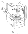
- FIG. 1 shows a dishwasher 10 as an example of one type of dishwasher with which the present invention may be used.
- the dishwasher includes a tub 12 (partly broken away in FIG. 1 to show internal details) forming an enclosure in which dishes, utensils, and dishware may be placed for washing.
- the tub includes a door 13 that may be opened to access the interior of the tub.
- the dishwasher includes a bottom rack and an upper rack (omitted from FIG. 1 for clarity, but shown in FIGS. 2 through 5 ) for holding the dishes, dishware, and utensils.
- Each of the racks is mounted to slide inwardly and outwardly through the open door to facilitate loading and unloading of dishes, dishware, and utensils.
- the tub also defines a sump (shown generally designated as 14 in FIG. 1 ) in which wash water or rinse water is collected.
- the water is pumped by a pump 15 from the sump 14 to various spray arms mounted in the interior of the tub for spraying the water under pressure onto the dishes, dishware, and utensils.
- the spray arms may be rotatable for ensuring that all areas in the interior of the tub are exposed to the water discharged from the spray arms.
- the upper rack may be adjustable to different vertical positions. This allows the user to lower the rack when inordinately tall items are to be placed in the upper rack, or to raise the rack when more vertical space is needed for items in the lower rack.
- the upper rack has three different positions that can be selected.
- the spray arms typically include an uppermost spray arm (not shown) mounted to an underside of an upper wall of the tub 12 for spraying water generally downwardly, and a lowermost spray arm 18 mounted on an upper side of a bottom wall of the tub for spraying water generally upwardly.
- the spray arms also include a mid-level spray arm 20 that is attached to an underside of the upper rack and is configured for spraying water both upwardly and downwardly.
- the spray arm 20 is supplied with water via a delivery tube 22 that extends generally horizontally along the underside of the upper rack. As will be appreciated by those of skill in the art, when the upper rack is adjusted to different vertical positions, the delivery tube 22 moves with the upper rack and thus also assumes different vertical positions.
- the water delivery system for the spray arm 20 may include a main supply conduit 24 that connects to the pump 15 at the lower end of the conduit, extends generally vertically upwardly adjacent a rear wall of the tub 12, and then turns to extend generally horizontally along the underside of the upper wall of the tub for supplying water to the uppermost spray arm.
- a check valve assembly 30 that cooperates with the delivery tube 22 to supply water to the mid-level spray arm 20.
- the check valve assembly 30 allows the delivery tube 22 to be fluidly coupled with the main supply conduit 24 when the upper rack is slid all the way into the interior of the tub 12, and to be disconnected from the main supply conduit when the upper rack is slid out for loading or unloading dishes and utensils.
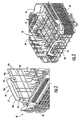
- the dishwasher may include a lower rack 40 ( FIGS. 2 and 3 ) located proximate the bottom wall of the tub and slidable into and out of the tub when the door is in the open position, and an upper rack 60 ( FIGS. 4 and 5 ) spaced vertically above the lower rack and slidable into and out of the tub when the door is in the open position (i.e., not blocking access to the interior of the tub).
- Each of the racks 40, 60 may be formed generally as a wire frame structure comprising, for example, a plurality of wires arranged to intersect one another at discrete points at which the wires are secured to one another.
- the lower rack 40 may have a bottom wall 42, a front wall 44 extending generally vertically upwardly from a front edge of the bottom wall, a rear wall 46 extending generally vertically upwardly from a rear edge of the bottom wall, and a pair of spaced side walls 48 extending generally vertically upwardly from opposite side edges of the bottom wall.
- the upper rack 60 may have a bottom wall 62, a front wall 64 extending generally vertically upwardly from a front edge of the bottom wall, a rear wall (not shown) extending generally vertically upwardly from a rear edge of the bottom wall, and a pair of spaced side walls 68 (only one visible in FIG. 5 ) extending generally vertically upwardly from opposite side edges of the bottom wall.
- the front wall 44, 64 of each rack may include at least two generally horizontal wires 44h, 64h, respectively, spaced apart in a vertical direction and a plurality of generally vertical wires 44v, 64v, respectively, spaced apart horizontally and secured to the at least two generally horizontal wires.
- the dishwasher may include a lower handle 50 secured to the front wall 44 of the lower rack 40, as shown in FIG. 2 and 3 .
- the lower handle 50 as in the illustrated embodiment, may have, for example, an inverted generally U-shaped configuration that includes a grasping portion 52 and a pair of legs 54 respectively projecting generally downward from the opposite ends of the grasping portion.
- the handle 50 may be formed to have two portions 50a and 50b each of which has the inverted generally U-shaped configuration.
- the two handle portions 50a, 50b may be secured to each other in a suitable fashion (e.g., by fasteners such as screws, by a snap-fit engagement, by adhesive, or the like) with a portion of the front wall 44 of the lower rack captured between the two handle portions 50a, 50b.
- the handle portion 50a faces toward the door of the dishwasher and the other handle portion 50b faces toward the rear wall of the tub.
- the two uppermost horizontal wires 44h of the front wall are captured between the two handle portions 50a, 50b in the region of the legs 54 of the handle.
- Each of the handle portions 50a, 50b may comprise a part molded from a polymer material in such a fashion that each handle portion has one side that is convex outwardly and an opposite side that is concave outwardly.
- the handle portions 50a, 50b may fit together with their concave sides facing each other, and thus the convex sides form the opposite surfaces of the handle 50 that will be grasped by the user.
- each handle portion 50a, 50b may define recesses for receiving the wires of the front wall 44.
- the handle portions 50a, 50b may be entirely separate from each other until they are secured together in any of the fashions previously noted; alternatively, the two handle portions may comprise a single one-piece member wherein, for example, a living hinge connects the handle portions to each other to allow them to be spread apart for engaging them around the front wall of the lower rack, after which the handle portions can be fit together and secured to each other as noted.
- the lower handle 50 may be configured and arranged with respect to the front wall 44 of the lower rack such that the grasping portion 52 of the handle is spaced above the upper edge of the front wall (which is defined by the uppermost horizontal wire 44h ) a sufficient distance so that a user's fingers can extend between the grasping portion 52 and the upper edge of the front wall. In this manner, the lower handle 50 is more easily accessible to the user and reduces the amount by which the user must bend down in order to grasp the grasping portion 52 to pull the lower rack 40 out from the dishwasher tub.
- the handle portions 50a, 50b may be molded from a thermoset polymer material.
- a thermoset polymer material Any of various thermoset polymer materials known in the art can be used, including but not limited to melamine resins, polyurethane resins, epoxy resins, unsaturated polyester resins, and the like.
- At least the outwardly facing (convex) surface of at least the front handle portion 50a may be plated with a powdered metal coating or any other suitable coating.
- the powdered metal coating may comprise, for example, a stainless steel powder, such as 304SS.
- the coating may provide a mirror finish.
- Stainless steel is highly resistant to rust and avoids the use of any heavy metals (e.g., chromium, nickel, or the like, which are typical materials for achieving bright mirror finishes) that potentially could leach out and contaminate the dishes and utensils being washed.
- the upper rack 60 similarly may have an upper handle 70 secured to the front wall 64 of the upper rack.
- the upper handle 70 as in the illustrated embodiment, may have an inverted generally U-shaped configuration that includes a grasping portion 72 and a pair of legs 54 respectively projecting generally downward from the opposite ends of the grasping portion.
- the handle 70 may be formed to have two portions 70a and 70b, each of which may have the inverted generally U-shaped configuration.
- the two handle portions 70a, 70b may be secured to each other in suitable fashion (e.g., using fasteners such as screws, by a snap-fit engagement, using adhesive, or the like) with a portion of the front wall 64 of the upper rack captured between the two handle portions.
- the handle portion 70a may face toward the door of the dishwasher and the other handle portion 70b faces toward the rear wall of the tub.
- the uppermost horizontal wire 64h of the front wall may be captured between the two handle portions 70a, 70b in the region of the grasping portion 72 of the handle, and the next-to-uppermost horizontal wire 64h is captured between the handle portions in the region of the legs 74.
- Each of the handle portions 70a, 70b may comprise a part molded from a polymer material in such a fashion that each handle portion has one side that is convex outwardly and an opposite side that is concave outwardly.
- the handle portions may fit together with their concave sides facing each other, and thus the convex sides form the opposite surfaces of the handle 70 that will be grasped by the user.
- the edges of each handle portion 70a, 70b may define recesses for receiving the wires of the front wall 64.
- the handle portions 70a, 70b may be entirely separate from each other until they are secured together in any of the fashions previously noted; alternatively, the two handle portions may comprise a single one-piece member wherein, for example, a living hinge connects the handle portions to each other to allow them to be spread apart for engaging them around the front wall of the lower rack, after which the handle portions can be fit together and secured to each other as noted.
- the upper handle 70 may be configured and arranged with respect to the front wall 64 of the upper rack such that the grasping portion 72 of the handle is at approximately the same level as the upper edge of the front wall (which is defined by the uppermost horizontal wire 64h ). There may be a sufficient distance between the grasping portion 72 and the next-to-uppermost horizontal wire 64h such that a user's fingers may extend between the grasping portion 72 and that wire.
- the handle portions 70a, 70b may be molded from a thermoset polymer material.
- a thermoset polymer material Any of various thermoset polymer materials known in the art can be used, including but not limited to melamine resins, polyurethane resins, epoxy resins, unsaturated polyester resins, and the like.
- At least the outwardly facing (convex) surface of at least the front handle portion 70a may be plated with a powdered metal coating or any other suitable coating.
- the powdered metal coating may comprise, for example, a stainless steel powder, such as 304SS.
- a further aspect of the invention relates to the proper functioning of the check valve assembly 30 ( FIG. 1 ) to connect the mid-level spray arm delivery tube 22 to the main supply conduit 24.
- the check valve assembly 30 FIG. 1
- the upper handle 70 may be configured and arranged to be contacted by the inner surface of the door 13 when the door is closed.
- the door may be configured to push on the upper handle 70 and urge the upper rack further inwardly to the correct position (but also avoids pushing the rack too far inwardly).
- handles 50, 70 described herein may be used in virtually all types of dishwashers that have racks that slide in and out, and are not limited to being used on dishwashers having the particular type of mid-level spray arm and water delivery system as described herein.
- both handle portions of a given handle may be plated with powdered stainless steel if desired.
- the handles may have shapes different from those illustrated and described herein, and/or the handles may be attached to the racks in ways different from those described herein. Therefore, it is to be understood that the inventions are not to be limited to the specific embodiments disclosed and that modifications and other embodiments are intended to be included within the scope of the appended claims. Although specific terms are employed herein, they are used in a generic and descriptive sense only and not for purposes of limitation.
Landscapes
- Washing And Drying Of Tableware (AREA)
- Main Body Construction Of Washing Machines And Laundry Dryers (AREA)
Priority Applications (1)
| Application Number | Priority Date | Filing Date | Title |
|---|---|---|---|
| PL08747311T PL2148606T3 (pl) | 2007-05-04 | 2008-05-01 | Człon uchwytowy półki do zmywarki |
Applications Claiming Priority (3)
| Application Number | Priority Date | Filing Date | Title |
|---|---|---|---|
| US91615607P | 2007-05-04 | 2007-05-04 | |
| US12/105,648 US8303725B2 (en) | 2007-05-04 | 2008-04-18 | Rack handle member for a dishwasher |
| PCT/US2008/062178 WO2008137518A2 (en) | 2007-05-04 | 2008-05-01 | Rack handle member for a dishwasher |
Publications (2)
| Publication Number | Publication Date |
|---|---|
| EP2148606A2 EP2148606A2 (en) | 2010-02-03 |
| EP2148606B1 true EP2148606B1 (en) | 2015-09-23 |
Family
ID=39938811
Family Applications (1)
| Application Number | Title | Priority Date | Filing Date |
|---|---|---|---|
| EP08747311.2A Not-in-force EP2148606B1 (en) | 2007-05-04 | 2008-05-01 | Rack handle member for a dishwasher |
Country Status (9)
| Country | Link |
|---|---|
| US (1) | US8303725B2 (pl) |
| EP (1) | EP2148606B1 (pl) |
| KR (2) | KR20100029747A (pl) |
| CN (1) | CN101686795B (pl) |
| AU (1) | AU2008247768B2 (pl) |
| CA (1) | CA2686327C (pl) |
| PL (1) | PL2148606T3 (pl) |
| RU (1) | RU2467676C2 (pl) |
| WO (1) | WO2008137518A2 (pl) |
Families Citing this family (13)
| Publication number | Priority date | Publication date | Assignee | Title |
|---|---|---|---|---|
| USD597395S1 (en) * | 2008-10-28 | 2009-08-04 | Steris Inc. | Cool touch handle |
| EP2364636B2 (en) | 2010-03-12 | 2020-08-12 | Electrolux Home Products Corporation N.V. | Cutlery tray, dishwasher basket and dishwasher |
| EP2377454B1 (de) | 2010-04-13 | 2019-12-25 | Miele & Cie. KG | Griff für einen Drahtkorb |
| KR101764294B1 (ko) * | 2011-01-19 | 2017-08-04 | 삼성전자주식회사 | 식기세척기 |
| KR101794060B1 (ko) | 2011-09-01 | 2017-11-06 | 삼성전자주식회사 | 식기 세척기 및 식기 세척기의 바스켓 고정 장치 |
| KR101293234B1 (ko) * | 2011-09-09 | 2013-08-05 | 엘지전자 주식회사 | 식기세척기 |
| PL2934275T3 (pl) | 2012-12-21 | 2021-06-14 | Electrolux Home Products Corporation N.V. | Moduł tacy na sztućce do zmywarki oraz zmywarka zawierająca co najmniej jeden moduł tacy na sztućce |
| EP2934277B1 (en) | 2012-12-21 | 2017-02-22 | Electrolux Home Products Corporation N.V. | Cutlery rack |
| AU354063S (en) | 2013-08-05 | 2014-03-03 | Electrolux Appliances AB | A dishwasher component |
| US9629516B2 (en) * | 2014-10-08 | 2017-04-25 | Whirlpool Corporation | Dishwasher rack handle |
| CN106943106A (zh) * | 2017-03-27 | 2017-07-14 | 佛山市顺德区美的洗涤电器制造有限公司 | 承载组件及洗碗机 |
| KR102627103B1 (ko) * | 2018-08-28 | 2024-01-22 | 엘지전자 주식회사 | 식기세척기용 랙, 식기세척기용 랙을 구비한 식기세척기 및 식기세척기용 랙의 제조방법 |
| US12121195B2 (en) | 2022-08-30 | 2024-10-22 | Haier Us Appliance Solutions, Inc. | Systems for rack operability in dishwashing appliances |
Family Cites Families (32)
| Publication number | Priority date | Publication date | Assignee | Title |
|---|---|---|---|---|
| US3039987A (en) | 1959-05-28 | 1962-06-19 | Westinghouse Electric Corp | Pulverulent coating compositions adapted for use in fluidizing processes containing epoxy resin and fillers |
| NL300096A (pl) * | 1962-11-13 | |||
| US3292984A (en) * | 1965-05-24 | 1966-12-20 | Gen Electric | Rack system for dishwashers |
| US3861769A (en) * | 1973-01-02 | 1975-01-21 | Gen Electric | Dishwasher rack |
| US4064887A (en) | 1976-07-27 | 1977-12-27 | Hobart Corporation | Upper level wash arm system |
| IT1159635B (it) | 1983-11-18 | 1987-03-04 | Indesit | Cestello per macchine lavastoviglie |
| SU1243656A1 (ru) | 1984-07-25 | 1986-07-15 | Mironov Vladimir A | Электронож дл вскрыти сотов |
| US4834125A (en) | 1987-03-23 | 1989-05-30 | Whirlpool Corporation | Removable utensil basket for a dishwasher |
| US5039477A (en) | 1989-06-02 | 1991-08-13 | Sugitani Kinzoku Kogyo Kabushiki Kaisha | Powdered metal spray coating material |
| DE59208375D1 (de) * | 1991-06-05 | 1997-05-28 | Ciba Geigy Ag | Benzo-1,2,3-thiadiazol-Derivate |
| US5284683A (en) | 1991-10-15 | 1994-02-08 | Semih Erhan | Method for metallization of plastics using poly-diamine-quinone polymers as a binder |
| IT243408Y1 (it) | 1997-01-23 | 2002-03-04 | Electrolux Zanussi Elettrodome | Cesto estraibile per lavastoviglie |
| DE19857317A1 (de) | 1998-12-11 | 2000-06-15 | Inst Neue Mat Gemein Gmbh | Haushaltsgeräte |
| IT1311224B1 (it) | 1999-06-01 | 2002-03-04 | Electrolux Zanussi Elettrodome | Macchina lavastoviglie,preferibilmente per uso domestico,avente una migliorata architettura |
| US6435366B1 (en) * | 1999-08-12 | 2002-08-20 | Maytag Corporation | Appliance washing tub having non-metallic reinforcing body and metallic inner liner |
| US6544596B2 (en) | 2000-11-29 | 2003-04-08 | Pacific Northwest Coatings | Method of coating a substrate using a thermosetting basecoat composition and a thermoplastic top coat composition |
| US20020139809A1 (en) * | 2000-12-27 | 2002-10-03 | Barry Rodney J. | Dishwasher silverware basket with swivel handle |
| US20020163285A1 (en) | 2001-05-04 | 2002-11-07 | Wayne Vanlandingham | Dishwasher rack with removable handle |
| DE20117421U1 (de) | 2001-10-24 | 2002-01-03 | Paul Hettich Gmbh & Co., 32278 Kirchlengern | Korbartiger Behälter eines Haushaltsgerätes |
| EP1454999A1 (de) | 2002-12-03 | 2004-09-08 | HARTEC GESELLSCHAFT FUR HARTSTOFFE UND DUNNSCHICHTTECHNIK MBH & CO. KG | Werkstoff oder Bauteil mit einer Metallbeschichtung |
| DE10259087B4 (de) | 2002-12-17 | 2004-11-25 | BSH Bosch und Siemens Hausgeräte GmbH | Geschirrkorb für eine Geschirrspülmaschine sowie Griff für einen Geschirrkorb |
| KR20040076668A (ko) | 2003-02-26 | 2004-09-03 | 삼성전자주식회사 | 식기 세척기 |
| KR100464520B1 (ko) | 2003-03-08 | 2005-01-03 | 삼성전자주식회사 | 식기세척기 |
| EP1564263A1 (fr) | 2004-01-30 | 2005-08-17 | Arkema | Poudre à base de polymère thermoplastique et son utilisation pour obtenir un revêtement rugueux |
| ATE335433T1 (de) | 2004-03-29 | 2006-09-15 | Electrolux Home Prod Corp | Geschirrspülmaschine mit warnanzeige vor zu heissem geschirr |
| KR20050105711A (ko) | 2004-05-03 | 2005-11-08 | 엘지전자 주식회사 | 식기 세척기의 랙구조 |
| DE202005004395U1 (de) | 2005-03-16 | 2005-05-25 | Electrolux Home Products Corporation N.V. | Beschichteter Geschirrkorb und Spülguthaltevorrichtung |
| KR20060100702A (ko) | 2005-03-17 | 2006-09-21 | 엘지전자 주식회사 | 수저류 수납 구조가 구비된 식기 세척기 |
| KR20060100705A (ko) | 2005-03-17 | 2006-09-21 | 엘지전자 주식회사 | 식기 세척기 |
| KR101178693B1 (ko) | 2005-03-17 | 2012-09-03 | 엘지전자 주식회사 | 식기 세척기 |
| KR100776434B1 (ko) | 2005-09-05 | 2007-11-16 | 엘지전자 주식회사 | 식기 세척기 |
| ATE420590T1 (de) | 2005-10-24 | 2009-01-15 | Electrolux Home Prod Corp | Geschirrkorb für geschirrspülmaschine |
-
2008
- 2008-04-18 US US12/105,648 patent/US8303725B2/en not_active Expired - Fee Related
- 2008-05-01 WO PCT/US2008/062178 patent/WO2008137518A2/en not_active Ceased
- 2008-05-01 CN CN2008800233184A patent/CN101686795B/zh not_active Expired - Fee Related
- 2008-05-01 KR KR1020097025317A patent/KR20100029747A/ko not_active Ceased
- 2008-05-01 RU RU2009140385/12A patent/RU2467676C2/ru not_active IP Right Cessation
- 2008-05-01 PL PL08747311T patent/PL2148606T3/pl unknown
- 2008-05-01 EP EP08747311.2A patent/EP2148606B1/en not_active Not-in-force
- 2008-05-01 AU AU2008247768A patent/AU2008247768B2/en not_active Ceased
- 2008-05-01 KR KR1020127013850A patent/KR20120079162A/ko not_active Ceased
- 2008-05-01 CA CA2686327A patent/CA2686327C/en not_active Expired - Fee Related
Also Published As
| Publication number | Publication date |
|---|---|
| RU2009140385A (ru) | 2011-06-10 |
| US20080272074A1 (en) | 2008-11-06 |
| PL2148606T3 (pl) | 2016-03-31 |
| US8303725B2 (en) | 2012-11-06 |
| CN101686795B (zh) | 2013-09-11 |
| CA2686327A1 (en) | 2008-11-13 |
| WO2008137518A2 (en) | 2008-11-13 |
| AU2008247768A1 (en) | 2008-11-13 |
| KR20120079162A (ko) | 2012-07-11 |
| KR20100029747A (ko) | 2010-03-17 |
| EP2148606A2 (en) | 2010-02-03 |
| CA2686327C (en) | 2014-09-09 |
| WO2008137518A3 (en) | 2009-02-12 |
| AU2008247768B2 (en) | 2011-06-09 |
| RU2467676C2 (ru) | 2012-11-27 |
| CN101686795A (zh) | 2010-03-31 |
Similar Documents
| Publication | Publication Date | Title |
|---|---|---|
| EP2148606B1 (en) | Rack handle member for a dishwasher | |
| US10722101B2 (en) | Dishwasher with slidable tine assembly | |
| US8900375B2 (en) | Two level conduit docking port mechanism for a dishwashing appliance | |
| EP1583455B1 (en) | Dishwasher | |
| CN110464282B (zh) | 洗碗机 | |
| US7665475B2 (en) | Utility shelf for a dishwasher dish rack | |
| US20180064309A1 (en) | Dish rack with dispenser unit | |
| EP3357399A1 (en) | Dish rack retaining clip | |
| US11638513B2 (en) | Dishwasher with moveable shelf | |
| WO2020117515A1 (en) | Commercial washer, which is in the form of an under-counter machine, and method for operating such a washer | |
| EP4048130B1 (en) | Dishwasher | |
| US20200146528A1 (en) | Dishwasher wash basket | |
| EP1790271A2 (en) | Flexible utility link for a drawer-type dishwasher | |
| US9408519B2 (en) | Dishwasher support structures to reduce rotation of a door crown | |
| US10376129B2 (en) | Dishwasher leveling assembly | |
| EP4197418A1 (en) | Dishwasher | |
| EP3199084A1 (en) | A basket system | |
| JP2025522095A (ja) | 食器を洗浄および保管するための家庭用機器 |
Legal Events
| Date | Code | Title | Description |
|---|---|---|---|
| PUAI | Public reference made under article 153(3) epc to a published international application that has entered the european phase |
Free format text: ORIGINAL CODE: 0009012 |
|
| 17P | Request for examination filed |
Effective date: 20091112 |
|
| AK | Designated contracting states |
Kind code of ref document: A2 Designated state(s): AT BE BG CH CY CZ DE DK EE ES FI FR GB GR HR HU IE IS IT LI LT LU LV MC MT NL NO PL PT RO SE SI SK TR |
|
| AX | Request for extension of the european patent |
Extension state: AL BA MK RS |
|
| 17Q | First examination report despatched |
Effective date: 20101125 |
|
| DAX | Request for extension of the european patent (deleted) | ||
| RAP1 | Party data changed (applicant data changed or rights of an application transferred) |
Owner name: ELECTROLUX HOME PRODUCTS, INC. |
|
| GRAP | Despatch of communication of intention to grant a patent |
Free format text: ORIGINAL CODE: EPIDOSNIGR1 |
|
| INTG | Intention to grant announced |
Effective date: 20150413 |
|
| GRAS | Grant fee paid |
Free format text: ORIGINAL CODE: EPIDOSNIGR3 |
|
| GRAA | (expected) grant |
Free format text: ORIGINAL CODE: 0009210 |
|
| AK | Designated contracting states |
Kind code of ref document: B1 Designated state(s): AT BE BG CH CY CZ DE DK EE ES FI FR GB GR HR HU IE IS IT LI LT LU LV MC MT NL NO PL PT RO SE SI SK TR |
|
| REG | Reference to a national code |
Ref country code: GB Ref legal event code: FG4D |
|
| REG | Reference to a national code |
Ref country code: CH Ref legal event code: EP |
|
| REG | Reference to a national code |
Ref country code: AT Ref legal event code: REF Ref document number: 750747 Country of ref document: AT Kind code of ref document: T Effective date: 20151015 |
|
| REG | Reference to a national code |
Ref country code: IE Ref legal event code: FG4D |
|
| REG | Reference to a national code |
Ref country code: DE Ref legal event code: R096 Ref document number: 602008040312 Country of ref document: DE |
|
| REG | Reference to a national code |
Ref country code: NL Ref legal event code: MP Effective date: 20150923 |
|
| PG25 | Lapsed in a contracting state [announced via postgrant information from national office to epo] |
Ref country code: LV Free format text: LAPSE BECAUSE OF FAILURE TO SUBMIT A TRANSLATION OF THE DESCRIPTION OR TO PAY THE FEE WITHIN THE PRESCRIBED TIME-LIMIT Effective date: 20150923 Ref country code: GR Free format text: LAPSE BECAUSE OF FAILURE TO SUBMIT A TRANSLATION OF THE DESCRIPTION OR TO PAY THE FEE WITHIN THE PRESCRIBED TIME-LIMIT Effective date: 20151224 Ref country code: LT Free format text: LAPSE BECAUSE OF FAILURE TO SUBMIT A TRANSLATION OF THE DESCRIPTION OR TO PAY THE FEE WITHIN THE PRESCRIBED TIME-LIMIT Effective date: 20150923 Ref country code: NO Free format text: LAPSE BECAUSE OF FAILURE TO SUBMIT A TRANSLATION OF THE DESCRIPTION OR TO PAY THE FEE WITHIN THE PRESCRIBED TIME-LIMIT Effective date: 20151223 Ref country code: FI Free format text: LAPSE BECAUSE OF FAILURE TO SUBMIT A TRANSLATION OF THE DESCRIPTION OR TO PAY THE FEE WITHIN THE PRESCRIBED TIME-LIMIT Effective date: 20150923 |
|
| REG | Reference to a national code |
Ref country code: LT Ref legal event code: MG4D |
|
| REG | Reference to a national code |
Ref country code: AT Ref legal event code: MK05 Ref document number: 750747 Country of ref document: AT Kind code of ref document: T Effective date: 20150923 |
|
| PG25 | Lapsed in a contracting state [announced via postgrant information from national office to epo] |
Ref country code: HR Free format text: LAPSE BECAUSE OF FAILURE TO SUBMIT A TRANSLATION OF THE DESCRIPTION OR TO PAY THE FEE WITHIN THE PRESCRIBED TIME-LIMIT Effective date: 20150923 Ref country code: SE Free format text: LAPSE BECAUSE OF FAILURE TO SUBMIT A TRANSLATION OF THE DESCRIPTION OR TO PAY THE FEE WITHIN THE PRESCRIBED TIME-LIMIT Effective date: 20150923 |
|
| PG25 | Lapsed in a contracting state [announced via postgrant information from national office to epo] |
Ref country code: NL Free format text: LAPSE BECAUSE OF FAILURE TO SUBMIT A TRANSLATION OF THE DESCRIPTION OR TO PAY THE FEE WITHIN THE PRESCRIBED TIME-LIMIT Effective date: 20150923 |
|
| PG25 | Lapsed in a contracting state [announced via postgrant information from national office to epo] |
Ref country code: IS Free format text: LAPSE BECAUSE OF FAILURE TO SUBMIT A TRANSLATION OF THE DESCRIPTION OR TO PAY THE FEE WITHIN THE PRESCRIBED TIME-LIMIT Effective date: 20160123 Ref country code: SK Free format text: LAPSE BECAUSE OF FAILURE TO SUBMIT A TRANSLATION OF THE DESCRIPTION OR TO PAY THE FEE WITHIN THE PRESCRIBED TIME-LIMIT Effective date: 20150923 Ref country code: ES Free format text: LAPSE BECAUSE OF FAILURE TO SUBMIT A TRANSLATION OF THE DESCRIPTION OR TO PAY THE FEE WITHIN THE PRESCRIBED TIME-LIMIT Effective date: 20150923 Ref country code: CZ Free format text: LAPSE BECAUSE OF FAILURE TO SUBMIT A TRANSLATION OF THE DESCRIPTION OR TO PAY THE FEE WITHIN THE PRESCRIBED TIME-LIMIT Effective date: 20150923 Ref country code: EE Free format text: LAPSE BECAUSE OF FAILURE TO SUBMIT A TRANSLATION OF THE DESCRIPTION OR TO PAY THE FEE WITHIN THE PRESCRIBED TIME-LIMIT Effective date: 20150923 |
|
| REG | Reference to a national code |
Ref country code: FR Ref legal event code: PLFP Year of fee payment: 9 |
|
| PG25 | Lapsed in a contracting state [announced via postgrant information from national office to epo] |
Ref country code: PT Free format text: LAPSE BECAUSE OF FAILURE TO SUBMIT A TRANSLATION OF THE DESCRIPTION OR TO PAY THE FEE WITHIN THE PRESCRIBED TIME-LIMIT Effective date: 20160125 Ref country code: AT Free format text: LAPSE BECAUSE OF FAILURE TO SUBMIT A TRANSLATION OF THE DESCRIPTION OR TO PAY THE FEE WITHIN THE PRESCRIBED TIME-LIMIT Effective date: 20150923 Ref country code: RO Free format text: LAPSE BECAUSE OF FAILURE TO SUBMIT A TRANSLATION OF THE DESCRIPTION OR TO PAY THE FEE WITHIN THE PRESCRIBED TIME-LIMIT Effective date: 20150923 |
|
| REG | Reference to a national code |
Ref country code: DE Ref legal event code: R097 Ref document number: 602008040312 Country of ref document: DE |
|
| PLBE | No opposition filed within time limit |
Free format text: ORIGINAL CODE: 0009261 |
|
| STAA | Information on the status of an ep patent application or granted ep patent |
Free format text: STATUS: NO OPPOSITION FILED WITHIN TIME LIMIT |
|
| 26N | No opposition filed |
Effective date: 20160624 |
|
| PG25 | Lapsed in a contracting state [announced via postgrant information from national office to epo] |
Ref country code: DK Free format text: LAPSE BECAUSE OF FAILURE TO SUBMIT A TRANSLATION OF THE DESCRIPTION OR TO PAY THE FEE WITHIN THE PRESCRIBED TIME-LIMIT Effective date: 20150923 Ref country code: BE Free format text: LAPSE BECAUSE OF NON-PAYMENT OF DUE FEES Effective date: 20160531 |
|
| PG25 | Lapsed in a contracting state [announced via postgrant information from national office to epo] |
Ref country code: SI Free format text: LAPSE BECAUSE OF FAILURE TO SUBMIT A TRANSLATION OF THE DESCRIPTION OR TO PAY THE FEE WITHIN THE PRESCRIBED TIME-LIMIT Effective date: 20150923 |
|
| PG25 | Lapsed in a contracting state [announced via postgrant information from national office to epo] |
Ref country code: LU Free format text: LAPSE BECAUSE OF FAILURE TO SUBMIT A TRANSLATION OF THE DESCRIPTION OR TO PAY THE FEE WITHIN THE PRESCRIBED TIME-LIMIT Effective date: 20160501 Ref country code: BE Free format text: LAPSE BECAUSE OF FAILURE TO SUBMIT A TRANSLATION OF THE DESCRIPTION OR TO PAY THE FEE WITHIN THE PRESCRIBED TIME-LIMIT Effective date: 20150923 |
|
| REG | Reference to a national code |
Ref country code: IE Ref legal event code: MM4A |
|
| REG | Reference to a national code |
Ref country code: FR Ref legal event code: PLFP Year of fee payment: 10 |
|
| PG25 | Lapsed in a contracting state [announced via postgrant information from national office to epo] |
Ref country code: IE Free format text: LAPSE BECAUSE OF NON-PAYMENT OF DUE FEES Effective date: 20160501 |
|
| PGFP | Annual fee paid to national office [announced via postgrant information from national office to epo] |
Ref country code: FR Payment date: 20170523 Year of fee payment: 10 Ref country code: DE Payment date: 20170523 Year of fee payment: 10 Ref country code: CH Payment date: 20170519 Year of fee payment: 10 Ref country code: GB Payment date: 20170519 Year of fee payment: 10 |
|
| PGFP | Annual fee paid to national office [announced via postgrant information from national office to epo] |
Ref country code: PL Payment date: 20170421 Year of fee payment: 10 Ref country code: IT Payment date: 20170526 Year of fee payment: 10 |
|
| PGFP | Annual fee paid to national office [announced via postgrant information from national office to epo] |
Ref country code: TR Payment date: 20170420 Year of fee payment: 10 |
|
| PG25 | Lapsed in a contracting state [announced via postgrant information from national office to epo] |
Ref country code: CY Free format text: LAPSE BECAUSE OF FAILURE TO SUBMIT A TRANSLATION OF THE DESCRIPTION OR TO PAY THE FEE WITHIN THE PRESCRIBED TIME-LIMIT Effective date: 20150923 Ref country code: HU Free format text: LAPSE BECAUSE OF FAILURE TO SUBMIT A TRANSLATION OF THE DESCRIPTION OR TO PAY THE FEE WITHIN THE PRESCRIBED TIME-LIMIT; INVALID AB INITIO Effective date: 20080501 |
|
| PG25 | Lapsed in a contracting state [announced via postgrant information from national office to epo] |
Ref country code: MT Free format text: LAPSE BECAUSE OF NON-PAYMENT OF DUE FEES Effective date: 20160531 Ref country code: MC Free format text: LAPSE BECAUSE OF FAILURE TO SUBMIT A TRANSLATION OF THE DESCRIPTION OR TO PAY THE FEE WITHIN THE PRESCRIBED TIME-LIMIT Effective date: 20150923 |
|
| PG25 | Lapsed in a contracting state [announced via postgrant information from national office to epo] |
Ref country code: BG Free format text: LAPSE BECAUSE OF FAILURE TO SUBMIT A TRANSLATION OF THE DESCRIPTION OR TO PAY THE FEE WITHIN THE PRESCRIBED TIME-LIMIT Effective date: 20150923 |
|
| REG | Reference to a national code |
Ref country code: DE Ref legal event code: R119 Ref document number: 602008040312 Country of ref document: DE |
|
| REG | Reference to a national code |
Ref country code: CH Ref legal event code: PL |
|
| GBPC | Gb: european patent ceased through non-payment of renewal fee |
Effective date: 20180501 |
|
| PG25 | Lapsed in a contracting state [announced via postgrant information from national office to epo] |
Ref country code: CH Free format text: LAPSE BECAUSE OF NON-PAYMENT OF DUE FEES Effective date: 20180531 Ref country code: LI Free format text: LAPSE BECAUSE OF NON-PAYMENT OF DUE FEES Effective date: 20180531 |
|
| PG25 | Lapsed in a contracting state [announced via postgrant information from national office to epo] |
Ref country code: FR Free format text: LAPSE BECAUSE OF NON-PAYMENT OF DUE FEES Effective date: 20180531 Ref country code: DE Free format text: LAPSE BECAUSE OF NON-PAYMENT OF DUE FEES Effective date: 20181201 Ref country code: GB Free format text: LAPSE BECAUSE OF NON-PAYMENT OF DUE FEES Effective date: 20180501 Ref country code: IT Free format text: LAPSE BECAUSE OF NON-PAYMENT OF DUE FEES Effective date: 20180501 |
|
| PG25 | Lapsed in a contracting state [announced via postgrant information from national office to epo] |
Ref country code: PL Free format text: LAPSE BECAUSE OF NON-PAYMENT OF DUE FEES Effective date: 20180501 |
|
| PG25 | Lapsed in a contracting state [announced via postgrant information from national office to epo] |
Ref country code: TR Free format text: LAPSE BECAUSE OF NON-PAYMENT OF DUE FEES Effective date: 20180501 |