EP2148513A2 - Video coding - Google Patents
Video coding Download PDFInfo
- Publication number
- EP2148513A2 EP2148513A2 EP09013205A EP09013205A EP2148513A2 EP 2148513 A2 EP2148513 A2 EP 2148513A2 EP 09013205 A EP09013205 A EP 09013205A EP 09013205 A EP09013205 A EP 09013205A EP 2148513 A2 EP2148513 A2 EP 2148513A2
- Authority
- EP
- European Patent Office
- Prior art keywords
- picture
- reference picture
- area
- video signal
- pictures
- Prior art date
- Legal status (The legal status is an assumption and is not a legal conclusion. Google has not performed a legal analysis and makes no representation as to the accuracy of the status listed.)
- Granted
Links
Images


Classifications
-
- H—ELECTRICITY
- H04—ELECTRIC COMMUNICATION TECHNIQUE
- H04N—PICTORIAL COMMUNICATION, e.g. TELEVISION
- H04N19/00—Methods or arrangements for coding, decoding, compressing or decompressing digital video signals
- H04N19/10—Methods or arrangements for coding, decoding, compressing or decompressing digital video signals using adaptive coding
- H04N19/102—Methods or arrangements for coding, decoding, compressing or decompressing digital video signals using adaptive coding characterised by the element, parameter or selection affected or controlled by the adaptive coding
- H04N19/103—Selection of coding mode or of prediction mode
- H04N19/105—Selection of the reference unit for prediction within a chosen coding or prediction mode, e.g. adaptive choice of position and number of pixels used for prediction
-
- H—ELECTRICITY
- H04—ELECTRIC COMMUNICATION TECHNIQUE
- H04N—PICTORIAL COMMUNICATION, e.g. TELEVISION
- H04N19/00—Methods or arrangements for coding, decoding, compressing or decompressing digital video signals
- H04N19/50—Methods or arrangements for coding, decoding, compressing or decompressing digital video signals using predictive coding
- H04N19/503—Methods or arrangements for coding, decoding, compressing or decompressing digital video signals using predictive coding involving temporal prediction
- H04N19/51—Motion estimation or motion compensation
- H04N19/577—Motion compensation with bidirectional frame interpolation, i.e. using B-pictures
-
- H—ELECTRICITY
- H04—ELECTRIC COMMUNICATION TECHNIQUE
- H04N—PICTORIAL COMMUNICATION, e.g. TELEVISION
- H04N19/00—Methods or arrangements for coding, decoding, compressing or decompressing digital video signals
- H04N19/50—Methods or arrangements for coding, decoding, compressing or decompressing digital video signals using predictive coding
- H04N19/503—Methods or arrangements for coding, decoding, compressing or decompressing digital video signals using predictive coding involving temporal prediction
- H04N19/51—Motion estimation or motion compensation
-
- H—ELECTRICITY
- H04—ELECTRIC COMMUNICATION TECHNIQUE
- H04N—PICTORIAL COMMUNICATION, e.g. TELEVISION
- H04N19/00—Methods or arrangements for coding, decoding, compressing or decompressing digital video signals
- H04N19/65—Methods or arrangements for coding, decoding, compressing or decompressing digital video signals using error resilience
-
- H—ELECTRICITY
- H04—ELECTRIC COMMUNICATION TECHNIQUE
- H04N—PICTORIAL COMMUNICATION, e.g. TELEVISION
- H04N19/00—Methods or arrangements for coding, decoding, compressing or decompressing digital video signals
- H04N19/85—Methods or arrangements for coding, decoding, compressing or decompressing digital video signals using pre-processing or post-processing specially adapted for video compression
- H04N19/89—Methods or arrangements for coding, decoding, compressing or decompressing digital video signals using pre-processing or post-processing specially adapted for video compression involving methods or arrangements for detection of transmission errors at the decoder
- H04N19/895—Methods or arrangements for coding, decoding, compressing or decompressing digital video signals using pre-processing or post-processing specially adapted for video compression involving methods or arrangements for detection of transmission errors at the decoder in combination with error concealment
Definitions
- This invention relates to video coding.
- a video sequence consists of a series of still pictures or frames.
- Video compression methods are based on reducing the redundant and perceptually irrelevant parts of video sequences.
- the redundancy in video sequences can be categorised into spectral, spatial and temporal redundancy.
- Spectral redundancy refers to the similarity between the different colour components of the same picture. Spatial redundancy results from the similarity between neighbouring pixels in a picture.
- Temporal redundancy exists because objects appearing in a previous image are also likely to appear in the current image. Compression can be achieved by taking advantage of this temporal redundancy and predicting the current picture from another picture, termed an anchor or reference picture. Further compression is achieved by generating motion compensation data that describes the motion between the current picture and the previous picture.
- Video compression methods typically differentiate between pictures that utilise temporal redundancy reduction and those that do not.
- Compressed pictures that do not utilise temporal redundancy reduction methods are usually called INTRA or I-frames or I-pictures.
- Temporally predicted images are usually forwardly predicted from a picture occurring before the current picture and are called INTER or P-frames. In the INTER frame case, the predicted motion-compensated picture is rarely precise enough and therefore a spatially compressed prediction error frame is associated with each INTER frame.
- INTER pictures may contain INTRA-coded areas.
- B-pictures are inserted between anchor picture pairs of I- and/or P-frames and are predicted from either one or both of these anchor pictures.
- B-pictures normally yield increased compression as compared with forward-predicted pictures.
- B-pictures are not used as anchor pictures, i.e., other pictures are not predicted from them. Therefore they can be discarded (Intentionally or unintentionally) without impacting the picture quality of future pictures.
- B-pictures may improve compression performance as compared with P-pictures, their generation requires greater computational complexity and memory usage, and they introduce additional delays. This may not be a problem for non-real time applications such as video streaming but may cause problems in real-time applications such as video-conferencing,
- a compressed video clip typically consists of a sequence of pictures, which can be roughly categorised into temporally Independent INTRA pictures and temporally differentially coded INTER pictures. Since the compression efficiency in INTRA pictures is normally lower than in INTER pictures, INTRA pictures are used sparingly, especially In low bit-rate applications.
- a video sequence may consist of a number of scenes or shots.
- the picture contents may be remarkably different from one scene to another, and therefore the first picture of a scene is typically INTRA-coded.
- INTRA pictures are typically inserted to stop temporal propagation of transmission errors in a reconstructed video signal and to provide random access points to a video bit-stream.
- Compressed video is easily corrupted by transmission errors, mainly for two reasons. Firstly, due to utilisation of temporal predictive differential coding (INTER frames), an error is propagated both spatially and temporally. In practice this means that, once an error occurs, it is easily visible to the human eye for a relatively long time. Especially susceptible are transmissions at low bit-rates where there are only a few INTRA-coded frames, so temporal error propagation is not stopped for some time. Secondly, the use of variable length codes increases the susceptibility to errors. When a bit error alters the codeword, the decoder will lose codeword synchronisation and also decode subsequent error-free codewords (comprising several bits) incorrectly until the next synchronisation (or start) code.
- INTER frames temporal predictive differential coding
- a synchronisation code is a bit pattern which cannot be generated from any legal combination of other codewords and such codes are added to the bit stream at intervals to enable re-synchronisation.
- errors occur when data is lost during transmission.
- network elements may discard parts of the encoded video bit-stream.
- Error correction refers to the process of recovering the erroneous data perfectly as if no errors had been introduced in the first place.
- Error concealment refers to the process of concealing the effects of transmission errors so that they are hardly visible in the reconstructed video sequence. Typically some amount of redundancy is added by the source or transport coding in order to help error detection, correction and concealment.
- the hierarchy has four layers: picture, picture segment, macroblock, and block layer.
- the picture layer data contain parameters affecting the whole picture area and the decoding of the picture data. Most of this data is arranged in a so-called picture header.
- the picture segment layer can either be a group of blocks layer or a slice layer.
- each picture is divided into groups of blocks.
- a group of blocks (GOB) typically comprises 16 successive pixel lines.
- Data for each GOB consists of an optional GOB header followed by data for macroblocks. If the optional slice structured mode is used, each picture is divided into slices instead of GOBs, A slice contains a number of successive macroblocks in scan-order. Data for each slice consists of a slice header followed by data for the macroblocks.
- a macroblock relates to 16 x 16 pixels (or 2 x 2 blocks) of luminance and the spatially corresponding 8 x 8 pixels (or block) of chrominance components.
- a block relates to 8 x 8 pixels of luminance or chrominance.
- Block layer data consist of uniformly quantised discrete cosine transform coefficients, which are scanned in zigzag order, processed with a run-length encoder and coded with variable length codes.
- MPEG-2 and MPEG-4 layer hierarchies resemble the one in H.263.
- these standards use the temporally previous anchor (I, EI, P, or EP) picture as a reference for temporal prediction.
- This piece of information is not transmitted, i.e. the bit-stream does not contain information relating to the identity of the reference picture. Consequently, decoders have no means to detect if a reference picture is lost.
- Many transport coders packetise video data in such a way that they associate a sequence number with the packets. However, these kinds of sequence numbers are not related to the video bit-stream. For example, a section of a video bit-stream may contain the data for P-picture P1, B-picture B2, P-picture P3, and P-picture P4 captured (and to be displayed) in this order.
- this section of the video bitstream would be compressed, transmitted, and decoded in the following order: P1, P3, B2, P4 since B2 requires both P1 and P3 before it can be encoded or decoded.
- P1, P3, B2, P4 since B2 requires both P1 and P3 before it can be encoded or decoded.
- the decoder therefore usually sends an INTRA request to the transmitter and freezes the picture on the display.
- the transmitter may not be able to respond to this request.
- the transmitter cannot respond to an INTRA request from a decoder. Therefore the decoder freezes the picture until the next INTRA frame is received.
- the transmitter may not be able to respond.
- the encoder may not be able to respond to individual requests. Again the decoder freezes the picture until an INTRA frame is output by the transmitter.
- a method of encoding a video signal representing a sequence of pictures comprising receiving a current picture for encoding, forming a temporal prediction of the current picture from a default reference picture for the current picture, comparing the default reference picture with at least one further reference picture, calculating a measure of the similarity between the default reference picture and each further reference picture and, if the measure of similarity meets a pre-determined criterion, outputting an indicator identifying the further reference picture and associating the indicator with the temporal prediction of the current frame.
- Encoders can use this indicator to instruct decoders which pictures resemble the current motion compensation reference picture so well that one of them can be used as a spare reference picture if the actual reference picture is lost during transmission. If a decoder lacks an actual reference picture but can access a spare reference picture, preferably the decoder should not send a request for an INTRA picture update.
- the indicator may be termed a spare reference picture number since the indicator indicates to a decoder which reference picture(s) resemble the default reference picture. This "spare" reference picture may be used by a decoder to decode the current frame if the default reference picture is lost for some reason.
- the spare reference picture number may be in respect of the whole picture or part of a picture. In the former case, typically the spare reference picture number is included in a picture header. In the latter case the spare reference picture number is included in the picture segment headers or macroblock headers of the picture.
- the video signal is encoded according to the H.263 standard and the indicator is included in the Supplemental Enhancement Information.
- the method also comprises forming a temporal prediction of the current picture from a first default reference picture and a second default reference picture for the current picture, said first default reference picture occurring temporally before the current picture and said second default reference picture occurring temporally after the current picture, comparing the first default reference picture with at least one further reference picture occurring temporally before the current picture, calculating a measure of the similarity between the first default reference picture and each further reference picture and, if the measure of similarity meets a pre-determined criterion, outputting an indicator identifying the further reference picture.
- an indicator is provided for forwardly predicted frames but not for backwardly predicted frames.
- the default reference picture is compared with a plurality of further reference pictures and an indicator is output for each further reference picture that meets the predetermined criterion.
- the further reference pictures that meet the predetermined criterion are linked in order of similarity and the indicator is associated with the temporal prediction of the current frame in order of rank, the further reference picture having the closest similarity to the default reference picture being placed first.
- the comparison may be carried out for portions of a picture at a time e.g. blocks or other non-rectangular areas of the pictures.
- a method of encoding a video signal representing a sequence of pictures comprising receiving a current picture for encoding, forming a prediction of at least part of the current picture from a default reference picture for the current picture, comparing the part of the default reference picture or the current picture with a corresponding part of at least one further picture of the sequence to form a measure of similarity and, if the measure of similarity meets a pre-determined criterion, outputting an indicator in respect of the part of the current frame Identifying the further picture of the sequence.
- a method of decoding an encoded video signal representing a sequence of pictures comprising receiving an encoded video signal representing a current picture and decoding at least the picture header of the current picture wherein, when the decoder Is unable to decode the default reference picture of the current picture, examining an indicator Identifying a further reference picture and decoding the current picture with reference to said further reference picture if such an indicator is associated with the current picture.
- a video encoder comprising an input for receiving a video signal representing a sequence of pictures, an input for receiving a current picture for encoding, a predictive coder for forming a temporal prediction of the current picture from a default reference picture for the current picture, a comparator for comparing the default reference picture or the current picture with at least one further reference picture and calculating a measure of the similarity and, when the measure of similarity meets a pre-determlned criterion, outputting an indicator identifying the further reference picture.
- a video decoder comprising an input for receiving an encoded video signal representing a sequence of pictures, the encoded signal including pictures that have been encoded by forming a temporal prediction of a current picture from a default reference picture for the current picture, the decoder comprising an Input for receiving an encoded video signal representing a current picture and a processor for decoding at least the picture header of the current picture wherein, when the decoder is unable to decode the default reference picture of the current picture, the decoder is arranged to examine an indicator identifying a further reference picture and to decode the current picture with reference to said further reference picture if such an indicator is associated with the current picture.
- the invention also relates to a radio telecommunications device including an encoder and/or a decoder as described.
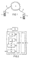
- Figure 1 shows a typical multimedia mobile communications system.
- a first multimedia mobile terminal1 1 communicates with a second multimedia mobile terminal 2 via a radio link 3 to a mobile communications network 4.
- Control data is sent between the two terminals 1,2 as well as the multimedia data.
- FIG. 2 shows the typical multimedia components of a terminal 1.
- the terminal comprises a video codec 10, an audio codec 20, a data protocol manager 30, a control manager 40, a multiplexer/demultiplexer 50 and a modem 60 (if the required).
- the video codec 10 receives signals for coding from a video capture device of the terminal (not shown) (e.g. a camera) and receives signals for decoding from a remote terminal 2 for display by the terminal 1 on a display 70.
- the audio codec 20 receives signals for coding from the microphone (not shown) of the terminal 1 and receives signals for decoding from a remote terminal 2 for reproduction by a loudspeaker (not shown) of the terminal 1.
- the terminal may be a portable radio communications device, such as a radio telephone.
- the control manager 40 controls the operation of the video codec 10, the audio codec 20 and the data protocols manager 30. However, since the invention is concerned with the operation of the video codec 10, no further discussion of the audio codec 20 and data protocols manager 30 will be provided.
- Figure 3 shows an example of a video codec 10 according to the invention.
- the video codec comprises an encoder part 100 and a decoder part 200.
- the encoder part 100 comprises an input 101 for receiving a video signal from a camera or video source (not shown) of the terminal 1.
- a switch 102 switches the encoder between an INTRA-mode of coding and an INTER-mode.
- the encoder part 100 of the video codec 10 comprises a DCT transformer 103, a quantiser 104, an inverse quantiser 108, an inverse DCT transformer 109, an adder 110, a plurality of picture stores 107 (see Figure 3a for more detail), a subtractor 106 for forming a prediction error, a switch 113 and an encoding control manager 105.
- the decoder part 200 of the video codec 10 comprises an inverse quantiser 120, an inverse DCT transformer 121, a motion compensator 122, a plurality of picture stores 123 and a controller 124.
- the controller 124 receives video codec control signals demultiplexed from the encoded multimedia stream by the demultiplexer 50.
- the controller 105 of the encoder and the controller 124 of the decoder may be the same processor.
- the video codec 10 receives a video signal to be encoded.
- the encoder 100 of the video codec encodes the video signal by performing DCT transformation, quantisation and motion compensation.
- the encoded video data is then output to the multiplexer 50.
- the multiplexer 50 multiplexes the video data from the video codec 10 and control data from the control 40 (as well as other signals as appropriate) into a multimedia signal.
- the terminal 1 outputs this multimedia signal to the receiving teminal 2 via the modem 60 (if required).
- the video signal from the input 101 is transformed to DCT co-efficients by a DCT transformer 103.
- the DCT coefficients are then passed to the quantiser 104 that quantises the coefficients.
- Both the switch 102 and the quantiser 104 are controlled by the encoding control manager 105 of the video codec, which may also receive feedback control from the receiving terminal 2 by means of the control manager 40.
- a decoded picture is then formed by passing the data output by the quantiser through the inverse quantiser 108 and applying an inverse DCT transform 109 to the inverse-quantised data.
- the resulting data is then input to the adder 110.
- the switch 113 is set so that the input to the adder 110 from the switch 113 is set to zero. The two inputs to the adder 110 are added together and the resulting data input to the picture store 107.
- the switch 102 is operated to accept from the subtractor 106 the difference between the signal from the input 101 and a reference picture which is stored in a picture store 107.
- the difference data output from the subtractor 106 represents the prediction error between the current picture and the reference picture stored in the picture store 107.
- a motion estimator 111 may generate motion compensation data with reference to the data in the picture store 107 in a conventional manner.
- the encoding control manager 105 decides whether to apply INTRA or INTER coding or whether to code the frame at all on the basis of either the output of the subtractor 106 or in response to feedback control data from a receiving decoder.
- the encoding control manager may decide not to code a received frame at all when the similarity between the current frame and the reference frame is so high or there is not time to code the frame.
- the encoding control manager operates the switch 102 accordingly,
- the encoder When not responding to feedback control data, the encoder typically encodes a frame as an INTRA-frame either only at the start of coding (all other frames being P-frames), or at regular periods e.g. every 5s, or when the output of the subtractor exceeds a threshold i.e. when the current picture and that stored in the picture store 107 are judged to be too dissimilar.
- the encoder may also be programmed to encode frames in a particular regular sequence e.g. I B B P B B P B B P B B P B B P B B B I B B P etc.
- the video codec outputs the quantised DCT coefficients 112a, the quantising index 112b (i.e. the details of the quantising used), an INTRA/INTER flag 112c to indicate the mode of coding performed (I or P/B), a transmit flag 112d to indicate the number of the frame being coded and (in INTER mode) the motion vectors 112e for the picture being coded. These are multiplexed together with other multimedia signals by the multiplexer 50.
- the encoder 100 will be described further with reference to Figure 3a , which shows a simplified view of the encoder 100 of the video codec.
- the encoder 100 comprises a plurality of picture stores 107a-107g. Although in this example seven picture stores are shown, the number of picture stores may be two or more.
- the frames are received from a video capture device in the order 0,1,2,3,4,5,6 etc. and are displayed in this order i.e. the decoded frames are displayed in the order 10,B1,B2,P3,B4,B5,P6 etc.
- the video bit stream is compressed, transmitted and decoded in the following order 10, P3, B1, B2, P6, 84, B5 etc. This is because each B-frame requires preceding and succeeding reference frames before it can be encoded/decoded i.e. frame B1 requires frame I0 and P3 to be encoded/decoded before it can be encoded/decoded.
- the next picture to be coded is frame 3, which is to be forwardly predicted from 10. Therefore when frame 3 is input at 101, switch 102 Is changed to the INTER mode, the output switch 115 of the most recent reference picture store (i.e. switch 115a) is closed and the motion compensated contents of picture store 107a are subtracted from the input signal, motion compensation data having been calculated in the conventional manner, This prediction error is then encoded by DCT 103 and quantiser 104 and decoded by inverse quantiser 108 and IDCT 109.
- adder 110 adds the decoded picture to the picture as stored in picture store 107a and stores the result in picture store 107b.
- the next frame to be coded is frame 2, which is to be coded as a B-frame.
- frame 2 which is to be coded as a B-frame.
- the contents of both of the frame stores 107a and 107b are made available to the subtractor 106 in a conventional manner, Since B-frames do not form a reference picture for any other frame, the encoded B-frame is not decoded and stored in a reference picture store.
- the frame stores 107a to 107g contain decoded versions of frames 10, P3, P6, P9, P12, P15 and P18 respectively.
- the encoding control manager 105 may associate with the frame a Spare Reference Picture Number (SRPN).
- SRPN Spare Reference Picture Number
- a SRPN may be associated with the P and B frames of a video signal but not with the I-frames.
- Encoders can use this message to instruct decoders which reference picture or pictures resemble the current reference picture, so that one of them can be used as a spare reference picture if the actual reference picture is lost during transmission.
- the encoder calculates the similarity between the default reference picture of the current frame (i.e. frame 3 for frame 6) and the contents of the other populated picture stores i.e. picture store 107a. If two reference pictures are sufficiently similar (e.g. the correlation between the contents of frame store 107a and 107b is above a threshold), the encoder associates a SRPN with the data for frame 6. The SRPN identifies frame 0 as a spare reference picture. However, if the similarity is not sufficient, no SRPN is associated with frame 6.
- a Sum of Absolute Differences may be used as a measure of similarity.
- an SAD value is calculated by taking the difference in value between spatially corresponding pixels in the default reference picture for the current frame and another "potential" reference frame i.e. a frame stored in one of the picture stores 107. The absolute value of each difference is obtained and the absolute difference values are accumulated to form the SAD. In this way, the SAD is representative of the similarity between the default reference frame and the other potential reference frame.
- two pictures can be deemed sufficiently similar when the SAD between them is below a threshold.
- the similarity of the default reference frame and another potential reference frame for the current picture can be assessed using picture histograms.
- a picture histogram is a measure of the number of occurrences of pixel values within a given image and two pictures can be deemed similar if their histograms correspond to a significant degree.
- the encoder instead of determining the similarity between the default reference frame for the current frame and another potential reference frame, the encoder examines the similarity between another potential reference frame available in one of the picture stores 107 and the current frame itself.
- a threshold is set defining the maximum difference allowable between the current frame and the potential reference frame.
- SAD Sum of Absolute Differences
- image histogram or any other appropriate method can be used to assess the degree of similarity / difference between the current frame and the other potential reference frame(s).
- frame 15 when frame 15 is to be encoded (as a P-frame), decoded versions of frames 0, 3, 6, 9 and 12 are held in picture stores 114a-e respectively.
- frame 15 is encoded with reference to frame 12 as stored in picture store 107e.
- the encoder also carries out a calculation of the correlation between the data in the picture store 107e and the data stored in the other populated picture stores 107a-d.
- the encoder identifies the picture store (and hence the reference picture) that has the closest correlation with the contents of picture store 107e i.e. with the default reference picture for the current frame being coded.
- the encoder than adds a SRPN to the encoded data that indicates the identified reference picture.
- This SRPN can be equal to the Temporal Reference of the reference picture as will be described below.
- More than one SRPN may be associated with a frame.
- the SRPN are ordered within the picture header in the order of similarity, the most similar reference picture (other than the default) being mentioned first.
- the encoding control manager 105 outputs this SRPN codeword on output 112f which indicates the Spare Reference Picture Number associated with the encoded frame. This is multiplexed into the video bitstream by a multiplexer.
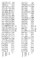
- Figure 4 illustrates the operation of a first embodiment of the encoder.
- the first line of Figure 4 represents the frames of data received from a capture input device and input to the video coder on input 101.
- the second line of Figure 4 represents those frames of the input signal that the encoder decides to encode and the coding mode used to encode each frame.
- the encoder is arranged to encode every frame and to use the IBBP coding format.
- Frame 0 is coded in INTRA-mode; frame 1 is encoded as a B-frame with reference to frame 0 and/or 3; frame 2 is encoded as a B-frame with reference to frame 0 and/or 3; frame 3 is encoded as a P-frame with reference to frame 0; frame 4 is encoded as a B-frame with reference to frame 3 and/or 6; frame 5 is encoded as a B-frame with reference to frame 3 and/or 6; frame 6 is encoded as a P-frame with reference to frame 3; etc.
- the third line of Figure 4 shows a SRPN field associated with frames of the encoded signal.
- a SRPN is associated with the P-frames and B-frames, as shown in the third line of Figure 4 .
- the P-frames and B-frames of the encoded frames are temporally predictively encoded and the I-frames are not.
- the fourth line of Figure 4 shows the Temporal Reference (TR) of the encoded frame.
- TR Temporal Reference
- This is a field included in H.263 and the value of TR is formed by incrementing its value in the temporally previous reference picture header by one plus the number of skipped or non-reference pictures since the previously transmitted reference picture.
- the TR shown for each frame is the same as the original temporal order of the frames in the original signal input to 101.
- Figure 5 illustrates the operation of a second embodiment of an encoder according to the invention.
- the encoder is arranged to code the frames according to the regular sequence I B B P B B P B B P B B B I B B P B B P.
- a SRPN is associated with forwardly predicted frames (i.e. P-frames) only.
- the first line of Figure 5 shows the input frames and the second line shows the coded frames and their coding mode, I, P or B.
- the third line of Figure 5 shows the SRPN associated with P-frames. These may be generated as discussed above with reference to Figure 3a .
- the fourth line of Figure 5 shows the Temporal Reference (TR) of the encoded frame.
- TR Temporal Reference
- the terminal 1 receives a multimedia signal from the transmitting terminal 2.
- the demultiplexer 50 demultiplexes the multimedia signal and passes the video data to the video codec 10 and the control data to the control manager 40.
- the decoder 200 of the video codec decodes the encoded video data by inverse quantising, inverse DCT transforming and motion compensating the data.
- the controller 124 of the decoder checks the integrity of the received data and, if an error is detected, attempts to conceal the error in a manner to be described below.
- the decoded, corrected and concealed video data is then stored in one of the picture stores 123 and output for reproduction on a display 70 of the receiving terminal 1.
- Errors in video data may occur at the picture level, the GOB level or the macroblock level. Error checking may be carried out at any or each of these levels.
- each frame of the signal is decoded in a conventional manner and then displayed on a display means.
- the decoded frame may be error corrected and error coded in a conventional manner.
- the decoder examines the TR field to determine when the frame is to be displayed.
- the decoder receives frame 0 and determines from its picture header that the frame is INTRA-coded.
- the decoder decodes frame 0 without reference to any other picture and stores it in picture store 123a.
- the decoder receives frame 3 and determines from its picture header that the frame is INTER-coded as a P-frame.
- the decoder therefore decodes frame 3 with reference to the precede reference frame 0 and stores it in the next picture store 123b.
- the decoder then decodes frames 1 and 2 with reference to frames 0 and 3 and so on. These frames are not stored in the picture stores 123 since, as B-pictures, they are not used as a reference frame for any other frame.
- the decoder is unable to decode (and thus reconstruct) frame 9 (this could be due to the data for frame 9 being greatly corrupted or being lost altogether).
- frame 9 one of the default reference pictures for frame 7
- the decoder looks for a SRPN in the header of the received frame for the backward prediction.
- frame 7 does not include a SRPN in the backward direction. Therefore the decoder is unable to decode frame 7. This is also the case for frame 8.
- SRPN reference picture indicated by SRPN
- the decoder may detect the omission of a reference frame in a number of ways, for instance information relating to the temporal order of each encoded frame may be examined.
- the reference frames of an encoded signal may be allocated a number in a sequential order as described in a British patent application filed by the Applicant on even date.
- the decoder can send a request to the transmitting video encoder to encode a frame as an INTRA-frame and so stop the temporal error propagation that would result from frames 10 and 11 being decoded with reference to frame 6.
- the decoder continues to decode the signal in a conventional manner.
- the decoder When the decoder receives frame 21, which is an INTRA frame, the decoder decodes frame 21 without reference to any other frame and stores the decoded frame in picture store 123. The decoder then decodes frames 19 and 20 with reference to frames 18 and 21. Even though some error may have been introduced to frame 18 by decoding frame 12 with reference to r_ frame 6 rather than frame 9, the resulting image should be acceptable and the displayed picture is not held frozen until an INTRA picture is received. This may be more acceptable to a viewer.
- each frame of the signal is decoded in a conventional manner and then displayed on a display means.
- the decoded frame may be error corrected and error concealed in a conventional manner.
- the decoder examines the TR field to determine when the frame is to be displayed.
- the decoder receives frame 0, which is an INTRA frame and decodes it accordingly and stores it in picture store 123a. Let us now assume that the decoder is unable to reconstruct frame 3 (this could be due to the data being greatly corrupted or being lost altogether) and the next frame received and decoded by the decoder is frame 1.
- Frame 1 is a bi-directional frame encoded with reference to frame 0 and 3. Since frame 3 is lost, the decoder is unable to reconstruct frame 1 and similarly frame 2.
- the fact that B-frames 1 and 2 have been lost is of no consequence to the decoder as the B-frame does not form a reference picture for any other frame and thus its loss will not introduce any temporal error propagation.
- the decoder continues to decode the signal in a conventional manner.
- the next frame received and decoded by the decoder is frame 6.
- the decoder knows that the preceding reference picture P3 has been lost (because it could not decode frame 1 or 2).
- the decoder therefore examines the header of the received frame for an SRPN.
- the decoder can send a request to the transmitting video encoder to encode a frame as an INTRA-frame and so stop the temporal error propagation that would result from subsequent frames being decoded with reference to frame 6 which was decoded with reference to frame 0 rather than the default frame 3.
- the decoder can continue decoding and does not freeze the picture on the display whilst it waits for an INTRA-coded frame.
- Figure 6 shows the syntax of a bit stream as known according to H.263.
- the following implementations describe the GOB format but it will be clear to a skilled person that the invention may also be implemented in the slice format.
- the bit stream has four layers: the picture layer, picture segment layer, macroblock layer and block layer.
- the picture layer comprises a picture header followed by data for the Group of Blocks, eventually followed by any optional end-of-sequence code and stuffing bits.
- PSC picture start code
- TR Temporal Reference
- PTYPE includes details of the picture coding type i.e.
- INTRA or INTER PQUANT A codeword that indicates the quantiser to be used for the picture until updated by any subsequent quantiser information
- CPM A codeword that signals the use of optional continuous presence multipoint and video multiplex (CPM) mode PSBI Picture Sub-Bit stream Indicator - only present if CPM is set TR B Present if the frame is a bi-directionally predicted frame (known as a PB-frame) DBQUANT Present if a bi-directional frame PEI This relates to extra insertion information and is set to "1" to indicate the presence of the following optional data fields PSUPP and PEI.
- PSUPP and PEI are together known as Supplemental Enhancement Information, which is further defined in Annex L of H263.
- GOBS Is the data for the group of blocks for the current picture ESTF A stuffing codeword provided to attain byte alignment before EOS EOS A codeword indicating the end of the data sequence for the picture PSTUF A stuffing codeword to allow for byte alignment of the next picture start code PSC
- the spare reference picture number may be incorporated into a H.263 bit stream as follows.
- Figure 7 shows an example of a bit stream output by an encoder according to the first implementation of the invention.
- the bit stream includes a further codeword SRPN which is a codeword indicating the Spare Reference Picture Number. This is inserted by an encoder according to the invention, as described above.
- the SRPN may be included in the Supplemental Enhancement Information PSUPP (see Annex L of H.263 and Figure 4 ).
- the supplemental information may be present in the bit stream even though the decoder may not be capable of providing the enhanced capability to use it, or even to properly interpret it. Simply discarding the supplemental information is allowable by decoders unless a requirement to provide the requested capability has been negotiated by external means.
- PEI is set to "1"
- 9 bits follow consisting of 8 bits of data (PSUPP) and then another PEI bit to indicate if a further 9 bits follow and so on.
- the PSUPP data consists of a 4-bit function type indication FTYPE, followed by a 4-bit parameter data size specification DSIZE followed by DSIZE octets of function parameter data, optionally followed by another FTYPE and so on. It is known to use this PSUPP codeword to signal various situations such as: to indicate a full-picture or partial-picture freeze or freeze-release request with or without resizing; to tag particular pictures or sequences of pictures within the video stream for external use; or to convey chroma key information for video compositing.
- a further FTYPE is defined as Spare Reference Picture Number.
- Figure 8 illustrates the example where a parameter SRPN is included in the SEI of the picture header.
- the FTYPE is defined as SRPN.
- the DSIZE specifies the size of the parameter and the following octet is the parameter data i.e. the value of SRPN. From this value a receiving decoder can determine whether a spare reference picture is defined, which may be used if the main reference picture has been lost or corrupted.
- the Information may be contained in the additional Supplemental Enhancement Information as specified in a "Draft of new Annex W: Additional Supplementary Enhancement Information Specification" P. Ning and S. Wenger, ITU-T Study Group 16 Question 15 Document Q15-I-58, November 1999.
- FTYPE 14 is defined as "Picture Message".
- the picture message function indicates the presence of one or more octets representing message data.
- the first octet of the message data is a message header with the structure shown in Figure 9 i.e. CONT, EBIT and MTYPE.
- DSIZE is equal to the number of octets in the message data corresponding to a picture message function, including the first octet message header.
- the continuation field CONT if equal to 1, indicates that the message data associated with the picture message is part of the same logical message as the message data associated with the next picture message function.
- the End Bit Position field EBIT specifies the number of least significant bits that shall be ignored in the last message octet. Further details of these fields can be found in Annex W.
- the field MTYPE indicates the type of message.
- Various types of message are suggested in the draft of Annex W.
- one type e.g. MTYPE 13 is defined as Spare Reference Pictures.
- the value of MTYPE 13 is defined in the octet following the message header.
- the message data bytes contain the Picture Numbers of the spare reference pictures in preference order (the most preferred appearing first). Picture Numbers refer to the values that are transmitted according to Annex U or Annex W section W.6.3.12.
- the message format according to Annex W can be used for P, B, PB, Improved PB, and EP picture types. However, if Annex N or Annex U is in use and if the picture is associated with multiple reference pictures, the message format according to Annex W preferably shall not be used.
- the message preferably shall be used only for forward prediction, whereas upward prediction may always be done from the temporally corresponding reference layer picture.
- the message specifies a picture for use as a forward motion prediction reference. This message shall not be used if the picture Is an I or El picture.
- this message contains one data byte, i.e., DSIZE is 3, CONT is 0, and EBIT is 6. It should be appreciated that the values of DSIZE, CONT and EBIT will vary according to the number of spare reference pictures indicated and the precision (number of bits) with which the spare reference picture numbers are represented. If more than one spare reference picture number is indicated, then preferably the message data bytes contain the Spare Reference Picture Number(s) of the spare reference pictures in preference order (the most preferred appearing first).
- B-pictures bi-directionally predicted pictures
- B-pictures are never used as reference pictures. Since they can be discarded without impacting the picture quality of future pictures, they provide temporal scalability. Scalability allows for the decoding of a compressed video sequence at more than one quality level. In other words, a scalable multimedia clip can be compressed so that it can be streamed over channels with different data rates and still be decoded and played back in reat-time.
- the video stream may be decoded in different ways by differing decoders.
- a decoder can decide only to decode the I- and P-pictures of a signal, if this is the maximum rate of decoding that the decoder can attain.
- a decoder has the capacity, it can also decode the B-pictures and hence increase the picture display rate.
- the perceived picture quality of the displayed picture will be enhanced over a decoder that only decodes the I- and P-pictures.
- Scalable multimedia is typically ordered so that there are hierarchical layers of data.
- a base layer contains a basic representation of the multimedia clip whereas enhancement layers contain refinement data on top of underlying layers. Consequently, the enhancement layers improve the quality of the clip.
- Scalability is a desirable property for heterogeneous and error prone environments. This property is desirable in order to counter limitations such as constraints on bit rate, display resolution, network throughput, and decoder complexity.
- Scalability can be used to improve error resilience in a transport system where layered coding is combined with transport prioritisation.
- transport prioritisation refers to various mechanisms to provide different qualities of service in transport, including unequal error protection, to provide different channels having different error/loss rates.
- data are assigned differently.
- the base layer may be delivered through a channel with a high degree of error protection, and the enhancement layers may be transmitted through more error-prone channels.
- scalable multimedia coding suffers from a worse compression efficiency than non-scalable coding.
- a multimedia clip encoded as a scalable multimedia clip with enhancement layers requires greater bandwidth than if it had been coded as a non-scalable single-layer clip with equal quality.
- exceptions to this general rule exist, for example the temporally scalable B-frames in video compression.
- the invention may be applied to other scalable video compression systems.
- SNR signal-to-noise
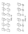
- spatial scalability two other forms of scalability are defined: signal-to-noise (SNR) scalability and spatial scalability.
- SNR scalability implies the creation of multi-rate bit streams. It allows for the recovery of coding errors, or differences between an original picture and its reconstruction. This is achieved by using a finer quantiser to encode the difference picture in an enhancement layer. This additional information increases the SNR of the overall reproduced picture.
- Spatial scalability allows for the creation of multi-resolution bit streams to meet varying display requirements and/or constraints.
- a spatially scalable structure is illustrated in Figure 11 . It is essentially the same as in SNR scalability except that a spatial enhancement layer attempts to recover the coding loss between an up-sampled version of the reconstructed reference layer picture and a higher resolution version of the original picture. For example, if the reference layer has a quarter common intermediate format (QCIF) resolution, and the enhancement layer has a common intermediate format (CIF) resolution, the reference layer picture must be scaled accordingly such that the enhancement layer picture can be predicted from it.
- QCIF quarter common intermediate format
- CIF common intermediate format
- the QCIF standard allows the resolution to be increased by a factor of two in the vertical direction only, horizontal direction only, or both the vertical and horizontal directions for a single enhancement layer.
- the interpolation filters used to up-sample the reference layer picture are explicitly defined in the H.263 standard. Aside from the up-sampling process from the reference to the enhancement layer, the processing and syntax of a spatially scaled picture are identical to those of an SNR scaled picture.
- the enhancement layer pictures are referred to as EI- or EP-pictures. If the enhancement layer picture is upwardly predicted from a picture in the reference layer, then the enhancement layer picture is referred to as an Enhancement-I (EI) picture.
- EI Enhancement-I
- the reference layer means the layer "below" the current enhancement layer.
- forward prediction is permitted In the enhancement layer.
- a picture that can be predicted in the forward direction from a previous enhancement layer picture or, alternatively, upwardly predicted from the reference layer picture is referred to as an Enhancement-P (EP) picture.
- EP Enhancement-P
- computing the average of the upwardly and forwardly predicted pictures can provide bi-directional prediction for EP-pictures.
- upward prediction from the reference layer picture implies that no motion vectors are required.
- forward prediction for EP-pictures motion vectors are required.
- the SRPN field can be associated with P, PB, Improved PB, and Enhancement Layer (EP) pictures.
- P Physical Transport Layer
- EP Enhancement Layer
- the characteristics of PB and Improved PB frames are described in H.263 Annex G and Annex M respectively.
- the SRPN is not used.
- the message typically concerns only the P-part.
- the message is used for forward prediction, whereas upward prediction is done from the temporally corresponding reference layer picture. This message preferably is not used if the picture is an I, El or B picture.
- each layer has consecutive Spare Reference Picture Numbers. These may be associated with the enhancement layer number (ELNUM) of the current picture.
- the Spare Reference Picture Number is incremented by one from the corresponding number of the previous coded reference picture in the same enhancement layer.
- the decoder preferably regards this as an indication that redundant copies have been sent of approximately the same pictured scene content, and all of these pictures then share the same Picture Numnber.
- an SRPN for a specified rectangular area of the current picture.
- a decoder can use error concealment to conceal errors in those areas if the corresponding reference frame (or area thereof) from which they are predicted cannot be decoded.
- the decoder preferably uses a concealment method that corresponds to the picture type i.e. for an INTRA picture an INTRA error concealment method is used and for an INTER picture an INTER error concealment method is used.
- Each SRPN message comprises an SRPN and four PSUPP octets containing the horizontal and vertical location of the upper left corner of the specified rectangular area of the picture, and the width an height of the rectangular area, respectively, using eight bits each and expressed in units of 16 pixels (of luminance picture). For example, using this convention, an entire QCIF picture is specified by the four parameters (0, 0, 11, 9).
- the specified area may extend to the next larger size that would be divisible by 16.
- an entire image having size of 160 x 120 pixels is specified by the four parameters (0, 0, 10, 8).
- the specified area does not cross picture boundaries nor overlap with other specified error concealment areas of the same picture.
- the invention may be implemented in other video coding protocols.
- MPEG-4 defines so-called user data, which can contain any binary data and is not necessarily associated with a picture.
- the additional field may be added to these fields.
- the invention is not intended to be limited to the video coding protocols discussed above: these are intended to be merely exemplary.
- the invention is applicable to any video coding protocol using temporal prediction.
- the addition of the information as discussed above allows a receiving decoder to determine the best cause of action if a.picture is lost.
Abstract
- determining that a corresponding area of a default reference picture, for use in forming a motion compensated prediction for an area of a current picture, has been corrupted or lost;
- examining an indicator provided in the encoded video signal to identify an area of an alternative reference picture that is sufficiently similar to the corresponding area of the default reference picture; and
- forming a motion compensated prediction for the area of the current picture using the identified sufficiently similar area of the alternative reference picture.
Description
- This invention relates to video coding.
- A video sequence consists of a series of still pictures or frames. Video compression methods are based on reducing the redundant and perceptually irrelevant parts of video sequences. The redundancy in video sequences can be categorised into spectral, spatial and temporal redundancy. Spectral redundancy refers to the similarity between the different colour components of the same picture. Spatial redundancy results from the similarity between neighbouring pixels in a picture. Temporal redundancy exists because objects appearing in a previous image are also likely to appear in the current image. Compression can be achieved by taking advantage of this temporal redundancy and predicting the current picture from another picture, termed an anchor or reference picture. Further compression is achieved by generating motion compensation data that describes the motion between the current picture and the previous picture.
- However, sufficient compression cannot usually be achieved by only reducing the inherent redundancy of the sequence. Thus, video encoders also try to reduce the quality of those parts of the video sequence which are subjectively less important. In addition, the redundancy of the encoded bit-stream is reduced by means of efficient lossless coding of compression parameters and coefficients. The main technique is to use variable length codes.
- Video compression methods typically differentiate between pictures that utilise temporal redundancy reduction and those that do not. Compressed pictures that do not utilise temporal redundancy reduction methods are usually called INTRA or I-frames or I-pictures. Temporally predicted images are usually forwardly predicted from a picture occurring before the current picture and are called INTER or P-frames. In the INTER frame case, the predicted motion-compensated picture is rarely precise enough and therefore a spatially compressed prediction error frame is associated with each INTER frame. INTER pictures may contain INTRA-coded areas.
- Many video compression schemes also use temporally bi-directionally predicted frames, which are commonly referred to as B-pictures or B-frames. B-pictures are inserted between anchor picture pairs of I- and/or P-frames and are predicted from either one or both of these anchor pictures. B-pictures, normally yield increased compression as compared with forward-predicted pictures. B-pictures are not used as anchor pictures, i.e., other pictures are not predicted from them. Therefore they can be discarded (Intentionally or unintentionally) without impacting the picture quality of future pictures. Whilst B-pictures may improve compression performance as compared with P-pictures, their generation requires greater computational complexity and memory usage, and they introduce additional delays. This may not be a problem for non-real time applications such as video streaming but may cause problems in real-time applications such as video-conferencing,
- A compressed video clip typically consists of a sequence of pictures, which can be roughly categorised into temporally Independent INTRA pictures and temporally differentially coded INTER pictures. Since the compression efficiency in INTRA pictures is normally lower than in INTER pictures, INTRA pictures are used sparingly, especially In low bit-rate applications.
- A video sequence may consist of a number of scenes or shots. The picture contents may be remarkably different from one scene to another, and therefore the first picture of a scene is typically INTRA-coded. There are frequent scene changes in television and film material, whereas scene cuts are relatively rare in video conferencing. In addition, INTRA pictures are typically inserted to stop temporal propagation of transmission errors in a reconstructed video signal and to provide random access points to a video bit-stream.
- Compressed video is easily corrupted by transmission errors, mainly for two reasons. Firstly, due to utilisation of temporal predictive differential coding (INTER frames), an error is propagated both spatially and temporally. In practice this means that, once an error occurs, it is easily visible to the human eye for a relatively long time. Especially susceptible are transmissions at low bit-rates where there are only a few INTRA-coded frames, so temporal error propagation is not stopped for some time. Secondly, the use of variable length codes increases the susceptibility to errors. When a bit error alters the codeword, the decoder will lose codeword synchronisation and also decode subsequent error-free codewords (comprising several bits) incorrectly until the next synchronisation (or start) code. A synchronisation code is a bit pattern which cannot be generated from any legal combination of other codewords and such codes are added to the bit stream at intervals to enable re-synchronisation. In addition, errors occur when data is lost during transmission. For example, in video applications using the unreliable UDP transport protocol in IP networks, network elements may discard parts of the encoded video bit-stream.
- There are many ways for the receiver to address the corruption introduced in the transmission path. In general, on receipt of a signal, transmission errors are first detected and then corrected or concealed by the receiver. Error correction refers to the process of recovering the erroneous data perfectly as if no errors had been introduced in the first place. Error concealment refers to the process of concealing the effects of transmission errors so that they are hardly visible in the reconstructed video sequence. Typically some amount of redundancy is added by the source or transport coding in order to help error detection, correction and concealment.
- There are numerous known concealment algorithms, a review of which is given by Y. Wang and Q. -F. Zhu in "Error Control and Concealment for Video Communication: A Review", Proceedings of the IEEE, Vol. 86, No. 5, May 1998, pp. 974 - 997 and an article by P. Salama, N. B. Shroff, and E. J. Delp, "Error Concealment in Encoded Video," submitted to IEEE Journal on Selected Areas in Communications.
- Current video coding standards define a syntax for a self-sufficient video bit-stream. The most popular standards at the time of writing are ITU-T Recommendation H.263, "Video coding for low bit rate communication", February 1998; ISO/IEC 14496-2, "Generic Coding of Audio-Visual Objects. Part 2: Visual", 1999 (known as MPEG-4); and ITU-T Recommendation H.262 (ISO/IEC 13818-2) (known as MPEG-2). These standards define a hierarchy for bit-streams and correspondingly for image sequences and images.
- In H.263, the hierarchy has four layers: picture, picture segment, macroblock, and block layer. The picture layer data contain parameters affecting the whole picture area and the decoding of the picture data. Most of this data is arranged in a so-called picture header.
- The picture segment layer can either be a group of blocks layer or a slice layer. By default, each picture is divided into groups of blocks. A group of blocks (GOB) typically comprises 16 successive pixel lines. Data for each GOB consists of an optional GOB header followed by data for macroblocks. If the optional slice structured mode is used, each picture is divided into slices instead of GOBs, A slice contains a number of successive macroblocks in scan-order. Data for each slice consists of a slice header followed by data for the macroblocks.
- Each GOB or slice is divided into macroblocks. A macroblock relates to 16 x 16 pixels (or 2 x 2 blocks) of luminance and the spatially corresponding 8 x 8 pixels (or block) of chrominance components. A block relates to 8 x 8 pixels of luminance or chrominance.
- Block layer data consist of uniformly quantised discrete cosine transform coefficients, which are scanned in zigzag order, processed with a run-length encoder and coded with variable length codes. MPEG-2 and MPEG-4 layer hierarchies resemble the one in H.263.
- By default, these standards use the temporally previous anchor (I, EI, P, or EP) picture as a reference for temporal prediction. This piece of information is not transmitted, i.e. the bit-stream does not contain information relating to the identity of the reference picture. Consequently, decoders have no means to detect if a reference picture is lost. Many transport coders packetise video data in such a way that they associate a sequence number with the packets. However, these kinds of sequence numbers are not related to the video bit-stream. For example, a section of a video bit-stream may contain the data for P-picture P1, B-picture B2, P-picture P3, and P-picture P4 captured (and to be displayed) in this order. However, this section of the video bitstream would be compressed, transmitted, and decoded in the following order: P1, P3, B2, P4 since B2 requires both P1 and P3 before it can be encoded or decoded. Let us assume that there is one packet per one picture and each packet contains a sequence number. Let us further assume that the packet carrying B2 is lost. The receiver can detect this loss from the packet sequence numbers. However, the receiver has no means to detect. if it has lost a motion compensation reference picture for P4 or if it has lost a B-picture, in which case it could continue decoding normally.
- The decoder therefore usually sends an INTRA request to the transmitter and freezes the picture on the display. However the transmitter may not be able to respond to this request. For instance in a non-real-time video streaming application, the transmitter cannot respond to an INTRA request from a decoder. Therefore the decoder freezes the picture until the next INTRA frame is received. In a real-time application such as video-conferencing, the transmitter may not be able to respond. For instance, in a multi-party conference, the encoder may not be able to respond to individual requests. Again the decoder freezes the picture until an INTRA frame is output by the transmitter.
- According to a first aspect of the invention there is provided a method of encoding a video signal representing a sequence of pictures, the method comprising receiving a current picture for encoding, forming a temporal prediction of the current picture from a default reference picture for the current picture, comparing the default reference picture with at least one further reference picture, calculating a measure of the similarity between the default reference picture and each further reference picture and, if the measure of similarity meets a pre-determined criterion, outputting an indicator identifying the further reference picture and associating the indicator with the temporal prediction of the current frame.
- Encoders can use this indicator to instruct decoders which pictures resemble the current motion compensation reference picture so well that one of them can be used as a spare reference picture if the actual reference picture is lost during transmission. If a decoder lacks an actual reference picture but can access a spare reference picture, preferably the decoder should not send a request for an INTRA picture update. The indicator may be termed a spare reference picture number since the indicator indicates to a decoder which reference picture(s) resemble the default reference picture. This "spare" reference picture may be used by a decoder to decode the current frame if the default reference picture is lost for some reason.
- The spare reference picture number may be in respect of the whole picture or part of a picture. In the former case, typically the spare reference picture number is included in a picture header. In the latter case the spare reference picture number is included in the picture segment headers or macroblock headers of the picture. In a preferred implementation of the invention, the video signal is encoded according to the H.263 standard and the indicator is included in the Supplemental Enhancement Information.
- Preferably the method also comprises forming a temporal prediction of the current picture from a first default reference picture and a second default reference picture for the current picture, said first default reference picture occurring temporally before the current picture and said second default reference picture occurring temporally after the current picture, comparing the first default reference picture with at least one further reference picture occurring temporally before the current picture, calculating a measure of the similarity between the first default reference picture and each further reference picture and, if the measure of similarity meets a pre-determined criterion, outputting an indicator identifying the further reference picture.
- Thus an indicator is provided for forwardly predicted frames but not for backwardly predicted frames.
- Preferably the default reference picture is compared with a plurality of further reference pictures and an indicator is output for each further reference picture that meets the predetermined criterion. Advantageously the further reference pictures that meet the predetermined criterion are linked in order of similarity and the indicator is associated with the temporal prediction of the current frame in order of rank, the further reference picture having the closest similarity to the default reference picture being placed first. The comparison may be carried out for portions of a picture at a time e.g. blocks or other non-rectangular areas of the pictures.
- According to a second aspect of the invention there is provided a method of encoding a video signal representing a sequence of pictures, the method comprising receiving a current picture for encoding, forming a prediction of at least part of the current picture from a default reference picture for the current picture, comparing the part of the default reference picture or the current picture with a corresponding part of at least one further picture of the sequence to form a measure of similarity and, if the measure of similarity meets a pre-determined criterion, outputting an indicator in respect of the part of the current frame Identifying the further picture of the sequence.
- According to a third aspect of the Invention there is provided a method of decoding an encoded video signal representing a sequence of pictures, the encoded signal including pictures that have been encoded by forming a temporal prediction of a current picture from a default reference picture for the current picture, the method comprising receiving an encoded video signal representing a current picture and decoding at least the picture header of the current picture wherein, when the decoder Is unable to decode the default reference picture of the current picture, examining an indicator Identifying a further reference picture and decoding the current picture with reference to said further reference picture if such an indicator is associated with the current picture.
- According to a fourth aspect of the invention there is provided a video encoder comprising an input for receiving a video signal representing a sequence of pictures, an input for receiving a current picture for encoding, a predictive coder for forming a temporal prediction of the current picture from a default reference picture for the current picture, a comparator for comparing the default reference picture or the current picture with at least one further reference picture and calculating a measure of the similarity and, when the measure of similarity meets a pre-determlned criterion, outputting an indicator identifying the further reference picture.
- According to a fifth aspect of the invention there is provided a video decoder comprising an input for receiving an encoded video signal representing a sequence of pictures, the encoded signal including pictures that have been encoded by forming a temporal prediction of a current picture from a default reference picture for the current picture, the decoder comprising an Input for receiving an encoded video signal representing a current picture and a processor for decoding at least the picture header of the current picture wherein, when the decoder is unable to decode the default reference picture of the current picture, the decoder is arranged to examine an indicator identifying a further reference picture and to decode the current picture with reference to said further reference picture if such an indicator is associated with the current picture.
- There is also disclosed the following in the numbered paragraphs below on pages 9a-17a:
- 1. A method for encoding a video signal to form an encoded video signal, the video signal representing a sequence of pictures, the method comprising:
- obtaining a default reference picture by encoding and decoding a picture of the sequence;
- forming a motion compensated prediction for an area of a current picture of the sequence using a corresponding area of the default reference picture;
- generating an indicator identifying an alternative reference picture, which comprises an area sufficiently similar to the corresponding area of the default reference picture, for use in forming a motion compensated prediction for the area of the current picture when the encoded video signal representing the corresponding area of the default reference picture received in a corresponding decoding process is corrupted or lost; and
- providing the indicator in the encoded video signal.
- 2. A method according to
paragraph 1, comprising:- identifying the alternative reference picture by comparing the corresponding area of the default reference picture with a further reference picture to calculate a measure of similarity between the two;
- comparing the measure of similarity against a pre-determined similarity criterion; and
- generating the indicator based on the comparison.
- 3. A method according to
paragraph 2, comprising:- identifying more than one alternative reference picture which comprises an area sufficiently similar to the corresponding area of the default reference picture by comparing the corresponding area of the default reference picture with a plurality of further reference pictures to calculate respective measures of similarity; and
- providing an indicator for each further reference picture that meets a predetermined similarity criterion.
- 4. A method according to
paragraph 3, comprising ranking the further reference pictures based on said comparison and providing more than one indicator in the encoded video signal according to a ranking order, the indicator associated with the further reference picture having an area with the closest similarity to the corresponding area of the default reference picture being placed first in the ranking order. - 5. A method according to
paragraph 1, comprising providing the indicator in Supplemental Enhancement Information of the encoded video signal. - 6. A method according to
paragraph 1, comprising generating the indicator to indicate one of a temporal reference of the alternative reference picture or a picture number of the alternative reference picture. - 7. A method according to
paragraph 1, comprising providing respective indicators to indicate corresponding alternative reference pictures for B pictures and P pictures. - 8. A method according to
paragraph 1, comprising providing indicators to indicate alternative reference pictures only for P pictures. - 9. A method according to
paragraph 2, comprising calculating the measure of similarity as a sum of absolute differences using differences in pixel values between the corresponding area of the default reference picture and the further reference picture. - 10. A method according to
paragraph 2, comprising calculating the measure of similarity between the corresponding area of the default reference picture and the further reference picture using picture histograms. - 11. A method according to
paragraph 1, wherein the area of the current picture is the whole of the current picture or a part of the current picture. - 12. A method for decoding an encoded video signal representing a sequence of pictures, the method comprising:
- determining that a corresponding area of a default reference picture, for use in forming a motion compensated prediction for an area of a current picture, has been corrupted or lost:
- examining an indicator provided in the encoded video signal to identify an area of an alternative reference picture that is sufficiently similar to the corresponding area of the default reference picture; and
- forming a motion compensated prediction for the area of the current picture using the identified sufficiently similar area of the alternative reference picture.
- 13. A method according to
paragraph 12, comprising:- examining a ranking order of more than one indicator provided in the encoded video signal to identify respective areas of more than one alternative reference pictures that are sufficiently similar to the corresponding area of the default reference picture that has been corrupted or lost;
- selecting an indicator based on the ranking order; and
- forming a motion compensated prediction for the area of the current picture using the sufficiently similar area of the alternative reference picture identified by the selected indicator.
- 14. A method according to
paragraph 12, comprising obtaining the indicator from Supplemental Enhancement Information of the encoded video signal. - 15. A method according to
paragraph 12, comprising using the indicator to identify one of a temporal reference of the alternative reference picture or a picture number of the alternative reference picture. - 16. A method according to
paragraph 12, comprising using respective indicators to identify corresponding alternative reference pictures for B pictures and P pictures. - 17. A method according to
paragraph 12, comprising using respective indicators to identify corresponding alternative reference pictures only for P pictures. - 18. A method according to
paragraph 12, wherein the area of the default reference picture that is corrupted or lost is either the whole of the default reference picture or a part of the default reference picture. - 19. An encoder for encoding a video signal to form an encoded video signal, the video signal representing a sequence of pictures, wherein the encoder is arranged to:
- obtain a default reference picture by encoding and decoding a picture of the sequence;
- form a motion compensated prediction for an area of a current picture of the sequence using a corresponding area of the default reference picture;
- generate an indicator identifying an alternative reference picture, which comprises an area sufficiently similar to the corresponding area of the default reference picture, for use in forming a motion compensated prediction for the area of the current picture when the encoded video signal representing the corresponding area of the default reference picture received in a corresponding decoding process is corrupted or lost; and
- provide the indicator in the encoded video signal.
- 20. An encoder according to
paragraph 19, wherein the encoder is arranged to:- identify the alternative reference picture by comparing the corresponding area of the default reference picture with a further reference picture to calculate a measure of similarity between the two;
- compare the measure of similarity against a pre-determined similarity criterion; and
- generate the indicator based on said comparison.
- 21. An encoder according to
paragraph 20, wherein the encoder is arranged to:- identify more than one alternative reference picture which comprises an area sufficiently similar to the corresponding area of the default reference picture by comparing the corresponding area of the default reference picture with a plurality of further reference pictures to calculate respective measures of similarity; and
- provide an indicator for each further reference picture that meets a predetermined similarity criterion.
- 22. An encoder according to
paragraph 21, wherein the encoder is arranged to rank the further reference pictures based on said comparison and to provide more than one indicator in the encoded video signal according to a ranking order, the indicator associated with the further reference picture having an area with the closest similarity to the corresponding area of the default reference picture being placed first in the ranking order. - 23. An encoder according to
paragraph 19, wherein the encoder is arranged provide the indicator in Supplemental Enhancement Information of the encoded video signal. - 24. An encoder according to
paragraph 19, wherein the encoder is arranged to generate the indicator to indicate one of a temporal reference of the alternative reference picture or a picture number of the alternative reference picture. - 25. An encoder according to
paragraph 19, wherein the encoder is arranged to provide respective indicators to indicate corresponding alternative reference pictures for B pictures and P pictures. - 26. An encoder according to
paragraph 19, wherein the encoder is arranged to provide indicators to indicate alternative reference pictures only for P pictures. - 27. An encoder according to
paragraph 20, wherein the encoder is arranged to calculate the measure of similarity as a sum of absolute differences using differences in pixel values between the corresponding area of the default reference picture and the further reference picture. - 28. An encoder according to
paragraph 20, wherein the encoder is arranged to calculate the measure of similarity between the corresponding area of the default reference picture and the further reference picture using picture histograms. - 29. An encoder according to
paragraph 19, wherein the area of the current picture is the whole of the current picture or a part of the current picture. - 30. A decoder for decoding an encoded video signal representing a sequence of pictures, wherein the decoder is arranged to:
- determine that a corresponding area of a default reference picture, for use in forming a motion compensated prediction for an area of a current picture has been corrupted or lost;
- examine an indicator provided in the encoded video signal to identify an area of an alternative reference picture that is sufficiently similar to the corresponding area of the default reference picture; and
- form a motion compensated prediction for the area of the current picture using the identified sufficiently similar area of the alternative reference picture.
- 31. A decoder according to
paragraph 30, wherein the decoder is arranged to:- examine a ranking order of more than one indicator provided in the encoded video signal to identify respective areas of more than one alternative reference pictures that are sufficiently similar to the corresponding area of the default reference picture that has been corrupted or lost;
- select an indicator based on the ranking order; and
- form a motion compensated prediction for the area of the current picture using the sufficiently similar area of the alternative reference picture identified by the selected indicator.
- 32. A decoder according to
paragraph 30, wherein the decoder is arranged to obtain the indicator from Supplemental Enhancement Information of the encoded video signal. - 33. A decoder according to
paragraph 30, wherein the decoder is arranged to use the Indicator to identify one of a temporal reference of the alternative reference picture or a picture number of the alternative reference picture. - 34. A video decoder according to
paragraph 30, wherein the decoder is arranged to use respective indicators to identify corresponding alternative reference pictures for B pictures and P pictures. - 35. A video decoder according to
paragraph 30, wherein the decoder is arranged to use respective indicators to identify corresponding alternative reference pictures only for P pictures. - 36. A method according to
paragraph 30, wherein the area of the default reference picture that is corrupted or lost is either the whole of the default reference picture or a part of the default reference picture. - 37. A radio telecommunications device comprising an encoder according to any of
paragraphs 19 to 29. - 38. A radio telecommunications device comprising a decoder according to any of
paragraphs 30 to 36. - 39. A multimedia terminal device comprising an encoder according to any of
paragraphs 19 to 29. - 40. A multimedia terminal device comprising a decoder according to any of
paragraphs 30 to 36. - 41. An encoded video signal representing a sequence of pictures, the encoded video signal comprising an indicator identifying an alternative reference picture, which comprises an area sufficiently similar to a corresponding area of a default reference picture, for use in forming a motion compensated prediction for the area of the current picture when the encoded video signal representing the corresponding area of the default reference picture received in a corresponding decoding process is corrupted or lost.
- 42. Computer program for encoding for encoding a video signal to form an encoded video signal, the video signal representing a sequence of pictures, the computer program comprising code for:
- obtaining a default reference picture by encoding and decoding a picture of the sequence;
- forming a motion compensated prediction for an area of a current picture of the sequence using a corresponding area of the default reference picture;
- generating an indicator identifying an alternative reference picture, which comprises an area sufficiently similar to the corresponding area of the default reference picture, for use in forming a motion compensated prediction for the area of the current picture when the encoded video signal representing the corresponding area of the default reference picture received in a corresponding decoding process is corrupted or lost; and
- providing the indicator in the encoded video signal.
- 43. Computer program for decoding an encoded video signal representing a sequence of pictures, the computer program comprising code for:
- determining that a corresponding area of a default reference picture, for use in forming a motion compensated prediction for an area of a current picture, has been corrupted or lost;
- examining an indicator provided in the encoded video signal to identify an area of an alternative reference picture that is sufficiently similar to the corresponding area of the default reference picture; and
- forming a motion compensated prediction for the area of the current picture using the identified sufficiently similar area of the alternative reference picture.
- There is also disclosed the following in the numbered paragraphs below on pages 18a-20a:
- 1. A method of encoding a video signal representing a sequence of pictures, the method comprising receiving a current picture for encoding, forming a temporal prediction of the current picture from a default reference picture for the current picture, comparing the default reference picture with at least one further reference picture, calculating a measure of the similarity between the default reference picture and each further reference picture and, if the measure of similarity meets a pre-determined criterion, outputting an indicator identifying the further reference picture.
- 2. A method according to
paragraph 1 further comprising forming a temporal prediction of the current picture from a first default reference picture and a second default reference picture for the current picture, said first default reference picture occurring temporally before the current picture and said second default reference picture occurring temporally after the current picture, comparing the first default reference picture with at least one further reference picture occurring temporally before the current picture, calculating a measure of the similarity between the first default reference picture and each further reference picture and, if the measure of similarity meets a pre-determined criterion, outputting an indicator identifying the further reference picture. - 3. A method according to
paragraph - 4. A method according to
paragraph 3 further comprising ranking the further reference pictures that meet the predetermined criterion and associating the indicator with the temporal prediction of the current frame in order of rank, the further reference picture having the closest similarity to the default reference picture being placed first. - 5. A method according to any preceding paragraph wherein the indicator is included in a picture header.
- 6. A method according to any preceding paragraph wherein the video signal is encoded according to the H.263 video compression standard and the indicator is included in the Supplemental Enhancement Information.
- 7. A method according to any preceding paragraph wherein the comparison is carried out for portions of a picture at a time.
- 8. A method of encoding a video signal representing a sequence of pictures, the method comprising receiving a current picture for encoding, forming a prediction of at least part of the current picture from a default reference picture for the current picture, comparing the part of the default reference picture or the current picture with a corresponding part of at least one further picture of the sequence to form a measure of similarity and, if the measure of similarity meets a pre-determined criterion, outputting an indicator in respect of the part of the current frame identifying the further picture of the sequence.
- 9. A method of decoding an encoded video signal representing a sequence of pictures, the encoded signal including pictures that have been encoded by forming a temporal prediction of a current picture from a default reference picture for the current picture, the method comprising receiving an encoded video signal representing a current picture and decoding at least the picture header of the current picture wherein, when the decoder is unable to decode the default reference picture of the current picture, examining an indicator identifying a further reference picture and decoding the current picture with reference to said further reference picture if such an indicator is associated with the current picture.
- 10. A video encoder comprising an input for receiving a video signal representing a sequence of pictures, an input for receiving a current picture for encoding, a predictive coder for forming a temporal prediction of the current picture from a default reference picture for the current picture, a comparator for comparing the default reference picture or the current picture with at least one further reference picture and calculating a measure of the similarity and, when the measure of similarity meets a pre-determined criterion, outputting an indicator identifying the further reference picture,
- 11. A video decoder comprising an input for receiving an encoded video signal representing a sequence of pictures, the encoded signal including pictures that have been encoded by forming a temporal prediction of a current picture from a default reference picture for the current picture, the decoder comprising an input for receiving an encoded video signal representing a current picture and a processor for decoding at least the picture header of the current picture wherein, when the decoder is unable to decode the default reference picture of the current picture, the decoder is arranged to examine an indicator identifying a further reference picture and to decode the current picture with reference to said further reference picture if such an indicator is associated with the current picture.
- 12. A radio telecommunications device including an encoder according to
paragraph 10 and/or a decoder according toparagraph 11. - The invention also relates to a radio telecommunications device including an encoder and/or a decoder as described.
- The Invention will now be described, by way of example only, with reference to the accompanying drawings, in which:
-
Figure 1 shows a multimedia mobile communications system; -
Figure 2 shows an example of the multimedia components of a multimedia terminal; -
Figure 3 shows an example of a video codec; -
Figure 3a shows a more detailed view of a video encoder according to the invention; -
Figure 4 illustrates the operation of a first embodiment of a video encoder according to the invention; -
Figure 5 illustrates the operation of a second implementation of a video encoder according to the invention; -
Figure 6 shows the syntax of a bit stream as known according to H.263; -
Figure 7 shows a first example of a bit stream output by an encoder according to the invention; -
Figure 8 shows a second example of a bit stream output by an encoder according to the invention; -
Figure 9 shows a third example of a bit stream output by an encoder according to the invention; -
Figure 10 Illustrates enhancement layers used in video coding for SNR scalability; and -
Figure 11 illustrates enhancement layers used in video coding for spatial scalability. -
Figure 1 shows a typical multimedia mobile communications system. A first multimediamobile terminal1 1 communicates with a second multimediamobile terminal 2 via aradio link 3 to amobile communications network 4. Control data is sent between the twoterminals -
Figure 2 shows the typical multimedia components of aterminal 1. The terminal comprises avideo codec 10, anaudio codec 20, adata protocol manager 30, acontrol manager 40, a multiplexer/demultiplexer 50 and a modem 60 (if the required). Thevideo codec 10 receives signals for coding from a video capture device of the terminal (not shown) (e.g. a camera) and receives signals for decoding from aremote terminal 2 for display by theterminal 1 on adisplay 70. Theaudio codec 20 receives signals for coding from the microphone (not shown) of theterminal 1 and receives signals for decoding from aremote terminal 2 for reproduction by a loudspeaker (not shown) of theterminal 1. The terminal may be a portable radio communications device, such as a radio telephone. - The
control manager 40 controls the operation of thevideo codec 10, theaudio codec 20 and thedata protocols manager 30. However, since the invention is concerned with the operation of thevideo codec 10, no further discussion of theaudio codec 20 anddata protocols manager 30 will be provided. -
Figure 3 shows an example of avideo codec 10 according to the invention. - The video codec comprises an
encoder part 100 and adecoder part 200. Theencoder part 100 comprises aninput 101 for receiving a video signal from a camera or video source (not shown) of theterminal 1. Aswitch 102 switches the encoder between an INTRA-mode of coding and an INTER-mode. Theencoder part 100 of thevideo codec 10 comprises aDCT transformer 103, aquantiser 104, aninverse quantiser 108, aninverse DCT transformer 109, anadder 110, a plurality of picture stores 107 (seeFigure 3a for more detail), asubtractor 106 for forming a prediction error, aswitch 113 and anencoding control manager 105. - The
decoder part 200 of thevideo codec 10 comprises aninverse quantiser 120, aninverse DCT transformer 121, amotion compensator 122, a plurality ofpicture stores 123 and acontroller 124. Thecontroller 124 receives video codec control signals demultiplexed from the encoded multimedia stream by thedemultiplexer 50. In practice thecontroller 105 of the encoder and thecontroller 124 of the decoder may be the same processor. - The operation of an encoder according to the invention will now be described. The
video codec 10 receives a video signal to be encoded. Theencoder 100 of the video codec encodes the video signal by performing DCT transformation, quantisation and motion compensation. The encoded video data is then output to themultiplexer 50. Themultiplexer 50 multiplexes the video data from thevideo codec 10 and control data from the control 40 (as well as other signals as appropriate) into a multimedia signal. Theterminal 1 outputs this multimedia signal to the receivingteminal 2 via the modem 60 (if required). - In INTRA-mode, the video signal from the
input 101 is transformed to DCT co-efficients by aDCT transformer 103. The DCT coefficients are then passed to thequantiser 104 that quantises the coefficients. Both theswitch 102 and thequantiser 104 are controlled by theencoding control manager 105 of the video codec, which may also receive feedback control from the receivingterminal 2 by means of thecontrol manager 40. A decoded picture is then formed by passing the data output by the quantiser through theinverse quantiser 108 and applying an inverse DCT transform 109 to the inverse-quantised data. The resulting data is then input to theadder 110. In INTRA mode, theswitch 113 is set so that the input to theadder 110 from theswitch 113 is set to zero. The two inputs to theadder 110 are added together and the resulting data input to thepicture store 107. - In INTER mode, the
switch 102 is operated to accept from thesubtractor 106 the difference between the signal from theinput 101 and a reference picture which is stored in apicture store 107. The difference data output from thesubtractor 106 represents the prediction error between the current picture and the reference picture stored in thepicture store 107. Amotion estimator 111 may generate motion compensation data with reference to the data in thepicture store 107 in a conventional manner. - The
encoding control manager 105 decides whether to apply INTRA or INTER coding or whether to code the frame at all on the basis of either the output of thesubtractor 106 or in response to feedback control data from a receiving decoder. The encoding control manager may decide not to code a received frame at all when the similarity between the current frame and the reference frame is so high or there is not time to code the frame. The encoding control manager operates theswitch 102 accordingly, - When not responding to feedback control data, the encoder typically encodes a frame as an INTRA-frame either only at the start of coding (all other frames being P-frames), or at regular periods e.g. every 5s, or when the output of the subtractor exceeds a threshold i.e. when the current picture and that stored in the
picture store 107 are judged to be too dissimilar. The encoder may also be programmed to encode frames in a particular regular sequence e.g. I B B P B B P B B P B B P B B I B B P etc. - The video codec outputs the quantised
DCT coefficients 112a, the quantisingindex 112b (i.e. the details of the quantising used), an INTRA/INTER flag 112c to indicate the mode of coding performed (I or P/B), a transmit flag 112d to indicate the number of the frame being coded and (in INTER mode) themotion vectors 112e for the picture being coded. These are multiplexed together with other multimedia signals by themultiplexer 50. - The
encoder 100 will be described further with reference toFigure 3a , which shows a simplified view of theencoder 100 of the video codec. Theencoder 100 comprises a plurality ofpicture stores 107a-107g. Although in this example seven picture stores are shown, the number of picture stores may be two or more. - Consider an encoder that is arranged to encode an input signal with the format I B B P B B P B B P B B P B B P B B P B B I etc. For simplicity we will assume that the encoder will encode every frame of the input signal i.e. no frames will be skipped. This is illustrated in
Figure 4 . - As mentioned earlier, the frames are received from a video capture device in the
order order 10,B1,B2,P3,B4,B5,P6 etc. However the video bit stream is compressed, transmitted and decoded in the followingorder 10, P3, B1, B2, P6, 84, B5 etc. This is because each B-frame requires preceding and succeeding reference frames before it can be encoded/decoded i.e. frame B1 requires frame I0 and P3 to be encoded/decoded before it can be encoded/decoded. - When the first frame is received, all of the picture stores 107 are empty and the
switch 102 is placed into the INTRA mode under control of theencoding controller 105 so that the input signal is encoded in INTRA format. The input signal is DCT transformed and quantised. This is done on a macroblock by macroblock basis. The resulting signal is then decoded byinverse quantiser 108 andinverse DCT 109. Since the frame is INTRA coded,switch 113 is open. The output ofadder 110 is input to thefirst picture store 107a. For thispurpose switch 114a is closed whereasswitches 114b-g are open. Thusframe store 107a holds a decoded version ofreference picture 10. - The next picture to be coded is
frame 3, which is to be forwardly predicted from 10. Therefore whenframe 3 is input at 101, switch 102 Is changed to the INTER mode, the output switch 115 of the most recent reference picture store (i.e.switch 115a) is closed and the motion compensated contents ofpicture store 107a are subtracted from the input signal, motion compensation data having been calculated in the conventional manner, This prediction error is then encoded byDCT 103 and quantiser 104 and decoded byinverse quantiser 108 andIDCT 109. Theswitch 113 is then closed, switch 115a closed andswitch 114b closed (the other switches 114 and 115 being open), Thus adder 110 adds the decoded picture to the picture as stored inpicture store 107a and stores the result inpicture store 107b. - The next frame to be coded is
frame 2, which is to be coded as a B-frame. Thus the contents of both of theframe stores subtractor 106 in a conventional manner, Since B-frames do not form a reference picture for any other frame, the encoded B-frame is not decoded and stored in a reference picture store. - Thus in the case described above, after 19 frames, the
frame stores 107a to 107g contain decoded versions offrames 10, P3, P6, P9, P12, P15 and P18 respectively. - In the invention, when the encoder encodes a frame in a predictive manner, the
encoding control manager 105 may associate with the frame a Spare Reference Picture Number (SRPN). For example, a SRPN may be associated with the P and B frames of a video signal but not with the I-frames. - Encoders can use this message to instruct decoders which reference picture or pictures resemble the current reference picture, so that one of them can be used as a spare reference picture if the actual reference picture is lost during transmission.
- When
frame 3 is encoded with reference toframe 0, no other reference frames are stored In thereference picture stores 107a-g. Therefore no SRPN is associated withframe 3. Similarly when frames 1 and 2 are bi-directionally encoded with reference toframes reference picture stores 107a-g. Therefore no SRPN is associated with either of these frames. - However when
frame 6 is forwardly predicted from frame 3 (the decoded version of which is stored inpicture store 107b) there is also a decoded copy offrame 10 inpicture store 107a. The encoder calculates the similarity between the default reference picture of the current frame (i.e.frame 3 for frame 6) and the contents of the other populated picture stores i.e.picture store 107a. If two reference pictures are sufficiently similar (e.g. the correlation between the contents offrame store frame 6. The SRPN identifiesframe 0 as a spare reference picture. However, if the similarity is not sufficient, no SRPN is associated withframe 6. - The way in which the measure of similarity is generated is not material to the invention and any suitable measure of similarity may be used. For instance, a Sum of Absolute Differences (SAD) may be used as a measure of similarity. Preferably, an SAD value is calculated by taking the difference in value between spatially corresponding pixels in the default reference picture for the current frame and another "potential" reference frame i.e. a frame stored in one of the picture stores 107. The absolute value of each difference is obtained and the absolute difference values are accumulated to form the SAD. In this way, the SAD is representative of the similarity between the default reference frame and the other potential reference frame. Clearly two pictures can be deemed sufficiently similar when the SAD between them is below a threshold. Alternatively, the similarity of the default reference frame and another potential reference frame for the current picture can be assessed using picture histograms. A picture histogram is a measure of the number of occurrences of pixel values within a given image and two pictures can be deemed similar if their histograms correspond to a significant degree.
- In an alternative embodiment of the invention, instead of determining the similarity between the default reference frame for the current frame and another potential reference frame, the encoder examines the similarity between another potential reference frame available in one of the picture stores 107 and the current frame itself. In this alternative embodiment of the invention a threshold is set defining the maximum difference allowable between the current frame and the potential reference frame. Thus any stored frame which exhibits a sufficiently high similarity (small difference) with the current frame can be used as a spare reference picture for the current picture. Again a Sum of Absolute Differences (SAD), image histogram, or any other appropriate method can be used to assess the degree of similarity / difference between the current frame and the other potential reference frame(s).
- As will be appreciated, when
frame 15 is to be encoded (as a P-frame), decoded versions offrames picture stores 114a-e respectively. By default,frame 15 is encoded with reference to frame 12 as stored inpicture store 107e. The encoder also carries out a calculation of the correlation between the data in thepicture store 107e and the data stored in the otherpopulated picture stores 107a-d. The encoder identifies the picture store (and hence the reference picture) that has the closest correlation with the contents ofpicture store 107e i.e. with the default reference picture for the current frame being coded. The encoder than adds a SRPN to the encoded data that indicates the identified reference picture. This SRPN can be equal to the Temporal Reference of the reference picture as will be described below. - More than one SRPN may be associated with a frame. In this case the SRPN are ordered within the picture header in the order of similarity, the most similar reference picture (other than the default) being mentioned first.
- The
encoding control manager 105 outputs this SRPN codeword on output 112f which indicates the Spare Reference Picture Number associated with the encoded frame. This is multiplexed into the video bitstream by a multiplexer. -
Figure 4 illustrates the operation of a first embodiment of the encoder. The first line ofFigure 4 represents the frames of data received from a capture input device and input to the video coder oninput 101. The second line ofFigure 4 represents those frames of the input signal that the encoder decides to encode and the coding mode used to encode each frame. As mentioned above, in this example the encoder is arranged to encode every frame and to use the IBBP coding format. -
Frame 0 is coded in INTRA-mode;frame 1 is encoded as a B-frame with reference toframe 0 and/or 3;frame 2 is encoded as a B-frame with reference toframe 0 and/or 3;frame 3 is encoded as a P-frame with reference toframe 0;frame 4 is encoded as a B-frame with reference toframe 3 and/or 6;frame 5 is encoded as a B-frame with reference toframe 3 and/or 6;frame 6 is encoded as a P-frame with reference toframe 3; etc. - The third line of
Figure 4 shows a SRPN field associated with frames of the encoded signal. In this embodiment a SRPN is associated with the P-frames and B-frames, as shown in the third line ofFigure 4 . The P-frames and B-frames of the encoded frames are temporally predictively encoded and the I-frames are not. - The fourth line of
Figure 4 shows the Temporal Reference (TR) of the encoded frame. This is a field included in H.263 and the value of TR is formed by incrementing its value in the temporally previous reference picture header by one plus the number of skipped or non-reference pictures since the previously transmitted reference picture. Thus in the example shown inFigure 4 the TR shown for each frame is the same as the original temporal order of the frames in the original signal input to 101. - Examples of possible values of SRPN are shown. These values indicate the TR of the spare reference frame as identified by the encoder as described above. Although this example shows only one SRPN for each predictively encoded picture, more than one may be associated with each predictively encoded picture, as described earlier.
-
Figure 5 illustrates the operation of a second embodiment of an encoder according to the invention. In this embodiment, the encoder is arranged to code the frames according to the regular sequence I B B P B B P B B P B B I B B P B B P. However, in the embodiment, a SRPN is associated with forwardly predicted frames (i.e. P-frames) only. - The first line of
Figure 5 shows the input frames and the second line shows the coded frames and their coding mode, I, P or B. - The third line of
Figure 5 shows the SRPN associated with P-frames. These may be generated as discussed above with reference toFigure 3a . - The fourth line of
Figure 5 shows the Temporal Reference (TR) of the encoded frame. As in the example shown inFigure 4 , the TR shown for each frame is the same as the original temporal order of the frames in the original signal input to 101. - Considering the
terminal 1 as receiving coded video data fromterminal 2, the operation of thevideo codec 10 will now be described with reference to its decoding role. Theterminal 1 receives a multimedia signal from the transmittingterminal 2. Thedemultiplexer 50 demultiplexes the multimedia signal and passes the video data to thevideo codec 10 and the control data to thecontrol manager 40. Thedecoder 200 of the video codec decodes the encoded video data by inverse quantising, inverse DCT transforming and motion compensating the data. Thecontroller 124 of the decoder checks the integrity of the received data and, if an error is detected, attempts to conceal the error in a manner to be described below. The decoded, corrected and concealed video data is then stored in one of the picture stores 123 and output for reproduction on adisplay 70 of the receivingterminal 1. - Errors in video data may occur at the picture level, the GOB level or the macroblock level. Error checking may be carried out at any or each of these levels.
- Considering first the signal as shown in
Figure 4 , when a decoder according to the invention receives this signal each frame of the signal is decoded in a conventional manner and then displayed on a display means. The decoded frame may be error corrected and error coded in a conventional manner. Each time a frame is decoded, the decoder examines the TR field to determine when the frame is to be displayed. - In the case shown in
Figure 4 the decoder receivesframe 0 and determines from its picture header that the frame is INTRA-coded. The decoder decodesframe 0 without reference to any other picture and stores it in picture store 123a. The decoder then receivesframe 3 and determines from its picture header that the frame is INTER-coded as a P-frame. The decoder therefore decodesframe 3 with reference to the precedereference frame 0 and stores it in the next picture store 123b. The decoder then decodesframes frames - Let us now assume that the decoder is unable to decode (and thus reconstruct) frame 9 (this could be due to the data for
frame 9 being greatly corrupted or being lost altogether). The next frame received by the decoder is frame 7, with TR=7, and SRPN=0. As frame 9 (one of the default reference pictures for frame 7) was not decoded by the decoder, the decoder looks for a SRPN in the header of the received frame for the backward prediction. However, frame 7 does not include a SRPN in the backward direction. Therefore the decoder is unable to decode frame 7. This is also the case forframe 8. - The next frame to be received is
frame 12, which was encoded with reference topicture 9 and has SRPN=6. Sinceframe 9 was not decoded, the decoder uses the reference picture indicated by SRPN (i.e.frame 6 stored in picture store 123c) to decodeframe 12. The decoder then receivesframe 10, which was encoded with reference toframes Frame 9 was not decoded by the decoder. Howeverframe 10 has SRPN=6. Therefore the decoder uses the decodedreference frame 6, stored in picture store 123c, to decodeframe 10 in the forward direction, rather than frame 7. This is also true forframe 11. - The decoder may detect the omission of a reference frame in a number of ways, for instance information relating to the temporal order of each encoded frame may be examined. Alternatively, the reference frames of an encoded signal may be allocated a number in a sequential order as described in a British patent application filed by the Applicant on even date.
- If the decoder has the facility to send control feedback data to the transmitting video encoder the decoder can send a request to the transmitting video encoder to encode a frame as an INTRA-frame and so stop the temporal error propagation that would result from
frames frame 6. The decoder continues to decode the signal in a conventional manner. - When the decoder receives
frame 21, which is an INTRA frame, the decoder decodesframe 21 without reference to any other frame and stores the decoded frame inpicture store 123. The decoder then decodesframes frames frame 12 with reference tor_ frame 6 rather thanframe 9, the resulting image should be acceptable and the displayed picture is not held frozen until an INTRA picture is received. This may be more acceptable to a viewer. - Considering now the signal as shown in
Figure 5 , when a decoder according to the invention receives this signal each frame of the signal is decoded in a conventional manner and then displayed on a display means. The decoded frame may be error corrected and error concealed in a conventional manner. Each time a frame is decoded, the decoder examines the TR field to determine when the frame is to be displayed. - The decoder receives
frame 0, which is an INTRA frame and decodes it accordingly and stores it in picture store 123a. Let us now assume that the decoder is unable to reconstruct frame 3 (this could be due to the data being greatly corrupted or being lost altogether) and the next frame received and decoded by the decoder isframe 1.Frame 1 is a bi-directional frame encoded with reference toframe frame 3 is lost, the decoder is unable to reconstructframe 1 and similarly frame 2. The fact that B-frames - The next frame received and decoded by the decoder is
frame 6. The decoder knows that the preceding reference picture P3 has been lost (because it could not decodeframe 1 or 2). The decoder therefore examines the header of the received frame for an SRPN. The decoder determines thatframe 6 has a SRPN=0 and so usesframe 0 in the picture store 123a to decodeframe 6. - If the decoder has the facility to send control feedback data to the transmitting video encoder the decoder can send a request to the transmitting video encoder to encode a frame as an INTRA-frame and so stop the temporal error propagation that would result from subsequent frames being decoded with reference to
frame 6 which was decoded with reference toframe 0 rather than thedefault frame 3. However the decoder can continue decoding and does not freeze the picture on the display whilst it waits for an INTRA-coded frame. - How the spare reference picture number may be included in the encoded signal will now be addressed with reference to the H.263 video coding standard.
-
Figure 6 shows the syntax of a bit stream as known according to H.263. The following implementations describe the GOB format but it will be clear to a skilled person that the invention may also be implemented in the slice format. - As mentioned already, the bit stream has four layers: the picture layer, picture segment layer, macroblock layer and block layer. The picture layer comprises a picture header followed by data for the Group of Blocks, eventually followed by any optional end-of-sequence code and stuffing bits.
- The prior art H.263 bit stream is formatted as shown in
Figure 6 . A descriptor for each part is given below:PSC The picture start code (PSC) indicates the start of the picture TR The Temporal Reference (TR) is formed by incrementing its value in the temporally previous reference picture header by one plus the number of skipped or non-referenced pictures since the previously transmitted one PTYPE Amongst other things, PTYPE includes details of the picture coding type i.e. INTRA or INTER PQUANT A codeword that indicates the quantiser to be used for the picture until updated by any subsequent quantiser information CPM A codeword that signals the use of optional continuous presence multipoint and video multiplex (CPM) mode PSBI Picture Sub-Bit stream Indicator - only present if CPM is set TRB Present if the frame is a bi-directionally predicted frame (known as a PB-frame) DBQUANT Present if a bi-directional frame PEI This relates to extra insertion information and is set to "1" to indicate the presence of the following optional data fields PSUPP and PEI. PSUPP and PEI are together known as Supplemental Enhancement Information, which is further defined in Annex L of H263. GOBS Is the data for the group of blocks for the current picture ESTF A stuffing codeword provided to attain byte alignment before EOS EOS A codeword indicating the end of the data sequence for the picture PSTUF A stuffing codeword to allow for byte alignment of the next picture start code PSC - The structure as shown in
Figure 6 does not include the optional PLUSTYPE data field. PSBI is only present if indicated by CPM. TRB and DBQUANT are only present if PTYPE indicates use of a so-called PB frame mode (unless the PLUSTYPE filed is present and the used of DBQUANT is indicated therein). These issues are addressed in more detail in the H.263 specification. - The following paragraphs outline possible implementations of the bit-stream output by an encoder according to the first aspect of the invention.
- The spare reference picture number may be incorporated into a H.263 bit stream as follows.
Figure 7 shows an example of a bit stream output by an encoder according to the first implementation of the invention. As shown inFigure 7 , the bit stream includes a further codeword SRPN which is a codeword indicating the Spare Reference Picture Number. This is inserted by an encoder according to the invention, as described above. - Alternatively, the SRPN may be included in the Supplemental Enhancement Information PSUPP (see Annex L of H.263 and
Figure 4 ). The supplemental information may be present in the bit stream even though the decoder may not be capable of providing the enhanced capability to use it, or even to properly interpret it. Simply discarding the supplemental information is allowable by decoders unless a requirement to provide the requested capability has been negotiated by external means. - If PEI is set to "1", then 9 bits follow consisting of 8 bits of data (PSUPP) and then another PEI bit to indicate if a further 9 bits follow and so on.
- The PSUPP data consists of a 4-bit function type indication FTYPE, followed by a 4-bit parameter data size specification DSIZE followed by DSIZE octets of function parameter data, optionally followed by another FTYPE and so on. it is known to use this PSUPP codeword to signal various situations such as: to indicate a full-picture or partial-picture freeze or freeze-release request with or without resizing; to tag particular pictures or sequences of pictures within the video stream for external use; or to convey chroma key information for video compositing.
- To implement the invention using the Supplemental Enhancement Information, a further FTYPE is defined as Spare Reference Picture Number.
-
Figure 8 illustrates the example where a parameter SRPN is included in the SEI of the picture header. The FTYPE is defined as SRPN. The DSIZE specifies the size of the parameter and the following octet is the parameter data i.e. the value of SRPN. From this value a receiving decoder can determine whether a spare reference picture is defined, which may be used if the main reference picture has been lost or corrupted. - Alternatively, the Information may be contained in the additional Supplemental Enhancement Information as specified in a "Draft of new Annex W: Additional Supplementary Enhancement Information Specification" P. Ning and S. Wenger, ITU-
T Study Group 16Question 15 Document Q15-I-58, November 1999. - In this draft proposal for Annex W,
FTYPE 14 is defined as "Picture Message". When this FTYPE Is set, the picture message function indicates the presence of one or more octets representing message data. The first octet of the message data is a message header with the structure shown inFigure 9 i.e. CONT, EBIT and MTYPE. DSIZE is equal to the number of octets in the message data corresponding to a picture message function, including the first octet message header. - The continuation field CONT, if equal to 1, indicates that the message data associated with the picture message is part of the same logical message as the message data associated with the next picture message function. The End Bit Position field EBIT specifies the number of least significant bits that shall be ignored in the last message octet. Further details of these fields can be found in Annex W.
- The field MTYPE indicates the type of message. Various types of message are suggested in the draft of Annex W. According to the invention one
type e.g. MTYPE 13 is defined as Spare Reference Pictures. The value ofMTYPE 13 is defined in the octet following the message header. The message data bytes contain the Picture Numbers of the spare reference pictures in preference order (the most preferred appearing first). Picture Numbers refer to the values that are transmitted according to Annex U or Annex W section W.6.3.12. The message format according to Annex W can be used for P, B, PB, Improved PB, and EP picture types. However, if Annex N or Annex U is in use and if the picture is associated with multiple reference pictures, the message format according to Annex W preferably shall not be used. For EP pictures, the message preferably shall be used only for forward prediction, whereas upward prediction may always be done from the temporally corresponding reference layer picture. For B, PB, and improved PB picture types, the message specifies a picture for use as a forward motion prediction reference. This message shall not be used if the picture Is an I or El picture. - In a specific example where one spare reference picture is indicated and the SRPN is represented with 70 bits, this message contains one data byte, i.e., DSIZE is 3, CONT is 0, and EBIT is 6. It should be appreciated that the values of DSIZE, CONT and EBIT will vary according to the number of spare reference pictures indicated and the precision (number of bits) with which the spare reference picture numbers are represented. If more than one spare reference picture number is indicated, then preferably the message data bytes contain the Spare Reference Picture Number(s) of the spare reference pictures in preference order (the most preferred appearing first).
- The above description has made reference to encoded video streams in which bi-directionally predicted pictures (B-pictures) are encoded. As mentioned earlier, B-pictures are never used as reference pictures. Since they can be discarded without impacting the picture quality of future pictures, they provide temporal scalability. Scalability allows for the decoding of a compressed video sequence at more than one quality level. In other words, a scalable multimedia clip can be compressed so that it can be streamed over channels with different data rates and still be decoded and played back in reat-time.
- Thus the video stream may be decoded in different ways by differing decoders. For instance, a decoder can decide only to decode the I- and P-pictures of a signal, if this is the maximum rate of decoding that the decoder can attain. However if a decoder has the capacity, it can also decode the B-pictures and hence increase the picture display rate. Thus the perceived picture quality of the displayed picture will be enhanced over a decoder that only decodes the I- and P-pictures.
- Scalable multimedia is typically ordered so that there are hierarchical layers of data. A base layer contains a basic representation of the multimedia clip whereas enhancement layers contain refinement data on top of underlying layers. Consequently, the enhancement layers improve the quality of the clip.
- Scalability is a desirable property for heterogeneous and error prone environments. This property is desirable in order to counter limitations such as constraints on bit rate, display resolution, network throughput, and decoder complexity.
- Scalability can be used to improve error resilience in a transport system where layered coding is combined with transport prioritisation. The term transport prioritisation here refers to various mechanisms to provide different qualities of service in transport, including unequal error protection, to provide different channels having different error/loss rates. Depending on their nature, data are assigned differently. For example, the base layer may be delivered through a channel with a high degree of error protection, and the enhancement layers may be transmitted through more error-prone channels.
- Generally, scalable multimedia coding suffers from a worse compression efficiency than non-scalable coding. In other words, a multimedia clip encoded as a scalable multimedia clip with enhancement layers requires greater bandwidth than if it had been coded as a non-scalable single-layer clip with equal quality. However, exceptions to this general rule exist, for example the temporally scalable B-frames in video compression.
- The invention may be applied to other scalable video compression systems. For instance, in H.263 Annex O, two other forms of scalability are defined: signal-to-noise (SNR) scalability and spatial scalability.
- Spatial scalability and SNR scalability are closely related, the only difference being the increased spatial resolution provided by spatial scalability. An example of SNR scalable pictures is shown in
Figure 10 . SNR scalability implies the creation of multi-rate bit streams. It allows for the recovery of coding errors, or differences between an original picture and its reconstruction. This is achieved by using a finer quantiser to encode the difference picture in an enhancement layer. This additional information increases the SNR of the overall reproduced picture. - Spatial scalability allows for the creation of multi-resolution bit streams to meet varying display requirements and/or constraints. A spatially scalable structure is illustrated in
Figure 11 . It is essentially the same as in SNR scalability except that a spatial enhancement layer attempts to recover the coding loss between an up-sampled version of the reconstructed reference layer picture and a higher resolution version of the original picture. For example, if the reference layer has a quarter common intermediate format (QCIF) resolution, and the enhancement layer has a common intermediate format (CIF) resolution, the reference layer picture must be scaled accordingly such that the enhancement layer picture can be predicted from it. The QCIF standard allows the resolution to be increased by a factor of two in the vertical direction only, horizontal direction only, or both the vertical and horizontal directions for a single enhancement layer. There can be multiple enhancement layers, each increasing the picture resolution over that of the previous layer. The interpolation filters used to up-sample the reference layer picture are explicitly defined in the H.263 standard. Aside from the up-sampling process from the reference to the enhancement layer, the processing and syntax of a spatially scaled picture are identical to those of an SNR scaled picture. - In either SNR or spatial scalability, the enhancement layer pictures are referred to as EI- or EP-pictures. If the enhancement layer picture is upwardly predicted from a picture in the reference layer, then the enhancement layer picture is referred to as an Enhancement-I (EI) picture. In this type of scalability, the reference layer means the layer "below" the current enhancement layer. In some cases, when reference layer pictures are poorly predicted, over-coding of static parts of the picture can occur in the enhancement layer, causing an unnecessarily excessive bit rate. To avoid this problem, forward prediction is permitted In the enhancement layer. A picture that can be predicted in the forward direction from a previous enhancement layer picture or, alternatively, upwardly predicted from the reference layer picture is referred to as an Enhancement-P (EP) picture. Note that computing the average of the upwardly and forwardly predicted pictures can provide bi-directional prediction for EP-pictures. For both EI- and EP-pictures, upward prediction from the reference layer picture implies that no motion vectors are required. In the case of forward prediction for EP-pictures, motion vectors are required.
- The SRPN field can be associated with P, PB, Improved PB, and Enhancement Layer (EP) pictures. The characteristics of PB and Improved PB frames are described in H.263 Annex G and Annex M respectively.
- However, if Annex N or Annex U is in use and if the picture is associated with multiple reference pictures, the SRPN is not used. For PB and Improved PB pictures, the message typically concerns only the P-part. For EP pictures, the message is used for forward prediction, whereas upward prediction is done from the temporally corresponding reference layer picture. This message preferably is not used if the picture is an I, El or B picture.
- If the encoder is capable of multi-layer coding (for example as discussed in Annex O of H.263) each layer has consecutive Spare Reference Picture Numbers. These may be associated with the enhancement layer number (ELNUM) of the current picture. The Spare Reference Picture Number is incremented by one from the corresponding number of the previous coded reference picture in the same enhancement layer. However, if adjacent pictures in the same enhancement layer have the same temporal reference, and if Annex N or Annex U of H.263 is in use, the decoder preferably regards this as an indication that redundant copies have been sent of approximately the same pictured scene content, and all of these pictures then share the same Picture Numnber.
- It should also be noted that according to an embodiment of the invention, it is possible to indicate an SRPN for a specified rectangular area of the current picture. There may be multiple messages for one picture each specifying SRPNs for non-overlapping rectangular areas of the current picture. If the messages do not specify an SRPN for some areas of the picture, a decoder can use error concealment to conceal errors in those areas if the corresponding reference frame (or area thereof) from which they are predicted cannot be decoded. In this situation, the decoder preferably uses a concealment method that corresponds to the picture type i.e. for an INTRA picture an INTRA error concealment method is used and for an INTER picture an INTER error concealment method is used.
- A specific example of the above situation, in which SRPN values are provided for different areas of a current picture, will now be given. Each SRPN message, comprises an SRPN and four PSUPP octets containing the horizontal and vertical location of the upper left corner of the specified rectangular area of the picture, and the width an height of the rectangular area, respectively, using eight bits each and expressed in units of 16 pixels (of luminance picture). For example, using this convention, an entire QCIF picture is specified by the four parameters (0, 0, 11, 9).
- For picture formats having a width and height that is not divisible by 16, the specified area may extend to the next larger size that would be divisible by 16. For example, an entire image having size of 160 x 120 pixels is specified by the four parameters (0, 0, 10, 8). Preferably, the specified area does not cross picture boundaries nor overlap with other specified error concealment areas of the same picture.
- The invention may be implemented in other video coding protocols. For example MPEG-4 defines so-called user data, which can contain any binary data and is not necessarily associated with a picture. The additional field may be added to these fields.
- The invention is not intended to be limited to the video coding protocols discussed above: these are intended to be merely exemplary. The invention is applicable to any video coding protocol using temporal prediction. The addition of the information as discussed above allows a receiving decoder to determine the best cause of action if a.picture is lost.
Claims (16)
- A method for decoding an encoded video signal representing a sequence of pictures, the method comprising:- determining that a corresponding area of a default reference picture, for use in forming a motion compensated prediction for an area of a current picture, has been corrupted or lost;- examining an indicator provided in the encoded video signal to identify an area of an alternative reference picture that is sufficiently similar to the corresponding area of the default reference picture; and- forming a motion compensated prediction for the area of the current picture using the identified sufficiently similar area of the alternative reference picture.
- A method according to claim 1, comprising:- examining a ranking order of more than one indicator provided in the encoded video signal to identify respective areas of more than one alternative reference pictures that are sufficiently similar to the corresponding area of the default reference picture that has been corrupted or lost;- selecting an indicator based on the ranking order; and- forming a motion compensated prediction for the area of the current picture using the sufficiently similar area of the alternative reference picture identified by the selected indicator.
- A method according to claim 1, comprising obtaining the indicator from Supplemental Enhancement Information of the encoded video signal.
- A method according to claim 1, comprising using the indicator to identify one of a temporal reference of the alternative reference picture or a picture number of the alternative reference picture.
- A method according to claim 1, comprising using respective indicators to identify corresponding alternative reference pictures for B pictures and P pictures or only for P pictures.
- A method according to claim 1, wherein the area of the default reference picture that is corrupted or lost is either the whole of the default reference picture or a part of the default reference picture.
- A decoder for decoding an encoded video signal representing a sequence of pictures, wherein the decoder is arranged to:- determine that a corresponding area of a default reference picture, for use in forming a motion compensated prediction for an area of a current picture has been corrupted or lost;- examine an indicator provided in the encoded video signal to identify an area of an alternative reference picture that is sufficiently similar to the corresponding area of the default reference picture; and- form a motion compensated prediction for the area of the current picture using the identified sufficiently similar area of the alternative reference picture.
- A method for encoding a video signal to form an encoded video signal, the video signal representing a sequence of pictures, the method comprising:- obtaining a default reference picture by encoding and decoding a picture of the sequence;- forming a motion compensated prediction for an area of a current picture of the sequence using a corresponding area of the default reference picture;- generating an indicator identifying an alternative reference picture, which comprises an area sufficiently similar to the corresponding area of the default reference picture, for use in forming a motion compensated prediction for the area of the current picture when the encoded video signal representing the corresponding area of the default reference picture received in a corresponding decoding process is corrupted or lost; and- providing the indicator in the encoded video signal.
- A method according to claim 8, comprising:- identifying the alternative reference picture by comparing the corresponding area of the default reference picture with a further reference picture to calculated a measure of similarity between the two;- comparing the measure of similarity against a pre-determined similarity criterion; and- generating the indicator based on the comparison.
- A method according to claim 9, comprising:- identifying more than one alternative reference picture which comprises an area sufficiently similar to the corresponding area of the default reference picture by comparing the corresponding area of the default reference picture with a plurality of further reference pictures to calculate respective measures of similarity; and- providing an indicator for each further reference picture that meets a predetermined similarity criterion.
- A method according to claim 10, comprising ranking the further reference pictures based on said comparison and providing more than one indicator in the encoded video signal according to a ranking order, the indicator associated with the further reference picture having an area with the closest similarity to the corresponding area of the default reference picture being placed first in the ranking order.
- A method according to claim 8, comprising providing the indicator in Supplemental Enhancement Information of the encoded video signal.
- An encoder for encoding a video signal to form an encoded video signal, the video signal representing a sequence of pictures, wherein the encoder is arranged to:- obtain a default reference picture by encoding and decoding a picture of the sequence;- form a motion compensated prediction for an area of a current picture of the sequence using a corresponding area of the default reference picture;- generate an indicator identifying an alternative reference picture, which comprises an area sufficiently similar to the corresponding area of the default reference picture, for use in forming a motion compensated prediction for the area of the current picture when the encoded video signal representing the corresponding area of the default reference picture received in a corresponding decoding process is corrupted or lost; and- provide the indicator in the encoded video signal.
- An encoded video signal representing a sequence of pictures, the encoded video signal comprising an indicator identifying an alternative reference picture, which comprises an area sufficiently similar to a corresponding area of a default reference picture, for use in forming a motion compensated prediction for the area of the current picture when the encoded video signal representing the corresponding area of the default reference picture received in a corresponding decoding process is corrupted or lost.
- Computer program for encoding for encoding a video signal to form an encoded video signal, the video signal representing a sequence of pictures, the computer program comprising code for:- obtaining a default reference picture by encoding and decoding a picture of the sequence;- forming a motion compensated prediction for an area of a current picture of the sequence using a corresponding area of the default reference picture;- generating an indicator identifying an alternative reference picture, which comprises an area sufficiently similar to the corresponding area of the default reference picture, for use in forming a motion compensated prediction for the area of the current picture when the encoded video signal representing the corresponding area of the default reference picture received in a corresponding decoding process is corrupted or lost; and- providing the indicator in the encoded video signal.
- Computer program for decoding an encoded video signal representing a sequence of pictures, the computer program comprising code for:- determining that a corresponding area of a default reference picture, for use in forming a motion compensated prediction for an area of a current picture, has been corrupted or lost;- examining an indicator provided in the encoded video signal to identify an area of an alternative reference picture that is sufficiently similar to the corresponding area of the default reference picture; and- forming a motion compensated prediction for the area of the current picture using the identified sufficiently similar area of the alternative reference picture.
Applications Claiming Priority (2)
| Application Number | Priority Date | Filing Date | Title |
|---|---|---|---|
| GB0011606A GB2362532B (en) | 2000-05-15 | 2000-05-15 | Video coding |
| EP01951502A EP1287699B1 (en) | 2000-05-15 | 2001-05-14 | Video coding |
Related Parent Applications (2)
| Application Number | Title | Priority Date | Filing Date |
|---|---|---|---|
| EP01951502A Division EP1287699B1 (en) | 2000-05-15 | 2001-05-14 | Video coding |
| EP01951502.2 Division | 2001-05-14 |
Publications (3)
| Publication Number | Publication Date |
|---|---|
| EP2148513A2 true EP2148513A2 (en) | 2010-01-27 |
| EP2148513A3 EP2148513A3 (en) | 2010-08-04 |
| EP2148513B1 EP2148513B1 (en) | 2012-10-31 |
Family
ID=9891561
Family Applications (2)
| Application Number | Title | Priority Date | Filing Date |
|---|---|---|---|
| EP01951502A Expired - Lifetime EP1287699B1 (en) | 2000-05-15 | 2001-05-14 | Video coding |
| EP09013205A Expired - Lifetime EP2148513B1 (en) | 2000-05-15 | 2001-05-14 | Video coding |
Family Applications Before (1)
| Application Number | Title | Priority Date | Filing Date |
|---|---|---|---|
| EP01951502A Expired - Lifetime EP1287699B1 (en) | 2000-05-15 | 2001-05-14 | Video coding |
Country Status (16)
| Country | Link |
|---|---|
| US (1) | US7711052B2 (en) |
| EP (2) | EP1287699B1 (en) |
| JP (1) | JP4362259B2 (en) |
| KR (2) | KR100929558B1 (en) |
| CN (2) | CN1193622C (en) |
| AT (1) | ATE522086T1 (en) |
| AU (1) | AU2001272409A1 (en) |
| BR (1) | BRPI0110770B1 (en) |
| CA (1) | CA2409027C (en) |
| EE (1) | EE05652B1 (en) |
| GB (1) | GB2362532B (en) |
| HK (1) | HK1079938A1 (en) |
| HU (1) | HU230597B1 (en) |
| MX (1) | MXPA02011201A (en) |
| WO (1) | WO2001089223A2 (en) |
| ZA (1) | ZA200208744B (en) |
Families Citing this family (79)
| Publication number | Priority date | Publication date | Assignee | Title |
|---|---|---|---|---|
| DE60139632D1 (en) | 2000-11-29 | 2009-10-01 | British Telecomm | TRANSFERRING AND RECEIVING REAL-TIME DATA |
| US20030219232A1 (en) * | 2001-10-01 | 2003-11-27 | Shu Lin | System and method for identifying data on a storage medium |
| US7610358B2 (en) * | 2001-11-26 | 2009-10-27 | Time Warner Cable | System and method for effectively presenting multimedia information materials |
| FR2834852B1 (en) * | 2002-01-16 | 2004-06-18 | Canon Kk | METHOD AND DEVICE FOR TIME SEGMENTATION OF A VIDEO SEQUENCE |
| FI114527B (en) * | 2002-01-23 | 2004-10-29 | Nokia Corp | Grouping of picture frames in video encoding |
| RU2297729C2 (en) * | 2002-01-23 | 2007-04-20 | Нокиа Корпорейшн | Method for grouping image frames during video decoding |
| JP4150951B2 (en) * | 2002-02-19 | 2008-09-17 | ソニー株式会社 | Video distribution system, video distribution apparatus and method, and program |
| JP2004088722A (en) | 2002-03-04 | 2004-03-18 | Matsushita Electric Ind Co Ltd | Motion picture encoding method and motion picture decoding method |
| WO2003084244A1 (en) * | 2002-03-27 | 2003-10-09 | British Telecommunications Public Limited Company | Video coding and transmission |
| EP1359722A1 (en) | 2002-03-27 | 2003-11-05 | BRITISH TELECOMMUNICATIONS public limited company | Data streaming system and method |
| PT3525467T (en) | 2002-04-19 | 2021-04-08 | Panasonic Ip Corp America | Bitstream decoding method and apparatus |
| CN1976455B (en) * | 2002-04-19 | 2011-12-07 | 松下电器产业株式会社 | Image coding method and device |
| KR20040011903A (en) * | 2002-07-31 | 2004-02-11 | 최두현 | A motion picture encoding method based on human recognition capability and scenario or image similarity |
| KR20040035005A (en) * | 2002-10-18 | 2004-04-29 | (주) 임펙링크제너레이션 | Decision Directed Motion Compensated Frame Interpolation for Video Compression Application |
| CN100401781C (en) * | 2002-11-20 | 2008-07-09 | 松下电器产业株式会社 | Moving image predicting method, moving image encoding method and device, and moving image decoding method and device |
| GB0306296D0 (en) | 2003-03-19 | 2003-04-23 | British Telecomm | Data transmission |
| JP2004350263A (en) * | 2003-04-28 | 2004-12-09 | Canon Inc | Image processing apparatus and method therefor |
| US8472792B2 (en) | 2003-12-08 | 2013-06-25 | Divx, Llc | Multimedia distribution system |
| US7519274B2 (en) | 2003-12-08 | 2009-04-14 | Divx, Inc. | File format for multiple track digital data |
| US9560367B2 (en) * | 2004-09-03 | 2017-01-31 | Nokia Technologies Oy | Parameter set and picture header in video coding |
| US20060083298A1 (en) * | 2004-10-14 | 2006-04-20 | Nokia Corporation | Reference picture management in video coding |
| US7417632B2 (en) * | 2004-12-02 | 2008-08-26 | Sap Ag | Automatic testing of graphics programs |
| US9049449B2 (en) * | 2005-04-13 | 2015-06-02 | Nokia Corporation | Coding of frame number in scalable video coding |
| US7817180B2 (en) * | 2005-04-28 | 2010-10-19 | Apple Inc. | Video processing in a multi-participant video conference |
| KR100878811B1 (en) * | 2005-05-26 | 2009-01-14 | 엘지전자 주식회사 | Method of decoding for a video signal and apparatus thereof |
| EP1793581A1 (en) * | 2005-12-05 | 2007-06-06 | Microsoft Corporation | Automatic selection of images for transfer depending on connection characteristics |
| US7515710B2 (en) | 2006-03-14 | 2009-04-07 | Divx, Inc. | Federated digital rights management scheme including trusted systems |
| US8253752B2 (en) * | 2006-07-20 | 2012-08-28 | Qualcomm Incorporated | Method and apparatus for encoder assisted pre-processing |
| CN103561278B (en) | 2007-01-05 | 2017-04-12 | 索尼克知识产权股份有限公司 | Video distribution system including progressive playback |
| EP1944978A1 (en) * | 2007-01-12 | 2008-07-16 | Koninklijke Philips Electronics N.V. | Method and system for encoding a video signal. encoded video signal, method and system for decoding a video signal |
| US8494049B2 (en) * | 2007-04-09 | 2013-07-23 | Cisco Technology, Inc. | Long term reference frame management with error video feedback for compressed video communication |
| WO2009065137A1 (en) | 2007-11-16 | 2009-05-22 | Divx, Inc. | Hierarchical and reduced index structures for multimedia files |
| US8638844B2 (en) * | 2008-07-01 | 2014-01-28 | Mediatek Inc. | Method and apparatus for storing decoded moving pictures with a reduced memory requirement |
| FR2934453B1 (en) * | 2008-07-22 | 2010-10-15 | Canon Kk | ERROR MASKING METHOD AND DEVICE |
| KR101631270B1 (en) * | 2009-06-19 | 2016-06-16 | 삼성전자주식회사 | Method and apparatus for filtering image by using pseudo-random filter |
| EP2507995A4 (en) | 2009-12-04 | 2014-07-09 | Sonic Ip Inc | Elementary bitstream cryptographic material transport systems and methods |
| KR101681589B1 (en) * | 2010-07-27 | 2016-12-01 | 엘지전자 주식회사 | Image processing apparatus and method thereof |
| US9532059B2 (en) | 2010-10-05 | 2016-12-27 | Google Technology Holdings LLC | Method and apparatus for spatial scalability for video coding |
| US8914534B2 (en) | 2011-01-05 | 2014-12-16 | Sonic Ip, Inc. | Systems and methods for adaptive bitrate streaming of media stored in matroska container files using hypertext transfer protocol |
| US8989256B2 (en) * | 2011-05-25 | 2015-03-24 | Google Inc. | Method and apparatus for using segmentation-based coding of prediction information |
| US8812662B2 (en) | 2011-06-29 | 2014-08-19 | Sonic Ip, Inc. | Systems and methods for estimating available bandwidth and performing initial stream selection when streaming content |
| US9635374B2 (en) * | 2011-08-01 | 2017-04-25 | Apple Inc. | Systems and methods for coding video data using switchable encoders and decoders |
| US9467708B2 (en) | 2011-08-30 | 2016-10-11 | Sonic Ip, Inc. | Selection of resolutions for seamless resolution switching of multimedia content |
| CN108989847B (en) | 2011-08-30 | 2021-03-09 | 帝威视有限公司 | System and method for encoding and streaming video |
| US8799647B2 (en) | 2011-08-31 | 2014-08-05 | Sonic Ip, Inc. | Systems and methods for application identification |
| US8806188B2 (en) | 2011-08-31 | 2014-08-12 | Sonic Ip, Inc. | Systems and methods for performing adaptive bitrate streaming using automatically generated top level index files |
| US8909922B2 (en) | 2011-09-01 | 2014-12-09 | Sonic Ip, Inc. | Systems and methods for playing back alternative streams of protected content protected using common cryptographic information |
| US8964977B2 (en) | 2011-09-01 | 2015-02-24 | Sonic Ip, Inc. | Systems and methods for saving encoded media streamed using adaptive bitrate streaming |
| JP5698644B2 (en) * | 2011-10-18 | 2015-04-08 | 株式会社Nttドコモ | Video predictive encoding method, video predictive encoding device, video predictive encoding program, video predictive decoding method, video predictive decoding device, and video predictive decode program |
| US9247257B1 (en) | 2011-11-30 | 2016-01-26 | Google Inc. | Segmentation based entropy encoding and decoding |
| US20130179199A1 (en) | 2012-01-06 | 2013-07-11 | Rovi Corp. | Systems and methods for granting access to digital content using electronic tickets and ticket tokens |
| US20130208992A1 (en) * | 2012-02-13 | 2013-08-15 | Shu Lin | System and method for difference frame threshold encoding and decoding |
| US9094681B1 (en) | 2012-02-28 | 2015-07-28 | Google Inc. | Adaptive segmentation |
| US20130287109A1 (en) * | 2012-04-29 | 2013-10-31 | Qualcomm Incorporated | Inter-layer prediction through texture segmentation for video coding |
| US9332276B1 (en) | 2012-08-09 | 2016-05-03 | Google Inc. | Variable-sized super block based direct prediction mode |
| US9380298B1 (en) | 2012-08-10 | 2016-06-28 | Google Inc. | Object-based intra-prediction |
| US9936267B2 (en) | 2012-08-31 | 2018-04-03 | Divx Cf Holdings Llc | System and method for decreasing an initial buffering period of an adaptive streaming system |
| US9313510B2 (en) | 2012-12-31 | 2016-04-12 | Sonic Ip, Inc. | Use of objective quality measures of streamed content to reduce streaming bandwidth |
| US9191457B2 (en) | 2012-12-31 | 2015-11-17 | Sonic Ip, Inc. | Systems, methods, and media for controlling delivery of content |
| US10397292B2 (en) | 2013-03-15 | 2019-08-27 | Divx, Llc | Systems, methods, and media for delivery of content |
| US9906785B2 (en) | 2013-03-15 | 2018-02-27 | Sonic Ip, Inc. | Systems, methods, and media for transcoding video data according to encoding parameters indicated by received metadata |
| US9094737B2 (en) | 2013-05-30 | 2015-07-28 | Sonic Ip, Inc. | Network video streaming with trick play based on separate trick play files |
| US9100687B2 (en) | 2013-05-31 | 2015-08-04 | Sonic Ip, Inc. | Playback synchronization across playback devices |
| US9380099B2 (en) | 2013-05-31 | 2016-06-28 | Sonic Ip, Inc. | Synchronizing multiple over the top streaming clients |
| KR101502145B1 (en) * | 2013-06-21 | 2015-03-12 | 주식회사 에스원 | Method and apparatus for video encoding and decoding |
| US9386067B2 (en) | 2013-12-30 | 2016-07-05 | Sonic Ip, Inc. | Systems and methods for playing adaptive bitrate streaming content by multicast |
| US9866878B2 (en) | 2014-04-05 | 2018-01-09 | Sonic Ip, Inc. | Systems and methods for encoding and playing back video at different frame rates using enhancement layers |
| WO2016022979A1 (en) | 2014-08-07 | 2016-02-11 | Sonic IP. Inc. | Systems and methods for protecting elementary bitstreams incorporating independently encoded tiles |
| US20160127728A1 (en) * | 2014-10-30 | 2016-05-05 | Kabushiki Kaisha Toshiba | Video compression apparatus, video playback apparatus and video delivery system |
| EP3910904A1 (en) | 2015-01-06 | 2021-11-17 | DivX, LLC | Systems and methods for encoding and sharing content between devices |
| SG11201706160UA (en) | 2015-02-27 | 2017-09-28 | Sonic Ip Inc | Systems and methods for frame duplication and frame extension in live video encoding and streaming |
| EP3200456A1 (en) * | 2016-01-28 | 2017-08-02 | Axis AB | Video encoding method and video encoder system for temporal noise reduction |
| US10075292B2 (en) | 2016-03-30 | 2018-09-11 | Divx, Llc | Systems and methods for quick start-up of playback |
| US10129574B2 (en) | 2016-05-24 | 2018-11-13 | Divx, Llc | Systems and methods for providing variable speeds in a trick-play mode |
| US10231001B2 (en) | 2016-05-24 | 2019-03-12 | Divx, Llc | Systems and methods for providing audio content during trick-play playback |
| US10148989B2 (en) | 2016-06-15 | 2018-12-04 | Divx, Llc | Systems and methods for encoding video content |
| US10498795B2 (en) | 2017-02-17 | 2019-12-03 | Divx, Llc | Systems and methods for adaptive switching between multiple content delivery networks during adaptive bitrate streaming |
| CN116527898A (en) * | 2018-04-03 | 2023-08-01 | 华为技术有限公司 | Error suppression in video coding based on sub-image code stream view correlation |
| CA3134561A1 (en) | 2019-03-21 | 2020-09-24 | Divx, Llc | Systems and methods for multimedia swarms |
Family Cites Families (21)
| Publication number | Priority date | Publication date | Assignee | Title |
|---|---|---|---|---|
| US4972261A (en) * | 1987-08-28 | 1990-11-20 | The General Electric Company, P.L.C. | Motion compensation image signal encoding system |
| US5150210A (en) * | 1988-12-26 | 1992-09-22 | Canon Kabushiki Kaisha | Image signal restoring apparatus |
| US5455629A (en) * | 1991-02-27 | 1995-10-03 | Rca Thomson Licensing Corporation | Apparatus for concealing errors in a digital video processing system |
| US5198901A (en) * | 1991-09-23 | 1993-03-30 | Matsushita Electric Corporation Of America | Derivation and use of motion vectors in a differential pulse code modulation system |
| FR2696026B1 (en) * | 1992-09-18 | 1994-12-30 | Sgs Thomson Microelectronics | Method for masking errors in transmission of image compressed in MPEG. |
| US5515388A (en) * | 1993-03-19 | 1996-05-07 | Sony Corporation | Apparatus and method for preventing repetitive random errors in transform coefficients representing a motion picture signal |
| CA2114052A1 (en) | 1993-07-29 | 1995-01-30 | Monica Medina-Puri | Method of detecting scene cuts |
| GB2293293B (en) * | 1994-09-15 | 1998-10-21 | Northern Telecom Ltd | Interactive video system |
| JPH08154247A (en) | 1994-09-29 | 1996-06-11 | Sanyo Electric Co Ltd | Compressed image data processor nd method therefor |
| EP1098527A1 (en) * | 1994-11-04 | 2001-05-09 | Matsushita Electric Industrial Co., Ltd. | Picture coding apparatus and decoding apparatus |
| DE69619002T2 (en) * | 1995-03-10 | 2002-11-21 | Toshiba Kawasaki Kk | Image coding - / - decoding device |
| JP3068002B2 (en) * | 1995-09-18 | 2000-07-24 | 沖電気工業株式会社 | Image encoding device, image decoding device, and image transmission system |
| JP3788823B2 (en) * | 1995-10-27 | 2006-06-21 | 株式会社東芝 | Moving picture encoding apparatus and moving picture decoding apparatus |
| JP3347954B2 (en) * | 1995-11-02 | 2002-11-20 | 三菱電機株式会社 | Video encoding device and video decoding device |
| TW351903B (en) * | 1996-07-03 | 1999-02-01 | Matsushita Electric Ind Co Ltd | Encoding method, encoding apparatus, decoding and compositing method, decoding and composition appratus, and record medium recorded with the aforesaid methods for multiple images |
| JPH10191356A (en) * | 1996-12-27 | 1998-07-21 | Oki Electric Ind Co Ltd | Image encoder |
| US5880688A (en) * | 1997-04-09 | 1999-03-09 | Hewlett-Packard Company | Arithmetic coding context model that adapts to the amount of data |
| US6438165B2 (en) * | 1998-03-09 | 2002-08-20 | Lg Electronics | Method and apparatus for advanced encoder system |
| US6188728B1 (en) * | 1998-09-29 | 2001-02-13 | Sarnoff Corporation | Block motion video coding and decoding |
| JP3606306B2 (en) * | 1998-10-08 | 2005-01-05 | 沖電気工業株式会社 | Image coding apparatus, image decoding apparatus, and image transmission system |
| US6700933B1 (en) | 2000-02-15 | 2004-03-02 | Microsoft Corporation | System and method with advance predicted bit-plane coding for progressive fine-granularity scalable (PFGS) video coding |
-
2000
- 2000-05-15 GB GB0011606A patent/GB2362532B/en not_active Expired - Lifetime
-
2001
- 2001-05-14 KR KR1020087018587A patent/KR100929558B1/en active IP Right Grant
- 2001-05-14 BR BRPI0110770A patent/BRPI0110770B1/en active IP Right Grant
- 2001-05-14 AU AU2001272409A patent/AU2001272409A1/en not_active Abandoned
- 2001-05-14 MX MXPA02011201A patent/MXPA02011201A/en active IP Right Grant
- 2001-05-14 CN CNB018124801A patent/CN1193622C/en not_active Expired - Lifetime
- 2001-05-14 EP EP01951502A patent/EP1287699B1/en not_active Expired - Lifetime
- 2001-05-14 WO PCT/EP2001/005453 patent/WO2001089223A2/en active Application Filing
- 2001-05-14 CN CNB2005100041642A patent/CN100394802C/en not_active Expired - Lifetime
- 2001-05-14 AT AT01951502T patent/ATE522086T1/en not_active IP Right Cessation
- 2001-05-14 JP JP2001585519A patent/JP4362259B2/en not_active Expired - Lifetime
- 2001-05-14 EE EEP200200642A patent/EE05652B1/en unknown
- 2001-05-14 EP EP09013205A patent/EP2148513B1/en not_active Expired - Lifetime
- 2001-05-14 CA CA2409027A patent/CA2409027C/en not_active Expired - Lifetime
- 2001-05-14 HU HU0302055A patent/HU230597B1/en unknown
- 2001-05-14 KR KR1020027015356A patent/KR100892119B1/en active IP Right Grant
- 2001-05-15 US US09/854,461 patent/US7711052B2/en not_active Expired - Lifetime
-
2002
- 2002-10-29 ZA ZA200208744A patent/ZA200208744B/en unknown
-
2005
- 2005-12-21 HK HK05111815A patent/HK1079938A1/en unknown
Non-Patent Citations (4)
| Title |
|---|
| "Generic Coding of Audio-Visual Objects. Part 2: Visual", LSO/IEC 14496-2, 1999 |
| "Video coding for low bit rate communication", ITU-T RECOMMENDATION H.263, February 1998 (1998-02-01) |
| P. SALAMA; N. B. SHROFF; E. J. DELP: "Error Concealment in Encoded Video", IEEE JOURNAL ON SELECTED AREAS IN COMMUNICATIONS |
| Y. WANG; Q. -F. ZHU: "Error Control and Concealment for Video Communication: A Review", PROCEEDINGS OF THE IEEE, vol. 86, 5 May 1998 (1998-05-05), pages 974 - 997 |
Also Published As
Similar Documents
| Publication | Publication Date | Title |
|---|---|---|
| EP1287699B1 (en) | Video coding | |
| US8144764B2 (en) | Video coding | |
| US7751473B2 (en) | Video coding | |
| CA2408726C (en) | Video coding |
Legal Events
| Date | Code | Title | Description |
|---|---|---|---|
| PUAI | Public reference made under article 153(3) epc to a published international application that has entered the european phase |
Free format text: ORIGINAL CODE: 0009012 |
|
| 17P | Request for examination filed |
Effective date: 20091120 |
|
| AC | Divisional application: reference to earlier application |
Ref document number: 1287699 Country of ref document: EP Kind code of ref document: P |
|
| AK | Designated contracting states |
Kind code of ref document: A2 Designated state(s): AT BE CH CY DE DK ES FI FR GB GR IE IT LI LU MC NL PT SE TR |
|
| RIN1 | Information on inventor provided before grant (corrected) |
Inventor name: HANNUKSELA, MISKA Inventor name: CAGLAR, KEREM |
|
| PUAL | Search report despatched |
Free format text: ORIGINAL CODE: 0009013 |
|
| AK | Designated contracting states |
Kind code of ref document: A3 Designated state(s): AT BE CH CY DE DK ES FI FR GB GR IE IT LI LU MC NL PT SE TR |
|
| RIC1 | Information provided on ipc code assigned before grant |
Ipc: H04N 7/46 20060101ALI20110324BHEP Ipc: H04N 7/64 20060101AFI20110324BHEP Ipc: H04N 7/68 20060101ALI20110324BHEP |
|
| GRAP | Despatch of communication of intention to grant a patent |
Free format text: ORIGINAL CODE: EPIDOSNIGR1 |
|
| GRAS | Grant fee paid |
Free format text: ORIGINAL CODE: EPIDOSNIGR3 |
|
| GRAA | (expected) grant |
Free format text: ORIGINAL CODE: 0009210 |
|
| AC | Divisional application: reference to earlier application |
Ref document number: 1287699 Country of ref document: EP Kind code of ref document: P |
|
| AK | Designated contracting states |
Kind code of ref document: B1 Designated state(s): AT BE CH CY DE DK ES FI FR GB GR IE IT LI LU MC NL PT SE TR |
|
| REG | Reference to a national code |
Ref country code: GB Ref legal event code: FG4D Ref country code: CH Ref legal event code: EP |
|
| REG | Reference to a national code |
Ref country code: AT Ref legal event code: REF Ref document number: 582557 Country of ref document: AT Kind code of ref document: T Effective date: 20121115 |
|
| REG | Reference to a national code |
Ref country code: IE Ref legal event code: FG4D |
|
| REG | Reference to a national code |
Ref country code: DE Ref legal event code: R096 Ref document number: 60147312 Country of ref document: DE Effective date: 20121227 |
|
| REG | Reference to a national code |
Ref country code: NL Ref legal event code: T3 |
|
| REG | Reference to a national code |
Ref country code: AT Ref legal event code: MK05 Ref document number: 582557 Country of ref document: AT Kind code of ref document: T Effective date: 20121031 |
|
| PG25 | Lapsed in a contracting state [announced via postgrant information from national office to epo] |
Ref country code: SE Free format text: LAPSE BECAUSE OF FAILURE TO SUBMIT A TRANSLATION OF THE DESCRIPTION OR TO PAY THE FEE WITHIN THE PRESCRIBED TIME-LIMIT Effective date: 20121031 Ref country code: ES Free format text: LAPSE BECAUSE OF FAILURE TO SUBMIT A TRANSLATION OF THE DESCRIPTION OR TO PAY THE FEE WITHIN THE PRESCRIBED TIME-LIMIT Effective date: 20130211 Ref country code: FI Free format text: LAPSE BECAUSE OF FAILURE TO SUBMIT A TRANSLATION OF THE DESCRIPTION OR TO PAY THE FEE WITHIN THE PRESCRIBED TIME-LIMIT Effective date: 20121031 |
|
| PG25 | Lapsed in a contracting state [announced via postgrant information from national office to epo] |
Ref country code: GR Free format text: LAPSE BECAUSE OF FAILURE TO SUBMIT A TRANSLATION OF THE DESCRIPTION OR TO PAY THE FEE WITHIN THE PRESCRIBED TIME-LIMIT Effective date: 20130201 Ref country code: BE Free format text: LAPSE BECAUSE OF FAILURE TO SUBMIT A TRANSLATION OF THE DESCRIPTION OR TO PAY THE FEE WITHIN THE PRESCRIBED TIME-LIMIT Effective date: 20121031 Ref country code: PT Free format text: LAPSE BECAUSE OF FAILURE TO SUBMIT A TRANSLATION OF THE DESCRIPTION OR TO PAY THE FEE WITHIN THE PRESCRIBED TIME-LIMIT Effective date: 20130228 |
|
| PG25 | Lapsed in a contracting state [announced via postgrant information from national office to epo] |
Ref country code: AT Free format text: LAPSE BECAUSE OF FAILURE TO SUBMIT A TRANSLATION OF THE DESCRIPTION OR TO PAY THE FEE WITHIN THE PRESCRIBED TIME-LIMIT Effective date: 20121031 |
|
| PG25 | Lapsed in a contracting state [announced via postgrant information from national office to epo] |
Ref country code: DK Free format text: LAPSE BECAUSE OF FAILURE TO SUBMIT A TRANSLATION OF THE DESCRIPTION OR TO PAY THE FEE WITHIN THE PRESCRIBED TIME-LIMIT Effective date: 20121031 |
|
| PG25 | Lapsed in a contracting state [announced via postgrant information from national office to epo] |
Ref country code: IT Free format text: LAPSE BECAUSE OF FAILURE TO SUBMIT A TRANSLATION OF THE DESCRIPTION OR TO PAY THE FEE WITHIN THE PRESCRIBED TIME-LIMIT Effective date: 20121031 |
|
| PLBE | No opposition filed within time limit |
Free format text: ORIGINAL CODE: 0009261 |
|
| STAA | Information on the status of an ep patent application or granted ep patent |
Free format text: STATUS: NO OPPOSITION FILED WITHIN TIME LIMIT |
|
| 26N | No opposition filed |
Effective date: 20130801 |
|
| REG | Reference to a national code |
Ref country code: DE Ref legal event code: R097 Ref document number: 60147312 Country of ref document: DE Effective date: 20130801 |
|
| PG25 | Lapsed in a contracting state [announced via postgrant information from national office to epo] |
Ref country code: CY Free format text: LAPSE BECAUSE OF FAILURE TO SUBMIT A TRANSLATION OF THE DESCRIPTION OR TO PAY THE FEE WITHIN THE PRESCRIBED TIME-LIMIT Effective date: 20121031 |
|
| PG25 | Lapsed in a contracting state [announced via postgrant information from national office to epo] |
Ref country code: MC Free format text: LAPSE BECAUSE OF FAILURE TO SUBMIT A TRANSLATION OF THE DESCRIPTION OR TO PAY THE FEE WITHIN THE PRESCRIBED TIME-LIMIT Effective date: 20121031 |
|
| REG | Reference to a national code |
Ref country code: CH Ref legal event code: PL |
|
| PG25 | Lapsed in a contracting state [announced via postgrant information from national office to epo] |
Ref country code: CH Free format text: LAPSE BECAUSE OF NON-PAYMENT OF DUE FEES Effective date: 20130531 Ref country code: LI Free format text: LAPSE BECAUSE OF NON-PAYMENT OF DUE FEES Effective date: 20130531 |
|
| REG | Reference to a national code |
Ref country code: FR Ref legal event code: ST Effective date: 20140131 |
|
| PG25 | Lapsed in a contracting state [announced via postgrant information from national office to epo] |
Ref country code: FR Free format text: LAPSE BECAUSE OF NON-PAYMENT OF DUE FEES Effective date: 20130531 |
|
| PG25 | Lapsed in a contracting state [announced via postgrant information from national office to epo] |
Ref country code: TR Free format text: LAPSE BECAUSE OF FAILURE TO SUBMIT A TRANSLATION OF THE DESCRIPTION OR TO PAY THE FEE WITHIN THE PRESCRIBED TIME-LIMIT Effective date: 20121031 |
|
| PG25 | Lapsed in a contracting state [announced via postgrant information from national office to epo] |
Ref country code: LU Free format text: LAPSE BECAUSE OF NON-PAYMENT OF DUE FEES Effective date: 20130514 |
|
| REG | Reference to a national code |
Ref country code: GB Ref legal event code: 732E Free format text: REGISTERED BETWEEN 20150910 AND 20150916 |
|
| REG | Reference to a national code |
Ref country code: DE Ref legal event code: R081 Ref document number: 60147312 Country of ref document: DE Owner name: NOKIA TECHNOLOGIES OY, FI Free format text: FORMER OWNER: NOKIA CORP., 02610 ESPOO, FI |
|
| REG | Reference to a national code |
Ref country code: NL Ref legal event code: PD Owner name: NOKIA TECHNOLOGIES OY; FI Free format text: DETAILS ASSIGNMENT: VERANDERING VAN EIGENAAR(S), OVERDRACHT; FORMER OWNER NAME: NOKIA CORPORATION Effective date: 20151111 |
|
| PGFP | Annual fee paid to national office [announced via postgrant information from national office to epo] |
Ref country code: NL Payment date: 20200513 Year of fee payment: 20 Ref country code: IE Payment date: 20200513 Year of fee payment: 20 Ref country code: DE Payment date: 20200428 Year of fee payment: 20 |
|
| PGFP | Annual fee paid to national office [announced via postgrant information from national office to epo] |
Ref country code: GB Payment date: 20200506 Year of fee payment: 20 |
|
| REG | Reference to a national code |
Ref country code: DE Ref legal event code: R071 Ref document number: 60147312 Country of ref document: DE |
|
| REG | Reference to a national code |
Ref country code: NL Ref legal event code: MK Effective date: 20210513 |
|
| REG | Reference to a national code |
Ref country code: GB Ref legal event code: PE20 Expiry date: 20210513 |
|
| REG | Reference to a national code |
Ref country code: IE Ref legal event code: MK9A |
|
| PG25 | Lapsed in a contracting state [announced via postgrant information from national office to epo] |
Ref country code: IE Free format text: LAPSE BECAUSE OF EXPIRATION OF PROTECTION Effective date: 20210514 Ref country code: GB Free format text: LAPSE BECAUSE OF EXPIRATION OF PROTECTION Effective date: 20210513 |