EP2148429A1 - Inverter generator - Google Patents
Inverter generator Download PDFInfo
- Publication number
- EP2148429A1 EP2148429A1 EP09165695A EP09165695A EP2148429A1 EP 2148429 A1 EP2148429 A1 EP 2148429A1 EP 09165695 A EP09165695 A EP 09165695A EP 09165695 A EP09165695 A EP 09165695A EP 2148429 A1 EP2148429 A1 EP 2148429A1
- Authority
- EP
- European Patent Office
- Prior art keywords
- inverter
- carrier frequency
- alternating current
- sine wave
- reference sine
- Prior art date
- Legal status (The legal status is an assumption and is not a legal conclusion. Google has not performed a legal analysis and makes no representation as to the accuracy of the status listed.)
- Granted
Links
- 230000003247 decreasing effect Effects 0.000 claims abstract description 26
- 238000002485 combustion reaction Methods 0.000 claims description 7
- 238000000034 method Methods 0.000 claims description 5
- 230000007423 decrease Effects 0.000 abstract description 7
- 238000004804 winding Methods 0.000 description 11
- 238000010586 diagram Methods 0.000 description 6
- 239000003990 capacitor Substances 0.000 description 2
- 238000001514 detection method Methods 0.000 description 2
- 238000009499 grossing Methods 0.000 description 2
- 238000010248 power generation Methods 0.000 description 2
- 230000001629 suppression Effects 0.000 description 2
- 238000006243 chemical reaction Methods 0.000 description 1
- 230000005669 field effect Effects 0.000 description 1
- 238000010438 heat treatment Methods 0.000 description 1
- 239000007858 starting material Substances 0.000 description 1
Images


Classifications
-
- H—ELECTRICITY
- H02—GENERATION; CONVERSION OR DISTRIBUTION OF ELECTRIC POWER
- H02P—CONTROL OR REGULATION OF ELECTRIC MOTORS, ELECTRIC GENERATORS OR DYNAMO-ELECTRIC CONVERTERS; CONTROLLING TRANSFORMERS, REACTORS OR CHOKE COILS
- H02P9/00—Arrangements for controlling electric generators for the purpose of obtaining a desired output
- H02P9/14—Arrangements for controlling electric generators for the purpose of obtaining a desired output by variation of field
- H02P9/26—Arrangements for controlling electric generators for the purpose of obtaining a desired output by variation of field using discharge tubes or semiconductor devices
Definitions
- This invention relates to an inverter generator, particularly to an inverter generator equipped with a generator unit driven by an internal combustion engine, in which a control cycle of PWM is varied.
- One well-known inverter generator once converts the alternating current outputted by an engine-driven generator unit to direct current and then converts the direct current into alternating current of a predetermined frequency (utility frequency) by driving switching elements with a PWM signal generated using a reference sine wave of the desired output voltage waveform and a carrier.
- a predetermined frequency utility frequency
- An example of such an inverter generator can be found in Japanese Laid-Open Patent Application No. H4(1992)-355672 ('672) .
- a carrier frequency is fixed at a constant value as shown in fig. 6 thereof, and naturally a control cycle determined by a period of the carrier frequency is also fixed at a constant value.
- This invention is therefore directed to overcoming the aforesaid problem by providing an inverter generator that conducts conversion to alternating current of a predetermined frequency based on a PWM signal generated using a reference sine wave of the desired output voltage waveform and a carrier, wherein switching loss is decreased, while increase of harmonic distortion components is suppressed.
- this invention provides in its first aspect an inverter generator having a generator unit that is driven by an internal combustion engine and generates alternating current, a converter that is connected to the generator unit and converts the alternating current to direct current, an inverter that is connected to the converter and converts the direct current to alternating current with switching elements to supply to an electrical load, an inverter driver that drives the switching elements with a PWM signal generated using a reference sine wave of a desired output voltage waveform and a carrier at every control cycle determined by a carrier frequency and makes the alternating current converted in the inverter to the alternating current of a predetermined frequency, wherein the improvement comprises that: the inverter driver varies the carrier frequency in accordance with inclination of the reference sine wave.
- this invention provides in its second aspect a method of controlling an inverter generator having a generator unit that is driven by an internal combustion engine and generates alternating current, a converter that is connected to the generator unit and converts the alternating current to direct current, an inverter that is connected to the converter and converts the direct current to alternating current with switching elements to supply to an electrical load, an inverter driver that drives the switching elements with a PWM signal generated using a reference sine wave of a desired output voltage waveform and a carrier at every control cycle determined by a carrier frequency and makes the alternating current converted in the inverter to the alternating current of a predetermined frequency, comprising the step of: varying the carrier frequency in accordance with inclination of the reference sine wave.
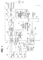
- FIG. 1 is a block diagram giving an overview of an inverter generator according to an embodiment of this invention.
- the inverter generator is designated by reference numeral 10 in FIG. 1 .
- the generator 10 is equipped with an engine (internal combustion engine) 12 and has a rated output of about 3 kW (AC 100 V, 30 A).
- the engine 12 is an air-cooled, spark-ignition engine. Its throttle valve 12a is opened and closed by a throttle motor (actuator) 12b constituted as a stepper motor.
- the engine 12 is started with a recoil starter (not shown).
- a circular stator (not shown) is fastened near the cylinder head of the engine 12.
- the stator is provided with windings that constitute an engine generator unit 14, namely with three-phase (U, V and W) output windings (main windings) 14a and three single-phase windings 14b, 14c and 14d.
- a rotor (not shown) that doubles as the flywheel of the engine 12 is installed in the outside of the stator. Permanent magnets (not shown) are attached in the rotor at positions opposite the aforesaid windings 14a, etc., and with their radially oriented polarities reversed alternately.
- the three-phase alternating current outputted from (generated by) the output windings 14a of the generator unit 14 is passed through U, V and W terminals 14e to a control board (printed board) 16 and inputted to a converter 20 mounted thereon.
- the converter 20 is equipped with bridge-connected three thyristors (SCRs) and three diodes DI.
- SCRs thyristors
- DI diodes
- a ringing choke converter (RCC) power supply (direct current stabilized power supply) 22 is connected to the positive and negative electrode side outputs of the converter 20 and supplies the rectified DC power to the three thyristors as operating power.
- a smoothing capacitor 24 is connected downstream of the RCC power supply 22 to smooth the direct current outputted from the converter 20.
- An inverter 26 is connected downstream of the smoothing capacitor 24.
- the inverter 26 is equipped with a four-FET bridge circuit (FET: field effect transistor (switching element)).
- FET field effect transistor
- the direct current outputted from the converter 20 is converted to alternating current of a predetermined frequency (50 Hz or 60 Hz utility power frequency) by controlling the conducting (ON-OFF) state of the four FETs.
- the output of the inverter 26 is passed through a choke coil 30 composed of an LC filter for harmonic suppression and through a noise filter 32 for noise suppression to be applied to output terminals 34, from which it can be supplied to an electrical load 36 through a connector (not shown) or the like.
- the control board 16 is equipped with a CPU (central processing unit) 40 having a 32-bit architecture.
- the CPU 40 controls the conduction angle of the thyristors of the converter 20 though a thyristor (SCR) driver (drive circuit) 40a, the conducting state of the FETs of the inverter 26 through a gate driver 40b, and the operation of the throttle motor 12b through a motor driver 40c.
- the CPU 40 is equipped with an EEPROM (nonvolatile memory) 40d.
- the output of the first single-phase output winding 14b is sent to the control board 16 through sub-terminals 14b1 and 14b2, where it is inputted to a control power generator 14b3 that generates 5 V operating power for the CPU 40.
- the output from the sub-terminal 14b1 is sent to an NE detection circuit 14b4, where it is converted to a pulse signal and sent to the CPU 40.
- the CPU 40 counts the pulses of the output from the NE detection circuit 14b4 to calculate (detect) the speed NE of the engine 12.
- the output of the second output winding 14c is sent to a full-wave rectifier circuit 14c1, where it is full-wave rectified to produce operating power for the throttle motor 12b, etc.
- the output of the third output winding 14d is sent to an ignition circuit 12c of the engine 12 for use as ignition power for a spark plug 12d.
- the CPU 40 is connected to first and second voltage sensors 40e and 40f.
- the first voltage sensor 40e on downstream of the RCC power supply 22 produces an output or signal proportional to the DC voltage output of the converter 20.
- the second voltage sensor 40f on downstream of the inverter 26 produces an output or signal proportional to the AC voltage output of the inverter 26.
- the outputs of the first and second voltage sensors 40e and 40f are sent to the CPU 40.
- the CPU 40 is further connected to a current sensor 40g.
- the current sensor 40g produces an output or signal proportional to the current outputted from the inverter 26, i.e., the current passing through the electrical load 36 when the load 36 is connected.
- the output of the current sensor 40g is inputted to the CPU 40 and also to an overcurrent limiter 40h constituting a logic circuit (hardware circuit) independent of the CPU 40.
- the overcurrent limiter 40h suspends the output of the gate driver 40b to make the output of the inverter 26 zero temporarily.
- the CPU 40 is inputted with the outputs of the first and second voltage sensors 40e, 40f and current sensor 40g and based thereon, PWM-controls the FETs of the inverter 26, while controlling the operation of the throttle motor 12b, thereby further limiting overcurrent.
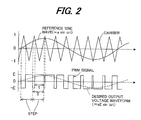
- FIG. 2 is a waveform diagram for explaining the PWM control by the CPU 40.
- the PWM control of the FETs of the inverter 26 will be explained with reference to FIG. 2 .
- a carrier e.g., a 20 kHz carrier wave
- the lower broken-line wave in FIG. 2 indicates the desired output voltage waveform.
- the period T (step) of the PWM signal (PWM waveform), which is actually much shorter than shown, is enlarged in FIG. 2 for ease of understanding. This will be explained later.
- the CPU 40 determines the opening of the throttle valve 12a to establish the desired engine speed calculated based on the AC output determined by the electrical load 36, calculates A phase and B phase output pulses for the throttle stepper motor 12b, and supplies them through the motor driver 40c to the motor 12b from output terminals 40c1, thereby controlling the operation of the motor 12b.
- the control cycle (step) determined by a period of the carrier frequency is also constant or fixed at 50 microseconds, as shown in FIG. 3 .
- This embodiment is therefore configured such that the carrier frequency is varied in accordance with inclination of the reference sine wave, specifically the carrier frequency is decreased as the inclination (slope) of the reference sine wave decreases, as shown in FIG. 4 .
- the carrier frequency is accordingly determined to be 20 kHz in a range of ⁇ 1, and it is determined to be 16 kHz in a range of ⁇ 2.
- the number of steps, i.e., control cycles, more exactly times of switching controls for driving the FETs can be decreased from 400 to 384, as shown in FIG. 4 .
- the switching loss can be decreased by an amount corresponding to the decreased steps, thereby improving power generation efficiency. Further, owing to the decrease in the number of times of switching controls, heating of the FETs can be suppressed.
- carrier frequency is varied in accordance with inclination of the reference sine wave, i.e., it is decreased as decreasing inclination of the reference sine wave. More specifically, when the inclination is small (i.e., gentle), the carrier frequency is decreased to make the control cycle longer (sparser), while, when the inclination is larger (i.e. steeper), the carrier frequency is increased to make the control cycle shorter (denser).
- the carrier frequency is obtained based on the inclination of the reference sine wave in advance and the obtained values are stored as table values together with the control cycles to be retrievable by the number of steps.
- the carrier frequency is prepared as table data to be retrievable by a number of control cycles (i.e., the steps).
- FIG. 6 is a flowchart showing the operation of the CPU 40 using the table values.
- the program begins in S10, in which a value of a counter STEP that counts the number of steps is incremented by 1.
- the program proceeds to S12, in which the control cycle T of the carrier frequency corresponding to the value of the counter STEP is retrieved, to S14, in which the ON time t to the control cycle T is calculated by comparing the reference sine wave with the carrier, and to S16, in which the calculated value is outputted to the gate driver 40b, whereafter the program is terminated.
- the embodiment is configured to have an inverter generator (10) (and a method of controlling the generator (10)) having a generator unit (14) that is driven by an internal combustion engine (12) and generates alternating current, a converter (20) that is connected to the generator unit and converts the alternating current to direct current, an inverter (26) that is connected to the converter and converts the direct current to alternating current with switching elements to supply to an electrical load (36), an inverter driver (CPU 40) that drives the switching elements with a PWM signal generated using a reference sine wave of a desired output voltage waveform and a carrier at every control cycle determined by a carrier frequency and makes the alternating current converted in the inverter to the alternating current of a predetermined frequency, characterized in that : the inverter driver (CPU 40, S10 to S16) varies the carrier frequency in accordance with inclination of the reference sine wave.
- the carrier frequency is varied in accordance with inclination of the reference sine wave, it becomes possible to faithfully generate the output voltage waveform having the reference sine wave to an utmost extent and to suppress the harmonic distortion.
- the inverter driver varies the carrier frequency such that the carrier frequency is decreased as decreasing inclination of the reference sine wave. With this, it becomes possible to decrease the carrier frequency to make the control cycle longer when the inclination is small (i.e., gentle) or to increase the carrier frequency to make the control cycle shorter when the inclination is larger (i.e. steeper), thereby enabling to surely decrease the switching loss and to further suppress the harmonic distortion.
- the carrier frequency is varied in accordance with the inclination of the reference sine wave to decrease the number of the control cycles
- the number of the control cycles need not be decreased.
- the harmonic distortion can be effectively suppressed by decreasing the carrier frequency as decreasing inclination of the reference sine wave.
- FETs are used as the switching elements of the inverter in the foregoing, this is not a limitation and it is possible to use insulated gate bipolar transistors (IGBTs) or the like instead.
- IGBTs insulated gate bipolar transistors
- an inverter generator having an engine generator having a generator unit, a converter that converts generated alternating current to direct current, an inverter that converts the direct current to alternating current with switching elements to supply to an electrical load, an inverter driver that drives the switching elements with a PWM signal generated using a reference sine wave of a desired output voltage waveform and a carrier at every control cycle (step) determined by a carrier frequency and makes the alternating current of a predetermined frequency
- the inverter driver varies the carrier frequency in accordance with inclination (indicated by ⁇ 1, 2 for example) of the reference sine wave, more specifically decreases the carrier frequency as decreasing inclination of the reference sine wave.
Landscapes
- Engineering & Computer Science (AREA)
- Power Engineering (AREA)
- Inverter Devices (AREA)
- Control Of Eletrric Generators (AREA)
Abstract
Description
- This invention relates to an inverter generator, particularly to an inverter generator equipped with a generator unit driven by an internal combustion engine, in which a control cycle of PWM is varied.
- One well-known inverter generator once converts the alternating current outputted by an engine-driven generator unit to direct current and then converts the direct current into alternating current of a predetermined frequency (utility frequency) by driving switching elements with a PWM signal generated using a reference sine wave of the desired output voltage waveform and a carrier. An example of such an inverter generator can be found in Japanese Laid-Open Patent Application No.
H4(1992)-355672 ('672) - In the conventional inverter generator taught by the reference, a carrier frequency is fixed at a constant value as shown in
fig. 6 thereof, and naturally a control cycle determined by a period of the carrier frequency is also fixed at a constant value. - Since the control cycle becomes longer with decreasing carrier frequency, switching loss can be accordingly decreased. On the other hand, voltage ripple grows and harmonic distortion increases. In order to remove the harmonic distortion, a LC filter must have greater performance.
- This invention is therefore directed to overcoming the aforesaid problem by providing an inverter generator that conducts conversion to alternating current of a predetermined frequency based on a PWM signal generated using a reference sine wave of the desired output voltage waveform and a carrier, wherein switching loss is decreased, while increase of harmonic distortion components is suppressed.
- In order to achieve the object, this invention provides in its first aspect an inverter generator having a generator unit that is driven by an internal combustion engine and generates alternating current, a converter that is connected to the generator unit and converts the alternating current to direct current, an inverter that is connected to the converter and converts the direct current to alternating current with switching elements to supply to an electrical load, an inverter driver that drives the switching elements with a PWM signal generated using a reference sine wave of a desired output voltage waveform and a carrier at every control cycle determined by a carrier frequency and makes the alternating current converted in the inverter to the alternating current of a predetermined frequency, wherein the improvement comprises that: the inverter driver varies the carrier frequency in accordance with inclination of the reference sine wave.
- In order to achieve the object, this invention provides in its second aspect a method of controlling an inverter generator having a generator unit that is driven by an internal combustion engine and generates alternating current, a converter that is connected to the generator unit and converts the alternating current to direct current, an inverter that is connected to the converter and converts the direct current to alternating current with switching elements to supply to an electrical load, an inverter driver that drives the switching elements with a PWM signal generated using a reference sine wave of a desired output voltage waveform and a carrier at every control cycle determined by a carrier frequency and makes the alternating current converted in the inverter to the alternating current of a predetermined frequency, comprising the step of: varying the carrier frequency in accordance with inclination of the reference sine wave.
- The above and other objects and advantages of the invention will be more apparent from the following description and drawings in which:
-
FIG. 1 is a block diagram giving an overview of an inverter generator according to an embodiment of this invention; -
FIG. 2 is a waveform diagram for explaining a PWM control by a CPU shown inFIG. 1 ; -
FIG. 3 is a waveform diagram showing a control cycle (step) when a carrier frequency is made constant or fixed in the PWM control by the CPU shown inFIG. 1 ; -
FIG. 4 is a waveform diagram showing a control cycle (step) when the carrier frequency is varied in the PWM control by the CPU shown inFIG. 1 ; -
FIG. 5 is an explanatory view showing table values used in the PWM control by the CPU shown inFIG. 4 ; and -
FIG. 6 is a flowchart showing the operation of the CPU shown inFIG. 4 . - An inverter generator according to an embodiment of this invention will now be explained with reference to the attached drawings.
-
FIG. 1 is a block diagram giving an overview of an inverter generator according to an embodiment of this invention. - The inverter generator is designated by
reference numeral 10 inFIG. 1 . Thegenerator 10 is equipped with an engine (internal combustion engine) 12 and has a rated output of about 3 kW (AC 100 V, 30 A). Theengine 12 is an air-cooled, spark-ignition engine. Its throttle valve 12a is opened and closed by a throttle motor (actuator) 12b constituted as a stepper motor. Theengine 12 is started with a recoil starter (not shown). - A circular stator (not shown) is fastened near the cylinder head of the
engine 12. The stator is provided with windings that constitute anengine generator unit 14, namely with three-phase (U, V and W) output windings (main windings) 14a and three single-phase windings - A rotor (not shown) that doubles as the flywheel of the
engine 12 is installed in the outside of the stator. Permanent magnets (not shown) are attached in the rotor at positions opposite theaforesaid windings 14a, etc., and with their radially oriented polarities reversed alternately. - When the permanent magnets of the rotor surrounding the stator rotate, three-phase (U, V and W phase) alternating current is outputted from (generated by) the three-
phase output windings 14a and single-phase alternating current is outputted from the single-phase output windings - The three-phase alternating current outputted from (generated by) the
output windings 14a of thegenerator unit 14 is passed through U, V andW terminals 14e to a control board (printed board) 16 and inputted to aconverter 20 mounted thereon. Theconverter 20 is equipped with bridge-connected three thyristors (SCRs) and three diodes DI. The three-phase alternating current outputted by thegenerator unit 14 is converted to direct current by controlling the conduction angles of the thyristors. - A ringing choke converter (RCC) power supply (direct current stabilized power supply) 22 is connected to the positive and negative electrode side outputs of the
converter 20 and supplies the rectified DC power to the three thyristors as operating power. Asmoothing capacitor 24 is connected downstream of theRCC power supply 22 to smooth the direct current outputted from theconverter 20. - An
inverter 26 is connected downstream of thesmoothing capacitor 24. Theinverter 26 is equipped with a four-FET bridge circuit (FET: field effect transistor (switching element)). As explained further below, the direct current outputted from theconverter 20 is converted to alternating current of a predetermined frequency (50 Hz or 60 Hz utility power frequency) by controlling the conducting (ON-OFF) state of the four FETs. - The output of the
inverter 26 is passed through achoke coil 30 composed of an LC filter for harmonic suppression and through anoise filter 32 for noise suppression to be applied tooutput terminals 34, from which it can be supplied to anelectrical load 36 through a connector (not shown) or the like. - The
control board 16 is equipped with a CPU (central processing unit) 40 having a 32-bit architecture. TheCPU 40 controls the conduction angle of the thyristors of theconverter 20 though a thyristor (SCR) driver (drive circuit) 40a, the conducting state of the FETs of theinverter 26 through agate driver 40b, and the operation of thethrottle motor 12b through amotor driver 40c. TheCPU 40 is equipped with an EEPROM (nonvolatile memory) 40d. - The output of the first single-phase output winding 14b is sent to the
control board 16 through sub-terminals 14b1 and 14b2, where it is inputted to a control power generator 14b3 that generates 5 V operating power for theCPU 40. The output from the sub-terminal 14b1 is sent to an NE detection circuit 14b4, where it is converted to a pulse signal and sent to theCPU 40. TheCPU 40 counts the pulses of the output from the NE detection circuit 14b4 to calculate (detect) the speed NE of theengine 12. - The output of the second output winding 14c is sent to a full-wave rectifier circuit 14c1, where it is full-wave rectified to produce operating power for the
throttle motor 12b, etc. The output of the third output winding 14d is sent to anignition circuit 12c of theengine 12 for use as ignition power for aspark plug 12d. - The
CPU 40 is connected to first andsecond voltage sensors first voltage sensor 40e on downstream of theRCC power supply 22 produces an output or signal proportional to the DC voltage output of theconverter 20. Thesecond voltage sensor 40f on downstream of theinverter 26 produces an output or signal proportional to the AC voltage output of theinverter 26. The outputs of the first andsecond voltage sensors CPU 40. - The
CPU 40 is further connected to acurrent sensor 40g. Thecurrent sensor 40g produces an output or signal proportional to the current outputted from theinverter 26, i.e., the current passing through theelectrical load 36 when theload 36 is connected. - The output of the
current sensor 40g is inputted to theCPU 40 and also to anovercurrent limiter 40h constituting a logic circuit (hardware circuit) independent of theCPU 40. When the current detected by thecurrent sensor 40g exceeds the tolerance limit, theovercurrent limiter 40h suspends the output of thegate driver 40b to make the output of theinverter 26 zero temporarily. - The
CPU 40 is inputted with the outputs of the first andsecond voltage sensors current sensor 40g and based thereon, PWM-controls the FETs of theinverter 26, while controlling the operation of thethrottle motor 12b, thereby further limiting overcurrent. -
FIG. 2 is a waveform diagram for explaining the PWM control by theCPU 40. - The PWM control of the FETs of the
inverter 26 will be explained with reference toFIG. 2 . Based on a reference sine wave (signal wave) with respect to the predetermined frequency (50 Hz or 60 Hz utility power frequency) of the desired AC output voltage waveform (lower broken-line wave), theCPU 40 uses a comparator (not shown) to compare it with a carrier (e.g., a 20 kHz carrier wave), produces a PWM signal (PWM waveform), namely a variable duty ratio (= ON time t / period T) pulse train, in accordance with PWM (pulse width modulation), and outputs the signal through thegate driver 40b. - The lower broken-line wave in
FIG. 2 indicates the desired output voltage waveform. The period T (step) of the PWM signal (PWM waveform), which is actually much shorter than shown, is enlarged inFIG. 2 for ease of understanding. This will be explained later. - The
CPU 40 determines the opening of the throttle valve 12a to establish the desired engine speed calculated based on the AC output determined by theelectrical load 36, calculates A phase and B phase output pulses for thethrottle stepper motor 12b, and supplies them through themotor driver 40c to themotor 12b from output terminals 40c1, thereby controlling the operation of themotor 12b. - Next, the aforementioned PWM control of the
CPU 40 will be explained again. - When, for instance, the carrier frequency is made constant or fixed at 20 kHz and the frequency of the desired output voltage waveform is 50 Hz, the control cycle (step) determined by a period of the carrier frequency is also constant or fixed at 50 microseconds, as shown in
FIG. 3 . - Since the control cycle becomes longer with decreasing carrier frequency, switching loss of the FETs can be decreased by an amount corresponding to the elongated cycle. On the contrary, voltage ripple grows and harmonic distortion increases. In order to remove the harmonic distortion, the performance of the
choke coil 30 must be enhanced. - This embodiment is therefore configured such that the carrier frequency is varied in accordance with inclination of the reference sine wave, specifically the carrier frequency is decreased as the inclination (slope) of the reference sine wave decreases, as shown in
FIG. 4 . - More specifically, as shown in
FIG. 4 , since, for example, the inclination (slope) indicated by Δ2 of the reference sine wave is smaller (i.e., gentler) than that indicated by Δ1, the carrier frequency is accordingly determined to be 20 kHz in a range of Δ1, and it is determined to be 16 kHz in a range of Δ2. - As a result, the number of steps, i.e., control cycles, more exactly times of switching controls for driving the FETs can be decreased from 400 to 384, as shown in
FIG. 4 . The switching loss can be decreased by an amount corresponding to the decreased steps, thereby improving power generation efficiency. Further, owing to the decrease in the number of times of switching controls, heating of the FETs can be suppressed. - Further, carrier frequency is varied in accordance with inclination of the reference sine wave, i.e., it is decreased as decreasing inclination of the reference sine wave. More specifically, when the inclination is small (i.e., gentle), the carrier frequency is decreased to make the control cycle longer (sparser), while, when the inclination is larger (i.e. steeper), the carrier frequency is increased to make the control cycle shorter (denser).
- Owing to this configuration, it becomes possible to faithfully generate the output voltage waveform of the reference sine wave to an utmost extent. In addition, since the increase of the harmonic distortion can be suppressed, the performance of the
choke coil 30 need not be enhanced. - In the embodiment, as shown in
FIG. 5 , the carrier frequency is obtained based on the inclination of the reference sine wave in advance and the obtained values are stored as table values together with the control cycles to be retrievable by the number of steps. Thus, the carrier frequency is prepared as table data to be retrievable by a number of control cycles (i.e., the steps). -
FIG. 6 is a flowchart showing the operation of theCPU 40 using the table values. - The program begins in S10, in which a value of a counter STEP that counts the number of steps is incremented by 1. The program proceeds to S12, in which the control cycle T of the carrier frequency corresponding to the value of the counter STEP is retrieved, to S14, in which the ON time t to the control cycle T is calculated by comparing the reference sine wave with the carrier, and to S16, in which the calculated value is outputted to the
gate driver 40b, whereafter the program is terminated. - As stated above, the embodiment is configured to have an inverter generator (10) (and a method of controlling the generator (10)) having a generator unit (14) that is driven by an internal combustion engine (12) and generates alternating current, a converter (20) that is connected to the generator unit and converts the alternating current to direct current, an inverter (26) that is connected to the converter and converts the direct current to alternating current with switching elements to supply to an electrical load (36), an inverter driver (CPU 40) that drives the switching elements with a PWM signal generated using a reference sine wave of a desired output voltage waveform and a carrier at every control cycle determined by a carrier frequency and makes the alternating current converted in the inverter to the alternating current of a predetermined frequency, characterized in that: the inverter driver (
CPU 40, S10 to S16) varies the carrier frequency in accordance with inclination of the reference sine wave. - With this, since the carrier frequency is decreased to make the control cycle long, switching loss can be decreased by an amount corresponding to the elongated control cycle, it becomes possible to improve power generation efficiency.
- Further, since the carrier frequency is varied in accordance with inclination of the reference sine wave, it becomes possible to faithfully generate the output voltage waveform having the reference sine wave to an utmost extent and to suppress the harmonic distortion.
- In the generator, the inverter driver varies the carrier frequency such that the carrier frequency is decreased as decreasing inclination of the reference sine wave. With this, it becomes possible to decrease the carrier frequency to make the control cycle longer when the inclination is small (i.e., gentle) or to increase the carrier frequency to make the control cycle shorter when the inclination is larger (i.e. steeper), thereby enabling to surely decrease the switching loss and to further suppress the harmonic distortion.
- Although, in the foregoing, the carrier frequency is varied in accordance with the inclination of the reference sine wave to decrease the number of the control cycles, the number of the control cycles need not be decreased. In that case, while switching loss can not be decreased, the harmonic distortion can be effectively suppressed by decreasing the carrier frequency as decreasing inclination of the reference sine wave.
- Although FETs are used as the switching elements of the inverter in the foregoing, this is not a limitation and it is possible to use insulated gate bipolar transistors (IGBTs) or the like instead.
- In an inverter generator having an engine generator having a generator unit, a converter that converts generated alternating current to direct current, an inverter that converts the direct current to alternating current with switching elements to supply to an electrical load, an inverter driver that drives the switching elements with a PWM signal generated using a reference sine wave of a desired output voltage waveform and a carrier at every control cycle (step) determined by a carrier frequency and makes the alternating current of a predetermined frequency, the inverter driver varies the carrier frequency in accordance with inclination (indicated by
Δ 1, 2 for example) of the reference sine wave, more specifically decreases the carrier frequency as decreasing inclination of the reference sine wave.
Claims (6)
- An inverter generator (10) having a generator unit (14) that is driven by an internal combustion engine (12) and generates alternating current, a converter (20) that is connected to the generator unit and converts the alternating current to direct current, an inverter (26) that is connected to the converter and converts the direct current to alternating current with switching elements to supply to an electrical load (36), an inverter driver (40) that drives the switching elements with a PWM signal generated using a reference sine wave of a desired output voltage waveform and a carrier at every control cycle determined by a carrier frequency and makes the alternating current converted in the inverter to the alternating current of a predetermined frequency,
characterized in that:
the inverter driver (40, S10 to S 16) varies the carrier frequency in accordance with inclination of the reference sine wave. - The inverter generator according to claim 1, wherein the inverter driver (40) varies the carrier frequency such that the carrier frequency is decreased as decreasing inclination of the reference sine wave.
- The inverter generator according to claim 1 or 2, wherein the carrier frequency is prepared as table data to be retrievable by a number of the control cycles and the inverter driver (40) calculates the carrier frequency to be varied by retrieving the table data (S10 to S16).
- A method of controlling an inverter generator (10) having a generator unit (14) that is driven by an internal combustion engine (12) and generates alternating current, a converter (20) that is connected to the generator unit and converts the alternating current to direct current, an inverter (26) that is connected to the converter and converts the direct current to alternating current with switching elements to supply to an electrical load (36), an inverter driver (40) that drives the switching elements with a PWM signal generated using a reference sine wave of a desired output voltage waveform and a carrier at every control cycle determined by a carrier frequency and makes the alternating current converted in the inverter to the alternating current of a predetermined frequency,
characterized by the step of:
varying the carrier frequency in accordance with inclination of the reference sine wave (S10 to S16). - The method according to claim 4, wherein the carrier frequency is decreased as decreasing inclination of the reference sine wave.
- The method according to claim 4 or 5, wherein the carrier frequency is prepared as table data to be retrievable by a number of the control cycles and the step of varying the carrier frequency calculates the carrier frequency to be varied by retrieving the table data (S10 to S16).
Applications Claiming Priority (1)
| Application Number | Priority Date | Filing Date | Title |
|---|---|---|---|
| JP2008191781A JP2010035260A (en) | 2008-07-25 | 2008-07-25 | Inverter generator |
Publications (2)
| Publication Number | Publication Date |
|---|---|
| EP2148429A1 true EP2148429A1 (en) | 2010-01-27 |
| EP2148429B1 EP2148429B1 (en) | 2010-06-30 |
Family
ID=40970925
Family Applications (1)
| Application Number | Title | Priority Date | Filing Date |
|---|---|---|---|
| EP09165695A Not-in-force EP2148429B1 (en) | 2008-07-25 | 2009-07-16 | Inverter generator |
Country Status (8)
| Country | Link |
|---|---|
| US (1) | US20100020572A1 (en) |
| EP (1) | EP2148429B1 (en) |
| JP (1) | JP2010035260A (en) |
| CN (1) | CN101635558B (en) |
| AU (1) | AU2009202714B2 (en) |
| CA (1) | CA2672820A1 (en) |
| DE (1) | DE602009000052D1 (en) |
| RU (1) | RU2406216C1 (en) |
Cited By (1)
| Publication number | Priority date | Publication date | Assignee | Title |
|---|---|---|---|---|
| DE102020208381A1 (en) | 2020-07-03 | 2022-01-05 | Siemens Aktiengesellschaft | Power converter and method for operating a power converter |
Families Citing this family (19)
| Publication number | Priority date | Publication date | Assignee | Title |
|---|---|---|---|---|
| EP2315929A4 (en) | 2008-07-03 | 2013-06-26 | Fuel Saving Technologies Llc | Fuel conservation systems and methods |
| US8639430B2 (en) | 2008-07-03 | 2014-01-28 | Fuel Saving Technologies, Llc | Energy conservation systems and methods |
| JP5375715B2 (en) * | 2010-03-31 | 2013-12-25 | 株式会社豊田自動織機 | Neutral point boost DC-three-phase converter |
| JP4924761B1 (en) * | 2011-02-17 | 2012-04-25 | セイコーエプソン株式会社 | Capacitive load drive circuit and fluid ejection device |
| CN102312737B (en) * | 2011-03-15 | 2013-06-19 | 隆鑫通用动力股份有限公司 | Frequency doubling inversing method and device for internal combustion engine driven generator |
| JP5553288B2 (en) * | 2011-03-15 | 2014-07-16 | 株式会社豊田自動織機 | Inverter device for rotating electrical machine and driving method for rotating electrical machine |
| JP2012244691A (en) * | 2011-05-17 | 2012-12-10 | Honda Motor Co Ltd | Control device for inverter generator |
| RU2515474C2 (en) * | 2011-05-17 | 2014-05-10 | Хонда Мотор Ко., Лтд. | Inverter generator |
| RU2540416C2 (en) * | 2011-05-17 | 2015-02-10 | Хонда Мотор Ко., Лтд. | Inverter generator |
| EP2769071B1 (en) * | 2011-10-19 | 2018-08-15 | Fuel Saving Technologies, Inc. | Energy conservation systems and methods |
| RU2558722C1 (en) * | 2014-04-16 | 2015-08-10 | Федеральное государственное бюджетное образовательное учреждение высшего профессионального образования "Новосибирский государственный технический университет" | Independent three-phase inverter control method |
| DE102014219052A1 (en) * | 2014-09-22 | 2016-03-24 | Wobben Properties Gmbh | Method for generating an alternating electrical current |
| KR101789134B1 (en) * | 2015-09-25 | 2017-10-31 | 전남대학교산학협력단 | Variable frequency modulation method for inverter |
| JP6613425B2 (en) * | 2015-10-28 | 2019-12-04 | 京都電機器株式会社 | DC-AC inverter device |
| CN106787921B (en) * | 2017-01-23 | 2019-07-19 | 深圳市金芯微电子有限公司 | An inverter control method with adjustable input and output parameters |
| JP2019004653A (en) * | 2017-06-19 | 2019-01-10 | 株式会社リコー | PWM control apparatus, switching power supply apparatus, image forming apparatus, PWM control method, and program |
| JP7178163B2 (en) * | 2018-12-14 | 2022-11-25 | ニチコン株式会社 | power converter |
| JP7167786B2 (en) * | 2019-03-15 | 2022-11-09 | 株式会社Ihi | power generation system |
| CN112803866B (en) * | 2021-02-26 | 2023-02-28 | 依必安派特风机(上海)有限公司 | Motor sine wave drive control method and system and motor |
Citations (5)
| Publication number | Priority date | Publication date | Assignee | Title |
|---|---|---|---|---|
| JPH04236171A (en) * | 1991-01-21 | 1992-08-25 | Meidensha Corp | Method for suppressing output voltage waveform distortion of inverter |
| JPH05103475A (en) * | 1991-10-04 | 1993-04-23 | Mitsubishi Electric Corp | Inverter sine wave approximate PWM signal generator |
| JP2002153096A (en) * | 2000-11-10 | 2002-05-24 | Denso Corp | Inverter control device for AC motor generator for vehicle |
| JP2004312922A (en) * | 2003-04-09 | 2004-11-04 | Toyota Motor Corp | Power converter controller |
| JP2007020320A (en) * | 2005-07-08 | 2007-01-25 | Yaskawa Electric Corp | PWM inverter device and control method thereof |
Family Cites Families (9)
| Publication number | Priority date | Publication date | Assignee | Title |
|---|---|---|---|---|
| US4520437A (en) * | 1983-07-14 | 1985-05-28 | At&T Bell Laboratories | Power conversion circuit for synthesizing a sinewave with programmed amplitude control |
| JP3113294B2 (en) * | 1991-01-24 | 2000-11-27 | 本田技研工業株式会社 | Portable generator |
| JP2688660B2 (en) * | 1991-05-30 | 1997-12-10 | 本田技研工業株式会社 | Inverter device |
| JP2003158880A (en) * | 2001-11-20 | 2003-05-30 | Toshiba Corp | Inverter device |
| RU2230976C1 (en) * | 2002-10-17 | 2004-06-20 | Федеральное Государственное унитарное предприятие "Государственное научно-производственное предприятие "Сплав" | High pressure bottle |
| JP2004282826A (en) * | 2003-03-13 | 2004-10-07 | Honda Motor Co Ltd | Engine driven generator |
| RU2282301C2 (en) * | 2004-10-11 | 2006-08-20 | Государственное образовательное учреждение высшего профессионального образования Самарский государственный технический университет | Energy plant with asynchronous starter-generator |
| JP4929863B2 (en) * | 2005-08-30 | 2012-05-09 | 富士電機株式会社 | Power converter |
| JP2007326449A (en) * | 2006-06-07 | 2007-12-20 | Mazda Motor Corp | Hybrid car |
-
2008
- 2008-07-25 JP JP2008191781A patent/JP2010035260A/en active Pending
-
2009
- 2009-07-03 AU AU2009202714A patent/AU2009202714B2/en not_active Ceased
- 2009-07-16 EP EP09165695A patent/EP2148429B1/en not_active Not-in-force
- 2009-07-16 DE DE602009000052T patent/DE602009000052D1/en active Active
- 2009-07-17 CN CN2009101403780A patent/CN101635558B/en not_active Expired - Fee Related
- 2009-07-20 US US12/505,792 patent/US20100020572A1/en not_active Abandoned
- 2009-07-23 CA CA2672820A patent/CA2672820A1/en not_active Abandoned
- 2009-07-23 RU RU2009128333/07A patent/RU2406216C1/en not_active IP Right Cessation
Patent Citations (5)
| Publication number | Priority date | Publication date | Assignee | Title |
|---|---|---|---|---|
| JPH04236171A (en) * | 1991-01-21 | 1992-08-25 | Meidensha Corp | Method for suppressing output voltage waveform distortion of inverter |
| JPH05103475A (en) * | 1991-10-04 | 1993-04-23 | Mitsubishi Electric Corp | Inverter sine wave approximate PWM signal generator |
| JP2002153096A (en) * | 2000-11-10 | 2002-05-24 | Denso Corp | Inverter control device for AC motor generator for vehicle |
| JP2004312922A (en) * | 2003-04-09 | 2004-11-04 | Toyota Motor Corp | Power converter controller |
| JP2007020320A (en) * | 2005-07-08 | 2007-01-25 | Yaskawa Electric Corp | PWM inverter device and control method thereof |
Cited By (1)
| Publication number | Priority date | Publication date | Assignee | Title |
|---|---|---|---|---|
| DE102020208381A1 (en) | 2020-07-03 | 2022-01-05 | Siemens Aktiengesellschaft | Power converter and method for operating a power converter |
Also Published As
| Publication number | Publication date |
|---|---|
| US20100020572A1 (en) | 2010-01-28 |
| CA2672820A1 (en) | 2010-01-25 |
| JP2010035260A (en) | 2010-02-12 |
| DE602009000052D1 (en) | 2010-08-12 |
| CN101635558B (en) | 2012-03-28 |
| CN101635558A (en) | 2010-01-27 |
| AU2009202714A1 (en) | 2010-02-11 |
| AU2009202714B2 (en) | 2010-09-16 |
| RU2406216C1 (en) | 2010-12-10 |
| EP2148429B1 (en) | 2010-06-30 |
Similar Documents
| Publication | Publication Date | Title |
|---|---|---|
| EP2148429B1 (en) | Inverter generator | |
| CA2672827C (en) | Inverter generator | |
| CA2672824C (en) | Inverter generator | |
| CA2672832C (en) | Speed controlled inverter generator | |
| EP2148427B1 (en) | Inverter generator | |
| CN101635556B (en) | Inverter generator | |
| JP5130143B2 (en) | Inverter generator |
Legal Events
| Date | Code | Title | Description |
|---|---|---|---|
| PUAI | Public reference made under article 153(3) epc to a published international application that has entered the european phase |
Free format text: ORIGINAL CODE: 0009012 |
|
| 17P | Request for examination filed |
Effective date: 20090716 |
|
| AK | Designated contracting states |
Kind code of ref document: A1 Designated state(s): AT BE BG CH CY CZ DE DK EE ES FI FR GB GR HR HU IE IS IT LI LT LU LV MC MK MT NL NO PL PT RO SE SI SK SM TR |
|
| AX | Request for extension of the european patent |
Extension state: AL BA RS |
|
| GRAP | Despatch of communication of intention to grant a patent |
Free format text: ORIGINAL CODE: EPIDOSNIGR1 |
|
| GRAS | Grant fee paid |
Free format text: ORIGINAL CODE: EPIDOSNIGR3 |
|
| GRAA | (expected) grant |
Free format text: ORIGINAL CODE: 0009210 |
|
| AK | Designated contracting states |
Kind code of ref document: B1 Designated state(s): DE FR GB IT |
|
| REG | Reference to a national code |
Ref country code: GB Ref legal event code: FG4D |
|
| REF | Corresponds to: |
Ref document number: 602009000052 Country of ref document: DE Date of ref document: 20100812 Kind code of ref document: P |
|
| PLBE | No opposition filed within time limit |
Free format text: ORIGINAL CODE: 0009261 |
|
| STAA | Information on the status of an ep patent application or granted ep patent |
Free format text: STATUS: NO OPPOSITION FILED WITHIN TIME LIMIT |
|
| 26N | No opposition filed |
Effective date: 20110331 |
|
| REG | Reference to a national code |
Ref country code: DE Ref legal event code: R097 Ref document number: 602009000052 Country of ref document: DE Effective date: 20110330 |
|
| REG | Reference to a national code |
Ref country code: FR Ref legal event code: PLFP Year of fee payment: 8 |
|
| PGFP | Annual fee paid to national office [announced via postgrant information from national office to epo] |
Ref country code: FR Payment date: 20160613 Year of fee payment: 8 |
|
| PGFP | Annual fee paid to national office [announced via postgrant information from national office to epo] |
Ref country code: GB Payment date: 20160713 Year of fee payment: 8 Ref country code: DE Payment date: 20160712 Year of fee payment: 8 Ref country code: IT Payment date: 20160720 Year of fee payment: 8 |
|
| REG | Reference to a national code |
Ref country code: DE Ref legal event code: R119 Ref document number: 602009000052 Country of ref document: DE |
|
| GBPC | Gb: european patent ceased through non-payment of renewal fee |
Effective date: 20170716 |
|
| REG | Reference to a national code |
Ref country code: FR Ref legal event code: ST Effective date: 20180330 |
|
| PG25 | Lapsed in a contracting state [announced via postgrant information from national office to epo] |
Ref country code: GB Free format text: LAPSE BECAUSE OF NON-PAYMENT OF DUE FEES Effective date: 20170716 Ref country code: DE Free format text: LAPSE BECAUSE OF NON-PAYMENT OF DUE FEES Effective date: 20180201 |
|
| PG25 | Lapsed in a contracting state [announced via postgrant information from national office to epo] |
Ref country code: FR Free format text: LAPSE BECAUSE OF NON-PAYMENT OF DUE FEES Effective date: 20170731 |
|
| PG25 | Lapsed in a contracting state [announced via postgrant information from national office to epo] |
Ref country code: IT Free format text: LAPSE BECAUSE OF NON-PAYMENT OF DUE FEES Effective date: 20170716 |