EP2147860A2 - Heat exchanger assembly for an aircraft control - Google Patents
Heat exchanger assembly for an aircraft control Download PDFInfo
- Publication number
- EP2147860A2 EP2147860A2 EP09251024A EP09251024A EP2147860A2 EP 2147860 A2 EP2147860 A2 EP 2147860A2 EP 09251024 A EP09251024 A EP 09251024A EP 09251024 A EP09251024 A EP 09251024A EP 2147860 A2 EP2147860 A2 EP 2147860A2
- Authority
- EP
- European Patent Office
- Prior art keywords
- fluid
- thermoelectric device
- assembly
- aircraft
- temperature
- Prior art date
- Legal status (The legal status is an assumption and is not a legal conclusion. Google has not performed a legal analysis and makes no representation as to the accuracy of the status listed.)
- Granted
Links
- 239000012530 fluid Substances 0.000 claims abstract description 128
- 238000004891 communication Methods 0.000 claims abstract description 7
- 239000000446 fuel Substances 0.000 claims description 5
- 238000001816 cooling Methods 0.000 claims description 3
- 238000000034 method Methods 0.000 claims description 3
- 238000007789 sealing Methods 0.000 claims 1
- LYCAIKOWRPUZTN-UHFFFAOYSA-N Ethylene glycol Chemical compound OCCO LYCAIKOWRPUZTN-UHFFFAOYSA-N 0.000 description 3
- 239000000758 substrate Substances 0.000 description 3
- 238000012986 modification Methods 0.000 description 2
- 230000004048 modification Effects 0.000 description 2
- 229910052782 aluminium Inorganic materials 0.000 description 1
- XAGFODPZIPBFFR-UHFFFAOYSA-N aluminium Chemical compound [Al] XAGFODPZIPBFFR-UHFFFAOYSA-N 0.000 description 1
- 239000012080 ambient air Substances 0.000 description 1
- 230000002528 anti-freeze Effects 0.000 description 1
- 230000005540 biological transmission Effects 0.000 description 1
- 230000006870 function Effects 0.000 description 1
- 229910052751 metal Inorganic materials 0.000 description 1
- 239000002184 metal Substances 0.000 description 1
- 238000005086 pumping Methods 0.000 description 1
Images

Classifications
-
- B—PERFORMING OPERATIONS; TRANSPORTING
- B64—AIRCRAFT; AVIATION; COSMONAUTICS
- B64D—EQUIPMENT FOR FITTING IN OR TO AIRCRAFT; FLIGHT SUITS; PARACHUTES; ARRANGEMENT OR MOUNTING OF POWER PLANTS OR PROPULSION TRANSMISSIONS IN AIRCRAFT
- B64D13/00—Arrangements or adaptations of air-treatment apparatus for aircraft crew or passengers, or freight space
-
- B—PERFORMING OPERATIONS; TRANSPORTING
- B64—AIRCRAFT; AVIATION; COSMONAUTICS
- B64D—EQUIPMENT FOR FITTING IN OR TO AIRCRAFT; FLIGHT SUITS; PARACHUTES; ARRANGEMENT OR MOUNTING OF POWER PLANTS OR PROPULSION TRANSMISSIONS IN AIRCRAFT
- B64D33/00—Arrangement in aircraft of power plant parts or auxiliaries not otherwise provided for
- B64D33/08—Arrangement in aircraft of power plant parts or auxiliaries not otherwise provided for of power plant cooling systems
-
- B—PERFORMING OPERATIONS; TRANSPORTING
- B64—AIRCRAFT; AVIATION; COSMONAUTICS
- B64D—EQUIPMENT FOR FITTING IN OR TO AIRCRAFT; FLIGHT SUITS; PARACHUTES; ARRANGEMENT OR MOUNTING OF POWER PLANTS OR PROPULSION TRANSMISSIONS IN AIRCRAFT
- B64D37/00—Arrangements in connection with fuel supply for power plant
- B64D37/34—Conditioning fuel, e.g. heating
-
- F—MECHANICAL ENGINEERING; LIGHTING; HEATING; WEAPONS; BLASTING
- F24—HEATING; RANGES; VENTILATING
- F24F—AIR-CONDITIONING; AIR-HUMIDIFICATION; VENTILATION; USE OF AIR CURRENTS FOR SCREENING
- F24F5/00—Air-conditioning systems or apparatus not covered by F24F1/00 or F24F3/00, e.g. using solar heat or combined with household units such as an oven or water heater
- F24F5/0042—Air-conditioning systems or apparatus not covered by F24F1/00 or F24F3/00, e.g. using solar heat or combined with household units such as an oven or water heater characterised by the application of thermo-electric units or the Peltier effect
-
- H—ELECTRICITY
- H10—SEMICONDUCTOR DEVICES; ELECTRIC SOLID-STATE DEVICES NOT OTHERWISE PROVIDED FOR
- H10N—ELECTRIC SOLID-STATE DEVICES NOT OTHERWISE PROVIDED FOR
- H10N10/00—Thermoelectric devices comprising a junction of dissimilar materials, i.e. devices exhibiting Seebeck or Peltier effects
- H10N10/10—Thermoelectric devices comprising a junction of dissimilar materials, i.e. devices exhibiting Seebeck or Peltier effects operating with only the Peltier or Seebeck effects
- H10N10/13—Thermoelectric devices comprising a junction of dissimilar materials, i.e. devices exhibiting Seebeck or Peltier effects operating with only the Peltier or Seebeck effects characterised by the heat-exchanging means at the junction
-
- B—PERFORMING OPERATIONS; TRANSPORTING
- B64—AIRCRAFT; AVIATION; COSMONAUTICS
- B64D—EQUIPMENT FOR FITTING IN OR TO AIRCRAFT; FLIGHT SUITS; PARACHUTES; ARRANGEMENT OR MOUNTING OF POWER PLANTS OR PROPULSION TRANSMISSIONS IN AIRCRAFT
- B64D13/00—Arrangements or adaptations of air-treatment apparatus for aircraft crew or passengers, or freight space
- B64D13/06—Arrangements or adaptations of air-treatment apparatus for aircraft crew or passengers, or freight space the air being conditioned
- B64D2013/0603—Environmental Control Systems
- B64D2013/0614—Environmental Control Systems with subsystems for cooling avionics
-
- B—PERFORMING OPERATIONS; TRANSPORTING
- B64—AIRCRAFT; AVIATION; COSMONAUTICS
- B64D—EQUIPMENT FOR FITTING IN OR TO AIRCRAFT; FLIGHT SUITS; PARACHUTES; ARRANGEMENT OR MOUNTING OF POWER PLANTS OR PROPULSION TRANSMISSIONS IN AIRCRAFT
- B64D13/00—Arrangements or adaptations of air-treatment apparatus for aircraft crew or passengers, or freight space
- B64D13/06—Arrangements or adaptations of air-treatment apparatus for aircraft crew or passengers, or freight space the air being conditioned
- B64D2013/0603—Environmental Control Systems
- B64D2013/0659—Environmental Control Systems comprising provisions for cooling fuel systems
-
- B—PERFORMING OPERATIONS; TRANSPORTING
- B64—AIRCRAFT; AVIATION; COSMONAUTICS
- B64D—EQUIPMENT FOR FITTING IN OR TO AIRCRAFT; FLIGHT SUITS; PARACHUTES; ARRANGEMENT OR MOUNTING OF POWER PLANTS OR PROPULSION TRANSMISSIONS IN AIRCRAFT
- B64D13/00—Arrangements or adaptations of air-treatment apparatus for aircraft crew or passengers, or freight space
- B64D13/06—Arrangements or adaptations of air-treatment apparatus for aircraft crew or passengers, or freight space the air being conditioned
- B64D2013/0603—Environmental Control Systems
- B64D2013/0674—Environmental Control Systems comprising liquid subsystems
Definitions
- This invention relates to a heat exchanger for an aircraft control.
- An aircraft has a number of electronic controls used to control an operation of the aircraft.
- One such control manages the function of the aircraft engines and is commonly known as a Full Authority Digital Engine Control or FADEC.
- the FADEC is generally installed in an environment of the aircraft susceptible to both very high temperatures and very low temperatures.
- the FADEC may be installed in the engine bay where large amounts of heat are generated during flight conditions. In these conditions, the FADEC requires a substantial amount of cooling to limit its operating temperature.
- the engine bay may be extremely cold when ambient air temperature is low. At these conditions, the FADEC requires very little, if any, cooling.
- the FADEC like many aircraft controls, is composed of electronic components that require moderate and uniform temperatures for optimal operation.
- the large temperature swings experienced by the FADEC are not conducive to the best performance of these temperature sensitive components.
- a heat exchanger assembly includes an aircraft control.
- the aircraft control is in thermal communication with a first fluid.
- a first thermoelectric device is configured to transfer heat between the first fluid and a second fluid against a temperature gradient of the first fluid and the second fluid.
- a temperature sensor is provided for sensing a temperature of the first fluid.
- a temperature control is also configured to control the first thermoelectric device based on an input from the temperature sensor.
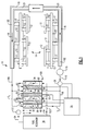
- FIG 1 there is shown heat exchanger assembly 10 for aircraft control 14.
- Figure 1 is a schematic and shows the general operation of heat exchanger assembly 10.
- aircraft control 14 such as a FADEC, for example, is composed of printed circuit boards 12.
- Printed circuit boards 12 are mounted to frame 19 in a tiered fashion.
- Printed circuit boards 12 are mounted to heat sinks 15 and conduction posts 17, which are all mounted to frame 19. This arrangement permits heat to be transferred between printed circuit boards 12 and frame 19.
- Frame 19 has first fluid 18 to act as a heat exchanger for printed circuit boards 12 through heat sinks 15 and heat conduction posts 17.
- first fluid 18 may be any of a variety of fluids, including aircraft engine fuel, ethylene glycol or any antifreeze.
- Frame 19 has fluid channel 21, an internal conduit that allows the circulation of first fluid 18 via pump 115 to thermoelectric assembly 108 and back to frame 19.
- First fluid 18 is contained in a closed fluid loop, here closed first loop 102.
- thermoelectric assembly 108 At thermoelectric assembly 108, first fluid 18 exchanges heat with second fluid 34.
- Second fluid 34 is contained in another closed loop, second closed loop 103, which includes, by way of example, aircraft fuel reservoir 36, pump 117, and thermoelectric assembly 108.
- Pump 117 pumps second fluid 34, here aircraft engine fuel, through thermoelectric assembly 108 back to fuel reservoir 36.
- thermoelectric assembly 108 The exchange of heat between first fluid 18 and second fluid 34 occurs through thermoelectric assembly 108.
- second fluid 34 is at a higher temperature than first fluid 18.
- Thermoelectric assembly 108 is provided to thereby allow first fluid 18 to transfer heat to second fluid 34 against the temperature gradient of the two fluids.
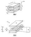
- Thermoelectric assembly 108 has first thermoelectric device 22, second thermoelectric device 70 and third thermoelectric device 82. As shown in Figure 5 , each thermoelectric device, such as first thermoelectric device 22, has thermoelectric elements 111 disposed on substrate 24. Each thermoelectric element 111 is configured to pump heat as known against a temperature gradient. Thermoelectric elements 111 are collectively oriented so that heat may be pumped either in the direction of arrow R or the direction of arrow S, both directions perpendicular to the mounting substrate 24. The direction can be controlled by controlling the direction of electric current flow for thermoelectric elements 111. Electric current flow in one direction will pump heat in the direction of arrow R while current flow in the opposite direction will pump heat in the direction of arrow S. Adjusting the level of electric current will adjust the rate of heat pumping.
- First thermally conductive plate 94 and second thermally conductive plate 98 sandwich and encase substrate 24 so as to prevent fluid from damaging thermoelectric elements 111. Because first thermally conductive plate 94 and second thermally conductive plate 98 are both made of metal, they further provide a highly thermally conductive surface for the transmission of heat in the direction of arrow R or in the direction of arrow S. Hence, heat may be transferred between two fluids, such as first fluid 18 and second fluid 34, against the temperature gradient between the two fluids by controlling the electric current through thermoelectric elements 111.
- thermoelectric assembly 108 Excess heat from printed circuit boards 12 is passed to heat sinks 15 though heat conduction posts 17 and to frame 19 and ultimately to first fluid 18.
- First fluid 18 is circulated by pump 115 to thermoelectric assembly 108 along first flow path 106.
- first fluid 18 is passed in proximity to second fluid 34, which is circulated by pump 117 in the opposite direction as first fluid 18.
- Heat is transferred between first fluid 18 and second fluid 34 via first thermoelectric device 22, second thermoelectric device 70 and third thermoelectric device 82. These devices allow heat to be transferred even if the temperature of first fluid 18 is lower than the temperature of second fluid 34 at thermoelectric assembly 108.
- first fluid 18 After exiting thermoelectric assembly 108, first fluid 18 has a temperature that helps maintain printed circuit boards 12 at their desired operating temperature.
- thermoelectric device 22 With reference to first thermoelectric device 22 shown in Figure 1-3 , the heat exchange between first fluid 18 and second fluid 34 occurs by passing first fluid 18 in the direction of arrow A through first plurality of flow conduits 46 along first thermoelectric device 22. As shown, second fluid 34 is channeled through second plurality of flow conduits 50 in the direction of arrow B, an opposite direction from the direction of flow of first fluid 18. Second plurality of flow conduits 50 is disposed on the other side of first thermoelectric device 22. First fluid 18 has temperature T 1 while second fluid 34 has temperature T 2 . If temperature of T 2 is greater than temperature T 1 , thermoelectric device 22 pumps heat from first fluid 18 to second fluid 34, even though second fluid 34 has a higher temperature.
- thermoelectric assembly 108 may be transferred from first fluid 18 to second fluid 34 so as to cool first fluid 18 coming from thermoelectric assembly 108 to temperature T 3 , which is then returned to frame 19 along second flow path 110 so as to provide flow for moderating the temperature of printed circuit boards 12.
- thermoelectric assembly 108 has three thermoelectric devices, here first thermoelectric device 22, second thermoelectric device 70 and third thermoelectric device 82.
- First thermoelectric device has first side 38 and second side 42 while second thermoelectric device 70 has third side 74 and fourth side 78 and third thermoelectric device 82 has fifth side 86 and sixth side 90.
- On first side 38 is first plurality of flow conduits while between second side 42 and third side 74 is disposed second plurality of flow conduits 50.
- fourth side 78 and fifth side 86 is disposed third plurality of flow conduits 54.
- Fourth plurality of flow conduits 58 is on sixth side 90.
- This layering and structuring of flow conduits and thermoelectric devices can be seen in perspective view in Figure 2 .
- flow conduits are stacked on thermoelectric devices. More or fewer layers of thermoelectric devices and flow conduits may be employed.
- first plurality of flow conducts 46, first thermoelectric device 22 and second plurality of flow conduits 50 is shown in Figure 3 .
- the temperature gradient between first fluid 18 and second fluid 34 is in the direction of arrow Q.
- first fluid 18 is cooler than second fluid 34.
- Thermoelectric device 22 allows heat to flow in the opposite direction of arrow Q, here the direction of arrow R so as to transfer heat from first fluid 18 to second fluid 34.
- each thermoelectric device here first thermoelectric device 22, second thermoelectric device 70 and third thermoelectric device 82 are controlled by temperature control 30, which is in communication with temperature sensor 26.
- Temperature sensor 26 measures the temperature of first fluid 18 in closed loop 102 and provides an input for temperature control 30 to adjust current flow to the thermoelectric devices so as to maintain first fluid 18 at a temperature that will maintain printed circuit boards 12 within operational parameters.
- first fluid 18 may, in fact, be at a lower temperature than second fluid 34.
- temperature control 30 may reverse current to first thermoelectric device 22, second thermoelectric device 70 and third thermoelectric device 82 so that they transfer heat in the opposite direction, from second fluid 34 to first fluid 18. Temperature of first fluid 18 can be moderated in this fashion.
- first fluid 18 is pumped in the direction of arrow A while second fluid 34 is pumped in the opposite direction, in the direction of arrow B.
- Figure 4 shows an alternative arrangement of flow conduits to create a cross-flow between first fluid 18 and second fluid 34.
- first fluid 18 is pumped in the direction of arrow C, say through first plurality of flow conduits 46, while second fluid 34 is pumped through second plurality of flow conduits 50 in the direction of arrow D, transverse to the direction of arrow C.
Landscapes
- Engineering & Computer Science (AREA)
- Aviation & Aerospace Engineering (AREA)
- Chemical & Material Sciences (AREA)
- Combustion & Propulsion (AREA)
- Mechanical Engineering (AREA)
- Sustainable Development (AREA)
- Life Sciences & Earth Sciences (AREA)
- General Engineering & Computer Science (AREA)
- Health & Medical Sciences (AREA)
- General Health & Medical Sciences (AREA)
- Pulmonology (AREA)
- Cooling Or The Like Of Electrical Apparatus (AREA)
- Control Of Temperature (AREA)
Abstract
Description
- This invention relates to a heat exchanger for an aircraft control. An aircraft has a number of electronic controls used to control an operation of the aircraft. One such control manages the function of the aircraft engines and is commonly known as a Full Authority Digital Engine Control or FADEC. The FADEC is generally installed in an environment of the aircraft susceptible to both very high temperatures and very low temperatures. For example, the FADEC may be installed in the engine bay where large amounts of heat are generated during flight conditions. In these conditions, the FADEC requires a substantial amount of cooling to limit its operating temperature. When the aircraft is not in flight, however, the engine bay may be extremely cold when ambient air temperature is low. At these conditions, the FADEC requires very little, if any, cooling.
- The FADEC, like many aircraft controls, is composed of electronic components that require moderate and uniform temperatures for optimal operation. The large temperature swings experienced by the FADEC are not conducive to the best performance of these temperature sensitive components. While there are electronic components that are capable of performing at the extreme temperature conditions of the aircraft, these components are generally very expensive and have relatively low performance (memory, process, or speed) compared to most modem electronics.
- A need therefore exists for an assembly and technique that maintains the electronics of an aircraft control within their designed operating temperatures.
- A heat exchanger assembly includes an aircraft control. The aircraft control is in thermal communication with a first fluid. A first thermoelectric device is configured to transfer heat between the first fluid and a second fluid against a temperature gradient of the first fluid and the second fluid. A temperature sensor is provided for sensing a temperature of the first fluid. A temperature control is also configured to control the first thermoelectric device based on an input from the temperature sensor.
- The various features and advantages of this invention will become apparent to those skilled in the art from the following detailed description of the currently preferred embodiment. The drawings that accompany the detailed description can be briefly described as follows:
-
Figure 1 illustrates a schematic view of a heat exchanger assembly for an aircraft control, showing first thermoelectric device, second thermoelectric device and third thermoelectric device. -
Figure 2 illustrates a perspective view of the thermoelectric devices ofFigure 1 , including a plurality of flow conduits. -
Figure 3 illustrates a close up view of the thermoelectric device ofFigure 2 , highlighting the flow conduits in relation to a thermoelectric device. -
Figure 4 illustrates an alternative arrangement of flow conduits ofFigure 3 . -
Figure 5 illustrates an exploded view of the thermoelectric device ofFigure 3 . - In
Figure 1 there is shownheat exchanger assembly 10 foraircraft control 14.Figure 1 is a schematic and shows the general operation ofheat exchanger assembly 10. As shown,aircraft control 14, such as a FADEC, for example, is composed ofprinted circuit boards 12. Printedcircuit boards 12 are mounted toframe 19 in a tiered fashion. Printedcircuit boards 12 are mounted toheat sinks 15 andconduction posts 17, which are all mounted toframe 19. This arrangement permits heat to be transferred between printedcircuit boards 12 andframe 19. -
Frame 19 hasfirst fluid 18 to act as a heat exchanger for printedcircuit boards 12 throughheat sinks 15 andheat conduction posts 17. In this regard,first fluid 18 may be any of a variety of fluids, including aircraft engine fuel, ethylene glycol or any antifreeze.Frame 19 hasfluid channel 21, an internal conduit that allows the circulation offirst fluid 18 viapump 115 tothermoelectric assembly 108 and back toframe 19.First fluid 18 is contained in a closed fluid loop, here closedfirst loop 102. - At
thermoelectric assembly 108,first fluid 18 exchanges heat withsecond fluid 34.Second fluid 34 is contained in another closed loop, second closedloop 103, which includes, by way of example,aircraft fuel reservoir 36,pump 117, andthermoelectric assembly 108.Pump 117 pumpssecond fluid 34, here aircraft engine fuel, throughthermoelectric assembly 108 back tofuel reservoir 36. - The exchange of heat between
first fluid 18 andsecond fluid 34 occurs throughthermoelectric assembly 108. Normally,second fluid 34 is at a higher temperature thanfirst fluid 18. Hence, transferring heat fromfirst fluid 18, which is at a lower temperature thansecond fluid 34, is against the temperature gradient between the two fluids and generally would not occur.Thermoelectric assembly 108 is provided to thereby allowfirst fluid 18 to transfer heat tosecond fluid 34 against the temperature gradient of the two fluids. -
Thermoelectric assembly 108 has firstthermoelectric device 22, secondthermoelectric device 70 and thirdthermoelectric device 82. As shown inFigure 5 , each thermoelectric device, such as firstthermoelectric device 22, hasthermoelectric elements 111 disposed onsubstrate 24. Eachthermoelectric element 111 is configured to pump heat as known against a temperature gradient.Thermoelectric elements 111 are collectively oriented so that heat may be pumped either in the direction of arrow R or the direction of arrow S, both directions perpendicular to themounting substrate 24. The direction can be controlled by controlling the direction of electric current flow forthermoelectric elements 111. Electric current flow in one direction will pump heat in the direction of arrow R while current flow in the opposite direction will pump heat in the direction of arrow S. Adjusting the level of electric current will adjust the rate of heat pumping. - First thermally
conductive plate 94 and second thermallyconductive plate 98, here made of aluminum, sandwich andencase substrate 24 so as to prevent fluid from damagingthermoelectric elements 111. Because first thermallyconductive plate 94 and second thermallyconductive plate 98 are both made of metal, they further provide a highly thermally conductive surface for the transmission of heat in the direction of arrow R or in the direction of arrow S. Hence, heat may be transferred between two fluids, such asfirst fluid 18 andsecond fluid 34, against the temperature gradient between the two fluids by controlling the electric current throughthermoelectric elements 111. - The operation of
heat exchanger assembly 10 will now be explained with reference toFigure 1 . Excess heat from printedcircuit boards 12 is passed toheat sinks 15 thoughheat conduction posts 17 and to frame 19 and ultimately tofirst fluid 18.First fluid 18 is circulated bypump 115 tothermoelectric assembly 108 alongfirst flow path 106. There,first fluid 18 is passed in proximity tosecond fluid 34, which is circulated bypump 117 in the opposite direction asfirst fluid 18. Heat is transferred betweenfirst fluid 18 andsecond fluid 34 via firstthermoelectric device 22, secondthermoelectric device 70 and thirdthermoelectric device 82. These devices allow heat to be transferred even if the temperature offirst fluid 18 is lower than the temperature ofsecond fluid 34 atthermoelectric assembly 108. After exitingthermoelectric assembly 108,first fluid 18 has a temperature that helps maintain printedcircuit boards 12 at their desired operating temperature. - With reference to first
thermoelectric device 22 shown inFigure 1-3 , the heat exchange betweenfirst fluid 18 andsecond fluid 34 occurs by passingfirst fluid 18 in the direction of arrow A through first plurality offlow conduits 46 along firstthermoelectric device 22. As shown,second fluid 34 is channeled through second plurality offlow conduits 50 in the direction of arrow B, an opposite direction from the direction of flow offirst fluid 18. Second plurality offlow conduits 50 is disposed on the other side of firstthermoelectric device 22.First fluid 18 has temperature T1 whilesecond fluid 34 has temperature T2. If temperature of T2 is greater than temperature T1,thermoelectric device 22 pumps heat fromfirst fluid 18 tosecond fluid 34, even thoughsecond fluid 34 has a higher temperature. In this way, heat may be transferred fromfirst fluid 18 tosecond fluid 34 so as to coolfirst fluid 18 coming fromthermoelectric assembly 108 to temperature T3, which is then returned toframe 19 alongsecond flow path 110 so as to provide flow for moderating the temperature of printedcircuit boards 12. - As shown in
Figure 1 , multiple layers of thermoelectric devices are used to improve the rate of heat exchange between first fluid 18 andsecond fluid 34. By way of example,thermoelectric assembly 108 has three thermoelectric devices, here firstthermoelectric device 22, secondthermoelectric device 70 and thirdthermoelectric device 82. First thermoelectric device has first side 38 and second side 42 while secondthermoelectric device 70 hasthird side 74 andfourth side 78 and thirdthermoelectric device 82 hasfifth side 86 andsixth side 90. On first side 38 is first plurality of flow conduits while between second side 42 andthird side 74 is disposed second plurality offlow conduits 50. Betweenfourth side 78 andfifth side 86 is disposed third plurality offlow conduits 54. Fourth plurality offlow conduits 58 is onsixth side 90. This layering and structuring of flow conduits and thermoelectric devices can be seen in perspective view inFigure 2 . There, as shown, flow conduits are stacked on thermoelectric devices. More or fewer layers of thermoelectric devices and flow conduits may be employed. - A close up view of first plurality of flow conducts 46, first
thermoelectric device 22 and second plurality offlow conduits 50 is shown inFigure 3 . There, it is shown that the temperature gradient between first fluid 18 andsecond fluid 34 is in the direction of arrow Q. In other words,first fluid 18 is cooler thansecond fluid 34.Thermoelectric device 22 allows heat to flow in the opposite direction of arrow Q, here the direction of arrow R so as to transfer heat fromfirst fluid 18 tosecond fluid 34. - As shown
Figure 1 , each thermoelectric device, here firstthermoelectric device 22, secondthermoelectric device 70 and thirdthermoelectric device 82 are controlled bytemperature control 30, which is in communication withtemperature sensor 26.Temperature sensor 26 measures the temperature offirst fluid 18 inclosed loop 102 and provides an input fortemperature control 30 to adjust current flow to the thermoelectric devices so as to maintainfirst fluid 18 at a temperature that will maintain printedcircuit boards 12 within operational parameters. - There may be times when the temperature of
first fluid 18 is too low, such as when the aircraft is inactive and ambient temperature is cold. In such an instance,first fluid 18 may, in fact, be at a lower temperature thansecond fluid 34. Then,temperature control 30 may reverse current to firstthermoelectric device 22, secondthermoelectric device 70 and thirdthermoelectric device 82 so that they transfer heat in the opposite direction, fromsecond fluid 34 tofirst fluid 18. Temperature offirst fluid 18 can be moderated in this fashion. - In
Figure 1 and3 , to facilitate the exchange of heat,first fluid 18 is pumped in the direction of arrow A whilesecond fluid 34 is pumped in the opposite direction, in the direction of arrow B.Figure 4 shows an alternative arrangement of flow conduits to create a cross-flow between first fluid 18 andsecond fluid 34. There,first fluid 18 is pumped in the direction of arrow C, say through first plurality offlow conduits 46, whilesecond fluid 34 is pumped through second plurality offlow conduits 50 in the direction of arrow D, transverse to the direction of arrow C. - The aforementioned description is exemplary rather that limiting. Many modifications and variations of the present invention are possible in light of the above teachings. The preferred embodiments of this invention have been disclosed. However, one of ordinary skill in the art would recognize that certain modifications would come within the scope of this invention. Hence, within the scope of the appended claims, the invention may be practiced otherwise than as specifically described. For this reason the following claims should be studied to determine the true scope and content of this invention.
Claims (15)
- A heat exchanger assembly (10) for an aircraft control (14), comprising:an aircraft control (14) for controlling an operation of an aircraft;said aircraft control being in thermal communication with a first fluid (8);a first thermoelectric device (22) configured to transfer heat between said first fluid and a second fluid (34) against a temperature gradient of said first fluid and said second fluid;a temperature sensor (26) for sensing a temperature of said first fluid; anda temperature control (30) configured to control said first thermoelectric device based on an input from said temperature sensor.
- The assembly of Claim 1 wherein said second fluid (34) is an aircraft engine fuel.
- The assembly of Claim 1 or 2 wherein said first thermoelectric device has a first side (38) and a second side (42), said first fluid being in thermal communication with said first side and said second fluid being in thermal communication with said second side.
- The assembly of Claim 3 including a first plurality of flow conduits and a second plurality of flow conduits, said first plurality of flow conduits being arranged to guide said first fluid across said first side (38) of said first thermoelectric device and said second plurality of flow conduits being arranged to guide said second fluid across said second side (42) of said first thermoelectric device.
- The assembly of Claim 3 or 4 including a second thermoelectric device, said second thermoelectric device (70) spaced from said first thermoelectric device and having a third side (74) and fourth side (78), said third side facing said second side (42) of said first thermoelectric device, and said second fluid being disposed between said second side and said third side.
- The assembly of Claim 5 including a third thermoelectric device (82) having a fifth side (86) and a sixth side (98) , said fifth side facing said fourth (78) side of said second thermoelectric device wherein said second thermoelectric device is sandwiched between said first thermoelectric device and said third thermoelectric device.
- The assembly of Claim 6 wherein said first fluid is on said first side, said second fluid disposed on said second side between said second side and said third side, said first fluid is also disposed between said fourth side and said fifth side, and said second fluid is also disposed on said sixth side.
- The assembly of any preceding Claim wherein said first thermoelectric device (22) is configured to cool said first fluid when said second fluid has a higher temperature than said first fluid.
- The assembly of any preceding Claim including a first thermally conductive plate (94) and a second thermally conductive plate (98), said first thermoelectric device being sandwiched by said first thermally conductive plate and said second thermally conductive plate, said first thermally conductive plate and said second thermally conductive plate sealing said first thermoelectric device against fluid.
- The assembly of any preceding Claim wherein said first fluid is disposed in a closed loop.
- A heat exchanger assembly (10) for an aircraft control (14), comprising:an aircraft control (14) for an aircraft;said aircraft control being in thermal communication with a first fluid (18) configured to cool said control;a first thermoelectric device (22) configured to transfer heat from said first fluid to a second fluid (34) having a higher temperature than said first fluid, said first thermoelectric device having a first side (38) and a second side (42);a second thermoelectric device (70), said second thermoelectric device being spaced from said first thermoelectric device and having a third side (74) and fourth side (78), said third side facing said second side of said first thermoelectric device; andwherein said first fluid is on said first side, said second fluid is between said second side and said third side, and said first fluid is also on said fourth side.
- The assembly of Claim 11 including a third thermoelectric device (82) having a fifth side (86) and a sixth side (90), said fifth side facing said fourth side (78) of said second thermoelectric device (70) wherein said second thermoelectric device is sandwiched between said first thermoelectric device and said third thermoelectric device wherein said first fluid is also disposed between said fourth side and said fifth side, and said second fluid is also disposed on said sixth side.
- The assembly of Claim 11 or 12 including a first plurality of flow conduits and a second plurality of flow conduits, said first plurality of flow conduits being arranged to guide said first fluid across said first side of said first thermoelectric device and said second plurality of flow conduits being arranged to guide said second fluid across said second side of said first thermoelectric device.
- The assembly of Claim 4 or 13 wherein said first fluid is configured to flow along said first side in a first direction and said second fluid is configured to flow along said second side in a second direction, said first direction being different from said second direction; preferably wherein said first direction is generally opposite said second direction, alternatively wherein said first direction is transverse to said second direction.
- A method of controlling a temperature for an aircraft control, comprising the steps of:disposing a first fluid (18) proximate a control (14) for an aircraft, the first fluid being configured to absorb heat from the control for the aircraft;providing a first flow path to a thermoelectric device (108);disposing a second fluid (34) proximate the thermoelectric device, the second fluid being configured to absorb heat from the first fluid through the thermoelectric device;providing a second flow path for the first fluid from the thermoelectric device to the control; andwherein the thermoelectric device is configured to transfer heat from the first fluid to the second fluid when the first fluid has a lower temperature than the second fluid thereby cooling the first fluid.
Applications Claiming Priority (1)
| Application Number | Priority Date | Filing Date | Title |
|---|---|---|---|
| US12/176,522 US20100011781A1 (en) | 2008-07-21 | 2008-07-21 | Heat exchanger assembly for an aircraft control |
Publications (3)
| Publication Number | Publication Date |
|---|---|
| EP2147860A2 true EP2147860A2 (en) | 2010-01-27 |
| EP2147860A3 EP2147860A3 (en) | 2013-03-06 |
| EP2147860B1 EP2147860B1 (en) | 2015-09-09 |
Family
ID=41137338
Family Applications (1)
| Application Number | Title | Priority Date | Filing Date |
|---|---|---|---|
| EP09251024.7A Ceased EP2147860B1 (en) | 2008-07-21 | 2009-03-31 | Heat exchanger assembly for an aircraft control |
Country Status (2)
| Country | Link |
|---|---|
| US (1) | US20100011781A1 (en) |
| EP (1) | EP2147860B1 (en) |
Cited By (5)
| Publication number | Priority date | Publication date | Assignee | Title |
|---|---|---|---|---|
| WO2011071602A3 (en) * | 2009-12-07 | 2011-08-18 | The Boeing Company | Thermoelectric generator on an aircraft bleed system |
| RU2435709C1 (en) * | 2010-05-31 | 2011-12-10 | Закрытое акционерное общество "Гражданские самолеты Сухого" | Method of fuel temperature regulation in airplane fuel system |
| EP3121120A1 (en) * | 2015-07-24 | 2017-01-25 | Hamilton Sundstrand Corporation | Aircraft heat exchange system including a thermoelectric device |
| EP3181456A1 (en) * | 2015-12-17 | 2017-06-21 | Hamilton Sundstrand Corporation | Aircraft heat exchange system including a thermoelectric device |
| US9914545B2 (en) | 2015-07-24 | 2018-03-13 | Hamilton Sundstrand Corporation | Aircraft heat exchange system including a thermoelectric device |
Families Citing this family (15)
| Publication number | Priority date | Publication date | Assignee | Title |
|---|---|---|---|---|
| DE102006046114B4 (en) * | 2006-09-28 | 2012-02-02 | Airbus Operations Gmbh | Cooling arrangement for cooling a heat body for an aircraft |
| US9395109B2 (en) | 2010-05-26 | 2016-07-19 | Agilent Technologies, Inc. | Efficient chiller for a supercritical fluid chromatography pump |
| US9318682B2 (en) | 2012-01-25 | 2016-04-19 | Alphabet Energy, Inc | Modular thermoelectric units for heat recovery systems and methods thereof |
| US20130213449A1 (en) * | 2012-02-20 | 2013-08-22 | Marlow Industries, Inc. | Thermoelectric plate and frame exchanger |
| US9257627B2 (en) | 2012-07-23 | 2016-02-09 | Alphabet Energy, Inc. | Method and structure for thermoelectric unicouple assembly |
| US9065017B2 (en) | 2013-09-01 | 2015-06-23 | Alphabet Energy, Inc. | Thermoelectric devices having reduced thermal stress and contact resistance, and methods of forming and using the same |
| US10472986B2 (en) * | 2014-01-24 | 2019-11-12 | United Technologies Corporation | Systems for thermoelectric cooling for jet aircraft propulsion systems |
| US10371415B2 (en) * | 2014-02-19 | 2019-08-06 | The Boeing Company | Electronics operation for temperature controlled systems |
| EP2942508B1 (en) * | 2014-05-08 | 2022-08-24 | Rolls-Royce North American Technologies, Inc. | Enhanced heat sink availability on gas turbine engines through the use of solid state heat pumps |
| US20170005250A1 (en) * | 2015-06-30 | 2017-01-05 | The Boeing Company | Powering aircraft sensors using thermal capacitors |
| US10801408B2 (en) * | 2016-02-03 | 2020-10-13 | Rolls-Royce North American Technologies Inc. | Gas turbine engine with thermoelectric system |
| US10612468B2 (en) * | 2016-02-18 | 2020-04-07 | Rolls-Royce North American Technologies Inc. | Gas turbine engine with thermoelectric intercooler |
| US10654576B2 (en) * | 2016-02-26 | 2020-05-19 | Rolls-Royce North American Technologies Inc. | Gas turbine engine with thermoelectric cooling air heat exchanger |
| EP4165352A4 (en) | 2020-06-15 | 2024-08-07 | DTP Thermoelectrics LLC | Thermoelectric enhanced hybrid heat pump systems |
| US12392286B2 (en) | 2022-10-17 | 2025-08-19 | General Electric Company | Pump systems having dual-function heat exchangers and related methods |
Citations (3)
| Publication number | Priority date | Publication date | Assignee | Title |
|---|---|---|---|---|
| US20030005706A1 (en) | 2001-02-09 | 2003-01-09 | Bell Lon E | Compact, high-efficiency thermoelectric systems |
| DE10332770A1 (en) | 2003-07-17 | 2005-02-24 | Jürgen Dr.-Ing. Schulz-Harder | Cooling device for dissipating heat loss from an electrical or electronic component or assembly |
| WO2008061712A1 (en) | 2006-11-20 | 2008-05-29 | Airbus Deutschland Gmbh | Multistage cooling of electronic components of an aircraft |
Family Cites Families (13)
| Publication number | Priority date | Publication date | Assignee | Title |
|---|---|---|---|---|
| US5203162A (en) * | 1990-09-12 | 1993-04-20 | United Technologies Corporation | Compressor bleed manifold for a gas turbine engine |
| US5181313A (en) * | 1990-12-19 | 1993-01-26 | United Technologies Automotive | Method of making a variable power resistor |
| US5367890A (en) * | 1993-07-13 | 1994-11-29 | Marlow Industries, Inc. | Integrated thermoelectric system with full/half wave rectifier control |
| US5584183A (en) * | 1994-02-18 | 1996-12-17 | Solid State Cooling Systems | Thermoelectric heat exchanger |
| GB2333352B (en) * | 1997-08-22 | 2000-12-27 | Icee Ltd | A heat exchange unit |
| US6532154B2 (en) * | 2001-01-09 | 2003-03-11 | Rockwell Automation Technologies, Inc. | Stack assembly housing |
| US6557354B1 (en) * | 2002-04-04 | 2003-05-06 | International Business Machines Corporation | Thermoelectric-enhanced heat exchanger |
| JP2004071764A (en) * | 2002-08-05 | 2004-03-04 | Mitsubishi Heavy Ind Ltd | Electronic device cooler |
| US6816378B1 (en) * | 2003-04-28 | 2004-11-09 | Hewlett-Packard Development Company, L.P. | Stack up assembly |
| US7260926B2 (en) * | 2004-01-20 | 2007-08-28 | United Technologies Corporation | Thermal management system for an aircraft |
| US7231769B2 (en) * | 2004-01-29 | 2007-06-19 | United Technologies Corporation | Gas turbine cooling system |
| US7779811B1 (en) * | 2006-09-13 | 2010-08-24 | General Electric Company | Thermoelectrically cooled components for distributed electronics control system for gas turbine engines |
| ATE432873T1 (en) * | 2006-09-25 | 2009-06-15 | Saab Ab | AVIONICS COOLING |
-
2008
- 2008-07-21 US US12/176,522 patent/US20100011781A1/en not_active Abandoned
-
2009
- 2009-03-31 EP EP09251024.7A patent/EP2147860B1/en not_active Ceased
Patent Citations (3)
| Publication number | Priority date | Publication date | Assignee | Title |
|---|---|---|---|---|
| US20030005706A1 (en) | 2001-02-09 | 2003-01-09 | Bell Lon E | Compact, high-efficiency thermoelectric systems |
| DE10332770A1 (en) | 2003-07-17 | 2005-02-24 | Jürgen Dr.-Ing. Schulz-Harder | Cooling device for dissipating heat loss from an electrical or electronic component or assembly |
| WO2008061712A1 (en) | 2006-11-20 | 2008-05-29 | Airbus Deutschland Gmbh | Multistage cooling of electronic components of an aircraft |
Cited By (7)
| Publication number | Priority date | Publication date | Assignee | Title |
|---|---|---|---|---|
| WO2011071602A3 (en) * | 2009-12-07 | 2011-08-18 | The Boeing Company | Thermoelectric generator on an aircraft bleed system |
| US8484983B2 (en) | 2009-12-07 | 2013-07-16 | The Boeing Company | Thermoelectric generator on an aircraft bleed system |
| RU2435709C1 (en) * | 2010-05-31 | 2011-12-10 | Закрытое акционерное общество "Гражданские самолеты Сухого" | Method of fuel temperature regulation in airplane fuel system |
| EP3121120A1 (en) * | 2015-07-24 | 2017-01-25 | Hamilton Sundstrand Corporation | Aircraft heat exchange system including a thermoelectric device |
| US9914545B2 (en) | 2015-07-24 | 2018-03-13 | Hamilton Sundstrand Corporation | Aircraft heat exchange system including a thermoelectric device |
| US10225950B2 (en) | 2015-07-24 | 2019-03-05 | Hamilton Sundstrand Corporation | Aircraft heat exchange system including a thermoelectric device |
| EP3181456A1 (en) * | 2015-12-17 | 2017-06-21 | Hamilton Sundstrand Corporation | Aircraft heat exchange system including a thermoelectric device |
Also Published As
| Publication number | Publication date |
|---|---|
| EP2147860A3 (en) | 2013-03-06 |
| US20100011781A1 (en) | 2010-01-21 |
| EP2147860B1 (en) | 2015-09-09 |
Similar Documents
| Publication | Publication Date | Title |
|---|---|---|
| EP2147860B1 (en) | Heat exchanger assembly for an aircraft control | |
| JP5351898B2 (en) | System and method for thermal control of an electronic display | |
| EP3316669B1 (en) | Integrated card rail and cooling module for embedded computing systems | |
| US8929080B2 (en) | Immersion-cooling of selected electronic component(s) mounted to printed circuit board | |
| US6411512B1 (en) | High performance cold plate | |
| US8953317B2 (en) | Wicking vapor-condenser facilitating immersion-cooling of electronic component(s) | |
| US9043035B2 (en) | Dynamically limiting energy consumed by cooling apparatus | |
| US8516792B2 (en) | System for managing the heat fluxes of an aircraft | |
| CN113573542A (en) | Compute node tray cooling | |
| US20120180477A1 (en) | Thermal management systems and methods | |
| US20110308783A1 (en) | Fluid-powered heat exchanger apparatus for cooling electronic equipment | |
| US10892665B2 (en) | Variable speed constant frequency (VSCF) generator system | |
| US20170081040A1 (en) | Heat exchanger and cooling system for generator electronics cooling | |
| CA2406331A1 (en) | Thermal management system | |
| WO2007114913A2 (en) | Multi device cooling | |
| US11549765B2 (en) | Coolant circuit for a drive device and method for operating a coolant circuit | |
| US12123652B2 (en) | Liquid cooling system | |
| US20140198452A1 (en) | Disassemblable electronic assembly with leak-inhibiting coolant capillaries | |
| US20190128271A1 (en) | Pump with integrated bypass mechanism | |
| EP3284929A1 (en) | Heat exchanger arrangement and method | |
| CN106767045A (en) | Plate-type heat exchanger with bypass and method for manufacturing such a heat exchanger | |
| EP2584879B1 (en) | High temperature environment capable motor controller | |
| US10550928B2 (en) | Thermal management of a system for transmission active warm up and internal electronics cooling | |
| EP3121120B1 (en) | Aircraft heat exchange system including a thermoelectric device | |
| US11886258B2 (en) | Hybrid heat sink for electronics cooling |
Legal Events
| Date | Code | Title | Description |
|---|---|---|---|
| PUAI | Public reference made under article 153(3) epc to a published international application that has entered the european phase |
Free format text: ORIGINAL CODE: 0009012 |
|
| AK | Designated contracting states |
Kind code of ref document: A2 Designated state(s): AT BE BG CH CY CZ DE DK EE ES FI FR GB GR HR HU IE IS IT LI LT LU LV MC MK MT NL NO PL PT RO SE SI SK TR |
|
| AX | Request for extension of the european patent |
Extension state: AL BA RS |
|
| PUAL | Search report despatched |
Free format text: ORIGINAL CODE: 0009013 |
|
| AK | Designated contracting states |
Kind code of ref document: A3 Designated state(s): AT BE BG CH CY CZ DE DK EE ES FI FR GB GR HR HU IE IS IT LI LT LU LV MC MK MT NL NO PL PT RO SE SI SK TR |
|
| AX | Request for extension of the european patent |
Extension state: AL BA RS |
|
| RIC1 | Information provided on ipc code assigned before grant |
Ipc: B64D 13/00 20060101AFI20130131BHEP Ipc: B64D 33/08 20060101ALI20130131BHEP Ipc: H01L 35/30 20060101ALI20130131BHEP Ipc: B64D 37/34 20060101ALI20130131BHEP Ipc: F24F 5/00 20060101ALI20130131BHEP |
|
| 17P | Request for examination filed |
Effective date: 20130906 |
|
| RBV | Designated contracting states (corrected) |
Designated state(s): AT BE BG CH CY CZ DE DK EE ES FI FR GB GR HR HU IE IS IT LI LT LU LV MC MK MT NL NO PL PT RO SE SI SK TR |
|
| AKX | Designation fees paid |
Designated state(s): DE GB |
|
| 17Q | First examination report despatched |
Effective date: 20131018 |
|
| REG | Reference to a national code |
Ref country code: DE Ref legal event code: R079 Ref document number: 602009033495 Country of ref document: DE Free format text: PREVIOUS MAIN CLASS: B64D0013000000 Ipc: B64D0013060000 |
|
| GRAP | Despatch of communication of intention to grant a patent |
Free format text: ORIGINAL CODE: EPIDOSNIGR1 |
|
| RIC1 | Information provided on ipc code assigned before grant |
Ipc: H01L 35/30 20060101ALI20150306BHEP Ipc: B64D 37/34 20060101ALI20150306BHEP Ipc: F24F 5/00 20060101ALI20150306BHEP Ipc: B64D 13/06 20060101AFI20150306BHEP Ipc: B64D 33/08 20060101ALI20150306BHEP |
|
| INTG | Intention to grant announced |
Effective date: 20150331 |
|
| GRAS | Grant fee paid |
Free format text: ORIGINAL CODE: EPIDOSNIGR3 |
|
| GRAA | (expected) grant |
Free format text: ORIGINAL CODE: 0009210 |
|
| AK | Designated contracting states |
Kind code of ref document: B1 Designated state(s): DE GB |
|
| REG | Reference to a national code |
Ref country code: GB Ref legal event code: FG4D |
|
| REG | Reference to a national code |
Ref country code: DE Ref legal event code: R096 Ref document number: 602009033495 Country of ref document: DE |
|
| REG | Reference to a national code |
Ref country code: DE Ref legal event code: R097 Ref document number: 602009033495 Country of ref document: DE |
|
| PLBE | No opposition filed within time limit |
Free format text: ORIGINAL CODE: 0009261 |
|
| STAA | Information on the status of an ep patent application or granted ep patent |
Free format text: STATUS: NO OPPOSITION FILED WITHIN TIME LIMIT |
|
| 26N | No opposition filed |
Effective date: 20160610 |
|
| PGFP | Annual fee paid to national office [announced via postgrant information from national office to epo] |
Ref country code: GB Payment date: 20200221 Year of fee payment: 12 Ref country code: DE Payment date: 20200218 Year of fee payment: 12 |
|
| REG | Reference to a national code |
Ref country code: DE Ref legal event code: R082 Ref document number: 602009033495 Country of ref document: DE |
|
| REG | Reference to a national code |
Ref country code: DE Ref legal event code: R119 Ref document number: 602009033495 Country of ref document: DE |
|
| GBPC | Gb: european patent ceased through non-payment of renewal fee |
Effective date: 20210331 |
|
| PG25 | Lapsed in a contracting state [announced via postgrant information from national office to epo] |
Ref country code: GB Free format text: LAPSE BECAUSE OF NON-PAYMENT OF DUE FEES Effective date: 20210331 Ref country code: DE Free format text: LAPSE BECAUSE OF NON-PAYMENT OF DUE FEES Effective date: 20211001 |