EP2147818A1 - A bucket suitable for a child vehicle seat as well as such a child vehicle seat - Google Patents
A bucket suitable for a child vehicle seat as well as such a child vehicle seat Download PDFInfo
- Publication number
- EP2147818A1 EP2147818A1 EP09075242A EP09075242A EP2147818A1 EP 2147818 A1 EP2147818 A1 EP 2147818A1 EP 09075242 A EP09075242 A EP 09075242A EP 09075242 A EP09075242 A EP 09075242A EP 2147818 A1 EP2147818 A1 EP 2147818A1
- Authority
- EP
- European Patent Office
- Prior art keywords
- seat
- bucket
- stiffening ribs
- stiffening
- child vehicle
- Prior art date
- Legal status (The legal status is an assumption and is not a legal conclusion. Google has not performed a legal analysis and makes no representation as to the accuracy of the status listed.)
- Granted
Links
Images


Classifications
-
- B—PERFORMING OPERATIONS; TRANSPORTING
- B60—VEHICLES IN GENERAL
- B60N—SEATS SPECIALLY ADAPTED FOR VEHICLES; VEHICLE PASSENGER ACCOMMODATION NOT OTHERWISE PROVIDED FOR
- B60N2/00—Seats specially adapted for vehicles; Arrangement or mounting of seats in vehicles
- B60N2/24—Seats specially adapted for vehicles; Arrangement or mounting of seats in vehicles for particular purposes or particular vehicles
- B60N2/26—Seats specially adapted for vehicles; Arrangement or mounting of seats in vehicles for particular purposes or particular vehicles for children
- B60N2/28—Seats readily mountable on, and dismountable from, existing seats or other parts of the vehicle
-
- B—PERFORMING OPERATIONS; TRANSPORTING
- B60—VEHICLES IN GENERAL
- B60N—SEATS SPECIALLY ADAPTED FOR VEHICLES; VEHICLE PASSENGER ACCOMMODATION NOT OTHERWISE PROVIDED FOR
- B60N2/00—Seats specially adapted for vehicles; Arrangement or mounting of seats in vehicles
- B60N2/68—Seat frames
- B60N2/686—Panel like structures
Definitions
- the invention relates to a bucket suitable for a child vehicle seat, which bucket is provided with a seat comprising a seat portion and a backrest that joins said seat portion, said seat being provided with at least one stiffening rib on a side of the backrest remote from the seat portion.
- the invention further relates to a child vehicle seat provided with such a bucket.
- Such a bucket is usually provided with a belt system comprising shoulder belts and lap belts, by means of which a child can be secured in the bucket.
- the bucket itself is attached to a vehicle via separate means, such as a safety belt or a so-called isofix system.
- the seat is provided, on a side of the backrest remote from the seat portion, with two stiffening ribs extending parallel to each other. Said stiffening ribs also extend under the seat portion. The stiffening ribs give the seat additional stiffness, so that forces exerted on the child and on the bucket, for example in case of a collision, can be absorbed in an effective manner.
- the known bucket is formed as an integrated part, so that a solid connection between the seat and the stiffening ribs is obtained.
- a drawback of the use of such a bucket formed as one unit is the fact that it limits the freedom of design, since requirements made of the seat as well as requirements made of the stiffening ribs must be taken into account at the same time.
- the object of the invention is to provide a bucket in which this drawback is avoided.
- the seat and the stiffening rib as separate parts makes it possible to realise an ergonomically optimum seat and at the same time maintain a certain degree of freedom of design.
- the seat may be made of any suitable material. Since the forces are absorbed by the stiffening ribs, the seat itself need not be sturdy and may have a relatively small wall thickness. The smaller the wall thickness, the shorter the time required for forming the seat, for example by injection moulding.
- the stiffening ribs may be made of a material suitable for absorbing forces and may have a relatively large wall thickness. Since the seat and the stiffening ribs are produced as separate parts, the relatively large difference in wall thickness does not lead to problems, for example upon injection moulding. Such problems would actually occur if the bucket were made in one piece.
- stiffening ribs and the seat as separate parts is that it is possible to use different stiffening ribs for one and the same seat, depending on the specific requirements made of a bucket.
- a bucket provided with a particular stiffening rib and test it in crash tests, for example. If said tests should demonstrate that the stiffening ribs need to be stiffened or that less stiffness will suffice, there is no need to adapt the mould or other tool for forming the seat, but it will suffice to merely adapt the mould or other tool for forming the stiffening rib.
- the stiffness of the bucket can thus be adapted more easily, for example if views or requirements imposed by the authorities should change in the course of time.
- One embodiment of the bucket according to the invention is characterised in that the stiffening rib is made of another material than the seat.
- Forming the seat of polypropylene and forming the stiffening ribs of polypropylene filled with glass fibres, for example, makes it possible to optimise the material selection in dependence on the requirements made of the seat and the stiffening ribs, for example.
- Another embodiment of the bucket according to the invention is characterised in that the stiffening rib is detachably connected to the seat.
- the stiffening rib is connected to the seat by means of a screwed connection, for example. Assembly will thus be relatively easy.
- Yet another embodiment of the bucket according to the invention is characterised in that the bucket is provided with two stiffening ribs extending substantially parallel to each other, which stiffening ribs are interconnected by means of at least one spacer.
- the spacers and the stiffening ribs provide the seat with the proper stiffness.
- the spacers make it possible to use two relatively thin stiffening ribs, so that a maximum stiffness can be realised while using a minimum amount of material.
- Yet another embodiment of the bucket according to the invention is characterised in that said spacer comprises a rod extending transversely to the stiffening ribs.
- Such a rod is relatively simple. Moreover, such a rod is also suitable for use as a point of engagement, for example for a belt system or for connecting/disconnecting a bucket to/from a chassis.
- Yet another embodiment of the bucket according to the invention is characterised in that the backrest is provided with an opening, whilst a shoulder belt guide extends between the stiffening ribs, which shoulder belt guide is disposed opposite the opening provided in the backrest.
- Another embodiment of the bucket according to the invention is characterised in that the stiffening rib is L-shaped, extending over the backrest and the seat portion.
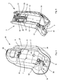
- FIGS 1-3 show a bucket 1 according to the invention, which comprises a seat 2, two stiffening ribs 3, two rods 4 interconnecting the stiffening ribs 3 and a shoulder belt guide 5 extending between the stiffening ribs 3.
- the seat 2 comprises a seat portion 6 and a backrest 7 joining said seat portion 6. Lateral supports 8 are disposed or on either side of the seat portion 6 and the backrest 7. An opening 9 is provided in the backrest 7, which opening is located opposite the shoulder belt guide 4 in the assembled condition of the bucket.
- the seat 2 is made of a relatively thin material, such as polypropylene, ABS, HDPE, ASA and PA, for example.
- the seat 2 can be produced in a relatively short time, for example by injection-moulding. Furthermore, relatively little material is required, so that the seat 2 is relatively light in weight.
- the thickness is 1.2 - 3 mm, for example, preferably 1.7 - 2.0 mm.
- Relatively thin stiffening strips 10 are provided for stiffening the seat 2.
- the seat 2 is further provided with positioning strips 11, against which the stiffening ribs 3 can be positioned in a relatively simple manner for being aligned with the seat 2.
- Each stiffening rib 3 comprises a wall 12 extending substantially along the entire circumference of the stiffening rib 3, with connecting walls 13 extending between opposite walls 12.
- the stiffening rib 3 is L-shaped and, in the assembled condition of the bucket 1, extends over a side of the backrest 7 remote from the seat portion 6, or, in other words, the rear side of the backrest 7, and over an underside of the seat portion 6.
- the number of connecting walls 13, the angles between said connecting walls 13 and the walls 12, the wall thicknesses of the walls 12 and the connecting walls 13 etc determine the stiffness of the stiffening rib 3.
- a stiffening rib 3 that meets the requirements made thereof can be realised by means of computer models and/or experimental models.
- Each stiffening rib 3 is further provided with points of attachment 14, 15, 16, 17, 18 for connecting the stiffening rib 3 to the rods 4 and the shoulder belt guide 5, respectively.
- the shoulder belt guide 5 is provided with connecting pins 19, 20, 21, which are to mate with the points of attachment 16, 17, 18 in the stiffening ribs 3.
- the shoulder belt guide 5 is further provided with two substantially vertically extending openings 22, which are bounded on either side thereof by a number of recesses 23 located one above the other. In said recesses, a rod 25 (see figure 5 ) can for example be positioned, over which rod the shoulder belts of a belt system can be passed. A vertical adjustment of the shoulder belts is realised by positioning the pin 25 in another recess 23.
- FIG 4 shows a perspective view of a child vehicle seat 26 according to the invention, which is provided with the bucket 2 shown in figures 1-3 .
- the child vehicle seats 26 further comprises a shell-shaped rear wall 27, which extends over the stiffening ribs 3 on a side remote from the seat 2 and which abuts against the lateral supports 8 of the seat 2 on either side.
- the child vehicle seat 26 comprises a shell-shaped part 28, which covers the stiffening ribs 3 on a side remote from the seat portion 6.
- the child vehicle seat 26 further comprises a headrest 29, which is vertically adjustable in combination with the shoulder belts.
- the child vehicle seat 26 is provided with a belt system, which for example corresponds to the belt system described in the present applicant's European patent EP-B1-1.625.983 .
- a belt system comprises two shoulder belts 30, 31, two lap belts 32, 33 and a crotch part 34.
- the shoulder belts 30, 31 are interconnected via the rear side of the backrest 7 and under the seat portion 6 and terminate in a belt tensioning element 35.
- the lap belts and the shoulder belts are pulled firmly into contact with a child seated in the bucket 2 by drawing the belt tensioning element 35 tighter.
- forward forces are exerted by the child, inter-alia on the shoulder belts 30, 31.
- the pins 25 are preferably pivotable in the direction of the backrest 7, in a manner which is described in great detail in the applicant's aforesaid European patent EP-B1-1 625 983 .
- the shoulder belts 30, 31 will immediately be blocked in case of a collision.
- the forces that are exerted in such a case are directly transmitted to the shoulder belt guide 5 and the stiffening ribs 3 via the pins 25.
- the crotch part 34 may be connected to the seat portion 6, in which case the seat portion 6 will be provided with relatively thin stiffening strips 10 at the location of the crotch part 34.
Landscapes
- Engineering & Computer Science (AREA)
- Aviation & Aerospace Engineering (AREA)
- Transportation (AREA)
- Mechanical Engineering (AREA)
- Health & Medical Sciences (AREA)
- Child & Adolescent Psychology (AREA)
- General Health & Medical Sciences (AREA)
- Seats For Vehicles (AREA)
Abstract
Description
- The invention relates to a bucket suitable for a child vehicle seat, which bucket is provided with a seat comprising a seat portion and a backrest that joins said seat portion, said seat being provided with at least one stiffening rib on a side of the backrest remote from the seat portion.
- The invention further relates to a child vehicle seat provided with such a bucket.
- Such a bucket is usually provided with a belt system comprising shoulder belts and lap belts, by means of which a child can be secured in the bucket. The bucket itself is attached to a vehicle via separate means, such as a safety belt or a so-called isofix system.
- With such a bucket, which is known from European patent application
EP-A1-1.741.593 , the seat is provided, on a side of the backrest remote from the seat portion, with two stiffening ribs extending parallel to each other. Said stiffening ribs also extend under the seat portion. The stiffening ribs give the seat additional stiffness, so that forces exerted on the child and on the bucket, for example in case of a collision, can be absorbed in an effective manner. The known bucket is formed as an integrated part, so that a solid connection between the seat and the stiffening ribs is obtained. However, a drawback of the use of such a bucket formed as one unit is the fact that it limits the freedom of design, since requirements made of the seat as well as requirements made of the stiffening ribs must be taken into account at the same time. - The object of the invention is to provide a bucket in which this drawback is avoided.
- This object is accomplished with the bucket according to the invention in that the stiffening rib and the seat are produced as separate parts, after which the stiffening rib is connected to the seat.
- Producing the seat and the stiffening rib as separate parts makes it possible to realise an ergonomically optimum seat and at the same time maintain a certain degree of freedom of design. The seat may be made of any suitable material. Since the forces are absorbed by the stiffening ribs, the seat itself need not be sturdy and may have a relatively small wall thickness. The smaller the wall thickness, the shorter the time required for forming the seat, for example by injection moulding.
- The stiffening ribs may be made of a material suitable for absorbing forces and may have a relatively large wall thickness. Since the seat and the stiffening ribs are produced as separate parts, the relatively large difference in wall thickness does not lead to problems, for example upon injection moulding. Such problems would actually occur if the bucket were made in one piece.
- Another advantage of separately the stiffening ribs and the seat as separate parts is that it is possible to use different stiffening ribs for one and the same seat, depending on the specific requirements made of a bucket. Thus it is for example possible to produce a bucket provided with a particular stiffening rib and test it in crash tests, for example. If said tests should demonstrate that the stiffening ribs need to be stiffened or that less stiffness will suffice, there is no need to adapt the mould or other tool for forming the seat, but it will suffice to merely adapt the mould or other tool for forming the stiffening rib. The stiffness of the bucket can thus be adapted more easily, for example if views or requirements imposed by the authorities should change in the course of time.
- One embodiment of the bucket according to the invention is characterised in that the stiffening rib is made of another material than the seat.
- Forming the seat of polypropylene and forming the stiffening ribs of polypropylene filled with glass fibres, for example, makes it possible to optimise the material selection in dependence on the requirements made of the seat and the stiffening ribs, for example.
- Another embodiment of the bucket according to the invention is characterised in that the stiffening rib is detachably connected to the seat.
- The stiffening rib is connected to the seat by means of a screwed connection, for example. Assembly will thus be relatively easy.
- It is also possible to clamp the stiffening ribs between the seat and a shell-shaped rear wall. This, too, makes assembly relatively easy, whilst in addition the ribs are hidden from view, so that a taut appearance is obtained.
- Yet another embodiment of the bucket according to the invention is characterised in that the bucket is provided with two stiffening ribs extending substantially parallel to each other, which stiffening ribs are interconnected by means of at least one spacer.
- The spacers and the stiffening ribs provide the seat with the proper stiffness. The spacers make it possible to use two relatively thin stiffening ribs, so that a maximum stiffness can be realised while using a minimum amount of material.
- Yet another embodiment of the bucket according to the invention is characterised in that said spacer comprises a rod extending transversely to the stiffening ribs.
- Such a rod is relatively simple. Moreover, such a rod is also suitable for use as a point of engagement, for example for a belt system or for connecting/disconnecting a bucket to/from a chassis.
- Yet another embodiment of the bucket according to the invention is characterised in that the backrest is provided with an opening, whilst a shoulder belt guide extends between the stiffening ribs, which shoulder belt guide is disposed opposite the opening provided in the backrest.
- Since the shoulder belt guide is connected to the stiffening ribs, forces exerted on the shoulder belts by the child will be directly transmitted to the stiffening ribs via the shoulder belt guide in use, when a child is secured in the seat inter alia by means of shoulder belts. The shoulder belts will exert hardly any forces on the seat.
- Another embodiment of the bucket according to the invention is characterised in that the stiffening rib is L-shaped, extending over the backrest and the seat portion.
- As a result of the presence of the L-shaped stiffening rib, forces will be optimally absorbed, for example in case of a frontal collision of the bucket, so that there will be hardly any deformation of the stiffening ribs and thus no deformation of the seat. At the location where to L-shaped stiffening ribs are interconnected by rods extending transversely to the stiffening ribs, the forces exerted in case of a lateral collision will be absorbed by the L-shaped ribs, the rods and the seat.
- The invention will be explained in more detail with reference to the drawings, in which:
-
Figure 1 is an exploded view of a bucket according to the invention; -
Figure 2 is an exploded view of the bucket according to the invention shown infigure 1 , in which the stiffening ribs are interconnected; -
Figure 3 is a perspective view of the bucket according to the invention shown infigures 1 and2 , in which the seat is connected to the stiffening ribs; -
Figure 4 is a perspective view of a child vehicle seat according to the invention; -
Figure 5 is a perspective view of a part of the child vehicle seat shown infigure 4 . - Like parts are indicated by the same numerals in the figures.
-
Figures 1-3 show a bucket 1 according to the invention, which comprises aseat 2, twostiffening ribs 3, tworods 4 interconnecting thestiffening ribs 3 and ashoulder belt guide 5 extending between thestiffening ribs 3. - The
seat 2 comprises aseat portion 6 and abackrest 7 joining saidseat portion 6.Lateral supports 8 are disposed or on either side of theseat portion 6 and thebackrest 7. Anopening 9 is provided in thebackrest 7, which opening is located opposite theshoulder belt guide 4 in the assembled condition of the bucket. Theseat 2 is made of a relatively thin material, such as polypropylene, ABS, HDPE, ASA and PA, for example. - Because a relatively thin material is used, the
seat 2 can be produced in a relatively short time, for example by injection-moulding. Furthermore, relatively little material is required, so that theseat 2 is relatively light in weight. - The thickness is 1.2 - 3 mm, for example, preferably 1.7 - 2.0 mm.
- Relatively
thin stiffening strips 10 are provided for stiffening theseat 2. Theseat 2 is further provided withpositioning strips 11, against which thestiffening ribs 3 can be positioned in a relatively simple manner for being aligned with theseat 2. - Each
stiffening rib 3 comprises awall 12 extending substantially along the entire circumference of thestiffening rib 3, with connectingwalls 13 extending betweenopposite walls 12. Thestiffening rib 3 is L-shaped and, in the assembled condition of the bucket 1, extends over a side of thebackrest 7 remote from theseat portion 6, or, in other words, the rear side of thebackrest 7, and over an underside of theseat portion 6. The number of connectingwalls 13, the angles between said connectingwalls 13 and thewalls 12, the wall thicknesses of thewalls 12 and theconnecting walls 13 etc determine the stiffness of thestiffening rib 3. Astiffening rib 3 that meets the requirements made thereof can be realised by means of computer models and/or experimental models. Eachstiffening rib 3 is further provided with points ofattachment stiffening rib 3 to therods 4 and theshoulder belt guide 5, respectively. Theshoulder belt guide 5 is provided with connectingpins attachment stiffening ribs 3. Theshoulder belt guide 5 is further provided with two substantially vertically extendingopenings 22, which are bounded on either side thereof by a number ofrecesses 23 located one above the other. In said recesses, a rod 25 (seefigure 5 ) can for example be positioned, over which rod the shoulder belts of a belt system can be passed. A vertical adjustment of the shoulder belts is realised by positioning thepin 25 in anotherrecess 23. -
Figure 4 shows a perspective view of achild vehicle seat 26 according to the invention, which is provided with thebucket 2 shown infigures 1-3 . The child vehicle seats 26 further comprises a shell-shapedrear wall 27, which extends over the stiffeningribs 3 on a side remote from theseat 2 and which abuts against the lateral supports 8 of theseat 2 on either side. On the underside, thechild vehicle seat 26 comprises a shell-shapedpart 28, which covers the stiffeningribs 3 on a side remote from theseat portion 6. Thechild vehicle seat 26 further comprises aheadrest 29, which is vertically adjustable in combination with the shoulder belts. Thechild vehicle seat 26 is provided with a belt system, which for example corresponds to the belt system described in the present applicant's European patentEP-B1-1.625.983 . Such a belt system comprises twoshoulder belts lap belts crotch part 34. Theshoulder belts backrest 7 and under theseat portion 6 and terminate in abelt tensioning element 35. The lap belts and the shoulder belts are pulled firmly into contact with a child seated in thebucket 2 by drawing thebelt tensioning element 35 tighter. In case of a collision of a vehicle in which thechild vehicle seat 26 is used, forward forces are exerted by the child, inter-alia on theshoulder belts pins 25 are preferably pivotable in the direction of thebackrest 7, in a manner which is described in great detail in the applicant's aforesaid European patentEP-B1-1 625 983 . As a result, theshoulder belts shoulder belt guide 5 and thestiffening ribs 3 via thepins 25. Thecrotch part 34 may be connected to theseat portion 6, in which case theseat portion 6 will be provided with relatively thin stiffening strips 10 at the location of thecrotch part 34. It is also possible, however, not to connect thecrotch part 34 to theseat portion 6 but to therod 4 disposed thereunder, in which case also the forces exerted over thecrotch part 34 will be directly transmitted to thestiffening ribs 3. If thecrotch part 34 is connected to therod 4, it is possible to usepins 25 which are not pivotable, in which case the force exerted in case of a collision will be transmitted to thestiffening ribs 3 in part via therods 25 and in part via therod 4.
Claims (13)
- A bucket suitable for a child vehicle seat, which bucket is provided with a seat comprising a seat portion and a backrest that joins said seat portion, said seat being provided with at least one stiffening rib on a side of the backrest remote from the seat portion, characterised in that the stiffening rib and the seat are produced as separate parts, after which the stiffening rib is connected to the seat.
- A bucket according to claim 1, characterised in that the stiffening rib is made of another material than the seat.
- A bucket according to claim 1 or 2, characterised in that the stiffening rib is detachably connected to the seat.
- A bucket according to any one of the preceding claims, characterised in that the bucket is provided with two stiffening ribs extending substantially parallel to each other, which stiffening ribs are interconnected by means of at least one spacer.
- A bucket according to claim 4, characterised in that said spacer comprises a rod extending transversely to the stiffening ribs.
- A bucket according to either one of the preceding claims 4 or 5, characterised in that the backrest is provided with an opening, whilst a shoulder belt guide extends between the stiffening ribs, which shoulder belt guide is disposed opposite the opening provided in the backrest.
- A bucket according to claim 6, characterised in that the bucket is provided at least with shoulder belts, wherein forces exerted on the shoulder belts in use are transmitted to the stiffening ribs via the shoulder belt guide.
- A bucket according to claim 6 or 7, characterised in that the shoulder belt comprises a vertical adjustment provision for adjusting the height of the shoulder belts.
- A bucket according to any one of the preceding claims, characterised in that the stiffening rib is L-shaped, extending over the backrest and the seat portion.
- A child vehicle seat provided with a bucket according to any one of the preceding claims.
- A child vehicle seat according to claim 10, characterised in that the bucket is detachably connected to a chassis.
- A child vehicle seat according to claim 10 or 11, characterised in that the bucket is pivotally connected to the chassis.
- A child vehicle seat according to claim 10, 11 or 12, characterised in that the bucket is attached to the chassis by means of a rod extending between the two stiffening ribs.
Priority Applications (1)
| Application Number | Priority Date | Filing Date | Title |
|---|---|---|---|
| PL09075242T PL2147818T3 (en) | 2008-07-23 | 2009-05-28 | A bucket suitable for a child vehicle seat as well as such a child vehicle seat |
Applications Claiming Priority (1)
| Application Number | Priority Date | Filing Date | Title |
|---|---|---|---|
| NL1035742A NL1035742C2 (en) | 2008-07-23 | 2008-07-23 | Tub suitable for a child vehicle seat as well as such a child vehicle seat. |
Publications (2)
| Publication Number | Publication Date |
|---|---|
| EP2147818A1 true EP2147818A1 (en) | 2010-01-27 |
| EP2147818B1 EP2147818B1 (en) | 2013-07-17 |
Family
ID=40428152
Family Applications (1)
| Application Number | Title | Priority Date | Filing Date |
|---|---|---|---|
| EP09075242.9A Not-in-force EP2147818B1 (en) | 2008-07-23 | 2009-05-28 | A bucket suitable for a child vehicle seat as well as such a child vehicle seat |
Country Status (5)
| Country | Link |
|---|---|
| EP (1) | EP2147818B1 (en) |
| CN (1) | CN101633331A (en) |
| ES (1) | ES2425613T3 (en) |
| NL (1) | NL1035742C2 (en) |
| PL (1) | PL2147818T3 (en) |
Cited By (4)
| Publication number | Priority date | Publication date | Assignee | Title |
|---|---|---|---|---|
| EP2933134B1 (en) | 2014-04-18 | 2019-03-20 | Firma LOOKART Eksport Import Lukasz Karwala | Motor car chair for a child |
| EP3680127A3 (en) * | 2019-01-10 | 2020-12-16 | Wonderland Switzerland AG | Child restraint system |
| US11155188B2 (en) | 2019-01-10 | 2021-10-26 | Wonderland Switzerland Ag | Child restraint system and adjustable headrest assembly thereof |
| US11447047B2 (en) | 2019-01-10 | 2022-09-20 | Wonderland Switzerland Ag | Child safety seat |
Families Citing this family (3)
| Publication number | Priority date | Publication date | Assignee | Title |
|---|---|---|---|---|
| FR3032401B1 (en) * | 2015-02-09 | 2018-07-13 | Dorel France | CAR SEAT WITH IMPROVED RIGID STRUCTURE. |
| DE102017124014A1 (en) * | 2017-10-16 | 2019-04-18 | Recaro Child Safety Gmbh & Co. Kg | Child seat system |
| CN114103748B (en) * | 2020-08-31 | 2025-01-03 | 珠海弘点科技有限公司 | Occupant restraint system and child safety seat |
Citations (4)
| Publication number | Priority date | Publication date | Assignee | Title |
|---|---|---|---|---|
| US6189970B1 (en) * | 1999-02-26 | 2001-02-20 | Cosco Management, Inc. | Harness for juvenile vehicle seat |
| EP1433653A2 (en) * | 2002-12-27 | 2004-06-30 | Cosco Management Inc. | Harness-control panel adjuster for child-restraint seat |
| EP1625983A1 (en) * | 2004-08-02 | 2006-02-15 | Maxi Miliaan B.V. | Belt guiding mechanism and child vehicle seat |
| EP1741593A1 (en) | 2005-07-04 | 2007-01-10 | Maxi Miliaan B.V. | Child vehicle seat |
-
2008
- 2008-07-23 NL NL1035742A patent/NL1035742C2/en not_active IP Right Cessation
-
2009
- 2009-05-28 EP EP09075242.9A patent/EP2147818B1/en not_active Not-in-force
- 2009-05-28 ES ES09075242T patent/ES2425613T3/en active Active
- 2009-05-28 PL PL09075242T patent/PL2147818T3/en unknown
- 2009-07-17 CN CN200910157949A patent/CN101633331A/en active Pending
Patent Citations (5)
| Publication number | Priority date | Publication date | Assignee | Title |
|---|---|---|---|---|
| US6189970B1 (en) * | 1999-02-26 | 2001-02-20 | Cosco Management, Inc. | Harness for juvenile vehicle seat |
| EP1433653A2 (en) * | 2002-12-27 | 2004-06-30 | Cosco Management Inc. | Harness-control panel adjuster for child-restraint seat |
| EP1625983A1 (en) * | 2004-08-02 | 2006-02-15 | Maxi Miliaan B.V. | Belt guiding mechanism and child vehicle seat |
| EP1625983B1 (en) | 2004-08-02 | 2007-12-12 | Maxi Miliaan B.V. | Belt guiding mechanism and child vehicle seat |
| EP1741593A1 (en) | 2005-07-04 | 2007-01-10 | Maxi Miliaan B.V. | Child vehicle seat |
Cited By (12)
| Publication number | Priority date | Publication date | Assignee | Title |
|---|---|---|---|---|
| EP2933134B1 (en) | 2014-04-18 | 2019-03-20 | Firma LOOKART Eksport Import Lukasz Karwala | Motor car chair for a child |
| EP2933134B2 (en) † | 2014-04-18 | 2024-01-10 | Lukasz Karwala | Motor car chair for a child |
| EP3680127A3 (en) * | 2019-01-10 | 2020-12-16 | Wonderland Switzerland AG | Child restraint system |
| US11155188B2 (en) | 2019-01-10 | 2021-10-26 | Wonderland Switzerland Ag | Child restraint system and adjustable headrest assembly thereof |
| US11440446B2 (en) | 2019-01-10 | 2022-09-13 | Wonderland Switzerland Ag | Child restraint system |
| US11447047B2 (en) | 2019-01-10 | 2022-09-20 | Wonderland Switzerland Ag | Child safety seat |
| EP4108518A1 (en) * | 2019-01-10 | 2022-12-28 | Wonderland Switzerland AG | Child restraint system |
| US11840164B2 (en) | 2019-01-10 | 2023-12-12 | Wonderland Switzerland Ag | Child safety seat |
| US11938848B2 (en) | 2019-01-10 | 2024-03-26 | Wonderland Switzerland Ag | Child restraint system |
| US12194899B2 (en) | 2019-01-10 | 2025-01-14 | Wonderland Switzerland Ag | Child restraint system and adjustable headrest assembly thereof |
| US12286040B2 (en) | 2019-01-10 | 2025-04-29 | Wonderland Switzerland Ag | Child restraint system |
| US12286041B2 (en) | 2019-01-10 | 2025-04-29 | Wonderland Switzerland Ag | Child safety seat |
Also Published As
| Publication number | Publication date |
|---|---|
| PL2147818T3 (en) | 2013-11-29 |
| NL1035742C2 (en) | 2010-01-26 |
| EP2147818B1 (en) | 2013-07-17 |
| ES2425613T3 (en) | 2013-10-16 |
| CN101633331A (en) | 2010-01-27 |
Similar Documents
| Publication | Publication Date | Title |
|---|---|---|
| EP2147818B1 (en) | A bucket suitable for a child vehicle seat as well as such a child vehicle seat | |
| JP5635192B2 (en) | Vehicle seat | |
| US9126517B2 (en) | Vehicle seat | |
| JP6204358B2 (en) | Vehicle seat | |
| KR960014879B1 (en) | Seatback support structure for a vehicle seat and vehicle seatback having this seatback support structure | |
| US12194904B2 (en) | Aircraft seat device, aircraft seat, method for producing the aircraft seat device, and modular system | |
| HK1245877A1 (en) | Structure for child safety seats | |
| US10654539B2 (en) | Child bike seat | |
| KR101695613B1 (en) | Vehicle seat with a belt buckle | |
| JP2020203588A (en) | Vehicle seat | |
| KR20120061072A (en) | Bumper back-beam for vehicle | |
| EP2921341A1 (en) | Adjustable side support | |
| US8469451B2 (en) | Vehicle seat having a rotatable back part | |
| EP2014496A1 (en) | Automotive sunshade and guide track system | |
| JP2012228910A (en) | Door trim | |
| KR101254033B1 (en) | Cover assembly structure of seat back frame | |
| JP7845955B2 (en) | Mounting structure for back frame in vehicle seat, vehicle seat, and back frame of vehicle seat | |
| KR101747533B1 (en) | Vehicle seat having a crash-modified trim holder | |
| KR101278901B1 (en) | Double plate type seat back frame | |
| US20260131708A1 (en) | Child seat protector with back panel | |
| JP5504420B2 (en) | Vehicle seat structure | |
| CN219883737U (en) | Seat for vehicle and seat assembly and related vehicle | |
| KR20150044045A (en) | Seat back frame for vehicle seat | |
| KR101771018B1 (en) | Double plate type seat back frame with enhanced comfort | |
| US20100123342A1 (en) | Child vehicle seat |
Legal Events
| Date | Code | Title | Description |
|---|---|---|---|
| PUAI | Public reference made under article 153(3) epc to a published international application that has entered the european phase |
Free format text: ORIGINAL CODE: 0009012 |
|
| AK | Designated contracting states |
Kind code of ref document: A1 Designated state(s): AT BE BG CH CY CZ DE DK EE ES FI FR GB GR HR HU IE IS IT LI LT LU LV MC MK MT NL NO PL PT RO SE SI SK TR |
|
| AX | Request for extension of the european patent |
Extension state: AL BA RS |
|
| 17P | Request for examination filed |
Effective date: 20100624 |
|
| 17Q | First examination report despatched |
Effective date: 20100720 |
|
| RIC1 | Information provided on ipc code assigned before grant |
Ipc: B60N 2/28 20060101AFI20121218BHEP |
|
| GRAP | Despatch of communication of intention to grant a patent |
Free format text: ORIGINAL CODE: EPIDOSNIGR1 |
|
| INTG | Intention to grant announced |
Effective date: 20130411 |
|
| GRAS | Grant fee paid |
Free format text: ORIGINAL CODE: EPIDOSNIGR3 |
|
| GRAA | (expected) grant |
Free format text: ORIGINAL CODE: 0009210 |
|
| AK | Designated contracting states |
Kind code of ref document: B1 Designated state(s): AT BE BG CH CY CZ DE DK EE ES FI FR GB GR HR HU IE IS IT LI LT LU LV MC MK MT NL NO PL PT RO SE SI SK TR |
|
| REG | Reference to a national code |
Ref country code: GB Ref legal event code: FG4D |
|
| REG | Reference to a national code |
Ref country code: CH Ref legal event code: EP |
|
| REG | Reference to a national code |
Ref country code: IE Ref legal event code: FG4D |
|
| REG | Reference to a national code |
Ref country code: AT Ref legal event code: REF Ref document number: 621969 Country of ref document: AT Kind code of ref document: T Effective date: 20130815 |
|
| REG | Reference to a national code |
Ref country code: DE Ref legal event code: R096 Ref document number: 602009017156 Country of ref document: DE Effective date: 20130912 |
|
| REG | Reference to a national code |
Ref country code: SE Ref legal event code: TRGR |
|
| REG | Reference to a national code |
Ref country code: ES Ref legal event code: FG2A Ref document number: 2425613 Country of ref document: ES Kind code of ref document: T3 Effective date: 20131016 |
|
| REG | Reference to a national code |
Ref country code: NL Ref legal event code: T3 |
|
| REG | Reference to a national code |
Ref country code: PL Ref legal event code: T3 |
|
| REG | Reference to a national code |
Ref country code: AT Ref legal event code: MK05 Ref document number: 621969 Country of ref document: AT Kind code of ref document: T Effective date: 20130717 |
|
| REG | Reference to a national code |
Ref country code: LT Ref legal event code: MG4D |
|
| PG25 | Lapsed in a contracting state [announced via postgrant information from national office to epo] |
Ref country code: AT Free format text: LAPSE BECAUSE OF FAILURE TO SUBMIT A TRANSLATION OF THE DESCRIPTION OR TO PAY THE FEE WITHIN THE PRESCRIBED TIME-LIMIT Effective date: 20130717 Ref country code: LT Free format text: LAPSE BECAUSE OF FAILURE TO SUBMIT A TRANSLATION OF THE DESCRIPTION OR TO PAY THE FEE WITHIN THE PRESCRIBED TIME-LIMIT Effective date: 20130717 Ref country code: HR Free format text: LAPSE BECAUSE OF FAILURE TO SUBMIT A TRANSLATION OF THE DESCRIPTION OR TO PAY THE FEE WITHIN THE PRESCRIBED TIME-LIMIT Effective date: 20130717 Ref country code: CY Free format text: LAPSE BECAUSE OF FAILURE TO SUBMIT A TRANSLATION OF THE DESCRIPTION OR TO PAY THE FEE WITHIN THE PRESCRIBED TIME-LIMIT Effective date: 20130814 Ref country code: NO Free format text: LAPSE BECAUSE OF FAILURE TO SUBMIT A TRANSLATION OF THE DESCRIPTION OR TO PAY THE FEE WITHIN THE PRESCRIBED TIME-LIMIT Effective date: 20131017 Ref country code: BE Free format text: LAPSE BECAUSE OF FAILURE TO SUBMIT A TRANSLATION OF THE DESCRIPTION OR TO PAY THE FEE WITHIN THE PRESCRIBED TIME-LIMIT Effective date: 20130717 Ref country code: IS Free format text: LAPSE BECAUSE OF FAILURE TO SUBMIT A TRANSLATION OF THE DESCRIPTION OR TO PAY THE FEE WITHIN THE PRESCRIBED TIME-LIMIT Effective date: 20131117 Ref country code: PT Free format text: LAPSE BECAUSE OF FAILURE TO SUBMIT A TRANSLATION OF THE DESCRIPTION OR TO PAY THE FEE WITHIN THE PRESCRIBED TIME-LIMIT Effective date: 20131118 |
|
| PG25 | Lapsed in a contracting state [announced via postgrant information from national office to epo] |
Ref country code: SI Free format text: LAPSE BECAUSE OF FAILURE TO SUBMIT A TRANSLATION OF THE DESCRIPTION OR TO PAY THE FEE WITHIN THE PRESCRIBED TIME-LIMIT Effective date: 20130717 Ref country code: GR Free format text: LAPSE BECAUSE OF FAILURE TO SUBMIT A TRANSLATION OF THE DESCRIPTION OR TO PAY THE FEE WITHIN THE PRESCRIBED TIME-LIMIT Effective date: 20131018 Ref country code: FI Free format text: LAPSE BECAUSE OF FAILURE TO SUBMIT A TRANSLATION OF THE DESCRIPTION OR TO PAY THE FEE WITHIN THE PRESCRIBED TIME-LIMIT Effective date: 20130717 Ref country code: LV Free format text: LAPSE BECAUSE OF FAILURE TO SUBMIT A TRANSLATION OF THE DESCRIPTION OR TO PAY THE FEE WITHIN THE PRESCRIBED TIME-LIMIT Effective date: 20130717 |
|
| PG25 | Lapsed in a contracting state [announced via postgrant information from national office to epo] |
Ref country code: CY Free format text: LAPSE BECAUSE OF FAILURE TO SUBMIT A TRANSLATION OF THE DESCRIPTION OR TO PAY THE FEE WITHIN THE PRESCRIBED TIME-LIMIT Effective date: 20130717 |
|
| PG25 | Lapsed in a contracting state [announced via postgrant information from national office to epo] |
Ref country code: RO Free format text: LAPSE BECAUSE OF FAILURE TO SUBMIT A TRANSLATION OF THE DESCRIPTION OR TO PAY THE FEE WITHIN THE PRESCRIBED TIME-LIMIT Effective date: 20130717 Ref country code: SK Free format text: LAPSE BECAUSE OF FAILURE TO SUBMIT A TRANSLATION OF THE DESCRIPTION OR TO PAY THE FEE WITHIN THE PRESCRIBED TIME-LIMIT Effective date: 20130717 Ref country code: CZ Free format text: LAPSE BECAUSE OF FAILURE TO SUBMIT A TRANSLATION OF THE DESCRIPTION OR TO PAY THE FEE WITHIN THE PRESCRIBED TIME-LIMIT Effective date: 20130717 Ref country code: DK Free format text: LAPSE BECAUSE OF FAILURE TO SUBMIT A TRANSLATION OF THE DESCRIPTION OR TO PAY THE FEE WITHIN THE PRESCRIBED TIME-LIMIT Effective date: 20130717 Ref country code: EE Free format text: LAPSE BECAUSE OF FAILURE TO SUBMIT A TRANSLATION OF THE DESCRIPTION OR TO PAY THE FEE WITHIN THE PRESCRIBED TIME-LIMIT Effective date: 20130717 |
|
| PLBE | No opposition filed within time limit |
Free format text: ORIGINAL CODE: 0009261 |
|
| STAA | Information on the status of an ep patent application or granted ep patent |
Free format text: STATUS: NO OPPOSITION FILED WITHIN TIME LIMIT |
|
| 26N | No opposition filed |
Effective date: 20140422 |
|
| REG | Reference to a national code |
Ref country code: DE Ref legal event code: R097 Ref document number: 602009017156 Country of ref document: DE Effective date: 20140422 |
|
| PG25 | Lapsed in a contracting state [announced via postgrant information from national office to epo] |
Ref country code: LU Free format text: LAPSE BECAUSE OF FAILURE TO SUBMIT A TRANSLATION OF THE DESCRIPTION OR TO PAY THE FEE WITHIN THE PRESCRIBED TIME-LIMIT Effective date: 20140528 |
|
| REG | Reference to a national code |
Ref country code: CH Ref legal event code: PL |
|
| PG25 | Lapsed in a contracting state [announced via postgrant information from national office to epo] |
Ref country code: MC Free format text: LAPSE BECAUSE OF FAILURE TO SUBMIT A TRANSLATION OF THE DESCRIPTION OR TO PAY THE FEE WITHIN THE PRESCRIBED TIME-LIMIT Effective date: 20130717 Ref country code: CH Free format text: LAPSE BECAUSE OF NON-PAYMENT OF DUE FEES Effective date: 20140531 Ref country code: LI Free format text: LAPSE BECAUSE OF NON-PAYMENT OF DUE FEES Effective date: 20140531 |
|
| REG | Reference to a national code |
Ref country code: IE Ref legal event code: MM4A |
|
| PG25 | Lapsed in a contracting state [announced via postgrant information from national office to epo] |
Ref country code: IE Free format text: LAPSE BECAUSE OF NON-PAYMENT OF DUE FEES Effective date: 20140528 |
|
| PG25 | Lapsed in a contracting state [announced via postgrant information from national office to epo] |
Ref country code: PL Free format text: LAPSE BECAUSE OF NON-PAYMENT OF DUE FEES Effective date: 20140528 |
|
| REG | Reference to a national code |
Ref country code: PL Ref legal event code: LAPE |
|
| PG25 | Lapsed in a contracting state [announced via postgrant information from national office to epo] |
Ref country code: MT Free format text: LAPSE BECAUSE OF FAILURE TO SUBMIT A TRANSLATION OF THE DESCRIPTION OR TO PAY THE FEE WITHIN THE PRESCRIBED TIME-LIMIT Effective date: 20130717 |
|
| REG | Reference to a national code |
Ref country code: FR Ref legal event code: PLFP Year of fee payment: 8 |
|
| PG25 | Lapsed in a contracting state [announced via postgrant information from national office to epo] |
Ref country code: BG Free format text: LAPSE BECAUSE OF FAILURE TO SUBMIT A TRANSLATION OF THE DESCRIPTION OR TO PAY THE FEE WITHIN THE PRESCRIBED TIME-LIMIT Effective date: 20130717 |
|
| PG25 | Lapsed in a contracting state [announced via postgrant information from national office to epo] |
Ref country code: HU Free format text: LAPSE BECAUSE OF FAILURE TO SUBMIT A TRANSLATION OF THE DESCRIPTION OR TO PAY THE FEE WITHIN THE PRESCRIBED TIME-LIMIT; INVALID AB INITIO Effective date: 20090528 Ref country code: TR Free format text: LAPSE BECAUSE OF FAILURE TO SUBMIT A TRANSLATION OF THE DESCRIPTION OR TO PAY THE FEE WITHIN THE PRESCRIBED TIME-LIMIT Effective date: 20130717 |
|
| REG | Reference to a national code |
Ref country code: FR Ref legal event code: PLFP Year of fee payment: 9 |
|
| PGFP | Annual fee paid to national office [announced via postgrant information from national office to epo] |
Ref country code: PT Payment date: 20170428 Year of fee payment: 9 Ref country code: IT Payment date: 20170526 Year of fee payment: 9 |
|
| REG | Reference to a national code |
Ref country code: FR Ref legal event code: PLFP Year of fee payment: 10 |
|
| PG25 | Lapsed in a contracting state [announced via postgrant information from national office to epo] |
Ref country code: MK Free format text: LAPSE BECAUSE OF FAILURE TO SUBMIT A TRANSLATION OF THE DESCRIPTION OR TO PAY THE FEE WITHIN THE PRESCRIBED TIME-LIMIT Effective date: 20130717 |
|
| PG25 | Lapsed in a contracting state [announced via postgrant information from national office to epo] |
Ref country code: IT Free format text: LAPSE BECAUSE OF NON-PAYMENT OF DUE FEES Effective date: 20180528 |
|
| REG | Reference to a national code |
Ref country code: ES Ref legal event code: FD2A Effective date: 20190913 |
|
| PG25 | Lapsed in a contracting state [announced via postgrant information from national office to epo] |
Ref country code: ES Free format text: LAPSE BECAUSE OF NON-PAYMENT OF DUE FEES Effective date: 20180529 |
|
| REG | Reference to a national code |
Ref country code: DE Ref legal event code: R082 Ref document number: 602009017156 Country of ref document: DE Representative=s name: BOBZIEN, HANS CHRISTOPH, DIPL.-ING, DE Ref country code: DE Ref legal event code: R082 Ref document number: 602009017156 Country of ref document: DE Ref country code: DE Ref legal event code: R082 Ref document number: 602009017156 Country of ref document: DE Representative=s name: WAGNER ALBIGER & PARTNER PATENTANWAELTE MBB, DE |
|
| REG | Reference to a national code |
Ref country code: DE Ref legal event code: R082 Ref document number: 602009017156 Country of ref document: DE Representative=s name: BOBZIEN, HANS CHRISTOPH, DIPL.-ING, DE Ref country code: DE Ref legal event code: R082 Ref document number: 602009017156 Country of ref document: DE Representative=s name: WAGNER ALBIGER & PARTNER PATENTANWAELTE MBB, DE |
|
| REG | Reference to a national code |
Ref country code: DE Ref legal event code: R082 Ref document number: 602009017156 Country of ref document: DE Representative=s name: BOBZIEN, HANS CHRISTOPH, DIPL.-ING, DE |
|
| REG | Reference to a national code |
Ref country code: GB Ref legal event code: 732E Free format text: REGISTERED BETWEEN 20231214 AND 20231220 |
|
| REG | Reference to a national code |
Ref country code: NL Ref legal event code: RC Free format text: DETAILS LICENCE OR PLEDGE: RIGHT OF PLEDGE, ESTABLISHED Name of requester: FEAC AGENT, LLC Effective date: 20240109 |
|
| REG | Reference to a national code |
Ref country code: GB Ref legal event code: 732E Free format text: REGISTERED BETWEEN 20240229 AND 20240306 |
|
| PGFP | Annual fee paid to national office [announced via postgrant information from national office to epo] |
Ref country code: NL Payment date: 20240417 Year of fee payment: 16 |
|
| PGFP | Annual fee paid to national office [announced via postgrant information from national office to epo] |
Ref country code: GB Payment date: 20240521 Year of fee payment: 16 |
|
| PGFP | Annual fee paid to national office [announced via postgrant information from national office to epo] |
Ref country code: DE Payment date: 20240521 Year of fee payment: 16 |
|
| PGFP | Annual fee paid to national office [announced via postgrant information from national office to epo] |
Ref country code: FR Payment date: 20240529 Year of fee payment: 16 |
|
| PGFP | Annual fee paid to national office [announced via postgrant information from national office to epo] |
Ref country code: SE Payment date: 20240521 Year of fee payment: 16 |
|
| REG | Reference to a national code |
Ref country code: DE Ref legal event code: R119 Ref document number: 602009017156 Country of ref document: DE |
|
| REG | Reference to a national code |
Ref country code: NL Ref legal event code: MM Effective date: 20250601 |
|
| PG25 | Lapsed in a contracting state [announced via postgrant information from national office to epo] |
Ref country code: SE Free format text: LAPSE BECAUSE OF NON-PAYMENT OF DUE FEES Effective date: 20250529 |
|
| REG | Reference to a national code |
Ref country code: SE Ref legal event code: EUG |
|
| GBPC | Gb: european patent ceased through non-payment of renewal fee |
Effective date: 20250528 |
|
| PG25 | Lapsed in a contracting state [announced via postgrant information from national office to epo] |
Ref country code: NL Free format text: LAPSE BECAUSE OF NON-PAYMENT OF DUE FEES Effective date: 20250601 |
|
| PG25 | Lapsed in a contracting state [announced via postgrant information from national office to epo] |
Ref country code: GB Free format text: LAPSE BECAUSE OF NON-PAYMENT OF DUE FEES Effective date: 20250528 |
|
| PG25 | Lapsed in a contracting state [announced via postgrant information from national office to epo] |
Ref country code: DE Free format text: LAPSE BECAUSE OF NON-PAYMENT OF DUE FEES Effective date: 20251202 |
|
| PG25 | Lapsed in a contracting state [announced via postgrant information from national office to epo] |
Ref country code: FR Free format text: LAPSE BECAUSE OF NON-PAYMENT OF DUE FEES Effective date: 20250531 |