EP2147804A1 - A pneumatic tire with polyketone belt structure - Google Patents
A pneumatic tire with polyketone belt structure Download PDFInfo
- Publication number
- EP2147804A1 EP2147804A1 EP09165489A EP09165489A EP2147804A1 EP 2147804 A1 EP2147804 A1 EP 2147804A1 EP 09165489 A EP09165489 A EP 09165489A EP 09165489 A EP09165489 A EP 09165489A EP 2147804 A1 EP2147804 A1 EP 2147804A1
- Authority
- EP
- European Patent Office
- Prior art keywords
- pneumatic tire
- cords
- tpi
- polyketone
- previous
- Prior art date
- Legal status (The legal status is an assumption and is not a legal conclusion. Google has not performed a legal analysis and makes no representation as to the accuracy of the status listed.)
- Granted
Links
Images


Classifications
-
- B—PERFORMING OPERATIONS; TRANSPORTING
- B60—VEHICLES IN GENERAL
- B60C—VEHICLE TYRES; TYRE INFLATION; TYRE CHANGING; CONNECTING VALVES TO INFLATABLE ELASTIC BODIES IN GENERAL; DEVICES OR ARRANGEMENTS RELATED TO TYRES
- B60C9/00—Reinforcements or ply arrangement of pneumatic tyres
- B60C9/0042—Reinforcements made of synthetic materials
-
- D—TEXTILES; PAPER
- D02—YARNS; MECHANICAL FINISHING OF YARNS OR ROPES; WARPING OR BEAMING
- D02G—CRIMPING OR CURLING FIBRES, FILAMENTS, THREADS, OR YARNS; YARNS OR THREADS
- D02G3/00—Yarns or threads, e.g. fancy yarns; Processes or apparatus for the production thereof, not otherwise provided for
- D02G3/44—Yarns or threads characterised by the purpose for which they are designed
- D02G3/48—Tyre cords
-
- B—PERFORMING OPERATIONS; TRANSPORTING
- B60—VEHICLES IN GENERAL
- B60C—VEHICLE TYRES; TYRE INFLATION; TYRE CHANGING; CONNECTING VALVES TO INFLATABLE ELASTIC BODIES IN GENERAL; DEVICES OR ARRANGEMENTS RELATED TO TYRES
- B60C2200/00—Tyres specially adapted for particular applications
- B60C2200/08—Tyres specially adapted for particular applications for agricultural vehicles
Definitions
- the present invention is directed to a pneumatic tire. More specifically, the present invention is directed to a pneumatic tire with a belt structure comprising polyketone fibers.
- a conventional agricultural, industrial, commercial, or truck tire may have a nonskid depth at the centerline of the tire of approximately one inch (2.54 cm).
- the conventional tire when produced in a radial construction, may have a carcass with two to eight plies of synthetic reinforcement or a single steel ply.
- the synthetic plies may typically be nylon or polyester.
- the conventional tire may further include a belt structure with up to six plies (or belts) of high flex polyester, rayon, nylon, aramid, or steel.
- Agricultural and industrial tires have conventionally been fabric reinforced in order to provide better ride and handling.
- the present invention is directed to a pneumatic tire such as a pneumatic tire for agricultural, industrial, commercial, or truck service applications according to claim 1.
- the tread may include two or three circumferential rows of lugs.
- a first circumferential row of lugs extends axially inward from a first shoulder region of the tread.
- a second circumferential row of lugs extends axially inward from a second shoulder region of the tread.
- the second shoulder region of the tread is axially opposite the first shoulder region of the tread.
- an additional central circumferential row of lugs may be positioned axially between the first and second circumferential rows of lugs.
- the polyketone yarns contain a ketone unit represented by -(CH 2 CH 2 -CO)- as a main repeating unit.
- the polyketone yarns may be made from a polyketone solution having an intrinsic viscosity of not less than 0.5 dl/g.
- the crystal orientation of the polyketone yarns is not less than 90 percent and/or has a density of not less than 1.29 g/cm 3 .
- the density may be from 1.29 to 1.31 g/cm 3 .
- the polyketone yarns may further have an elastic modulus of not less than 200 cN/dtex and a heat shrinkage of -1 percent to 3 percent.
- the heat shrinkage may be 0.1 percent to 1.5 percent.
- the polyketone yarns are produced by wet spinning a polyketone solution having a phase separation temperature in the range of from 0 to 150° Celsius.
- the twist level of the cords and the twist level of the yarns are preferably the same.
- the twist level of the cords may be 6.9 TPI and the twist level of the yarns may be 6.9 TPI.
- the twist level of the cords may be 3.0 TPI and the twist level of the yarns may be 3.0 TPI.
- the twist level of the cords may be 5.0 TPI and the twist level of the yarns may be 5.0 TPI.
- the twist level of the cords may be 8.0 TPI and the twist level of the yarns may be 8.0 TPI.
- the belt structure comprising the cords has 16 EPI ("ends per inch") to 26 EPI.
- the cords may have 16 EPI to 20 EPI.
- the yarns may have a linear density in a range from 1650 dtex to 1690 dtex, such as 1670 dtex.
- an example tread for use with the present invention may include two or three circumferential rows of lugs.
- Belt structure means at least one, preferably at least two layers of plies (or belts) of preferably parallel cords, woven or unwoven, underlying the tread.
- the one or more plies of cords are unanchored to the bead, and preferably have both left and right cord angles in the range from 16 degrees to 67 degrees with respect to the Equatorial Plane of the tire.
- Carcass means the tire structure apart from the belt structure, tread, undertread, and sidewall rubber over the plies, but including the beads.
- “Circumferential” means lines or directions extending along the perimeter of the surface of the annular tire parallel to the Equatorial Plane (EP) and perpendicular to the axial direction.
- Core means one of the reinforcement strands which plies in the tire comprise.
- Equatorial plane means the plane perpendicular to the tire's axis of rotation and passing through the center of its tread.
- “Filament” refers to a single yarn.
- Ring and radially mean directions radially toward or away from the axis of rotation of the tire.
- Undertread refers to a layer of rubber placed between a reinforcement package and the tread rubber in a tire.
- a first example radial ply pneumatic tire 20 for agricultural, industrial, commercial, or truck service is illustrated in Figs. 1 through 4 .
- the example tire 20, for use with the present invention includes a carcass 21 with at least one ply 22 reinforced by rubber coated cords, a pair of annular extending bead cores 24.
- the ply 22 is wrapped about each bead core 24 and extends therebetween.
- a belt structure 28 ( Fig. 4 ) is disposed radially outward of the ply 22 and a tread 32 is disposed radially outward of the belt structure and carcass 21.
- the tread 32 has a tread base 34 and two lateral edges 33A, 33B. The distance halfway between the lateral edges 33A, 33B defines the tread equatorial plane EP.
- a plurality of lugs 40, 50, 60 extends radially outwardly from the inner tread base 34.
- the example tread 32 features three circumferential rows of lugs.
- a first row extends axially inward from a first shoulder region of the tread 32.
- a second row extends axially inward from a second, opposite shoulder region of the tread 32.
- a central row is positioned between the first and second rows.
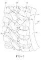
- the lugs 40 of the first circumferential row are similar in shape, but opposite in orientation, to the lugs 50 of the second circumferential row ( FIG. 2 ).
- Each lug 40 of the first circumferential row lies within a first tread half 32A ( FIG. 4 ).
- Each lug 50 of the second circumferential row lies within a second tread half 32B ( FIG. 4 ).
- the lugs 60 of the central row lie in both the first tread half 32A and second tread half 32B.
- All of the lugs 40, 50, 60 have a leading edge 41 and a trailing edge respectively.
- the leading edge 41 of a lug 40 of the first circumferential row and a majority of the leading edge of a lug 60 of the central circumferential row are defined by a single constant radius of curvature R 1 .
- the trailing edge of a lug 50 of the second circumferential row and a majority of the trailing edge of a lug 60 of the central circumferential row are defined by a single constant radius of curvature R 2 .
- the centers of the radii of curvature R 1 , R 2 are located in opposite tread halves 32A, 32B ( FIGS. 2 and 3 ).
- the tire 20 has a carcass 21 with one or more carcass plies 22 extending circumferentially about the axis rotation of the tire.
- the example tire 20 typically has 3 to 6 cord reinforced plies 22 having synthetic nylon or polyester cords.
- the carcass plies 22 are anchored around a pair of substantially inextensible annular beads 24.
- a belt structure 28 has one or more belt plies disposed radially outward from the carcass plies 22.
- the belt structure 28 provides reinforcement for a crown region (i.e., the tread 28) of the example tire 20.
- a circumferentially extending tread 32 is located radially outward of the belt structure 28.
- a sidewall portion 33 extends radially inward from each axial or lateral tread edge 33A, 33B of the tread 32 to an annular bead portion 35 having the beads 24 located therein.
- the carcass plies 22 typically have the cords oriented radially. The number of plies 22 depends on the load carrying requirements of the tire 20.
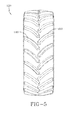
- a second example tire 120 for use with the present invention is illustrated in Fig. 5 .
- the tread of this example tire 120 generally similar to the tread of the first example tire 20 of Figs. 1 through 4 except that the tread of the second example tire 120 has only two circumferential rows of lugs 140, 150 and no central row.
- the belt structure 28 of the first example tire of Figs. 1 through 4 or the second example tire 120 of Fig. 5 comprises polyketone fibers, such as those described in US-B- 6,818,728 , which is hereby incorporated by reference into this application in its entirety. These polyketone fibers are used to form strands of yarns, which are twisted together to form a cord.
- Polyketone is a high tenacity material that may advantageously replace aramid in several applications.
- polyketone may be used in place of aramid as belt material in Radial Farm Tires, such as the first example tire 20.
- the breaking strength of a typical polyketone cord is 70 percent of the breaking strength of an aramid cord of the same construction.
- a reduction of twist in a polyketone cord may compensate for some or all of this strength difference, without severely affecting other properties.
- the below table compares properties of single end dipped 1670 dtex/1/3 cords of an aramid with a 6.9/6.9 twist construction (cord twist of 6.9 twists per inch/yarn twist of 6.9 twists per inch), a 1670 dtex/1/3 cord of polyketone yarns with a 6.9/6.9 twist construction, a 1670 dtex/1/3 cord of polyketone yarns with a 5.0/5.0 twist construction (cord twist of 5.0 twists per inch/yarn twist of 5.0 twists per inch), and a 1670 dtex/1/3 cord of polyketone yarns with a 3.0/3.0 twist construction.
- the strength of the single end dipped 6.9/6.9-twist polyketone cord is 72 percent of the aramid strength (621.3N/860.3N). As expected, the strength increases with decreasing twist-level, which results in a strength near the strength of the aramid for the 3/3-construction (836.5N/860.3N).
- the comparison of the dipped cord load at specified elongation, or Lase, values indicates that the 1 percent Lase of the aramid cord is higher than that of any of the polyketone cord constructions. However, the 3 percent Lase of the dipped aramid cord is between the values of the 3/3 and the 5/5-dipped polyketone cords (318.8N between 365.0N and 279.7N).
- Adhesion test samples were prepared by a standard peel adhesion test on 2.54 mm wide specimens. Strip adhesion samples were made by plying up a layer of fabric with both sides coated with 0.30 mm rubber coat compound to make a rubberized fabric, followed by preparation of a sandwich of two layers of the rubberized fabric separated by a mylar window sheet. The sandwich was cured for 20 min at 150°C and 2.54 mm samples were cut centered on each window in the mylar. The cured samples were then tested for adhesion between the rubberized fabrics in the area defined by the mylar window by a 180° pull on a test apparatus. Parallel samples were cured using the indicated cure cycles. Cured samples were then tested for adhesion at the indicated test conditions. A standard production compound was used for testing. The comparison of the strip adhesion force values shows that all three investigated polyketone constructions show a clearly superior adhesion behavior compared to aramid.
- Fatigue test samples were prepared by curing a pad of rubber compound in which the cords were integrated. The cured samples were then cut into 25.4 mm wide strips parallel to the cords. The samples were flexed for 2 hours in a "shoeshine" test applying a load of 355.9 N. The cords were then removed from the rubber strips. The retained strength of the flexed cords was compared to the original strength of the cord prior to flexing. Values of the retained strength were reported in percent of the strength of the cords prior to flexing. The analysis of the fatigue properties shows that polyketone cords exhibit a superior fatigue performance compared to aramid cords of the same construction.
- polyketone cords may be processed with a standard Resorcinol-Formaldehyde Latex (RFL) adhesive to reach the same adhesion level as aramid cords, which require the use of additional adhesion promoters, such as epoxy components in the adhesive, in order to assure a satisfactory level of adhesion.
- RFL Resorcinol-Formaldehyde Latex
- polyketone fibers for use with the present invention are fibers containing a ketone unit shown by the below formula as a main repeating unit.
- the polyketone fibers are made from a polyketone solution having an intrinsic viscosity of not less than 0.5 dl/g, exhibiting a crystal orientation of not less than 90 percent, a density of not less than 1.29 g/cm 3 (alternately between 1.29 to 1.31 g/cm 3 ), an elastic modulus of not less than 200 cN/dtex, and a heat shrinkage of -1 percent to 3 percent (alternately 0.1 percent to 1.5 percent).
- these example polyketone fibers may be produced by wet spinning a polyketone solution having a phase separation temperature in the range of 0 to 150° Celsius.
- the example polyketone fibers have high strength, high elastic modulus, excellent fatigue resistance, good processability, good heat resistance, dimensional stability, and excellent adhesion properties.
- the example fibers are therefore suitable for the above discussed agricultural industrial and commercial tire applications.
Abstract
Description
- The present invention is directed to a pneumatic tire. More specifically, the present invention is directed to a pneumatic tire with a belt structure comprising polyketone fibers.
- Conventional agricultural, industrial, commercial and truck tires undergo severe service and typically involve high loads. The vehicles to which the tires are mounted typically are exposed to large amounts of debris, hard packed soil conditions and high load service conditions. For example, a back hoe bucket or a front skid loader may be attached to the vehicle. The tires must be capable of engaging gravel, broken concrete, and/or hard packed dirt. Good traction in wet soil conditions is also desirable.
- A conventional agricultural, industrial, commercial, or truck tire may have a nonskid depth at the centerline of the tire of approximately one inch (2.54 cm). The conventional tire, when produced in a radial construction, may have a carcass with two to eight plies of synthetic reinforcement or a single steel ply. The synthetic plies may typically be nylon or polyester. The conventional tire may further include a belt structure with up to six plies (or belts) of high flex polyester, rayon, nylon, aramid, or steel. Agricultural and industrial tires have conventionally been fabric reinforced in order to provide better ride and handling.
- Further, the general use of polyketone fibers for tire reinforcement has been proposed.
- The present invention is directed to a pneumatic tire such as a pneumatic tire for agricultural, industrial, commercial, or truck service applications according to claim 1.
- Dependent claims refer to preferred embodiments of the invention.
- In one aspect of the present invention, the tread may include two or three circumferential rows of lugs. A first circumferential row of lugs extends axially inward from a first shoulder region of the tread. A second circumferential row of lugs extends axially inward from a second shoulder region of the tread. The second shoulder region of the tread is axially opposite the first shoulder region of the tread.
- According to one aspect of the present invention, an additional central circumferential row of lugs may be positioned axially between the first and second circumferential rows of lugs.
- In another aspect of the present invention, the polyketone yarns contain a ketone unit represented by -(CH2CH2-CO)- as a main repeating unit. The polyketone yarns may be made from a polyketone solution having an intrinsic viscosity of not less than 0.5 dl/g.
- In still another aspect of the present invention, the crystal orientation of the polyketone yarns is not less than 90 percent and/or has a density of not less than 1.29 g/cm3. Alternatively, the density may be from 1.29 to 1.31 g/cm3. The polyketone yarns may further have an elastic modulus of not less than 200 cN/dtex and a heat shrinkage of -1 percent to 3 percent. Alternatively, the heat shrinkage may be 0.1 percent to 1.5 percent.
- In one aspect of the present invention, the polyketone yarns are produced by wet spinning a polyketone solution having a phase separation temperature in the range of from 0 to 150° Celsius.
- In a yet another aspect of the present invention, the twist level of the cords and the twist level of the yarns are preferably the same. Further, the twist level of the cords may be 6.9 TPI and the twist level of the yarns may be 6.9 TPI. Alternatively, the twist level of the cords may be 3.0 TPI and the twist level of the yarns may be 3.0 TPI. As another alternative, the twist level of the cords may be 5.0 TPI and the twist level of the yarns may be 5.0 TPI. As yet another alternative, the twist level of the cords may be 8.0 TPI and the twist level of the yarns may be 8.0 TPI.
- In one aspect of the present invention, the belt structure comprising the cords has 16 EPI ("ends per inch") to 26 EPI. Alternatively, the cords may have 16 EPI to 20 EPI.
- In a further aspect of the present invention, the yarns may have a linear density in a range from 1650 dtex to 1690 dtex, such as 1670 dtex.
- In another aspect of the present invention, an example tread for use with the present invention may include two or three circumferential rows of lugs.
- The following definitions are controlling for the disclosed invention.
- "Axial" and "axially" mean lines or directions that are parallel to the axis of rotation of the tire; synonymous with "lateral" and "laterally".
- "Belt structure" means at least one, preferably at least two layers of plies (or belts) of preferably parallel cords, woven or unwoven, underlying the tread. Preferably, the one or more plies of cords are unanchored to the bead, and preferably have both left and right cord angles in the range from 16 degrees to 67 degrees with respect to the Equatorial Plane of the tire.
- "Carcass" means the tire structure apart from the belt structure, tread, undertread, and sidewall rubber over the plies, but including the beads.
- "Circumferential" means lines or directions extending along the perimeter of the surface of the annular tire parallel to the Equatorial Plane (EP) and perpendicular to the axial direction.
- "Cord" means one of the reinforcement strands which plies in the tire comprise.
- "Equatorial plane (EP)" means the plane perpendicular to the tire's axis of rotation and passing through the center of its tread.
- "Filament" refers to a single yarn.
- "Radial" and "radially" mean directions radially toward or away from the axis of rotation of the tire.
- "Undertread" refers to a layer of rubber placed between a reinforcement package and the tread rubber in a tire.
- The invention will be described by way of example and with reference to the accompanying drawings in which:
-
FIG. 1 is a perspective view of a first example tire for use with the present invention. -
FIG. 2 is a plan view of the tire ofFIG. 1 . -
FIG. 3 is an enlarged perspective, fragmentary view of a portion of the tread of the tire ofFIG. 1 . -
FIG. 4 is a cross-sectional view of the tire ofFIG. 1 taken along lines 4--4 ofFIG. 2 . -
FIG. 5 is a plan view of a second example tire for use with the present invention. - A first example radial ply pneumatic tire 20 for agricultural, industrial, commercial, or truck service is illustrated in
Figs. 1 through 4 . The example tire 20, for use with the present invention, includes a carcass 21 with at least oneply 22 reinforced by rubber coated cords, a pair of annular extendingbead cores 24. Theply 22 is wrapped about eachbead core 24 and extends therebetween. A belt structure 28 (Fig. 4 ) is disposed radially outward of theply 22 and atread 32 is disposed radially outward of the belt structure and carcass 21. Thetread 32 has atread base 34 and twolateral edges 33A, 33B. The distance halfway between thelateral edges 33A, 33B defines the tread equatorial plane EP. A plurality oflugs inner tread base 34. - The
example tread 32 features three circumferential rows of lugs. A first row extends axially inward from a first shoulder region of thetread 32. A second row extends axially inward from a second, opposite shoulder region of thetread 32. A central row is positioned between the first and second rows. The lugs 40 of the first circumferential row are similar in shape, but opposite in orientation, to thelugs 50 of the second circumferential row (FIG. 2 ). Each lug 40 of the first circumferential row lies within a first tread half 32A (FIG. 4 ). Eachlug 50 of the second circumferential row lies within a second tread half 32B (FIG. 4 ). Thelugs 60 of the central row lie in both the first tread half 32A and second tread half 32B. All of thelugs leading edge 41 and a trailing edge respectively. The leadingedge 41 of a lug 40 of the first circumferential row and a majority of the leading edge of alug 60 of the central circumferential row are defined by a single constant radius of curvature R1. The trailing edge of alug 50 of the second circumferential row and a majority of the trailing edge of alug 60 of the central circumferential row are defined by a single constant radius of curvature R2. The centers of the radii of curvature R1, R2 are located in opposite tread halves 32A, 32B (FIGS. 2 and3 ). - As shown in
FIG. 4 , the tire 20 has a carcass 21 with one or more carcass plies 22 extending circumferentially about the axis rotation of the tire. The example tire 20 typically has 3 to 6 cord reinforced plies 22 having synthetic nylon or polyester cords. The carcass plies 22 are anchored around a pair of substantially inextensibleannular beads 24. A belt structure 28 has one or more belt plies disposed radially outward from the carcass plies 22. The belt structure 28 provides reinforcement for a crown region (i.e., the tread 28) of the example tire 20. Acircumferentially extending tread 32 is located radially outward of the belt structure 28. - A
sidewall portion 33 extends radially inward from each axial orlateral tread edge 33A, 33B of thetread 32 to an annular bead portion 35 having thebeads 24 located therein. The carcass plies 22 typically have the cords oriented radially. The number ofplies 22 depends on the load carrying requirements of the tire 20. - A
second example tire 120 for use with the present invention is illustrated inFig. 5 . The tread of thisexample tire 120 generally similar to the tread of the first example tire 20 ofFigs. 1 through 4 except that the tread of thesecond example tire 120 has only two circumferential rows oflugs - In accordance with the present invention, the belt structure 28 of the first example tire of
Figs. 1 through 4 or thesecond example tire 120 ofFig. 5 comprises polyketone fibers, such as those described inUS-B- 6,818,728 , which is hereby incorporated by reference into this application in its entirety. These polyketone fibers are used to form strands of yarns, which are twisted together to form a cord. - Polyketone is a high tenacity material that may advantageously replace aramid in several applications. For example, polyketone may be used in place of aramid as belt material in Radial Farm Tires, such as the first example tire 20. The breaking strength of a typical polyketone cord is 70 percent of the breaking strength of an aramid cord of the same construction. However, a reduction of twist in a polyketone cord may compensate for some or all of this strength difference, without severely affecting other properties.
- The below table compares properties of single end dipped 1670 dtex/1/3 cords of an aramid with a 6.9/6.9 twist construction (cord twist of 6.9 twists per inch/yarn twist of 6.9 twists per inch), a 1670 dtex/1/3 cord of polyketone yarns with a 6.9/6.9 twist construction, a 1670 dtex/1/3 cord of polyketone yarns with a 5.0/5.0 twist construction (cord twist of 5.0 twists per inch/yarn twist of 5.0 twists per inch), and a 1670 dtex/1/3 cord of polyketone yarns with a 3.0/3.0 twist construction.

- The strength of the single end dipped 6.9/6.9-twist polyketone cord is 72 percent of the aramid strength (621.3N/860.3N). As expected, the strength increases with decreasing twist-level, which results in a strength near the strength of the aramid for the 3/3-construction (836.5N/860.3N). The comparison of the dipped cord load at specified elongation, or Lase, values indicates that the 1 percent Lase of the aramid cord is higher than that of any of the polyketone cord constructions. However, the 3 percent Lase of the dipped aramid cord is between the values of the 3/3 and the 5/5-dipped polyketone cords (318.8N between 365.0N and 279.7N).
- Adhesion test samples were prepared by a standard peel adhesion test on 2.54 mm wide specimens. Strip adhesion samples were made by plying up a layer of fabric with both sides coated with 0.30 mm rubber coat compound to make a rubberized fabric, followed by preparation of a sandwich of two layers of the rubberized fabric separated by a mylar window sheet. The sandwich was cured for 20 min at 150°C and 2.54 mm samples were cut centered on each window in the mylar. The cured samples were then tested for adhesion between the rubberized fabrics in the area defined by the mylar window by a 180° pull on a test apparatus. Parallel samples were cured using the indicated cure cycles. Cured samples were then tested for adhesion at the indicated test conditions. A standard production compound was used for testing. The comparison of the strip adhesion force values shows that all three investigated polyketone constructions show a clearly superior adhesion behavior compared to aramid.
- Fatigue test samples were prepared by curing a pad of rubber compound in which the cords were integrated. The cured samples were then cut into 25.4 mm wide strips parallel to the cords. The samples were flexed for 2 hours in a "shoeshine" test applying a load of 355.9 N. The cords were then removed from the rubber strips. The retained strength of the flexed cords was compared to the original strength of the cord prior to flexing. Values of the retained strength were reported in percent of the strength of the cords prior to flexing. The analysis of the fatigue properties shows that polyketone cords exhibit a superior fatigue performance compared to aramid cords of the same construction.
- Lowering of polyketone twist levels lead to a decrease of fatigue performance. However, polyketone cords of 5/5 and 3/3 constructions have comparable fatigue performance as aramid cords of 6.9/6.9 construction. Therefore, it is feasible to partially compensate for the lower strength of polyketone compared to aramid by reduction of the polyketone twist level.
- Further, polyketone cords may be processed with a standard Resorcinol-Formaldehyde Latex (RFL) adhesive to reach the same adhesion level as aramid cords, which require the use of additional adhesion promoters, such as epoxy components in the adhesive, in order to assure a satisfactory level of adhesion. Thus, a cheaper and more environmentally friendly dip formulation (i.e., RFL without epoxy) may be used.
- One example of polyketone fibers for use with the present invention are fibers containing a ketone unit shown by the below formula as a main repeating unit. The polyketone fibers are made from a polyketone solution having an intrinsic viscosity of not less than 0.5 dl/g, exhibiting a crystal orientation of not less than 90 percent, a density of not less than 1.29 g/cm3 (alternately between 1.29 to 1.31 g/cm3), an elastic modulus of not less than 200 cN/dtex, and a heat shrinkage of -1 percent to 3 percent (alternately 0.1 percent to 1.5 percent).

- Further, these example polyketone fibers may be produced by wet spinning a polyketone solution having a phase separation temperature in the range of 0 to 150° Celsius. The example polyketone fibers have high strength, high elastic modulus, excellent fatigue resistance, good processability, good heat resistance, dimensional stability, and excellent adhesion properties. The example fibers are therefore suitable for the above discussed agricultural industrial and commercial tire applications.
Claims (15)
- A pneumatic tire having an axis of rotation, the pneumatic tire comprising: a carcass (21) having at least one reinforced ply (22);a tread (32) disposed radially outward of the carcass (21);and a belt structure (28) disposed radially between the carcass (21) and the tread (32), the belt structure (28) comprising cords of at least three strands of twisted polyketone yarn, the twisted polyketone yarns having a linear density from 1570 dtex to 1770 dtex and a twist level from 3.0 TPI (turns per inch) to 8.0 TPI, the cords having a twist level from 3.0 TPI to 8.0 TPI and a twist direction opposite to a twist direction of the polyketone yarns.
- The pneumatic tire of claim 1 wherein the twist level of the cords is the same as the twist level of the polyketone yarns.
- The pneumatic tire of claim 1 or 2 wherein the cords form a ply of the belt structure (28), the construction of the ply comprising the cords having 16 EPI to 26 EPI.
- The pneumatic tire of at least one of the previous claims wherein the tread (32) includes two or three circumferential rows of lugs (40, 50, 60).
- The pneumatic tire of at least one of the previous claims, wherein the polyketone yarns contain a ketone unit represented by -(CH2CH2-CO)- as a main repeating unit.
- The pneumatic tire of at least one of the previous calims wherein the polyketone yarns have at least one of:a density of not less than 1.29 g/cm3; and/oran elastic modulus of not less than 200 cN/dtex; and/ora heat shrinkage of -1 percent to 3 percent.
- The pneumatic tire of at least one of the previous claims wherein the polyketone yarns have a linear density of 1650 dtex, to 1690 dtex such as 1670 dtex.
- The pneumatic tire of at least one of the previous claims wherein the cords form a ply of the belt structure (28), the construction of the ply comprising the cords having 16 to 20 EPI, such as 18 EPI.
- The pneumatic tire of at least one of the previous claims wherein the twist level of the cords is 6.9 TPI and the twist level of the polyketone yarns is 6.9 TPI.
- The pneumatic tire of at least one of the previous claims wherein the twist level of the cords is 3.0 TPI and the twist level of the polyketone yarns is 3.0 TPI.
- The pneumatic tire of at least one of the previous claims wherein the twist level of the cords is 5.0 TPI and the twist level of the polyketone yarns is 5.0 TPI.
- The pneumatic tire of at least one of the previous claims wherein the twist level of the cords is 8.0 TPI and the twist level of the polyketone yarns is 8.0 TPI.
- The pneumatic tire of at least one of the previous claims wherein each cord consists of three strands of twisted polyketone yarns.
- The pneumatic tire of claim 1 wherein the pneumatic tire is an agricultural tire.
- The pneumatic tire of claim 1 wherein the pneumatic tire is an industrial service tire.
Applications Claiming Priority (1)
| Application Number | Priority Date | Filing Date | Title |
|---|---|---|---|
| US12/177,241 US20100018625A1 (en) | 2008-07-22 | 2008-07-22 | Pneumatic tire with polyketone belt structure |
Publications (2)
| Publication Number | Publication Date |
|---|---|
| EP2147804A1 true EP2147804A1 (en) | 2010-01-27 |
| EP2147804B1 EP2147804B1 (en) | 2011-05-25 |
Family
ID=41076822
Family Applications (1)
| Application Number | Title | Priority Date | Filing Date |
|---|---|---|---|
| EP09165489A Active EP2147804B1 (en) | 2008-07-22 | 2009-07-15 | A pneumatic tire with polyketone belt structure |
Country Status (4)
| Country | Link |
|---|---|
| US (1) | US20100018625A1 (en) |
| EP (1) | EP2147804B1 (en) |
| JP (1) | JP2010023833A (en) |
| AT (1) | ATE510707T1 (en) |
Cited By (1)
| Publication number | Priority date | Publication date | Assignee | Title |
|---|---|---|---|---|
| WO2021156558A1 (en) * | 2020-02-06 | 2021-08-12 | Compagnie Generale Des Etablissements Michelin | Tyre for an agricultural vehicle, comprising a hybrid carcass reinforcing element |
Families Citing this family (3)
| Publication number | Priority date | Publication date | Assignee | Title |
|---|---|---|---|---|
| FR2974583B1 (en) * | 2011-04-28 | 2013-06-14 | Michelin Soc Tech | ARAMIDE-POLYCETONE COMPOSITE TEXTILE CABLE |
| US8905097B2 (en) | 2012-02-01 | 2014-12-09 | Bridgestone Americas Tire Operations, Llc | Agricultural tire tread |
| US10160265B2 (en) | 2013-12-23 | 2018-12-25 | Bridgestone Americas Tire Operations, Llc | Tire with reinforced tread |
Citations (8)
| Publication number | Priority date | Publication date | Assignee | Title |
|---|---|---|---|---|
| US6818728B2 (en) | 2001-02-27 | 2004-11-16 | Asahi Kasei Kabushiki Kaisha | Polyketone fiber and process for producing the same |
| US20050126673A1 (en) * | 2000-05-30 | 2005-06-16 | Sumitomo Rubber Industries, Ltd. | Pneumatic tire |
| EP1609623A1 (en) * | 2003-04-02 | 2005-12-28 | Bridgestone Corporation | Rubberized fibrous material and pneumatic tire |
| US20070012394A1 (en) * | 2005-07-13 | 2007-01-18 | The Yokohama Rubber Co., Ltd. | Pneumatic radial tire |
| WO2007108510A1 (en) * | 2006-03-23 | 2007-09-27 | Bridgestone Corporation | Pneumatic safety tire |
| EP1839907A1 (en) * | 2005-01-21 | 2007-10-03 | Bridgestone Corporation | Pneumatic radial tire |
| WO2007122984A1 (en) * | 2006-04-17 | 2007-11-01 | Bridgestone Corporation | Pneumatic tire |
| EP1925467A1 (en) * | 2005-08-26 | 2008-05-28 | The Yokohama Rubber Co., Ltd. | Pneumatic tire |
Family Cites Families (6)
| Publication number | Priority date | Publication date | Assignee | Title |
|---|---|---|---|---|
| US7015303B1 (en) * | 1998-08-10 | 2006-03-21 | Asahi Kasei Kabushiki Kaisha | Polyketone solution |
| US6851463B1 (en) * | 1999-04-08 | 2005-02-08 | Alliedsignal Inc. | Composite comprising organic fibers having a low twist multiplier and improved compressive modulus |
| WO2002096673A1 (en) * | 2001-05-25 | 2002-12-05 | Pirelli Pneumatici S.P.A. | Rubberized fabric and pneumatic tire comprising said rubberized fabric |
| JP3902211B2 (en) * | 2002-08-29 | 2007-04-04 | 旭化成せんい株式会社 | Polyketone fiber and method for producing the same |
| JP4950517B2 (en) * | 2006-03-01 | 2012-06-13 | 株式会社ブリヂストン | Pneumatic radial tire |
| JP4817948B2 (en) * | 2006-04-17 | 2011-11-16 | 株式会社ブリヂストン | Pneumatic tire |
-
2008
- 2008-07-22 US US12/177,241 patent/US20100018625A1/en not_active Abandoned
-
2009
- 2009-07-15 EP EP09165489A patent/EP2147804B1/en active Active
- 2009-07-15 AT AT09165489T patent/ATE510707T1/en not_active IP Right Cessation
- 2009-07-22 JP JP2009171235A patent/JP2010023833A/en active Pending
Patent Citations (8)
| Publication number | Priority date | Publication date | Assignee | Title |
|---|---|---|---|---|
| US20050126673A1 (en) * | 2000-05-30 | 2005-06-16 | Sumitomo Rubber Industries, Ltd. | Pneumatic tire |
| US6818728B2 (en) | 2001-02-27 | 2004-11-16 | Asahi Kasei Kabushiki Kaisha | Polyketone fiber and process for producing the same |
| EP1609623A1 (en) * | 2003-04-02 | 2005-12-28 | Bridgestone Corporation | Rubberized fibrous material and pneumatic tire |
| EP1839907A1 (en) * | 2005-01-21 | 2007-10-03 | Bridgestone Corporation | Pneumatic radial tire |
| US20070012394A1 (en) * | 2005-07-13 | 2007-01-18 | The Yokohama Rubber Co., Ltd. | Pneumatic radial tire |
| EP1925467A1 (en) * | 2005-08-26 | 2008-05-28 | The Yokohama Rubber Co., Ltd. | Pneumatic tire |
| WO2007108510A1 (en) * | 2006-03-23 | 2007-09-27 | Bridgestone Corporation | Pneumatic safety tire |
| WO2007122984A1 (en) * | 2006-04-17 | 2007-11-01 | Bridgestone Corporation | Pneumatic tire |
Cited By (3)
| Publication number | Priority date | Publication date | Assignee | Title |
|---|---|---|---|---|
| WO2021156558A1 (en) * | 2020-02-06 | 2021-08-12 | Compagnie Generale Des Etablissements Michelin | Tyre for an agricultural vehicle, comprising a hybrid carcass reinforcing element |
| CN115066340A (en) * | 2020-02-06 | 2022-09-16 | 米其林集团总公司 | Agricultural vehicle tire comprising a hybrid carcass reinforcing element |
| CN115066340B (en) * | 2020-02-06 | 2023-11-03 | 米其林集团总公司 | Agricultural vehicle tire including hybrid carcass reinforcing elements |
Also Published As
| Publication number | Publication date |
|---|---|
| JP2010023833A (en) | 2010-02-04 |
| ATE510707T1 (en) | 2011-06-15 |
| EP2147804B1 (en) | 2011-05-25 |
| US20100018625A1 (en) | 2010-01-28 |
Similar Documents
| Publication | Publication Date | Title |
|---|---|---|
| US20090090447A1 (en) | Tire cord reinforcement | |
| US9902204B2 (en) | Tyre with lightened belt structure including steel monofilaments | |
| JP3699523B2 (en) | Radial medium truck tire | |
| US11433709B2 (en) | Radial tire having a very thin belt structure | |
| US20080105352A1 (en) | Reduced weight aircraft tire | |
| US20180022160A1 (en) | Radial tire having an improved belt structure | |
| US10471774B2 (en) | Radial tire having a lightweight belt structure | |
| US20090107609A1 (en) | High Extensible Cut-Resistant Barrier | |
| EP2439080B1 (en) | A pneumatic tire with a woven or knitted reinforcement | |
| EP0929405A1 (en) | Pneumatic tire | |
| KR20160037919A (en) | Radial tyre having a lightweight belt structure | |
| EP3365187B1 (en) | Hybrid cord as carcass reinforcement in bias tire | |
| US20240051344A1 (en) | Reduced weight aircraft tire | |
| CN105517814B (en) | Improve the method for the performance of the tire for wheel of vehicle and the tire for wheel of vehicle | |
| EP2439084B1 (en) | A pneumatic tire with a knitted fabric as reinforcing structure | |
| US11186122B2 (en) | Reduced weight aircraft tire | |
| EP3898275B1 (en) | Tyre for vehicle wheels | |
| EP2439082A2 (en) | A tire with a metallic belt reinforcement | |
| EP2147805A2 (en) | Pneumatic tire | |
| EP2147804B1 (en) | A pneumatic tire with polyketone belt structure | |
| US6634398B1 (en) | Chip resistance tire | |
| EP1547817A2 (en) | Pneumatic tire with blended composite fiber cords | |
| EP3081396B1 (en) | A bidirectional monobelt construction for a pneumatic tire | |
| EP0448901B1 (en) | Bias ply aircraft tire | |
| US6041839A (en) | Metallic 4+3 cord for the reinforcement of elastomers |
Legal Events
| Date | Code | Title | Description |
|---|---|---|---|
| PUAI | Public reference made under article 153(3) epc to a published international application that has entered the european phase |
Free format text: ORIGINAL CODE: 0009012 |
|
| AK | Designated contracting states |
Kind code of ref document: A1 Designated state(s): AT BE BG CH CY CZ DE DK EE ES FI FR GB GR HR HU IE IS IT LI LT LU LV MC MK MT NL NO PL PT RO SE SI SK SM TR |
|
| AX | Request for extension of the european patent |
Extension state: AL BA RS |
|
| 17P | Request for examination filed |
Effective date: 20100727 |
|
| GRAP | Despatch of communication of intention to grant a patent |
Free format text: ORIGINAL CODE: EPIDOSNIGR1 |
|
| GRAS | Grant fee paid |
Free format text: ORIGINAL CODE: EPIDOSNIGR3 |
|
| GRAA | (expected) grant |
Free format text: ORIGINAL CODE: 0009210 |
|
| AK | Designated contracting states |
Kind code of ref document: B1 Designated state(s): AT BE BG CH CY CZ DE DK EE ES FI FR GB GR HR HU IE IS IT LI LT LU LV MC MK MT NL NO PL PT RO SE SI SK SM TR |
|
| REG | Reference to a national code |
Ref country code: GB Ref legal event code: FG4D |
|
| REG | Reference to a national code |
Ref country code: CH Ref legal event code: EP |
|
| REG | Reference to a national code |
Ref country code: IE Ref legal event code: FG4D |
|
| REG | Reference to a national code |
Ref country code: DE Ref legal event code: R096 Ref document number: 602009001350 Country of ref document: DE Effective date: 20110707 |
|
| REG | Reference to a national code |
Ref country code: NL Ref legal event code: VDEP Effective date: 20110525 |
|
| PG25 | Lapsed in a contracting state [announced via postgrant information from national office to epo] |
Ref country code: NO Free format text: LAPSE BECAUSE OF FAILURE TO SUBMIT A TRANSLATION OF THE DESCRIPTION OR TO PAY THE FEE WITHIN THE PRESCRIBED TIME-LIMIT Effective date: 20110825 Ref country code: HR Free format text: LAPSE BECAUSE OF FAILURE TO SUBMIT A TRANSLATION OF THE DESCRIPTION OR TO PAY THE FEE WITHIN THE PRESCRIBED TIME-LIMIT Effective date: 20110525 Ref country code: PT Free format text: LAPSE BECAUSE OF FAILURE TO SUBMIT A TRANSLATION OF THE DESCRIPTION OR TO PAY THE FEE WITHIN THE PRESCRIBED TIME-LIMIT Effective date: 20110926 Ref country code: SE Free format text: LAPSE BECAUSE OF FAILURE TO SUBMIT A TRANSLATION OF THE DESCRIPTION OR TO PAY THE FEE WITHIN THE PRESCRIBED TIME-LIMIT Effective date: 20110525 Ref country code: LT Free format text: LAPSE BECAUSE OF FAILURE TO SUBMIT A TRANSLATION OF THE DESCRIPTION OR TO PAY THE FEE WITHIN THE PRESCRIBED TIME-LIMIT Effective date: 20110525 |
|
| PG25 | Lapsed in a contracting state [announced via postgrant information from national office to epo] |
Ref country code: SI Free format text: LAPSE BECAUSE OF FAILURE TO SUBMIT A TRANSLATION OF THE DESCRIPTION OR TO PAY THE FEE WITHIN THE PRESCRIBED TIME-LIMIT Effective date: 20110525 Ref country code: IS Free format text: LAPSE BECAUSE OF FAILURE TO SUBMIT A TRANSLATION OF THE DESCRIPTION OR TO PAY THE FEE WITHIN THE PRESCRIBED TIME-LIMIT Effective date: 20110925 Ref country code: ES Free format text: LAPSE BECAUSE OF FAILURE TO SUBMIT A TRANSLATION OF THE DESCRIPTION OR TO PAY THE FEE WITHIN THE PRESCRIBED TIME-LIMIT Effective date: 20110905 Ref country code: CY Free format text: LAPSE BECAUSE OF FAILURE TO SUBMIT A TRANSLATION OF THE DESCRIPTION OR TO PAY THE FEE WITHIN THE PRESCRIBED TIME-LIMIT Effective date: 20110525 Ref country code: LV Free format text: LAPSE BECAUSE OF FAILURE TO SUBMIT A TRANSLATION OF THE DESCRIPTION OR TO PAY THE FEE WITHIN THE PRESCRIBED TIME-LIMIT Effective date: 20110525 Ref country code: AT Free format text: LAPSE BECAUSE OF FAILURE TO SUBMIT A TRANSLATION OF THE DESCRIPTION OR TO PAY THE FEE WITHIN THE PRESCRIBED TIME-LIMIT Effective date: 20110525 Ref country code: BE Free format text: LAPSE BECAUSE OF FAILURE TO SUBMIT A TRANSLATION OF THE DESCRIPTION OR TO PAY THE FEE WITHIN THE PRESCRIBED TIME-LIMIT Effective date: 20110525 Ref country code: FI Free format text: LAPSE BECAUSE OF FAILURE TO SUBMIT A TRANSLATION OF THE DESCRIPTION OR TO PAY THE FEE WITHIN THE PRESCRIBED TIME-LIMIT Effective date: 20110525 Ref country code: GR Free format text: LAPSE BECAUSE OF FAILURE TO SUBMIT A TRANSLATION OF THE DESCRIPTION OR TO PAY THE FEE WITHIN THE PRESCRIBED TIME-LIMIT Effective date: 20110826 |
|
| PG25 | Lapsed in a contracting state [announced via postgrant information from national office to epo] |
Ref country code: NL Free format text: LAPSE BECAUSE OF FAILURE TO SUBMIT A TRANSLATION OF THE DESCRIPTION OR TO PAY THE FEE WITHIN THE PRESCRIBED TIME-LIMIT Effective date: 20110525 Ref country code: MT Free format text: LAPSE BECAUSE OF FAILURE TO SUBMIT A TRANSLATION OF THE DESCRIPTION OR TO PAY THE FEE WITHIN THE PRESCRIBED TIME-LIMIT Effective date: 20110525 |
|
| PG25 | Lapsed in a contracting state [announced via postgrant information from national office to epo] |
Ref country code: EE Free format text: LAPSE BECAUSE OF FAILURE TO SUBMIT A TRANSLATION OF THE DESCRIPTION OR TO PAY THE FEE WITHIN THE PRESCRIBED TIME-LIMIT Effective date: 20110525 Ref country code: CZ Free format text: LAPSE BECAUSE OF FAILURE TO SUBMIT A TRANSLATION OF THE DESCRIPTION OR TO PAY THE FEE WITHIN THE PRESCRIBED TIME-LIMIT Effective date: 20110525 |
|
| PG25 | Lapsed in a contracting state [announced via postgrant information from national office to epo] |
Ref country code: SK Free format text: LAPSE BECAUSE OF FAILURE TO SUBMIT A TRANSLATION OF THE DESCRIPTION OR TO PAY THE FEE WITHIN THE PRESCRIBED TIME-LIMIT Effective date: 20110525 Ref country code: PL Free format text: LAPSE BECAUSE OF FAILURE TO SUBMIT A TRANSLATION OF THE DESCRIPTION OR TO PAY THE FEE WITHIN THE PRESCRIBED TIME-LIMIT Effective date: 20110525 Ref country code: MC Free format text: LAPSE BECAUSE OF NON-PAYMENT OF DUE FEES Effective date: 20110731 |
|
| PLBE | No opposition filed within time limit |
Free format text: ORIGINAL CODE: 0009261 |
|
| STAA | Information on the status of an ep patent application or granted ep patent |
Free format text: STATUS: NO OPPOSITION FILED WITHIN TIME LIMIT |
|
| REG | Reference to a national code |
Ref country code: IE Ref legal event code: MM4A |
|
| 26N | No opposition filed |
Effective date: 20120228 |
|
| REG | Reference to a national code |
Ref country code: DE Ref legal event code: R097 Ref document number: 602009001350 Country of ref document: DE Effective date: 20120228 |
|
| PG25 | Lapsed in a contracting state [announced via postgrant information from national office to epo] |
Ref country code: IE Free format text: LAPSE BECAUSE OF NON-PAYMENT OF DUE FEES Effective date: 20110715 |
|
| PGFP | Annual fee paid to national office [announced via postgrant information from national office to epo] |
Ref country code: LU Payment date: 20120720 Year of fee payment: 4 |
|
| PG25 | Lapsed in a contracting state [announced via postgrant information from national office to epo] |
Ref country code: MK Free format text: LAPSE BECAUSE OF FAILURE TO SUBMIT A TRANSLATION OF THE DESCRIPTION OR TO PAY THE FEE WITHIN THE PRESCRIBED TIME-LIMIT Effective date: 20110525 |
|
| PG25 | Lapsed in a contracting state [announced via postgrant information from national office to epo] |
Ref country code: SM Free format text: LAPSE BECAUSE OF FAILURE TO SUBMIT A TRANSLATION OF THE DESCRIPTION OR TO PAY THE FEE WITHIN THE PRESCRIBED TIME-LIMIT Effective date: 20110525 |
|
| PG25 | Lapsed in a contracting state [announced via postgrant information from national office to epo] |
Ref country code: BG Free format text: LAPSE BECAUSE OF FAILURE TO SUBMIT A TRANSLATION OF THE DESCRIPTION OR TO PAY THE FEE WITHIN THE PRESCRIBED TIME-LIMIT Effective date: 20110825 |
|
| PG25 | Lapsed in a contracting state [announced via postgrant information from national office to epo] |
Ref country code: TR Free format text: LAPSE BECAUSE OF FAILURE TO SUBMIT A TRANSLATION OF THE DESCRIPTION OR TO PAY THE FEE WITHIN THE PRESCRIBED TIME-LIMIT Effective date: 20110525 |
|
| PG25 | Lapsed in a contracting state [announced via postgrant information from national office to epo] |
Ref country code: HU Free format text: LAPSE BECAUSE OF FAILURE TO SUBMIT A TRANSLATION OF THE DESCRIPTION OR TO PAY THE FEE WITHIN THE PRESCRIBED TIME-LIMIT Effective date: 20110525 |
|
| REG | Reference to a national code |
Ref country code: CH Ref legal event code: PL |
|
| GBPC | Gb: european patent ceased through non-payment of renewal fee |
Effective date: 20130715 |
|
| PG25 | Lapsed in a contracting state [announced via postgrant information from national office to epo] |
Ref country code: LI Free format text: LAPSE BECAUSE OF NON-PAYMENT OF DUE FEES Effective date: 20130731 Ref country code: CH Free format text: LAPSE BECAUSE OF NON-PAYMENT OF DUE FEES Effective date: 20130731 Ref country code: GB Free format text: LAPSE BECAUSE OF NON-PAYMENT OF DUE FEES Effective date: 20130715 |
|
| REG | Reference to a national code |
Ref country code: FR Ref legal event code: PLFP Year of fee payment: 7 |
|
| PG25 | Lapsed in a contracting state [announced via postgrant information from national office to epo] |
Ref country code: LU Free format text: LAPSE BECAUSE OF NON-PAYMENT OF DUE FEES Effective date: 20130715 |
|
| PGFP | Annual fee paid to national office [announced via postgrant information from national office to epo] |
Ref country code: FR Payment date: 20150624 Year of fee payment: 7 |
|
| PGFP | Annual fee paid to national office [announced via postgrant information from national office to epo] |
Ref country code: DE Payment date: 20150731 Year of fee payment: 7 |
|
| PGFP | Annual fee paid to national office [announced via postgrant information from national office to epo] |
Ref country code: IT Payment date: 20150716 Year of fee payment: 7 |
|
| REG | Reference to a national code |
Ref country code: DE Ref legal event code: R119 Ref document number: 602009001350 Country of ref document: DE |
|
| PG25 | Lapsed in a contracting state [announced via postgrant information from national office to epo] |
Ref country code: FR Free format text: LAPSE BECAUSE OF NON-PAYMENT OF DUE FEES Effective date: 20160801 Ref country code: DE Free format text: LAPSE BECAUSE OF NON-PAYMENT OF DUE FEES Effective date: 20170201 |
|
| REG | Reference to a national code |
Ref country code: FR Ref legal event code: ST Effective date: 20170331 |
|
| PG25 | Lapsed in a contracting state [announced via postgrant information from national office to epo] |
Ref country code: IT Free format text: LAPSE BECAUSE OF NON-PAYMENT OF DUE FEES Effective date: 20160715 |