EP2147758B1 - Razor handle - Google Patents
Razor handle Download PDFInfo
- Publication number
- EP2147758B1 EP2147758B1 EP09176189.0A EP09176189A EP2147758B1 EP 2147758 B1 EP2147758 B1 EP 2147758B1 EP 09176189 A EP09176189 A EP 09176189A EP 2147758 B1 EP2147758 B1 EP 2147758B1
- Authority
- EP
- European Patent Office
- Prior art keywords
- handle
- pod
- razor
- battery
- molded
- Prior art date
- Legal status (The legal status is an assumption and is not a legal conclusion. Google has not performed a legal analysis and makes no representation as to the accuracy of the status listed.)
- Active
Links
Images


Classifications
-
- B—PERFORMING OPERATIONS; TRANSPORTING
- B26—HAND CUTTING TOOLS; CUTTING; SEVERING
- B26B—HAND-HELD CUTTING TOOLS NOT OTHERWISE PROVIDED FOR
- B26B21/00—Razors of the open or knife type; Safety razors or other shaving implements of the planing type; Hair-trimming devices involving a razor-blade; Equipment therefor
- B26B21/40—Details or accessories
- B26B21/52—Handles, e.g. tiltable, flexible
- B26B21/521—Connection details, e.g. connection to razor heads
-
- B—PERFORMING OPERATIONS; TRANSPORTING
- B26—HAND CUTTING TOOLS; CUTTING; SEVERING
- B26B—HAND-HELD CUTTING TOOLS NOT OTHERWISE PROVIDED FOR
- B26B21/00—Razors of the open or knife type; Safety razors or other shaving implements of the planing type; Hair-trimming devices involving a razor-blade; Equipment therefor
- B26B21/08—Razors of the open or knife type; Safety razors or other shaving implements of the planing type; Hair-trimming devices involving a razor-blade; Equipment therefor involving changeable blades
- B26B21/14—Safety razors with one or more blades arranged transversely to the handle
- B26B21/38—Safety razors with one or more blades arranged transversely to the handle with provision for reciprocating the blade by means other than rollers
-
- B—PERFORMING OPERATIONS; TRANSPORTING
- B26—HAND CUTTING TOOLS; CUTTING; SEVERING
- B26B—HAND-HELD CUTTING TOOLS NOT OTHERWISE PROVIDED FOR
- B26B21/00—Razors of the open or knife type; Safety razors or other shaving implements of the planing type; Hair-trimming devices involving a razor-blade; Equipment therefor
- B26B21/40—Details or accessories
- B26B21/52—Handles, e.g. tiltable, flexible
Definitions
- the present invention relates generally to handles for shaving implements, and, more particularly, to a process for manufacturing a handle having a battery-powered device therein.
- Modern shaving implements can include a plurality of blades disposed within a razor cartridge.
- the razor cartridge is, in turn, mounted on a handle during use.
- Some safety razors have a disposable razor cartridge that is selectively detachable to a reusable handle, while others have a handle and a razor cartridge that are manufactured as a single, disposable unit.
- US-A-2004/0216311 discloses a razor handle assembly having a first handle section including a first solid body portion and a second handle section including a second solid body portion, the first and second body portions generally being mirror images of one another.
- the first and second handle sections are coupled together and cooperate to form a closed end and a generally opposite open end and a receiving space therebetween.
- a head assembly is interposed between the first and second body sections at the open end and includes a retainer for releasably mounting a disposable razor cartridge to a razor handle.
- a core is positioned in the receiving space between the first and second body portions and has an end adjacent to the closed end formed by the first and second handle sections.
- a vibratory shaver comprising two molded handle portions encasing a battery-powered device and a battery.
- a razor cartridge connecting element is mounted onto or molded into the exterior of one of the molded handle portions.
- injection molding is a relatively inexpensive method of forming a contoured handle having any number of features.
- the handle can be formed through a series of injection molding steps, which can provide additional benefits, such as, but not limited, to several colors, textures, elasticities, and/or features that can not be achieved during a single injection molding process ( US-3-6 749 788 ).
- Handles that are formed using multiple injection molding steps allow for additional features to be captured between the molded portions of the handle.
- these handles include cartridge-connecting members, which are operable to connect the razor cartridge to the razor handle, and which typically require several moving features made from distinct parts that are assembled. Because the cartridge-connecting members have moving features that are assembled, it is often impossible or at least not conducive to injection mold an entire handle through a series of injection molding steps.
- a razor handle includes the features of claim 1. Individual embodiments of the invention are the subject matter of the dependent claims.
- first handle portion can be formed quickly, and inexpensively, in a manner that allows for any number of features, colors, and contours.
- connecting pod may be assembled in a separate operation, then attached to the first handle portion.
- a razor handle 10 includes a first handle portion 12, and connecting pod 14.
- the first handle portion 12 includes a first molded portion 16, a battery-powered device 18, a second molded portion 20, and an auxiliary cavity 22.
- the connecting pod 14 includes a handle-connecting member 24 and a razor cartridge-connecting member 26.
- the battery-powered device 18 can be any device that provides some additional benefit to the end user.
- the battery-powered device 18 is a motor that spins an eccentric weight 32.
- the battery-powered device 18 further includes wiring, switch(es), sensor(s), and/or other additional electronic components.
- the battery-powered device 18 is connected to a battery 30.
- the second molded portion 20 can be formed of thermoplastic rubber ("TPE"), and preferably VYRAM® rubber 9211-35W906 that is commercially available through Advanced Elastomer Systems (AES) of Akron, OH, USA.
- TPE thermoplastic rubber
- AES Advanced Elastomer Systems
- the TPE material identified above has desirable hardness (45 Shore A), specific gravity (.92), (ultimate) tensile strength (3.0 MPa), (ultimate) elongation (450%).
- the TPE material also has desirable compressive qualities, which are useful for creating various razor handle features, such as, but not limited to, gripping structures 34 (discussed infra ).
- any suitable material known to those of skill in the art can be used in place of the above-identified material.
- the second molded portion 20 may also be utilized to form additional features on the first handle portion 12.
- the second molded portion 20 may form at least a portion of the auxiliary cavity 22, cavity 28, gripping structures 34 (see e.g., FIG. 1 ), On/Off buttons 36 for the battery-powered device 18 (see e.g., FIG. 1 ), and/or pod connecting members 38 (discussed infra ).
- the second molded portion 20 may be a single, unitary piece, or may be several separate elements, as shown in FIG. 1 .
- the first handle portion 12 can form a cavity 28 sized for receiving at least a portion of a battery 30.
- the cavity 28 may be formed of the first molded portion 16 and/or the second molded portion 20. Using the materials listed above, it is preferable that the cavity 28 be formed primarily of the first molded portion 16 because of its rigidity and hardness.
- the GFPP material provides a more stable cavity 28 material that is less likely to undesirably change shape during the life of the first handle portion 12 than does the TPE.
- the cavity 28 is sized for receiving at least a portion of a standard, AAA-sized battery, as shown in FIG. 6. However, the cavity 28 may also be sized to receive at least a portion of any sized battery 30.
- the cavity 28 is oriented within the razor handle 10 such that the razor handle 10 is ergonomically shaped.
- a battery 30 may be entirely encased in, or in between, the first and/or second molded portions of the first handle portion. Such a situation may be especially useful in a disposable-type razor that is intended to be discarded once the battery 30 has expired.
- the first handle portion 12 includes an auxiliary cavity 22.
- the auxiliary cavity 22 can include a pod-connecting member 38, and is sized and shaped to receive a connecting pod 14.
- the pod-connecting member 38 may include, for example, one or more slots 40 in the auxiliary cavity 22 into which complimentary handle-connecting member(s) 24 (discussed infra ) on the connecting pod 14 fit.
- the auxiliary cavity 22 can be one or more protrusions (not shown) that fit into complimentary slots (not shown) on the connecting pod 14.
- the auxiliary cavity 22 is typically located near one end 42 of the first handle portion 12. Therefore, when the connecting pod 14 is attached, the cartridge-connecting members 26 (discussed infra ) on the connecting pod 14, the razor cartridge 44 can be conveniently releasably secured to the razor handle.
- the auxiliary cavity 22, naturally, is sized and shaped to receive the connecting pod 14.
- the connecting pod 14 is typically pre-assembled, and includes a cartridge-connecting member 26, and a handle-connecting member 24.
- the connecting pod 14 further includes a release mechanism 46 and a biasing member 48.
- the biasing member 48 is operable to urge the razor cartridge 44 toward a rest position (shown in FIG. 3 ), but is able to allow the razor cartridge 44 to pivot relative to the handle (not shown) when forces are placed on the razor cartridge 44.
- the biasing member 48 is a spring-loaded plunger 50; however, any suitable biasing member 48, such as a leaf spring (not shown) may be utilized.
- the handle-connecting member 24 of the connecting pod 14, and the pod-connecting member 38 of the first handle portion 12 cooperate to connect the connecting pod 14 and the first handle portion 12. Together, once connected, the connecting pod 14 and the first handle portion 12 are typically not intended to be separated during normal use.
- the cartridge-connecting member 26 may any one of numerous types of cartridge connector members 26 known in the art, and may connect to the cartridge 44 in either a fixed manner, or a pivotal manner.
- the cartridge-connecting member 26 includes at least two journal bearings 52 which mate with complimentary connectors 54 on an associated razor cartridge 44.
- the razor cartridge 44 can, in some embodiments, pivot relative to the razor handle 10.
- an inter-connect member may be attached to the razor cartridge 44 such that the razor cartridge 44 pivots relative to the inter-connect member (and, accordingly, the handle 10).
- the inter-connect member is fixedly attached in any suitable manner to the connecting pod 14.
- the release button 46 may be of any suitable type. In the embodiment shown, the release button 46 pivots the cartridge-connecting members 26 inward, which, in turn, releases the razor cartridge 44.
- the handle-connecting member(s) 24 are complimentary to the pod-connecting member(s) 38 of the first handle portion 12.
- the handle-connecting member(s) 24, as noted above, may be any suitable type and may be "male” or "female”.
- One method for making the razor handle 10 of the present invention includes the following steps.
- the first molded portion 16 of a first handle portion 12 is injection molded.
- the battery-powered device 18 is then secured to,the first molded portion 12 of the first handle portion 12.
- the second molded portion 20 of the first handle portion 12 is then injection molded such that at least a portion of the battery-powered device 18 is encased in the first handle portion 12 (e.g., between the first and second molded portions 16, 20).
- the connecting pod 14 is assembled and attached to the first handle portion 12 by connecting the pod-connecting member(s) 38 of the first handle portion 12 to the handle-connecting member(s) 24 of the connecting pod 14.
- the first handle portion 12 may include additional molded portion(s).
- the additional portion(s) may be formed at any point in time during before, during or after the two (2) injection molding processes described in the preceding paragraph.
- the user couples a razor cartridge 44 to the cartridge-connecting member(s) 26 of the connecting pod 14, activates the battery-powered device 18, and proceeds to shave unwanted hair from a surface.
- the user selectively de-activates the battery-powered device 18 when the razor handle 10 is not in use.
Abstract
Description
- The present invention relates generally to handles for shaving implements, and, more particularly, to a process for manufacturing a handle having a battery-powered device therein.
- Modern shaving implements can include a plurality of blades disposed within a razor cartridge. The razor cartridge is, in turn, mounted on a handle during use. Some safety razors have a disposable razor cartridge that is selectively detachable to a reusable handle, while others have a handle and a razor cartridge that are manufactured as a single, disposable unit.
-
US-A-2004/0216311 discloses a razor handle assembly having a first handle section including a first solid body portion and a second handle section including a second solid body portion, the first and second body portions generally being mirror images of one another. The first and second handle sections are coupled together and cooperate to form a closed end and a generally opposite open end and a receiving space therebetween. A head assembly is interposed between the first and second body sections at the open end and includes a retainer for releasably mounting a disposable razor cartridge to a razor handle. A core is positioned in the receiving space between the first and second body portions and has an end adjacent to the closed end formed by the first and second handle sections. - Furthermore, from
US-A-2004/0172831 a vibratory shaver is known comprising two molded handle portions encasing a battery-powered device and a battery. A razor cartridge connecting element is mounted onto or molded into the exterior of one of the molded handle portions. - In those handles that connect to a selectively detachable razor cartridge, it has been found that injection molding at least a portion of the handle has certain advantages. For example, injection molding is a relatively inexpensive method of forming a contoured handle having any number of features. In addition, the handle can be formed through a series of injection molding steps, which can provide additional benefits, such as, but not limited, to several colors, textures, elasticities, and/or features that can not be achieved during a single injection molding process (
US-3-6 749 788 - Handles that are formed using multiple injection molding steps allow for additional features to be captured between the molded portions of the handle. However, these handles include cartridge-connecting members, which are operable to connect the razor cartridge to the razor handle, and which typically require several moving features made from distinct parts that are assembled. Because the cartridge-connecting members have moving features that are assembled, it is often impossible or at least not conducive to injection mold an entire handle through a series of injection molding steps.
- It is, therefore, an object of the present invention to overcome the known shortcomings of the prior art.
- According to the present invention, a razor handle includes the features of claim 1. Individual embodiments of the invention are the subject matter of the dependent claims.
- One advantage of the present invention is that the first handle portion can be formed quickly, and inexpensively, in a manner that allows for any number of features, colors, and contours. Another advantage of the present invention is that the connecting pod may be assembled in a separate operation, then attached to the first handle portion.
- These and other advantages of the present invention will be apparent to one skilled in the art in light of the FIGS, Detailed Description, and Claims.
-
-
FIG. 1 is a perspective view of one embodiment of the present invention with a razor cartridge mounted thereon; -
FIG. 2 is a sectional view ofFIG. 1 along line 2-2; -
FIG. 3 is a side exploded view of the shaving implement ofFIG. 1 ; -
FIG. 4 is a side exploded view of the shaving implement ofFIG. 1 wherein a razor cartridge is removably attached to the connecting pod; and -
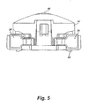
FIG. 5 is a front view of one embodiment of the connecting pod ofFIG. 4 . - Referring to
FIGS. 1-2 , arazor handle 10 includes afirst handle portion 12, and connecting pod 14. Thefirst handle portion 12 includes a first moldedportion 16, a battery-powereddevice 18, a second moldedportion 20, and anauxiliary cavity 22. The connectingpod 14 includes a handle-connectingmember 24 and a razor cartridge-connectingmember 26. - The
first handle portion 12, as mentioned above, includes a first moldedportion 16, a battery-poweteddevice 18, a second moldedportion 20, and anauxiliary cavity 22. In some embodiments, thefirst handle portion 12 may also include acavity 28 for housing a battery 30 (seeFIG. 2 ). The first moldedportion 16 can be formed of a rigid molded material that provides therazor handle 10 with the necessary mechanical strength. For example, thefirst mold portion 16 may be made of Glass Fiber Polypropylene ("GFPP"), which has proven to have desirable density (1.00 g/cm3), tensile strength (87 MPa), and flexural strength (108 MPa), as well as an appropriate hardness (Rockwell Hardness R-scale 111). GFPP supplies a desirable balance of mechanical properties for providing therazor handle 10 with weight, structural stability, as well as an attractive finish. However, the first moldedportion 16 may be made of any suitable material. - Referring to
FIG. 2 , the battery-powereddevice 18 can be any device that provides some additional benefit to the end user. For example, in a preferred embodiment, the battery-powereddevice 18 is a motor that spins aneccentric weight 32. In some embodiments, the battery-powereddevice 18 further includes wiring, switch(es), sensor(s), and/or other additional electronic components. Naturally, the battery-powereddevice 18 is connected to abattery 30. - Referring back to
FIG. 1 , the second moldedportion 20 is injection molded onto the first moldedportion 16, and at least partially encases the battery-powereddevice 18. preferably, especially in embodiments utilizing a motor that spins aneccentric weight 32, the battery-powered 18 device is completely encased within the second moldedportion 20 and the first moldedportion 16. Completely encasing the battery-powereddevice 18 between the second moldedportion 20 and the first moldedportion 16 substantially protects the battery-powereddevice 18 from coming into contact with water and other substances that may affect the operability of thedevice 18. - In some embodiments, the second molded
portion 20 can be formed of thermoplastic rubber ("TPE"), and preferably VYRAM® rubber 9211-35W906 that is commercially available through Advanced Elastomer Systems (AES) of Akron, OH, USA. The TPE material identified above has desirable hardness (45 Shore A), specific gravity (.92), (ultimate) tensile strength (3.0 MPa), (ultimate) elongation (450%). The TPE material also has desirable compressive qualities, which are useful for creating various razor handle features, such as, but not limited to, gripping structures 34 (discussed infra). However, any suitable material known to those of skill in the art can be used in place of the above-identified material. - The second molded
portion 20, as mentioned, may also be utilized to form additional features on thefirst handle portion 12. For example, the second moldedportion 20 may form at least a portion of theauxiliary cavity 22,cavity 28, gripping structures 34 (see e.g.,FIG. 1 ), On/Off buttons 36 for the battery-powered device 18 (see e.g.,FIG. 1 ), and/or pod connecting members 38 (discussed infra). Furthermore, the second moldedportion 20 may be a single, unitary piece, or may be several separate elements, as shown inFIG. 1 . - Referring again to
FIG. 2 , thefirst handle portion 12 can form acavity 28 sized for receiving at least a portion of abattery 30. Thecavity 28 may be formed of the first moldedportion 16 and/or the second moldedportion 20. Using the materials listed above, it is preferable that thecavity 28 be formed primarily of the first moldedportion 16 because of its rigidity and hardness. The GFPP material provides a morestable cavity 28 material that is less likely to undesirably change shape during the life of thefirst handle portion 12 than does the TPE. In some embodiments, thecavity 28 is sized for receiving at least a portion of a standard, AAA-sized battery, as shown in FIG. 6. However, thecavity 28 may also be sized to receive at least a portion of any sizedbattery 30. Preferably, thecavity 28 is oriented within therazor handle 10 such that therazor handle 10 is ergonomically shaped. - Alternatively, and although not shown, a
battery 30 may be entirely encased in, or in between, the first and/or second molded portions of the first handle portion. Such a situation may be especially useful in a disposable-type razor that is intended to be discarded once thebattery 30 has expired. - Referring now to
FIGS. 3-4 , thefirst handle portion 12 includes anauxiliary cavity 22. Theauxiliary cavity 22 can include a pod-connectingmember 38, and is sized and shaped to receive a connectingpod 14. The pod-connectingmember 38 may include, for example, one ormore slots 40 in theauxiliary cavity 22 into which complimentary handle-connecting member(s) 24 (discussed infra) on the connectingpod 14 fit. Alternatively, theauxiliary cavity 22 can be one or more protrusions (not shown) that fit into complimentary slots (not shown) on the connectingpod 14. - The
auxiliary cavity 22 is typically located near oneend 42 of thefirst handle portion 12. Therefore, when the connectingpod 14 is attached, the cartridge-connecting members 26 (discussed infra) on the connectingpod 14, therazor cartridge 44 can be conveniently releasably secured to the razor handle. Theauxiliary cavity 22, naturally, is sized and shaped to receive the connectingpod 14. - Referring now to
FIGS. 3-5 , the connectingpod 14 is typically pre-assembled, and includes a cartridge-connectingmember 26, and a handle-connectingmember 24. In most embodiments, the connectingpod 14 further includes arelease mechanism 46 and a biasingmember 48. The biasingmember 48 is operable to urge therazor cartridge 44 toward a rest position (shown inFIG. 3 ), but is able to allow therazor cartridge 44 to pivot relative to the handle (not shown) when forces are placed on therazor cartridge 44. As shown the biasingmember 48 is a spring-loadedplunger 50; however, any suitable biasingmember 48, such as a leaf spring (not shown) may be utilized. As discussed above, the handle-connectingmember 24 of the connectingpod 14, and the pod-connectingmember 38 of thefirst handle portion 12 cooperate to connect the connectingpod 14 and thefirst handle portion 12. Together, once connected, the connectingpod 14 and thefirst handle portion 12 are typically not intended to be separated during normal use. - The cartridge-connecting
member 26 may any one of numerous types ofcartridge connector members 26 known in the art, and may connect to thecartridge 44 in either a fixed manner, or a pivotal manner. For example, as shown inFIGS. 4 and5 , the cartridge-connectingmember 26 includes at least twojournal bearings 52 which mate withcomplimentary connectors 54 on an associatedrazor cartridge 44. When connected, therazor cartridge 44 can, in some embodiments, pivot relative to the razor handle 10. In addition, and although not shown, an inter-connect member may be attached to therazor cartridge 44 such that therazor cartridge 44 pivots relative to the inter-connect member (and, accordingly, the handle 10). However, in these embodiments, the inter-connect member is fixedly attached in any suitable manner to the connectingpod 14. Therelease button 46 may be of any suitable type. In the embodiment shown, therelease button 46 pivots the cartridge-connectingmembers 26 inward, which, in turn, releases therazor cartridge 44. - As discussed above, the handle-connecting member(s) 24 are complimentary to the pod-connecting member(s) 38 of the
first handle portion 12. The handle-connecting member(s) 24, as noted above, may be any suitable type and may be "male" or "female". - One method for making the razor handle 10 of the present invention includes the following steps. The first molded
portion 16 of afirst handle portion 12 is injection molded. The battery-powereddevice 18 is then secured to,the first moldedportion 12 of thefirst handle portion 12. The second moldedportion 20 of thefirst handle portion 12 is then injection molded such that at least a portion of the battery-powereddevice 18 is encased in the first handle portion 12 (e.g., between the first and second moldedportions 16, 20). The connectingpod 14 is assembled and attached to thefirst handle portion 12 by connecting the pod-connecting member(s) 38 of thefirst handle portion 12 to the handle-connecting member(s) 24 of the connectingpod 14. - In some embodiments, although not shown, the
first handle portion 12 may include additional molded portion(s). The additional portion(s) may be formed at any point in time during before, during or after the two (2) injection molding processes described in the preceding paragraph. - In use, the user couples a
razor cartridge 44 to the cartridge-connecting member(s) 26 of the connectingpod 14, activates the battery-powereddevice 18, and proceeds to shave unwanted hair from a surface. Upon finishing shaving, the user selectively de-activates the battery-powereddevice 18 when the razor handle 10 is not in use. - Modification and variations may be made to the disclosed embodiments without departing from the subject of the invention as defined by the following claims. For example, although not shown, additional measures can be taken to prevent the
first handle portion 12 and the connectingpod 14 from separating. For example, in some instances, a rivet or screw (not shown), may be used to secure the first handle portion and the connecting pod together in addition to, or in place of, the pod-/handle-connecting member(s) 38,24 of thefirst handle portion 12 and connectingpod 14, respectively.
Claims (10)
- A razor handle (10), characterized by:- a connecting pod (14) having a handle-connecting member (24) and a cartridge-connecting member (26), the cartridge-connecting member (26) being operable to connect to a selectively detachable razor cartridge (44); and- a first handle portion (12) having a first molded portion (16) and an auxiliary cavity (22) having a pod-connecting member (38);- wherein the handle-connecting member (24) of the connecting pod (14) is connected to the pod-connecting member (38) in the auxiliary cavity (22) of the first handle portion (12) such that the connecting pod (14) and the first handle portion (12) are not detachable during normal use of the razor handle (10);
characterized in that- the first handle portion (12) further comprises a battery-powered device (18) and a second molded portion (20);- wherein the second molded portion (20) is injection molded onto the first molded portion (16) and at least partially encases the battery-powered device (18); and- wherein the battery powered device (18) is at least partially encased between the first molded portion (16) and the second molded portion (20). - The razor handle (10) of claim 1, wherein the battery-powered device (18) is a motorized spinning eccentric weight (32).
- The razor handle (10) of claim 1 or 2, wherein the connecting pod (14) includes a release mechanism (46) for selectively detaching the razor cartridge (44) from the connecting pod (14).
- The razor handle (10) of any one of claims 1 to 3, wherein the cartridge-connecting member (26) pivotally connects to the selectively detachable razor cartridge (44).
- The razor handle (10) of any one of claims 1 to 4, the first molded portion (16) being formed from a rigid material.
- The razor handle (10) of any one of claims 1 to 5, the battery-powered device (18) being completely encased within the second molded portion (20) and the first molded portion (16).
- The razor handle (10) of any one of claims 1 to 6, the second molded (20) portion being formed of a thermoplastic material.
- The razor handle (10) of any one of claims 1 to 7, wherein the first handle portion (12) includes a cavity (28) sized for receiving at least a portion of a battery (30), the cavity (28) being formed from at least one of the first molded portion (16) and the second molded portion (20).
- The razor handle (10) of any one of claims 1 to 7, wherein at least one of the first molded portion (16) and the second molded portion (20) entirely encases a battery (30).
- The razor handle (10) of any one of claims 1 to 9, wherein the second molded portion (20) forms at least a portion of the auxiliary cavity (22).
Priority Applications (1)
| Application Number | Priority Date | Filing Date | Title |
|---|---|---|---|
| PL09176189T PL2147758T3 (en) | 2005-04-05 | 2006-04-04 | Razor handle |
Applications Claiming Priority (2)
| Application Number | Priority Date | Filing Date | Title |
|---|---|---|---|
| US66882605P | 2005-04-05 | 2005-04-05 | |
| EP06740673A EP1890850B1 (en) | 2005-04-05 | 2006-04-04 | Method for making a handle for a shaving implement |
Related Parent Applications (2)
| Application Number | Title | Priority Date | Filing Date |
|---|---|---|---|
| EP06740673A Division EP1890850B1 (en) | 2005-04-05 | 2006-04-04 | Method for making a handle for a shaving implement |
| EP06740673.6 Division | 2006-04-04 |
Publications (2)
| Publication Number | Publication Date |
|---|---|
| EP2147758A1 EP2147758A1 (en) | 2010-01-27 |
| EP2147758B1 true EP2147758B1 (en) | 2013-09-04 |
Family
ID=36645810
Family Applications (2)
| Application Number | Title | Priority Date | Filing Date |
|---|---|---|---|
| EP06740673A Active EP1890850B1 (en) | 2005-04-05 | 2006-04-04 | Method for making a handle for a shaving implement |
| EP09176189.0A Active EP2147758B1 (en) | 2005-04-05 | 2006-04-04 | Razor handle |
Family Applications Before (1)
| Application Number | Title | Priority Date | Filing Date |
|---|---|---|---|
| EP06740673A Active EP1890850B1 (en) | 2005-04-05 | 2006-04-04 | Method for making a handle for a shaving implement |
Country Status (8)
| Country | Link |
|---|---|
| US (1) | US20060242847A1 (en) |
| EP (2) | EP1890850B1 (en) |
| JP (1) | JP5198252B2 (en) |
| AT (1) | ATE448920T1 (en) |
| AU (1) | AU2006232117B2 (en) |
| DE (1) | DE602006010543D1 (en) |
| PL (2) | PL1890850T3 (en) |
| WO (1) | WO2006108115A1 (en) |
Families Citing this family (32)
| Publication number | Priority date | Publication date | Assignee | Title |
|---|---|---|---|---|
| US20080086899A1 (en) * | 2006-10-12 | 2008-04-17 | Gallagher Richard N | Razor head and method for making the same |
| US20100005669A1 (en) * | 2008-07-14 | 2010-01-14 | Florina Winter | Razor Handle |
| USD615704S1 (en) | 2009-05-21 | 2010-05-11 | American Safety Razor | Shaving razor |
| USD625882S1 (en) | 2009-05-21 | 2010-10-19 | American Safety Razor | Shaving razor |
| USD633252S1 (en) | 2009-11-30 | 2011-02-22 | American Safety Razor | Shaving razor |
| USD640004S1 (en) | 2009-11-30 | 2011-06-14 | American Safety Razor | Shaving razor |
| USD640414S1 (en) | 2009-11-30 | 2011-06-21 | American Safety Razor | Shaving razor |
| USD636533S1 (en) | 2010-05-11 | 2011-04-19 | American Safety Razor | Razor handle |
| USD635718S1 (en) | 2010-05-12 | 2011-04-05 | American Safety Razor | Razor handle |
| USD636938S1 (en) | 2010-05-12 | 2011-04-26 | American Safety Razor | Razor handle |
| US8745883B2 (en) | 2010-09-29 | 2014-06-10 | The Gillette Company | Razor handle with a rotatable portion |
| US8745882B2 (en) | 2010-09-29 | 2014-06-10 | The Gillette Company | Flexible and separable portion of a razor handle |
| US8938885B2 (en) | 2012-05-01 | 2015-01-27 | The Gillette Company | Razor handle with a rotatable portion |
| WO2014094908A1 (en) * | 2012-12-21 | 2014-06-26 | Bic-Violex Sa | Shaver |
| JP6250357B2 (en) * | 2013-10-15 | 2017-12-20 | 株式会社貝印刃物開発センター | Replacement blade removable razor |
| CN109414828B (en) | 2016-03-18 | 2020-12-18 | 个人护理市场及调研公司 | Razor case |
| USD765912S1 (en) | 2016-03-23 | 2016-09-06 | Phan Thi Minh Vinh | Razor handle |
| WO2018007844A1 (en) * | 2016-07-08 | 2018-01-11 | Bic Violex S.A. | Reconfigurable shaving razors |
| US10414058B2 (en) | 2016-08-11 | 2019-09-17 | The Gillette Company Llc | Handle for a razor |
| US11285630B2 (en) | 2016-08-11 | 2022-03-29 | The Gillette Company Llc | Handle for a razor |
| US10940598B2 (en) | 2016-08-11 | 2021-03-09 | The Gillette Company Llc | Handle for a razor |
| US20180043556A1 (en) * | 2016-08-11 | 2018-02-15 | The Gillette Company | Handle for a razor |
| US11130247B2 (en) | 2016-08-11 | 2021-09-28 | The Gillette Company Llc | Handle for a razor |
| US10226874B2 (en) * | 2016-08-11 | 2019-03-12 | The Gillette Company Llc | Handle for a razor |
| US9993931B1 (en) | 2016-11-23 | 2018-06-12 | Personal Care Marketing And Research, Inc. | Razor docking and pivot |
| USD802842S1 (en) | 2017-03-15 | 2017-11-14 | Vu Phan Quang Ngo | Safety razor handle |
| USD815776S1 (en) | 2017-10-08 | 2018-04-17 | Vu Phan Quang Ngo | Safety razor |
| USD884971S1 (en) | 2019-02-27 | 2020-05-19 | Pcmr International Ltd | Razor cartridge |
| USD884969S1 (en) | 2019-02-27 | 2020-05-19 | Pcmr International Ltd | Combined razor cartridge guard and docking |
| USD884970S1 (en) | 2019-02-27 | 2020-05-19 | PCMR International Ltd. | Razor cartridge guard |
| US11000960B1 (en) | 2020-11-16 | 2021-05-11 | Personal Care Marketing And Research, Inc. | Razor exposure |
| WO2022160230A1 (en) * | 2021-01-29 | 2022-08-04 | The Gillette Company Llc | Handle for a razor |
Family Cites Families (13)
| Publication number | Priority date | Publication date | Assignee | Title |
|---|---|---|---|---|
| DE8903182U1 (en) * | 1989-03-15 | 1989-05-03 | Wilkinson Sword Gmbh, 5650 Solingen, De | |
| JP2714462B2 (en) * | 1989-08-19 | 1998-02-16 | 松下電工株式会社 | Vibrating razor |
| GB9208098D0 (en) * | 1992-04-13 | 1992-05-27 | Gillette Co | Razor with movable cartridge |
| US5347717A (en) * | 1993-11-05 | 1994-09-20 | Ts Ai Tse Jen | Chuck assembly for a disposable razor |
| US5544415A (en) * | 1994-12-06 | 1996-08-13 | Kunnex Incorporated | Water-proof and washable electric razor |
| CA2235115A1 (en) * | 1997-06-16 | 1998-12-16 | David C. Coffin | Razor providing pivoting and swivelling razor head support |
| US6749788B1 (en) * | 2000-10-26 | 2004-06-15 | The Gillette Company | Method and apparatus for making a shaving razor handle |
| GB0303872D0 (en) * | 2003-02-19 | 2003-03-26 | Gillette Co | Hand held appliances |
| US7028405B2 (en) * | 2003-03-04 | 2006-04-18 | S.C. Johnson & Son, Inc. | Vibratory shaver |
| US20040216311A1 (en) * | 2003-03-28 | 2004-11-04 | Eveready Battery Company, Inc. | Razor handle assembly |
| US6928738B2 (en) * | 2003-07-18 | 2005-08-16 | Geronimo Segrea | Razor with integral trimming wand |
| EP1563967A1 (en) * | 2004-02-11 | 2005-08-17 | Eveready Battery Company, Inc. | Shaver and method of manufacturing a shaver |
| AU2006232133B2 (en) * | 2005-04-05 | 2012-06-21 | Edgewell Personal Care Brands, Llc | Razor handle and method for making same |
-
2006
- 2006-04-04 EP EP06740673A patent/EP1890850B1/en active Active
- 2006-04-04 US US11/398,263 patent/US20060242847A1/en not_active Abandoned
- 2006-04-04 EP EP09176189.0A patent/EP2147758B1/en active Active
- 2006-04-04 AU AU2006232117A patent/AU2006232117B2/en not_active Ceased
- 2006-04-04 PL PL06740673T patent/PL1890850T3/en unknown
- 2006-04-04 WO PCT/US2006/012936 patent/WO2006108115A1/en active Application Filing
- 2006-04-04 JP JP2008505548A patent/JP5198252B2/en active Active
- 2006-04-04 AT AT06740673T patent/ATE448920T1/en not_active IP Right Cessation
- 2006-04-04 DE DE602006010543T patent/DE602006010543D1/en active Active
- 2006-04-04 PL PL09176189T patent/PL2147758T3/en unknown
Also Published As
| Publication number | Publication date |
|---|---|
| WO2006108115A1 (en) | 2006-10-12 |
| AU2006232117B2 (en) | 2012-07-19 |
| ATE448920T1 (en) | 2009-12-15 |
| JP5198252B2 (en) | 2013-05-15 |
| JP2008534234A (en) | 2008-08-28 |
| PL2147758T3 (en) | 2014-02-28 |
| AU2006232117A1 (en) | 2006-10-12 |
| EP1890850B1 (en) | 2009-11-18 |
| EP1890850A1 (en) | 2008-02-27 |
| PL1890850T3 (en) | 2010-05-31 |
| US20060242847A1 (en) | 2006-11-02 |
| DE602006010543D1 (en) | 2009-12-31 |
| EP2147758A1 (en) | 2010-01-27 |
Similar Documents
| Publication | Publication Date | Title |
|---|---|---|
| EP2147758B1 (en) | Razor handle | |
| EP1888304B1 (en) | Razor handle and method for making same | |
| US4413411A (en) | Razor handle | |
| EP3609660B1 (en) | Razor head converter | |
| EP2830840B1 (en) | Indicia for razor with a rotatable portion | |
| EP1885527B1 (en) | Shaving implement having a moving blade | |
| EP2558250B1 (en) | Shaving cartridge with a biasing member | |
| EP2962815A1 (en) | Shaving razor pivot lock | |
| US20030115762A1 (en) | Razor assembly with replaceable cartridge | |
| US20060260131A1 (en) | Razor cartridge having a decoupled guard bar | |
| EP1308250A1 (en) | Razor assembly with replaceable cartridge | |
| GB2362849A (en) | Unitary spring clip for retaining a razor cartridge on a handle | |
| US20210354323A1 (en) | Razor handle and method of manufacture | |
| AU2012216798A1 (en) | Razor Handle and Method for Making Same | |
| GB2064408A (en) | Razor Handle | |
| US20120192428A1 (en) | Electric Shaver With Moisturizing Bar | |
| CN211440086U (en) | Knife rest structure and shaver | |
| JP2928844B2 (en) | Rotary electric razor | |
| JP2729746B2 (en) | Rotary electric razor | |
| GB2064409A (en) | Razor Blade Assembly |
Legal Events
| Date | Code | Title | Description |
|---|---|---|---|
| PUAI | Public reference made under article 153(3) epc to a published international application that has entered the european phase |
Free format text: ORIGINAL CODE: 0009012 |
|
| AC | Divisional application: reference to earlier application |
Ref document number: 1890850 Country of ref document: EP Kind code of ref document: P |
|
| AK | Designated contracting states |
Kind code of ref document: A1 Designated state(s): AT BE BG CH CY CZ DE DK EE ES FI FR GB GR HU IE IS IT LI LT LU LV MC NL PL PT RO SE SI SK TR |
|
| RIN1 | Information on inventor provided before grant (corrected) |
Inventor name: PFENNIGER, PHILIPP Inventor name: HITCHCOCK, ANDREW Inventor name: PACILIO, JOHN Inventor name: PENNELLA, ANDREW Inventor name: DANSREAU, PAUL |
|
| 17P | Request for examination filed |
Effective date: 20100722 |
|
| 17Q | First examination report despatched |
Effective date: 20110222 |
|
| GRAP | Despatch of communication of intention to grant a patent |
Free format text: ORIGINAL CODE: EPIDOSNIGR1 |
|
| INTG | Intention to grant announced |
Effective date: 20130327 |
|
| RAP1 | Party data changed (applicant data changed or rights of an application transferred) |
Owner name: EVEREADY BATTERY COMPANY, INC. |
|
| RIN1 | Information on inventor provided before grant (corrected) |
Inventor name: PFENNIGER, PHILIPP Inventor name: PENNELLA, ANDREW Inventor name: HITCHCOCK, ANDREW Inventor name: PACILIO, JOHN Inventor name: DANSREAU, PAUL |
|
| GRAS | Grant fee paid |
Free format text: ORIGINAL CODE: EPIDOSNIGR3 |
|
| GRAA | (expected) grant |
Free format text: ORIGINAL CODE: 0009210 |
|
| AC | Divisional application: reference to earlier application |
Ref document number: 1890850 Country of ref document: EP Kind code of ref document: P |
|
| AK | Designated contracting states |
Kind code of ref document: B1 Designated state(s): AT BE BG CH CY CZ DE DK EE ES FI FR GB GR HU IE IS IT LI LT LU LV MC NL PL PT RO SE SI SK TR |
|
| REG | Reference to a national code |
Ref country code: GB Ref legal event code: FG4D |
|
| REG | Reference to a national code |
Ref country code: CH Ref legal event code: EP |
|
| REG | Reference to a national code |
Ref country code: AT Ref legal event code: REF Ref document number: 630224 Country of ref document: AT Kind code of ref document: T Effective date: 20130915 |
|
| REG | Reference to a national code |
Ref country code: IE Ref legal event code: FG4D |
|
| REG | Reference to a national code |
Ref country code: DE Ref legal event code: R096 Ref document number: 602006038304 Country of ref document: DE Effective date: 20131031 |
|
| REG | Reference to a national code |
Ref country code: AT Ref legal event code: MK05 Ref document number: 630224 Country of ref document: AT Kind code of ref document: T Effective date: 20130904 |
|
| REG | Reference to a national code |
Ref country code: NL Ref legal event code: VDEP Effective date: 20130904 |
|
| PG25 | Lapsed in a contracting state [announced via postgrant information from national office to epo] |
Ref country code: LT Free format text: LAPSE BECAUSE OF FAILURE TO SUBMIT A TRANSLATION OF THE DESCRIPTION OR TO PAY THE FEE WITHIN THE PRESCRIBED TIME-LIMIT Effective date: 20130904 Ref country code: SE Free format text: LAPSE BECAUSE OF FAILURE TO SUBMIT A TRANSLATION OF THE DESCRIPTION OR TO PAY THE FEE WITHIN THE PRESCRIBED TIME-LIMIT Effective date: 20130904 Ref country code: CY Free format text: LAPSE BECAUSE OF FAILURE TO SUBMIT A TRANSLATION OF THE DESCRIPTION OR TO PAY THE FEE WITHIN THE PRESCRIBED TIME-LIMIT Effective date: 20130814 Ref country code: AT Free format text: LAPSE BECAUSE OF FAILURE TO SUBMIT A TRANSLATION OF THE DESCRIPTION OR TO PAY THE FEE WITHIN THE PRESCRIBED TIME-LIMIT Effective date: 20130904 |
|
| REG | Reference to a national code |
Ref country code: NL Ref legal event code: VDEP Effective date: 20130904 |
|
| REG | Reference to a national code |
Ref country code: LT Ref legal event code: MG4D |
|
| PG25 | Lapsed in a contracting state [announced via postgrant information from national office to epo] |
Ref country code: FI Free format text: LAPSE BECAUSE OF FAILURE TO SUBMIT A TRANSLATION OF THE DESCRIPTION OR TO PAY THE FEE WITHIN THE PRESCRIBED TIME-LIMIT Effective date: 20130904 Ref country code: GR Free format text: LAPSE BECAUSE OF FAILURE TO SUBMIT A TRANSLATION OF THE DESCRIPTION OR TO PAY THE FEE WITHIN THE PRESCRIBED TIME-LIMIT Effective date: 20131205 Ref country code: LV Free format text: LAPSE BECAUSE OF FAILURE TO SUBMIT A TRANSLATION OF THE DESCRIPTION OR TO PAY THE FEE WITHIN THE PRESCRIBED TIME-LIMIT Effective date: 20130904 Ref country code: SI Free format text: LAPSE BECAUSE OF FAILURE TO SUBMIT A TRANSLATION OF THE DESCRIPTION OR TO PAY THE FEE WITHIN THE PRESCRIBED TIME-LIMIT Effective date: 20130904 |
|
| REG | Reference to a national code |
Ref country code: PL Ref legal event code: T3 |
|
| PG25 | Lapsed in a contracting state [announced via postgrant information from national office to epo] |
Ref country code: BE Free format text: LAPSE BECAUSE OF FAILURE TO SUBMIT A TRANSLATION OF THE DESCRIPTION OR TO PAY THE FEE WITHIN THE PRESCRIBED TIME-LIMIT Effective date: 20130904 Ref country code: CY Free format text: LAPSE BECAUSE OF FAILURE TO SUBMIT A TRANSLATION OF THE DESCRIPTION OR TO PAY THE FEE WITHIN THE PRESCRIBED TIME-LIMIT Effective date: 20130904 |
|
| PG25 | Lapsed in a contracting state [announced via postgrant information from national office to epo] |
Ref country code: NL Free format text: LAPSE BECAUSE OF FAILURE TO SUBMIT A TRANSLATION OF THE DESCRIPTION OR TO PAY THE FEE WITHIN THE PRESCRIBED TIME-LIMIT Effective date: 20130904 Ref country code: RO Free format text: LAPSE BECAUSE OF FAILURE TO SUBMIT A TRANSLATION OF THE DESCRIPTION OR TO PAY THE FEE WITHIN THE PRESCRIBED TIME-LIMIT Effective date: 20130904 Ref country code: EE Free format text: LAPSE BECAUSE OF FAILURE TO SUBMIT A TRANSLATION OF THE DESCRIPTION OR TO PAY THE FEE WITHIN THE PRESCRIBED TIME-LIMIT Effective date: 20130904 Ref country code: SK Free format text: LAPSE BECAUSE OF FAILURE TO SUBMIT A TRANSLATION OF THE DESCRIPTION OR TO PAY THE FEE WITHIN THE PRESCRIBED TIME-LIMIT Effective date: 20130904 Ref country code: IS Free format text: LAPSE BECAUSE OF FAILURE TO SUBMIT A TRANSLATION OF THE DESCRIPTION OR TO PAY THE FEE WITHIN THE PRESCRIBED TIME-LIMIT Effective date: 20140104 Ref country code: CZ Free format text: LAPSE BECAUSE OF FAILURE TO SUBMIT A TRANSLATION OF THE DESCRIPTION OR TO PAY THE FEE WITHIN THE PRESCRIBED TIME-LIMIT Effective date: 20130904 |
|
| PG25 | Lapsed in a contracting state [announced via postgrant information from national office to epo] |
Ref country code: ES Free format text: LAPSE BECAUSE OF FAILURE TO SUBMIT A TRANSLATION OF THE DESCRIPTION OR TO PAY THE FEE WITHIN THE PRESCRIBED TIME-LIMIT Effective date: 20130904 |
|
| REG | Reference to a national code |
Ref country code: DE Ref legal event code: R097 Ref document number: 602006038304 Country of ref document: DE |
|
| PG25 | Lapsed in a contracting state [announced via postgrant information from national office to epo] |
Ref country code: PT Free format text: LAPSE BECAUSE OF FAILURE TO SUBMIT A TRANSLATION OF THE DESCRIPTION OR TO PAY THE FEE WITHIN THE PRESCRIBED TIME-LIMIT Effective date: 20140106 |
|
| PLBE | No opposition filed within time limit |
Free format text: ORIGINAL CODE: 0009261 |
|
| STAA | Information on the status of an ep patent application or granted ep patent |
Free format text: STATUS: NO OPPOSITION FILED WITHIN TIME LIMIT |
|
| 26N | No opposition filed |
Effective date: 20140605 |
|
| PG25 | Lapsed in a contracting state [announced via postgrant information from national office to epo] |
Ref country code: IT Free format text: LAPSE BECAUSE OF FAILURE TO SUBMIT A TRANSLATION OF THE DESCRIPTION OR TO PAY THE FEE WITHIN THE PRESCRIBED TIME-LIMIT Effective date: 20130904 |
|
| REG | Reference to a national code |
Ref country code: DE Ref legal event code: R097 Ref document number: 602006038304 Country of ref document: DE Effective date: 20140605 |
|
| PG25 | Lapsed in a contracting state [announced via postgrant information from national office to epo] |
Ref country code: DK Free format text: LAPSE BECAUSE OF FAILURE TO SUBMIT A TRANSLATION OF THE DESCRIPTION OR TO PAY THE FEE WITHIN THE PRESCRIBED TIME-LIMIT Effective date: 20130904 |
|
| PG25 | Lapsed in a contracting state [announced via postgrant information from national office to epo] |
Ref country code: LU Free format text: LAPSE BECAUSE OF FAILURE TO SUBMIT A TRANSLATION OF THE DESCRIPTION OR TO PAY THE FEE WITHIN THE PRESCRIBED TIME-LIMIT Effective date: 20140404 Ref country code: MC Free format text: LAPSE BECAUSE OF FAILURE TO SUBMIT A TRANSLATION OF THE DESCRIPTION OR TO PAY THE FEE WITHIN THE PRESCRIBED TIME-LIMIT Effective date: 20130904 |
|
| REG | Reference to a national code |
Ref country code: CH Ref legal event code: PL |
|
| REG | Reference to a national code |
Ref country code: IE Ref legal event code: MM4A |
|
| PG25 | Lapsed in a contracting state [announced via postgrant information from national office to epo] |
Ref country code: CH Free format text: LAPSE BECAUSE OF NON-PAYMENT OF DUE FEES Effective date: 20140430 Ref country code: LI Free format text: LAPSE BECAUSE OF NON-PAYMENT OF DUE FEES Effective date: 20140430 |
|
| PG25 | Lapsed in a contracting state [announced via postgrant information from national office to epo] |
Ref country code: IE Free format text: LAPSE BECAUSE OF NON-PAYMENT OF DUE FEES Effective date: 20140404 |
|
| REG | Reference to a national code |
Ref country code: FR Ref legal event code: PLFP Year of fee payment: 11 |
|
| PG25 | Lapsed in a contracting state [announced via postgrant information from national office to epo] |
Ref country code: BG Free format text: LAPSE BECAUSE OF FAILURE TO SUBMIT A TRANSLATION OF THE DESCRIPTION OR TO PAY THE FEE WITHIN THE PRESCRIBED TIME-LIMIT Effective date: 20130904 |
|
| PG25 | Lapsed in a contracting state [announced via postgrant information from national office to epo] |
Ref country code: HU Free format text: LAPSE BECAUSE OF FAILURE TO SUBMIT A TRANSLATION OF THE DESCRIPTION OR TO PAY THE FEE WITHIN THE PRESCRIBED TIME-LIMIT; INVALID AB INITIO Effective date: 20060404 Ref country code: TR Free format text: LAPSE BECAUSE OF FAILURE TO SUBMIT A TRANSLATION OF THE DESCRIPTION OR TO PAY THE FEE WITHIN THE PRESCRIBED TIME-LIMIT Effective date: 20130904 |
|
| REG | Reference to a national code |
Ref country code: FR Ref legal event code: PLFP Year of fee payment: 12 |
|
| REG | Reference to a national code |
Ref country code: FR Ref legal event code: PLFP Year of fee payment: 13 |
|
| PGFP | Annual fee paid to national office [announced via postgrant information from national office to epo] |
Ref country code: FR Payment date: 20200427 Year of fee payment: 15 |
|
| PGFP | Annual fee paid to national office [announced via postgrant information from national office to epo] |
Ref country code: GB Payment date: 20200427 Year of fee payment: 15 |
|
| GBPC | Gb: european patent ceased through non-payment of renewal fee |
Effective date: 20210404 |
|
| PG25 | Lapsed in a contracting state [announced via postgrant information from national office to epo] |
Ref country code: GB Free format text: LAPSE BECAUSE OF NON-PAYMENT OF DUE FEES Effective date: 20210404 Ref country code: FR Free format text: LAPSE BECAUSE OF NON-PAYMENT OF DUE FEES Effective date: 20210430 |
|
| PGFP | Annual fee paid to national office [announced via postgrant information from national office to epo] |
Ref country code: PL Payment date: 20230322 Year of fee payment: 18 |
|
| P01 | Opt-out of the competence of the unified patent court (upc) registered |
Effective date: 20230526 |
|
| PGFP | Annual fee paid to national office [announced via postgrant information from national office to epo] |
Ref country code: DE Payment date: 20230427 Year of fee payment: 18 |