EP2147736A2 - Device for thermal deburring of workpieces - Google Patents
Device for thermal deburring of workpieces Download PDFInfo
- Publication number
- EP2147736A2 EP2147736A2 EP09013550A EP09013550A EP2147736A2 EP 2147736 A2 EP2147736 A2 EP 2147736A2 EP 09013550 A EP09013550 A EP 09013550A EP 09013550 A EP09013550 A EP 09013550A EP 2147736 A2 EP2147736 A2 EP 2147736A2
- Authority
- EP
- European Patent Office
- Prior art keywords
- combustion chamber
- gas mixture
- predetermined
- combustion
- combustible gas
- Prior art date
- Legal status (The legal status is an assumption and is not a legal conclusion. Google has not performed a legal analysis and makes no representation as to the accuracy of the status listed.)
- Granted
Links
Images

Classifications
-
- F—MECHANICAL ENGINEERING; LIGHTING; HEATING; WEAPONS; BLASTING
- F23—COMBUSTION APPARATUS; COMBUSTION PROCESSES
- F23K—FEEDING FUEL TO COMBUSTION APPARATUS
- F23K5/00—Feeding or distributing other fuel to combustion apparatus
- F23K5/02—Liquid fuel
-
- B—PERFORMING OPERATIONS; TRANSPORTING
- B23—MACHINE TOOLS; METAL-WORKING NOT OTHERWISE PROVIDED FOR
- B23D—PLANING; SLOTTING; SHEARING; BROACHING; SAWING; FILING; SCRAPING; LIKE OPERATIONS FOR WORKING METAL BY REMOVING MATERIAL, NOT OTHERWISE PROVIDED FOR
- B23D79/00—Methods, machines, or devices not covered elsewhere, for working metal by removal of material
- B23D79/005—Methods, machines, or devices not covered elsewhere, for working metal by removal of material for thermal deburring
-
- F—MECHANICAL ENGINEERING; LIGHTING; HEATING; WEAPONS; BLASTING
- F23—COMBUSTION APPARATUS; COMBUSTION PROCESSES
- F23D—BURNERS
- F23D14/00—Burners for combustion of a gas, e.g. of a gas stored under pressure as a liquid
- F23D14/46—Details, e.g. noise reduction means
Definitions
- the present invention relates to a device for the thermal deburring of workpieces in a combustion chamber by means of a combustible gas mixture and a method for their operation.
- the workpieces to be deburred are accommodated in a combustion chamber.
- a combustible gas mixture is introduced, for example an ignitable mixture of methane gas and oxygen.
- the mixing of the gas components is usually carried out in a so-called mixing block, which is upstream of the combustion chamber.
- To initiate the gas mixture is a Gaszu 1500kanal, the usual way opens directly into the combustion chamber.
- the gas mixture is ignited by a spark plug located in the mixing block.
- the flame front proceeds from the ignition point in the ignition channel of the mixing block via the gas supply channel into the combustion chamber and ignites the gas mixture present in it. The process takes place within a few milliseconds.
- devices for treating a workpiece under a high pressure regularly have a processing chamber comprising a kind of bell and a closing plate which closes an opening of the bell at a predetermined closing pressure.
- the chamber is connected to a supply channel for supplying a fluid (liquid, gas, etc.) with a loading pressure and the closing structure.
- the locking plate is pressed during machining with a lock cylinder against the opening of the bell.
- About the closing or clamping force is determined in which conditions the chamber is opened if necessary, for example, if a destruction of the pressure vessel is to be feared by excessive loading pressures or the resulting Expionsions latern and thus endangering the environment. This clamping force is kept constant for many plant types.
- the counterforce that results from the machining of the workpiece is dependent on the cross section of the chamber or the bell, so that just for round shapes of the chamber or round openings, which are closed with the locking plate, simplified is placed on the diameter thereof.
- This counterforce is quadratically dependent on the chamber diameter; so that with increasing chamber diameter of the max. permissible loading pressure drops.
- This means with regard to the thermal deburring for example, that combustion chambers with a large combustion chamber diameter are regularly unsuitable for deburring small bores on workpieces, since the high energy required for this purpose per unit cross-sectional area of the combustion chamber can no longer be achieved. So far for such treatments of a workpiece under high pressure, separate devices each having a different chamber diameter and / or a different locking constructions are used.
- a device and a method are to be specified, so that the operation of a device for thermal deburring with high flexibility and efficiency is possible.
- a very safe method for operating such a device should be specified.
- the device for the thermal deburring of workpieces in a combustion chamber by means of a combustible gas mixture is characterized in that an apparatus for operating a plurality of combustion chambers with a different combustion chamber diameter and means for controlling a supply of the gas mixture toward each a predetermined combustion chamber are provided.
- combustion chamber diameter is to be regarded as a generic term for an expansion of the relevant for the machining and / or closing pressures cross-sectional area of the combustion chamber.
- combustion chamber diameter is to be regarded as a generic term for an expansion of the relevant for the machining and / or closing pressures cross-sectional area of the combustion chamber.
- Preference is given to the embodiment in which at least 2, in particular 3 or even 4, combustion chambers with different combustion chamber diameter are operable.
- the number of combustion chambers can be selected, for example, taking into account the workpieces to be processed and / or the different combustible gas mixtures.
- the flexibility is increased in that smaller combustion chambers are used when small workpieces with high loading pressure must be processed, such as deburring small holes on the workpiece.
- the provision of a combustion chamber with a small combustion chamber diameter has the consequence that less of the combustible gas mixture is required, so that not only a better machining result is achieved, but at the same time less costs arise with regard to the deburring process.
- the corresponding means are provided for controlling a supply of the gas mixture toward each of a predetermined combustion chamber.
- These means ensure a redundant and confusion-proof control, so that, for example, predetermined amounts or pressures of the combustible gas mixture are supplied only in the respectively suitable combustion chamber.
- these means for controlling depending on the used to be used combustion chamber clearly selects or provides the components of the device to be used or the pressures of the combustible gas mixture.
- These means for controlling a supply of the gas mixture comprise in particular sensors, valves, electronic controls, and / or emergency switches.
- these means also comprise identification means for uniquely determining the combustion chambers and pressure generating means for providing a predetermined pressure of the gas mixture in the predetermined combustion chamber.
- identification means for example, switches for identifying the combustion chamber, sensors, or the like may be present.
- a predetermined pressure in particular, a “maximum allowable” loading pressure pending from the predetermined combustion chamber is meant, wherein preferably various loading pressures are adjustable up to this maximum loading pressure.
- identification means preferably cooperate with a part of the combustion chamber, for example with its closing bell, closing plate, lock cylinder or the like.
- means for detecting the outer shape or of detection means may also be provided on the combustion chambers, which interact with the identification means.
- the information obtained with the identification means are now coordinated with the operation of the pressure generating means, so that, for example, the predetermined for the identified combustion chamber processing parameters are set.
- a secure, redundant detection could e.g. very simply by querying the nature of the seal groove (e.g., its diameter) in the lock plate. This could be checked before the actual processing, wherein the redundant signal is supplied to the identification means, which then selectively influence the means for controlling the supply of the gas mixture. Especially with systems already in operation, this can represent a cost-effective variant for retrofitting.
- the device has an exchange arrangement for a plurality of combustion chambers with a different combustion chamber diameter, which interacts with identification means for the unambiguous determination of the combustion chambers.
- Such an exchange arrangement allows different combustion chambers to be positioned at approximately the same location of the device.
- the exchange process preferably partially or even be carried out fully automatically.
- the information regarding the combustion chamber used be forwarded to the identification means.
- a metering unit for the components of the combustible gas mixture is provided, which can assume different operating states as a function of the predetermined combustion chamber.
- the dosing unit which is advantageously part of the pressure generating means for providing the predetermined pressure of the combustible gas mixture, has a certain number of modes, which are predetermined in dependence of the identified combustion chamber. This ensures that the identified combustion chamber is operated only with the appropriate loading pressures.
- a single ignition channel or a single mixing block is sufficient, since the components downstream of the dosing unit can be used up to the combustion chamber, regardless of the combustion chamber used.
- the technical complexity in the production and maintenance is significantly reduced.
- the metering unit can be operated with a hydraulic fluid and the hydraulic fluid can be provided as a function of the predetermined combustion chamber.
- the metering unit comprises a cylinder-piston unit, wherein the piston is operated via the hydraulic fluid.
- predetermined pressure states, displacement paths and the like can thus be set redundantly and confusion-proof in the dosing unit.
- the hereby portioned or pressurized components of the combustible gas mixture are thus forwarded in the desired quantitative and qualitative composition to the mixing block or finally the predetermined combustion chamber.
- the dosing unit is provided with some kind of indirect pressure control, i. that the force is limited by the safety valve in the respective hydraulic supply line of the metering unit, with which this pushes the gas into the combustion chamber and thus indirectly the max. possible loading pressure of the combustion chamber is limited.
- the setting of the respective work area for the workpieces can be realized either automatically via a machining program in the controller or manually by adjusting the stroke length of the metering cylinder.
- the hydraulic fluid can be supplied via a plurality of supply lines, each with a directional control valve to a common dosing unit, and the directional control valves cooperate with an identification means for unambiguous determination of the combustion chambers, that only a predetermined supply line is open during operation of the device ,
- a supply line for the hydraulic fluid of the common metering unit is provided for each combustion chamber to be operated.
- exactly one of these supply lines of the hydraulic fluid is activated while the others are locked.
- hydraulically operating directional control valves are preferably used, which are each assigned to a supply line. These directional valves are switched redundant and unmistakable depending on the information obtained by the identification means. By means of these directional valves, the hydraulic flow is controlled, so that so that the desired operating state of the common metering unit is set for the currently used combustion chamber.
- each safety valve for loading pressure control.
- Each safety valve is adapted to the conditions in the given supply line.
- the method according to the invention is particularly preferably used on a device as described here according to the invention.
- the identification of the combustion chamber can be carried out automatically, for example by means of mechanical switches, magnetic, electrical or optical sensors or the like.
- the combustion chambers (bell, closing plate, etc.) advantageously have a unique identification feature which can be evaluated by suitable identification means in a redundant and confusion-proof manner.
- the operating states of the dosing unit are now advantageously set fully automatically.
- the operating state of the dosing unit is characterized in particular by its maximum permissible loading pressure.
- the dosing unit is thus able to provide a loading pressure depending on the identified combustion chamber up to the respective maximum permissible loading pressure available.
- a gas mixture with the desired loading pressure (the maximum of the maximum loading pressure). This gas mixture is introduced via the mixing block in the Entgratungshunt or combustion chamber. After the dosage, the supply lines are closed. The ignition of the gas mixture takes place for example by a mounted in the ignition channel of the mixing block spark plug.
- heat (00 ° C to 3300 ° C) is briefly generated in the combustion chamber to which the workpieces stored therein are exposed. Heat dissipation in the workpiece takes place from outside to inside. If a cross-section on the workpiece, which has a very large area relative to its volume of material, is incapable of dissipating the accumulated energy into the interior of the component (for example a burr), this cross-section is heated to the ignition temperature and oxidized by the oxygen.
- the method is advantageous in particular also because, for example, depending on the workpiece to be used, a selection of the suitable combustion chamber can be made from a plurality of available combustion chambers. This takes place, for example, taking into account the operating parameters of the combustion chamber which are suitable for this workpiece and / or the economical use of the combustible gas mixture.
- the method is particularly advantageous when the combustible gas mixture is provided as a function of the identified combustion chamber with a predetermined maximum charge pressure. This means in particular that preferably the same combustible gas mixture is used, but with a maximum loading pressure adapted to the identified combustion chamber.
- the device is developed such that means for unambiguous closing force limitation are provided as a function of the identified combustion chamber with the corresponding combustion chamber diameter.
- This offers, for example, the advantage that two states of force could be changed at the same time, that is, with one identification signal, the operating state could the dosing unit and a corresponding operating state of the locking system are set redundant. This can ensure that the closing plate opens safely at a maximum pressure load predetermined for the combustion chamber.
- an apparatus for treating a workpiece under a pressure of at least 200 bar comprising a chamber having a chamber diameter, the chamber having a supply channel for supplying a fluid having a loading pressure and a closing plate which is provided with a closing pressure closing an opening of the chamber is connectable, in which an apparatus for operating a plurality of chambers with a different chamber diameter and means are provided for controlling a supply of the fluid toward each of a predetermined chamber.
- Such a device is preferably designed with corresponding features with regard to the embodiments of the supply lines for the hydraulic fluid, the identification means or their possibilities of engagement with the respective supply lines of the hydraulic fluid and / or the configuration of the dosing unit.
- Fig. 1 illustrates a possible structure for a device 1 for the thermal deburring of workpieces.
- the device 1 comprises an arrangement 6, in which a first combustion chamber 3 with a first combustion chamber diameter 7 is positioned together with the corresponding closing plate 26 and the lock cylinder 27.
- the closing plate 26 acts together with a corresponding opening 33 of the combustion chamber 3 or the so-called bell.
- This first combustion chamber 3 with the corresponding first combustion chamber diameter 7 is particularly suitable for the machining of the workpiece 2 shown inside the first combustion chamber 3.
- the oxygen supply 22 and the fuel gas supply 23 are activated by means of the control unit 25, so that these components of the combustible gas mixture 5 are fed via the mixing block 24 into the interior of the first combustion chamber 3.
- the closed during the machining operation by means of the closing plate 26 first combustion chamber 3 then contains the desired quality and quantity of the combustible gas mixture 5, which is ignited by means provided in the mixing block 24 spark plug (not shown here).
- an exchange arrangement 11 is provided in this apparatus 1 for thermal deburring, the exchange of the first combustion chamber 3 by a second combustion chamber 4 with a (from the first Combustion chamber diameter 7 different) second combustion chamber diameter 8 allows.
- this device 1 can be embodied with further combustion chambers and / or replacement arrangements, wherein the replacement arrangement can optionally also be operated manually, since ultimately identification means 9 are also provided for identifying the combustion chamber used.
- the identification means 9 are connected via connections 30, for example to the arrangement 6 or the exchange arrangement 11. The information obtained in the query regarding the combustion chamber to be used is finally forwarded to the control unit 25.
- the identification should take place before the actual machining of the workpiece, so that the cycle time is not increased. Therefore, it is preferred that the identification means cooperate with a detection station upstream of the actual processing station, so that the dosing unit can already be prepared when the combustion chambers are still being replaced.
- a detection station upstream of the actual processing station so that the dosing unit can already be prepared when the combustion chambers are still being replaced.
- combustion chambers with the following combustion chamber diameters are preferred: 120 mm, 150 mm, 170 mm, 200 mm, 250 mm, 320 mm.
- the device has at least 2, 3 or even 4 such combustion chambers.
- maximum loading pressures of approximately 16 bar, 23 bar, 25 bar and / or even 40 bar can be achieved by means of a corresponding control unit or metering unit.
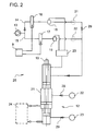
- Fig. 2 now illustrates a particularly preferred embodiment of the in Fig. 1 indicated control unit 25, which comprises the means for controlling a supply of the gas mixture 5 to the respective predetermined combustion chamber.
- first directional control valve 16 or a second directional control valve 17 these diverter valves being part of separate first supply lines 14 and second supply lines 15 for a hydraulic fluid 13 for operating a common metering unit 12 for the components of the combustible gas mixture , Depending on the identified combustion chambers, therefore, either the first supply line 14 or the second supply line 15 are opened by the identification means 9. As can be seen with reference to the illustrated flow direction arrows 29, only the first supply line 14 is opened in the embodiment variant shown here.
- the first supply line 14 has a first directional control valve 16 for providing a desired pressure or a desired quantity of hydraulic fluid 13. Part of this first supply line 14 is also a first safety valve 18 which implements a charge pressure limitation with respect to a first combustion chamber 3. In addition, the first supply line 14 may also be additionally provided with a first check valve 31.
- the second supply line 15 is constructed substantially the same, that includes a second directional control valve 17 and a second safety valve 19 and possibly a second check valve 32.
- the components in the second supply line 15 are tuned to the wastegate or the combustion chamber diameter of the second combustion chamber 4 ,
- the dosage of the oxygen supply 22 and Fuel gas supply 23 causes.
- the required for the Entgratungsvorgang portions of oxygen and fuel gas are generated by means of the illustrated gas cylinder 21 and finally fed to the mixing block 24. From there, the introduction of the gas mixture takes place in the provided combustion chamber, so that then the Entgratungsvorgang can be initiated.
Abstract
Description
Die vorliegende Erfindung betrifft eine Vorrichtung zum thermischen Entgraten von Werkstücken in einer Brennkammer mittels eines brennbaren Gasgemisches sowie ein Verfahren zu deren Betrieb.The present invention relates to a device for the thermal deburring of workpieces in a combustion chamber by means of a combustible gas mixture and a method for their operation.
Bei thermischen Entgratungsanlagen werden die zu entgratenden Werkstücke in einer Brennkammer untergebracht. Nach Verschließen der Brennkammer wird ein brennbares Gasgemisch eingeleitet, beispielsweise eine zündfähige Mischung aus Methangas und Sauerstoff. Die Vermischung der Gaskomponenten erfolgt üblicherweise in einem so genannten Mischblock, der der Brennkammer vorgelagert ist. Zur Einleitung des Gasgemisch dient ein Gaszuführkanal, der üblicher Weise unmittelbar in die Brennkammer mündet. Das Gasgemisch wird durch eine im Mischblock befindliche Zündkerze entzündet. Die Flammenfront schreitet von der Zündstelle im Zündkanal des Mischblocks über den Gaszuführkanal in die Brennkammer und entzündet das in ihm befindliche Gasgemisch. Der Vorgang läuft innerhalb weniger Millisekunden ab. Durch die frei werdende Wärme treten in der Brennkammer kurzzeitig Temperaturen von bis zu 3.500° C auf. Nach dem Zünden des Gasgemischs kommt es aufgrund einer isochoren Reaktion zu einem Druckanstieg in der Brennkammer, welcher von dem Beladedruck der Brennkammer und dem Energieinhalt des Gasgemisches abhängig ist. Dabei können kurz nach dem Zünden des Gasgemisches im Brennraum aufgrund der Explosion Drücke in der Größenordnung von bis zu 1.000 bar entstehen..Durch den resultierenden Hitzeschock, dem die Werkstücke dadurch ausgesetzt sind, werden insbesondere deren Ecken und Kanten abgetragen, da diese Stellen bei großer Oberfläche und kleinem Volumen besonders viel Wärme aufnehmen und somit oxidiert bzw. verbrannt werden. Beim thermischen Entgraten wird mittels der Qualität (z.B. das Mischungsverhältnis) und der Quantität (z.B. der Beladedruck) des Gasgemisch das zu erzielende Bearbeitungsergebnis hinsichtlich des Werkstücks beeinflusst. Auf diese Weise ist eine gründliche und wirtschaftliche Entgratung solcher Werkstücke möglich, ohne dass ein teures Spezialwerkzeug eingesetzt oder eine langwierige Nachbearbeitung von Hand vorgenommen werden muss.In thermal deburring plants, the workpieces to be deburred are accommodated in a combustion chamber. After closing the combustion chamber, a combustible gas mixture is introduced, for example an ignitable mixture of methane gas and oxygen. The mixing of the gas components is usually carried out in a so-called mixing block, which is upstream of the combustion chamber. To initiate the gas mixture is a Gaszuführkanal, the usual way opens directly into the combustion chamber. The gas mixture is ignited by a spark plug located in the mixing block. The flame front proceeds from the ignition point in the ignition channel of the mixing block via the gas supply channel into the combustion chamber and ignites the gas mixture present in it. The process takes place within a few milliseconds. Due to the released heat occur in the combustion chamber for a short time temperatures of up to 3,500 ° C. After ignition of the gas mixture due to an isochoric reaction, there is a pressure increase in the combustion chamber, which is dependent on the loading pressure of the combustion chamber and the energy content of the gas mixture. In this case, shortly after the ignition of the gas mixture in the combustion chamber due to the explosion pressures in the order of up to 1,000 bar incurred. Due to the resulting heat shock to which the workpieces are exposed, in particular their corners and edges are removed, since these places at large Surface and small volume absorb a lot of heat and thus oxidized or burned. In the case of thermal deburring, the quality of the mixture (eg the mixing ratio) and the quantity (eg the loading pressure) of the gas mixture influence the machining result to be achieved with regard to the workpiece. In this way, a thorough and economical deburring of such Workpieces possible without having to use an expensive special tool or a lengthy post-processing by hand must be made.
Es ist bekannt, dass besonders gute und gleich bleibende Ergebnisse hinsichtlich des Entgratens nur realisiert werden können, wenn in der Brennkammer die richtige Zusammensetzung des brennbaren Gasgemisches mit einem vorbestimmten Beladedruck vorliegt. Dies führt dazu, dass zum Teil beachtliche technische Vorbereitungen unternommen werden müssen, um die Vorrichtung zum thermischen Entgraten für unterschiedliche Werkstücke vorzubereiten.It is known that particularly good and consistent results in terms of deburring can only be realized if the correct composition of the combustible gas mixture with a predetermined loading pressure is present in the combustion chamber. As a result, some considerable technical preparations have to be made in order to prepare the thermal deburring device for different workpieces.
Allgemein weisen Vorrichtungen zur Behandlung eines Werkstücks unter einem hohen Druck (von beispielsweise über 200 bar) regelmäßig eine Bearbeitungskammer auf, die eine Art Glocke und einen Schließteller, der mit einem vorgegebenen Schließdruck eine Öffnung der Glocke verschließt, umfasst. Die Kammer ist mit einem Zuführkanal zur Zufuhr eines Fluides (Flüssigkeit, Gas, etc.) mit einem Beladedruck und der Schließkonstruktion verbunden. Der Schließteller wird während der Bearbeitung mit einem Schließzylinder gegen die Öffnung der Glocke gedrückt. Über die Schließ- bzw. Zuhaltekraft wird festgelegt, bei welchen Bedingungen die Kammer notfalls geöffnet wird, z.B. wenn eine Zerstörung des Druckbehälters durch zu hohe Beladedrücke bzw. den daraus resultierenden Expiosionskräften und damit eine Gefährdung der Umwelt zu befürchten ist. Diese Zuhaltekraft wird bei vielen Anlagentypen konstant gehalten. Die Gegenkraft, die aus der Bearbeitung des Werkstücks resultiert, ist abhängig von dem Querschnitt der Kammer bzw. der Glocke, so dass gerade bei runden Formen der Kammer bzw. runden Öffnungen, die mit dem Schließteller verschlossen werden, vereinfacht auf deren Durchmesser abgestellt wird. Diese Gegenkraft ist quadratisch von dem Kammerdurchmesser abhängig; so dass mit größer werdendem Kammerdurchmesser der max. zulässigen Beladedruck sinkt. Das bedeutet mit Hinblick auf das thermische Entgraten beispielsweise, dass Brennkammern mit einem großen Brennkammerdurchmesser regelmäßig ungeeignet sind, kleine Bohrungen an Werkstücken zu entgraten, da die hierfür erforderliche hohe Energie pro Einheitsquerschnittsfläche der Brennkammer nicht mehr erreicht werden kann. Bislang werden für derartige Behandlungen eines Werkstücks unter hohem Druck jeweils separate Vorrichtungen mit jeweils einen anderen Kammerdurchmesser und/oder eine andere Schließkonstruktionen eingesetzt.In general, devices for treating a workpiece under a high pressure (of, for example, over 200 bar) regularly have a processing chamber comprising a kind of bell and a closing plate which closes an opening of the bell at a predetermined closing pressure. The chamber is connected to a supply channel for supplying a fluid (liquid, gas, etc.) with a loading pressure and the closing structure. The locking plate is pressed during machining with a lock cylinder against the opening of the bell. About the closing or clamping force is determined in which conditions the chamber is opened if necessary, for example, if a destruction of the pressure vessel is to be feared by excessive loading pressures or the resulting Expionsionskräften and thus endangering the environment. This clamping force is kept constant for many plant types. The counterforce that results from the machining of the workpiece is dependent on the cross section of the chamber or the bell, so that just for round shapes of the chamber or round openings, which are closed with the locking plate, simplified is placed on the diameter thereof. This counterforce is quadratically dependent on the chamber diameter; so that with increasing chamber diameter of the max. permissible loading pressure drops. This means with regard to the thermal deburring, for example, that combustion chambers with a large combustion chamber diameter are regularly unsuitable for deburring small bores on workpieces, since the high energy required for this purpose per unit cross-sectional area of the combustion chamber can no longer be achieved. So far For such treatments of a workpiece under high pressure, separate devices each having a different chamber diameter and / or a different locking constructions are used.
Hiervon ausgehend ist es Aufgabe der vorliegenden Erfindung, eine Vorrichtung und ein Verfahren anzugeben, dass die mit Bezug auf den Stand der Technik geschilderten technischen Probleme zumindest teilweise lösen. Insbesondere sollen eine Vorrichtung und ein Verfahren angegeben werden, so dass der Betrieb einer Vorrichtung zum thermischen Entgraten mit hoher Flexibilität und Wirtschaftlichkeit möglich ist. Darüber hinaus soll auch ein sehr sicheres Verfahren zum Betrieb einer solchen Vorrichtung angegeben werden.On this basis, it is an object of the present invention to provide an apparatus and a method that at least partially solve the technical problems described with reference to the prior art. In particular, a device and a method are to be specified, so that the operation of a device for thermal deburring with high flexibility and efficiency is possible. In addition, a very safe method for operating such a device should be specified.
Diese Aufgaben werden gelöst mit Vorrichtungen gemäß den Merkmalen der Patentanspruche 1 und 10 sowie einem Verfahren zum Betreiben einer Vorrichtung zum thermischen Entgraten gemäß den Merkmalen des Patentanspruchs 8. Weitere vorteilhaft Ausgestaltungen sind in den jeweils abhängig formulierten Patentansprüchen angeben. Es ist darauf hinzuweisen, dass die in den Patentansprüchen einzeln aufgeführten Merkmale in beliebiger, technologisch sinnvoller, Weise miteinander kombiniert werden können und weitere Ausgestaltungen der Erfindung aufzeigen.These objects are achieved with devices according to the features of
Die Vorrichtung zum thermischen Entgraten von Werkstücken in einer Brennkammer mittels eines brennbaren Gasgemisches zeichnet sich dadurch aus, dass eine Apparatur zum Betrieb mehrerer Brennkammern mit einem unterschiedlichen Brennkammerdurchmesser und Mittel zur Steuerung einer Zufuhr des Gasgemisches hin zu jeweils einer vorbestimmten Brennkammer vorgesehen sind.The device for the thermal deburring of workpieces in a combustion chamber by means of a combustible gas mixture is characterized in that an apparatus for operating a plurality of combustion chambers with a different combustion chamber diameter and means for controlling a supply of the gas mixture toward each a predetermined combustion chamber are provided.
Demgemäß löst sich die Erfindung erstmalig von der Vorstellung, dass eine solche Vorrichtung jeweils mit einer einzelnen Brennkammer zu betreiben ist. Im Gegensatz zum Stand der Technik wir hier vorgeschlagen, eine Apparatur zum Betreiben mehrerer Brennkammern mit einem unterschiedlichen Brennkammerdurchmesser vorzusehen. Klarstellend sei hier darauf hingewiesen, dass der "Brennkammerdurchmesser" als Oberbegriff für eine Ausdehnung der für die Bearbeitung- und/oder Schließdrücke maßgeblichen Querschnittsfläche der Brennkammer anzusehen ist. Bevorzugt ist dabei die Ausgestaltung, bei der zumindest 2, insbesondere 3 oder sogar 4, Brennkammern mit unterschiedlichen Brennkammerdurchmesser betreibbar sind. Die Anzahl der Brennkammern kann beispielsweise unter Berücksichtigung der zu bearbeitenden Werkstücke und/oder der unterschiedlichen brennbaren Gasgemische ausgewählt werden. So wird beispielsweise die Flexibilität in der Weise erhöht, dass kleinere Brennkammern dann eingesetzt werden, wenn kleine Werkstücke mit hohem Beladedruck bearbeitet werden müssen, wie z.B. beim Entgraten kleiner Bohrungen am Werkstück. Die Bereitstellung einer Brennkammer mit kleinem Brennkammerdurchmesser hat zur Folge, dass weniger des brennbaren Gasgemischs benötigt wird, so dass nicht ein nur besseres Bearbeitungsergebnis erzielt wird, sondern gleichzeitig weniger Kosten im Hinblick auf das Entgratungsverfahren entstehen. Dahingegen kann auf eine andere Brennkammer mit einem größeren Brennkammerdurchmesser dann zurückgegriffen werden, wenn beispielsweise Grate an großvolumigen Druckgussteilen zu beseitigen sind oder die quantitive Ausnutzung der Anlage zur Reduzierung der Herstellkosten pro Werkstück gesteigert werden soll.Accordingly, the invention solves for the first time on the idea that such a device is to operate each with a single combustion chamber. In contrast to the prior art, we proposed here to provide an apparatus for operating a plurality of combustion chambers with a different combustion chamber diameter. Clarification should be noted here that the "Combustion chamber diameter" is to be regarded as a generic term for an expansion of the relevant for the machining and / or closing pressures cross-sectional area of the combustion chamber. Preference is given to the embodiment in which at least 2, in particular 3 or even 4, combustion chambers with different combustion chamber diameter are operable. The number of combustion chambers can be selected, for example, taking into account the workpieces to be processed and / or the different combustible gas mixtures. For example, the flexibility is increased in that smaller combustion chambers are used when small workpieces with high loading pressure must be processed, such as deburring small holes on the workpiece. The provision of a combustion chamber with a small combustion chamber diameter has the consequence that less of the combustible gas mixture is required, so that not only a better machining result is achieved, but at the same time less costs arise with regard to the deburring process. On the other hand, it is possible to resort to another combustion chamber with a larger combustion chamber diameter if, for example, burrs on large-volume die-cast parts are to be eliminated or if the quantitative utilization of the installation is to be increased in order to reduce the production costs per workpiece.
Beachtenswert in diesem Zusammenhang ist, das entsprechende Mittel zur Steuerung einer Zufuhr des Gasgemischs hin zu jeweils einer vorbestimmten Brennkammer vorgesehen sind. Diese Mittel gewährleisten eine redundante und verwechslungssichere Steuerung, so dass beispielsweise vorbestimmte Mengen bzw. Drücke des brennbaren Gasgemischs nur in die jeweils dafür geeignete Brennkammer zugeführt werden. Das bedeutet unter anderem, dass diese Mittel zur Steuerung in Abhängigkeit der zum Einsatz gelangenden Brennkammer eindeutig die zu verwendenden Bestandteile der Vorrichtung bzw. die Drücke des brennbaren Gasgemisches auswählt bzw. bereitstellt. Diese Mittel zur Steuerung einer Zufuhr des Gasgemisches umfassen insbesondere Sensoren, Ventile, elektronische Steuerungen, und/oder Notschalter.It is noteworthy in this context that the corresponding means are provided for controlling a supply of the gas mixture toward each of a predetermined combustion chamber. These means ensure a redundant and confusion-proof control, so that, for example, predetermined amounts or pressures of the combustible gas mixture are supplied only in the respectively suitable combustion chamber. This means, inter alia, that these means for controlling depending on the used to be used combustion chamber clearly selects or provides the components of the device to be used or the pressures of the combustible gas mixture. These means for controlling a supply of the gas mixture comprise in particular sensors, valves, electronic controls, and / or emergency switches.
Gemäß einer vorteilhaften Weiterbildung der Vorrichtung umfassen diese Mittel auch Identifikationsmittel zur eindeutigen Bestimmung der Brennkammern und Druckerzeugungsmittel zur Bereitstellung eines vorbestimmten Drucks des Gasgemisches in der vorbestimmten Brennkammer. Im Rahmen der Identifikationsmittel können beispielsweise Schalter zur Identifikation der Brennkammer, Sensoren, oder ähnliches vorhanden sein. Mit einem "vorbestimmten" Druck ist insbesondere ein von der vorbestimmten Brennkammer anhängiger "maximal zulässiger" Beladedruck gemeint, wobei bevorzugt diverse Beladedrücke bis hin zu diesem maximalen Beladedruck einstellbar sind.According to an advantageous development of the device, these means also comprise identification means for uniquely determining the combustion chambers and pressure generating means for providing a predetermined pressure of the gas mixture in the predetermined combustion chamber. As part of the identification means, for example, switches for identifying the combustion chamber, sensors, or the like may be present. By a "predetermined" pressure, in particular, a "maximum allowable" loading pressure pending from the predetermined combustion chamber is meant, wherein preferably various loading pressures are adjustable up to this maximum loading pressure.
Diese Identifikationsmittel wirken bevorzugt mit einem Teil der Brennkammer zusammen, beispielsweise mit deren Schließglocke, Schließteller, Schließzylinder oder dergleichen. Insbesondere können auch Mittel zur Erkennung der äußeren Gestalt bzw. von Erkennungsmitteln an den Brennkammern vorgesehen sein, die mit den Identifikationsmitteln zusammenwirken. Die mit den Identifikationsmitteln erhaltenen Informationen werden nun mit dem Betrieb der Druckerzeugungsmittel koordiniert, so dass beispielsweise die für die identifizierte Brennkammer vorgegebenen Bearbeitungsparameter eingestellt werden. Eine sichere, redundante Erkennung könnte z.B. sehr einfach über das Abfragen der Art der Dichtnut (z.B. deren Durchmesser) im Schließteller stattfinden. Diese könnte vor der eigentlichen Bearbeitung überprüft werden, wobei das redundante Signal den Identifikationsmitteln zugeführt wird, welche dann die Mittel zur Steuerung der Zufuhr des Gasgemisches gezielt beeinflussen. Speziell bei schon in Betrieb befindenden Anlagen kann dies eine kostengünstige Variante zur Nachrüstung darstellen.These identification means preferably cooperate with a part of the combustion chamber, for example with its closing bell, closing plate, lock cylinder or the like. In particular, means for detecting the outer shape or of detection means may also be provided on the combustion chambers, which interact with the identification means. The information obtained with the identification means are now coordinated with the operation of the pressure generating means, so that, for example, the predetermined for the identified combustion chamber processing parameters are set. A secure, redundant detection could e.g. very simply by querying the nature of the seal groove (e.g., its diameter) in the lock plate. This could be checked before the actual processing, wherein the redundant signal is supplied to the identification means, which then selectively influence the means for controlling the supply of the gas mixture. Especially with systems already in operation, this can represent a cost-effective variant for retrofitting.
Besonders vorteilhaft ist es, wenn die Vorrichtung eine Austauschanordnung für eine Mehrzahl von Brennkammern mit einem unterschiedlichen Brennkammerdurchmesser hat, die mit Identifikationsmitteln zur eindeutigen Bestimmung der Brennkammern zusammenwirkt. Eine solche Austauschanordnung ermöglicht, dass in etwa an derselben Stelle der Vorrichtung unterschiedliche Brennkammern positioniert werden können. Dabei kann der Austauschvorgang bevorzugt teil-oder sogar vollautomatisch durchgeführt werden. In diesem Zusammenhang wird zusätzlich auch vorgeschlagen, dass (beispielsweise bei einer vollautomatischen Äustauschvorrichtung) die Informationen hinsichtlich der eingesetzten Brennkammer an die Identifikationsmittel weitergegeben werden.It is particularly advantageous if the device has an exchange arrangement for a plurality of combustion chambers with a different combustion chamber diameter, which interacts with identification means for the unambiguous determination of the combustion chambers. Such an exchange arrangement allows different combustion chambers to be positioned at approximately the same location of the device. In this case, the exchange process preferably partially or even be carried out fully automatically. In this context, it is additionally proposed that (for example in the case of a fully automatic exchange device), the information regarding the combustion chamber used be forwarded to the identification means.
Nach einer weiteren Ausgestaltung der Vorrichtung ist eine Dosiereinheit für die Komponenten des brennbaren Gasgemisches vorgesehen, welche in Abhängigkeit der vorbestimmten Brennkammer unterschiedliche Betriebszustände einnehmen kann. Das bedeutet insbesondere, dass die Dosiereinheit, die vorteilhafter Weise Teil der Druckerzeugungsmittel zur Bereitstellung des vorbestimmten Drucks des brennbaren Gasgemisches ist, eine bestimmte Anzahl von Modi hat, die in Abhängigkeit der identifizierten Brennkammer vorbestimmt sind. Damit ist gewährleistet, dass die identifizierte Brennkammer nur mit den hierfür geeigneten Beladedrücken betrieben wird. Des Weitern ist zu berücksichtigen, dass auf diese Weise ein einzelner Zündkanal bzw. ein einzelner Mischblock ausreichend ist, da die der Dosiereinheit nachgeordneten Bauteile bis hin zur Brennkammer unabhängig von der verwendeten Brennkammer benutzt werden können. Damit ist der technische Aufwand bei der Herstellung bzw. der Wartung deutlich reduziert.According to a further embodiment of the device, a metering unit for the components of the combustible gas mixture is provided, which can assume different operating states as a function of the predetermined combustion chamber. This means in particular that the dosing unit, which is advantageously part of the pressure generating means for providing the predetermined pressure of the combustible gas mixture, has a certain number of modes, which are predetermined in dependence of the identified combustion chamber. This ensures that the identified combustion chamber is operated only with the appropriate loading pressures. Furthermore, it should be noted that in this way a single ignition channel or a single mixing block is sufficient, since the components downstream of the dosing unit can be used up to the combustion chamber, regardless of the combustion chamber used. Thus, the technical complexity in the production and maintenance is significantly reduced.
Des Weiteren wird auch vorgeschlagen, dass die Dosiereinheit mit einer Hydraulikflüssigkeit betreibbar und die Hydraulikflüssigkeit in Abhängigkeit der vorbestimmten Brennkammer bereitstellbar ist. Das bedeutet beispielsweise, dass die Dosiereinheit eine Zylinder-Kolben-Einheit umfasst, wobei der Kolben über die Hydraulikflüssigkeit betrieben wird. Durch die unterschiedliche Bereitstellung der Hydraulikflüssigkeit können somit in der Dosiereinheit vorbestimmte Druckzustände, Verschiebewege und ähnliches redundant und verwechslungssicher eingestellt werden. Die hiermit portionierten bzw. mit Druck beaufschlagten Komponenten des brennbaren Gasgemisches werden also in der gewünschten quantitativen und qualitativen Zusammensetzung an den Mischblock bzw. schließlich die vorbestimmte Brennkammer weitergeleitet.Furthermore, it is also proposed that the metering unit can be operated with a hydraulic fluid and the hydraulic fluid can be provided as a function of the predetermined combustion chamber. This means, for example, that the metering unit comprises a cylinder-piston unit, wherein the piston is operated via the hydraulic fluid. As a result of the different provision of the hydraulic fluid, predetermined pressure states, displacement paths and the like can thus be set redundantly and confusion-proof in the dosing unit. The hereby portioned or pressurized components of the combustible gas mixture are thus forwarded in the desired quantitative and qualitative composition to the mixing block or finally the predetermined combustion chamber.
Demnach ist die Dosiereinheit mit einer Art indirekte Druckregelung versehen, d.h. dass über das Sicherheitsventil in der jeweiligen Hydraulik-Zuleitung der Dosiereinheit die Kraft begrenzt wird, mit welcher diese das Gas in den Brennraum einschiebt und so indirekt der max. möglichen Beladedruck des Brennraumes begrenzt wird. Das Einstellen des jeweiligen Arbeitsbereiches für die Werkstücke kann entweder automatisch über ein Bearbeitungsprogramm in der Steuerung oder manuell durch Verstellen der Hublänge des Dosierzylinders realisiert werden.Thus, the dosing unit is provided with some kind of indirect pressure control, i. that the force is limited by the safety valve in the respective hydraulic supply line of the metering unit, with which this pushes the gas into the combustion chamber and thus indirectly the max. possible loading pressure of the combustion chamber is limited. The setting of the respective work area for the workpieces can be realized either automatically via a machining program in the controller or manually by adjusting the stroke length of the metering cylinder.
In diesem Zusammenhang ist es besonders vorteilhaft, dass die Hydraulikflüssigkeit über mehrere Zuleitungen mit je einem Wegeventil zu einer gemeinsamen Dosiereinheit zuführbar ist, und die Wegeventile so mit einem Identifikationsmittel zur eindeutigen Bestimmung der Brennkammern zusammenwirken, dass im Betrieb der Vorrichtung nur eine vorbestimmte Zuleitung offen ist. Das heißt mit anderen Worten auch, dass für jede zu betreibende Brennkammer eine Zuleitung für die Hydraulikflüssigkeit der gemeinsamen Dosiereinheit vorgesehen ist. Je nachdem, welche Brennkammer aktuell betrieben werden soll, wird genau eine dieser Zuleitungen der Hydraulikflüssigkeit aktiviert, während die anderen gesperrt werden. Dazu werden bevorzugt hydraulisch arbeitende Wegeventile eingesetzt, die jeweils einer Zuleitung zugeordnet sind. Diese Wegeventile werden in Abhängigkeit der von den Identifikationsmitteln gewonnenen Informationen redundant und verwechslungssicher geschaltet. Mittels dieser Wegeventile wird der Hydraulikstrom gesteuert, so dass damit der gewünschte Betriebszustand der gemeinsamen Dosiereinheit für die aktuell zu verwendende Brennkammer eingestellt wird.In this context, it is particularly advantageous that the hydraulic fluid can be supplied via a plurality of supply lines, each with a directional control valve to a common dosing unit, and the directional control valves cooperate with an identification means for unambiguous determination of the combustion chambers, that only a predetermined supply line is open during operation of the device , In other words, this means that a supply line for the hydraulic fluid of the common metering unit is provided for each combustion chamber to be operated. Depending on which combustion chamber is currently to be operated, exactly one of these supply lines of the hydraulic fluid is activated while the others are locked. For this purpose, hydraulically operating directional control valves are preferably used, which are each assigned to a supply line. These directional valves are switched redundant and unmistakable depending on the information obtained by the identification means. By means of these directional valves, the hydraulic flow is controlled, so that so that the desired operating state of the common metering unit is set for the currently used combustion chamber.
Für den Fall, dass die Hydraulikflüssigkeit über mehrere Zuleitungen zu einer gemeinsamen Dosiereinheit zugeführt wird, ist es besonders vorteilhaft, wenn diese mehreren Zuleitungen jeweils ein separates Sicherheitsventil zur Ladedruckbegrenzung aufweisen. Damit wird die Sicherheit hinsichtlich des Betreibens der gemeinsamen Dosiereinheit und den verschiedenen Brennkammern weiter erhöht. Dabei ist jedes Sicherheitsventil an die Bedingungen in der jeweils gegebenen Zuleitung abgestimmt.In the event that the hydraulic fluid is supplied via a plurality of supply lines to a common metering unit, it is particularly advantageous if these multiple supply lines each have a separate safety valve for loading pressure control. Thus, the safety in terms of operating the common dosing unit and the various combustion chambers on elevated. Each safety valve is adapted to the conditions in the given supply line.
Einem weiteren Aspekt der Erfindung wird ein Verfahren zum Betreiben einer Vorrichtung zum thermischen Entgraten von Werkstücken mittels eines brennbaren Gasgemisches vorgeschlagen, dass zumindest folgende Schritte umfasst:
- Identifikation einer Brennkammer aus einer Mehrzahl von Brennkammern mit jeweils einem vorgebbaren Brennkammerdurchmesser,
- Einstellen eines Betriebszustandes einer Dosiereinheit für das Gasgemisch in Abhängigkeit der identifizierten Brennkammer,
- Zuführen des Gasgemischs hin zur Brennkammer,
- Durchführen des thermischen Entgratens.
- Identification of a combustion chamber from a plurality of combustion chambers, each with a predeterminable combustion chamber diameter,
- Setting an operating state of a metering unit for the gas mixture as a function of the identified combustion chamber,
- Supplying the gas mixture to the combustion chamber,
- Perform the thermal deburring.
Das erfindungsgemäße Verfahren findet besonders bevorzugt Anwendung auf einer Vorrichtung, wie sie hier erfindungsgemäß beschrieben ist.The method according to the invention is particularly preferably used on a device as described here according to the invention.
Die Identifikation der Brennkammer kann automatisch beispielsweise mittels mechanischer Schalter, magnetischer, elektrischer oder optischer Sensoren oder Ähnlichem erfolgen. Dazu weisen die Brennkammern (Glocke, Schließteller, etc.) vorteilhafterweise ein eindeutiges Bestimmungsmerkmal auf, das von geeigneten Identifikationsmitteln redundant und verwechslungssicher bewertbar ist.The identification of the combustion chamber can be carried out automatically, for example by means of mechanical switches, magnetic, electrical or optical sensors or the like. For this purpose, the combustion chambers (bell, closing plate, etc.) advantageously have a unique identification feature which can be evaluated by suitable identification means in a redundant and confusion-proof manner.
In Abhängigkeit der identifizierten Brennkammern werden nun vorteilhafterweise vollautomatisch die Betriebszustände der Dosiereinheit eingestellt. Das bedeutet insbesondere, dass genau die eine, jetzt zum Betrieb der Dosiereinheit einzusetzende, Hydraulik-Zuleitung frei geschaltet wird. Der Betriebszustand der Dosiereinheit ist insbesondere durch deren maximal zulässigen Beladedruck charakterisiert. Die Dosiereinheit ist somit in der Lage, in Abhängigkeit von der identifizierten Brennkammer einen Beladedruck bis hin zu dem jeweils zulässigen maximalen Beladedruck zur Verfügung zu stellen. Für den Fall, das die Dosiereinheit mit einem Kolbenzylinder ausgeführt ist, kann folglich über die Einstellung der Hublänge ein Gasgemisch mit dem gewünschten Beladedruck (der höchstens dem maximalen Beladedruck entspricht) bereitgestellt werden. Dieses Gasgemisch wird über den Mischblock in die Entgratungskammer bzw. Brennkammer eingeführt. Nach der erfolgten Dosierung werden die Zuführleitungen verschlossen. Die Zündung des Gasgemischs erfolgt beispielsweise durch eine im Zündkanal des Mischblocks angebrachte Zündkerze.Depending on the identified combustion chambers, the operating states of the dosing unit are now advantageously set fully automatically. This means in particular that exactly one, now to operate the metering unit to be used, hydraulic supply line is enabled. The operating state of the dosing unit is characterized in particular by its maximum permissible loading pressure. The dosing unit is thus able to provide a loading pressure depending on the identified combustion chamber up to the respective maximum permissible loading pressure available. In the event that the metering unit is designed with a piston cylinder, can thus on the setting of the stroke length, a gas mixture with the desired loading pressure (the maximum of the maximum loading pressure). This gas mixture is introduced via the mixing block in the Entgratungskammer or combustion chamber. After the dosage, the supply lines are closed. The ignition of the gas mixture takes place for example by a mounted in the ignition channel of the mixing block spark plug.
Während des Durchführens des thermischen Entgratens entsteht kurzzeitig Hitze (1800°C bis 3300°C) in der Brennkammer, der die darin lagernden Werkstücke ausgesetzt sind. Die Wärmeableitung im Werkstück erfolgt von außen nach innen. Ist ein Querschnitt am Werkstück, welcher eine sehr große Fläche bezogen auf sein Materialvolumen besitzt, nicht in der Lage, die anfallende Energie ins Bauteilinnere abzuleiten(zum Beispiel ein Grat), wird dieser Querschnitt auf die Zündtemperatur erhitzt und durch den Sauerstoff oxidiert.During the execution of the thermal deburring, heat (1800 ° C to 3300 ° C) is briefly generated in the combustion chamber to which the workpieces stored therein are exposed. Heat dissipation in the workpiece takes place from outside to inside. If a cross-section on the workpiece, which has a very large area relative to its volume of material, is incapable of dissipating the accumulated energy into the interior of the component (for example a burr), this cross-section is heated to the ignition temperature and oxidized by the oxygen.
Vorteilhaft ist das Verfahren insbesondere auch deshalb, weil beispielsweise in Abhängigkeit des einzusetzenden Werkstücks eine Auswahl der geeigneten Brennkammer aus einer Mehrzahl von verfügbaren Brennkammern vorgenommen werden kann. Dies erfolgt beispielsweise unter Berücksichtigung der für dieses Werkstück geeigneten Betriebsparameter der Brennkammer und/oder dem wirtschaftlichen Einsatz des brennbaren Gasgemisches.The method is advantageous in particular also because, for example, depending on the workpiece to be used, a selection of the suitable combustion chamber can be made from a plurality of available combustion chambers. This takes place, for example, taking into account the operating parameters of the combustion chamber which are suitable for this workpiece and / or the economical use of the combustible gas mixture.
Besonders vorteilhaft ist das Verfahren, wenn das brennbare Gasgemisch in Abhängigkeit der identifizierten Brennkammer mit einem vorgegebenen maximalen Beladedruck bereitgestellt wird. Damit ist insbesondere gemeint, dass bevorzugt jeweils das gleiche brennbare Gasgemisch zum Einsatz gelangt, jedoch mit einem auf die identifizierte Brennkammer angepassten maximalen Beladedruck.The method is particularly advantageous when the combustible gas mixture is provided as a function of the identified combustion chamber with a predetermined maximum charge pressure. This means in particular that preferably the same combustible gas mixture is used, but with a maximum loading pressure adapted to the identified combustion chamber.
Vorteilhafter Weise wird die Vorrichtung so weitergebildet, dass Mittel zur eindeutigen Schließkraftbegrenzung in Abhängigkeit der identifizierten Brennkammer mit dem entsprechenden Brennkammerdurchmesser vorgesehen sind. Das bietet z.B. den Vorteil, dass zwei Kraftzustände gleichzeitig geändert werden könnten, dass heißt, mit dem einen Identifikationssignal könnten der Betriebszustand der Dosiereinheit und ein entsprechender Betriebszustand der Schließanlage redundant eingestellt werden. Damit kann sicher gestellt werden, dass der Schließteller bei einer Für die Brennkammer vorbestimmten maximalen Druckbelastung sicher öffnet.Advantageously, the device is developed such that means for unambiguous closing force limitation are provided as a function of the identified combustion chamber with the corresponding combustion chamber diameter. This offers, for example, the advantage that two states of force could be changed at the same time, that is, with one identification signal, the operating state could the dosing unit and a corresponding operating state of the locking system are set redundant. This can ensure that the closing plate opens safely at a maximum pressure load predetermined for the combustion chamber.
Einem übergeordneten Aspekt der Erfindung zu Folge wird eine Vorrichtung zur Behandlung eines Werkstücks unter einem Druck von zumindest 200 bar vorgeschlagen, die eine Kammer mit einem Kammerdurchmesser aufweist, wobei die Kammer mit einem Zuführkanal zur Zufuhr eines Fluides mit einem Beladedruck und einem Schließteller, der mit einer Schließdruck eine Öffnung der Kammer verschließt, verbindbar ist, bei der eine Apparatur zum Betrieb mehrerer Kammern mit einem unterschiedlichem Kammerdurchmesser und Mittel zur Steuerung einer Zufuhr des Fluides hin zu jeweils einer vorbestimmten Kammer vorgesehen sind. Mögliche weitere Anwendungsgebiete für dieses besonders sichere Vorgehen beim Wechsel der Kammern sind dort vorteilhaft, wo unter Druck stehende Kammern mit einer kraftschlüssigen Schließvorrichtung ausgeführt sind, die sich z.B. im Gefahrenfall öffnen. Ein Beispiel könnte neben der Explosionsbearbeitung auch die Bearbeitung von Werkstücken mittels unter Druck stehenden abrasiven Medien sein. Bevorzugt ist eine solche Vorrichtung mit entsprechenden Merkmalen hinsichtlich der Ausführungen der Zuleitungen für die Hydraulikflüssigkeit, die Identifikationsmittel bzw. deren Eingriffsmöglichkeiten auf die jeweiligen Zuleitungen der Hydraulikflüssigkeit und/oder der Ausgestaltung der Dosiereinheit ausgeführt.According to a superior aspect of the invention, there is provided an apparatus for treating a workpiece under a pressure of at least 200 bar, comprising a chamber having a chamber diameter, the chamber having a supply channel for supplying a fluid having a loading pressure and a closing plate which is provided with a closing pressure closing an opening of the chamber is connectable, in which an apparatus for operating a plurality of chambers with a different chamber diameter and means are provided for controlling a supply of the fluid toward each of a predetermined chamber. Possible further fields of application for this particularly safe procedure when changing the chambers are advantageous where pressurized chambers are designed with a non-positive locking device, which can be e.g. open in case of danger. An example could be in addition to the explosion processing and the machining of workpieces by means of pressurized abrasive media. Such a device is preferably designed with corresponding features with regard to the embodiments of the supply lines for the hydraulic fluid, the identification means or their possibilities of engagement with the respective supply lines of the hydraulic fluid and / or the configuration of the dosing unit.
Im Hinblick auf die vorstehend beschriebene Vorrichtung können auch einfache, bei Anlagen zur fluidtechnischen Behandlung von Werkstücken übliche, Abwandlungen vorgenommen werden. So kann z.B. auf eine Kammer verzichtet werden, wenn das Werkstück bzw. Teile davon selbst den Druckraum begrenzen. Zum Beispiel können dann Öffnungen des Werkstücks mit einer Art Schließteller verschlossen werden und über weitere Öffnungen das Fluid mit einem Beladedruck einleitbar sein. Auch in diesem Fall kann eine Beladedruck- und/oder Schließdruck-Begrenzung im Sinne der hier erfindungsgemäßen Art vorgenommen werden.With regard to the device described above, it is also possible to carry out simple modifications which are customary in installations for the fluidic treatment of workpieces. For example, can be dispensed with a chamber when the workpiece or parts thereof limit the pressure chamber itself. For example, openings of the workpiece can then be closed with a type of closing plate and the fluid can be introduced via a further opening with a loading pressure. Also in this case, a loading pressure and / or closing pressure limitation be made in the sense of the type according to the invention here.
Die Erfindung sowie das technische Umfeld werden nachfolgend anhand der Figuren näher erläutert. Es ist darauf hinzuweisen, dass die Figuren besonders bevorzugte Ausführungsvarianten der Erfindung zeigen, die Erfindung jedoch nicht darauf begrenzt ist. Es zeigen schematisch:
- Fig. 1
- eine Ausführungsvariante einer Vorrichtung zum thermischen Entgraten gemäß der vorliegenden Erfindung, und
- Fig. 2
- eine Ausführungsvariante der Mittel zur Steuerung einer Zufuhr des Gas- gemischs.
- Fig. 1
- a variant of a device for thermal deburring according to the present invention, and
- Fig. 2
- a variant of the means for controlling a supply of the gas mixture.
Zur Durchführung des Bearbeitungsvorgangs wird mittels der Steuereinheit 25 die Sauerstoffzufuhr 22 und die Brenngaszufuhr 23 aktiviert, so dass diese Komponenten des brennbaren Gasgemisches 5 über den Mischblock 24 in das Innere der ersten Brennkammer 3 zugeführt wird. Die während des Bearbeitungsvorgangs mittels des Schließtellers 26 verschlossene erste Brennkammer 3 enthält dann die gewünschte Qualität und Quantität des brennbaren Gasgemisches 5, das mittels einer im Mischblock 24 vorgesehenen Zündkerze (hier nicht dargestellt) gezündet wird. Das Verschließen der ersten Brennkammer 3 erfolgt über den Schließzylinder 27, der hydraulisch betrieben und mittels eines Ventils 28 gegen zu hohe Beladungsdrücke bzw. Explosionsdrücke gesichert ist.To carry out the machining operation, the
Für den Fall, dass in einem folgenden Bearbeitungsprozess ein anders gestaltetes Werkstück 2 thermisch entgratet werden soll, ist bei dieser Vorrichtung 1 zum thermischen Entgraten eine Austauschanordnung 11 vorgesehen, die einen Austausch der ersten Brennkammer 3 durch eine zweite Brennkammer 4 mit einem (von dem ersten Brennkammerdurchmesser 7 verschiedenen) zweiten Brennkammerdurchmesser 8 ermöglicht. Grundsätzlich sei angemerkt, dass diese Vorrichtung 1 mit weiteren Brennkammern und/oder Austauschanordnungen ausgeführt sein kann, wobei die Austauschanordnung auch gegebenenfalls manuell betrieben werden kann, da letztendlich auch Identifikationsmittel 9 zur Identifizierung der zum Einsatz gelangenden Brennkammer bereitgestellt sind. Zu dieser Identifikation sind die Identifikationsmittel 9 über Verbindungen 30 beispielsweise mit der Anordnung 6 oder der Austauschanordnung 11 verbunden. Die bei der Abfrage hinsichtlich der zu verwendenden Brennkammer gewonnenen Informationen werden schließlich an die Steuereinheit 25 weitergeleitet. Die Identifikation sollte bereits vor der eigentlichen Bearbeitung des Werkstücks stattfinden, damit die Taktzeit nicht erhöht wird. Deshalb ist es bevorzugt, dass die Identifikationsmittel mit einer der eigentlichen Bearbeitungsstation vorgelagerten Erkennungsstation zusammenwirkt, so dass die Dosiereinheit bereits präpariert werden kann, wenn die Brennkammern noch ausgetauscht werden. Ein möglicher Aufbau dieser Steuereinheit wird in
Im Hinblick auf den Einsatz mehrerer Brennkammern mittels der einen Vorrichtung sind Brennkammern mit folgenden Brennkammerdurchmessern bevorzugt: 120 mm, 150 mm, 170 mm, 200 mm, 250 mm, 320 mm. Vorteilhafter Weise weist die Vorrichtung mindestens 2, 3 oder sogar 4 solcher Brennkammern auf. Bezüglich dieser Brennkammerdurchmesser lassen sich mittels einer entsprechenden Steuereinheit bzw. Dosiereinheit beispielsweise maximale Beladedrücke von ca. 16 bar, 23 bar , 25 bar und/oder sogar 40 bar erreichen.With regard to the use of multiple combustion chambers by means of one device, combustion chambers with the following combustion chamber diameters are preferred: 120 mm, 150 mm, 170 mm, 200 mm, 250 mm, 320 mm. Advantageously, the device has at least 2, 3 or even 4 such combustion chambers. With regard to this combustion chamber diameter, for example, maximum loading pressures of approximately 16 bar, 23 bar, 25 bar and / or even 40 bar can be achieved by means of a corresponding control unit or metering unit.
Zunächst wird demnach von den Identifikationsmitteln 9 eine Information an ein erstes Wegeventil 16 oder ein zweites Wegeventil 17 geleitet, wobei diese Wegeventile Teil getrennter erster Zuleitungen 14 und zweiter Zuleitungen 15 für eine Hydraulikflüssigkeit 13 zum Betrieb einer gemeinsamen Dosiereinheit 12 für die Komponenten des brennbaren Gasgemisches sind. In Abhängigkeit der identifizierten Brennkammern werden demnach durch die Identifikationsmittel 9 entweder die erste Zuleitung 14 oder die zweite Zuleitung 15 geöffnet. Wie anhand der dargestellten Strömungsrichtungspfeile 29 zu erkennen ist, ist bei der hier gezeigten Ausführungsvariante nur die erste Zuleitung 14 geöffnet.First of all, information is conveyed by the identification means 9 to a first
Die erste Zuleitung 14 hat demnach ein erstes Wegeventil 16 zur Bereitstellung eines gewünschten Drucks bzw. einer gewünschten Menge an Hydraulikflüssigkeit 13. Teil dieser ersten Zuleitung 14 ist zudem ein erstes Sicherheitsventil 18, welches eine Ladedruckbegrenzung hinsichtlich einer ersten Brennkammer 3 realisiert. Zusätzlich kann die erste Zuleitung 14 auch zusätzlich mit einem ersten Rückschlagventil 31 versehen sein.Accordingly, the
Die zweite Zuleitung 15 ist im Wesentlichen gleich aufgebaut, umfasst also ein zweites Wegeventil 17 und ein zweites Sicherheitsventil 19 sowie ggf. ein zweites Rückschlagventil 32. Dabei sind die Bauteile in der zweiten Zuleitung 15 auf die Ladedruckbegrenzung bzw. den Brennkammerdurchmesser der zweiten Brennkammer 4 abgestimmt.The
Selbstverständlich können weitere Zuleitungen in ähnlicher Weise vorgesehen sein, falls die Vorrichtung mit mehr als zwei Brennkammern betrieben wird. Diese Zuleitungen bzw. Sicherheitskreisläufe haben das Ziel , die maximal auftretenden Belastungen während des thermischen Entgratens zu begrenzen. Die permanente Bereitstellung dieser Sicherheitskreisläufe in Kombination mit einer redundanten Weiche für deren Aktivierung erlaubt ein schnelles und kostengünstiges Austauschen der Brennkammern. Damit ist die Vorrichtung sehr flexibel einsetzbar, wobei gleichzeitig ggf. vorliegende Sicherheitsbestimmungen stets eingehalten werden.Of course, further supply lines can be provided in a similar manner, if the device is operated with more than two combustion chambers. These supply lines or safety circuits have the goal to limit the maximum loads occurring during the thermal deburring. The permanent one Providing these safety circuits in combination with a redundant switch for their activation allows quick and cost-effective replacement of the combustion chambers. Thus, the device can be used very flexibly, at the same time, if necessary, existing safety regulations are always met.
Nachdem die Hydraulikflüssigkeit 13 nun über die ersten Zuleitung 14 hier der gemeinsamen Dosiereinheit 12 zugeführt wird, die hier gleichzeitig Druckerzeugungsmittel 10 zur Bereitstellung eines vorbestimmten Drucks des brennbaren Gasgemisches 5 in der vorbestimmten Brennkammer ist, wird in einer vorbestimmten Weise die Dosierung der Sauerstoffzufuhr 22 und der Brenngaszufuhr 23 bewirkt. Die für den Entgratungsvorgang erforderlichen Portionen Sauerstoff und Brenngas werden mittels des veranschaulichten Gaszylinders 21 generiert und schließlich dem Mischblock 24 zugeführt. Von dort aus erfolgt die Einleitung des Gasgemischs in die bereitgestellte Brennkammer, so dass anschließend der Entgratungsvorgang eingeleitet werden kann.After the
Nahe liegende Abwandlungen z. B. hinsichtlich der Ausführungen der Zuleitungen für die Hydraulikflüssigkeit, die Identifikationsmittel bzw. deren Eingriffsmöglichkeiten auf die jeweiligen Zuleitungen der Hydraulikflüssigkeit, die Ausgestaltung der Dosiereinheit oder/und der Austauschanordnung 11 können ohne Weiteres vorgenommen werden.Nearby variations z. As regards the embodiments of the supply lines for the hydraulic fluid, the identification means or their intervention options on the respective supply lines of the hydraulic fluid, the design of the metering unit and / or the
Claims (9)
Applications Claiming Priority (2)
| Application Number | Priority Date | Filing Date | Title |
|---|---|---|---|
| DE102005055498A DE102005055498A1 (en) | 2005-11-18 | 2005-11-18 | Device for the thermal deburring of workpieces |
| EP06806718A EP1954435B1 (en) | 2005-11-18 | 2006-11-17 | Device and method for the thermal deburring of workpieces |
Related Parent Applications (3)
| Application Number | Title | Priority Date | Filing Date |
|---|---|---|---|
| EP06806718A Division EP1954435B1 (en) | 2005-11-18 | 2006-11-17 | Device and method for the thermal deburring of workpieces |
| EP06806718 Previously-Filed-Application | 2006-11-17 | ||
| EP06806718.0 Division | 2006-11-17 |
Publications (3)
| Publication Number | Publication Date |
|---|---|
| EP2147736A2 true EP2147736A2 (en) | 2010-01-27 |
| EP2147736A3 EP2147736A3 (en) | 2010-12-29 |
| EP2147736B1 EP2147736B1 (en) | 2012-06-20 |
Family
ID=37667490
Family Applications (2)
| Application Number | Title | Priority Date | Filing Date |
|---|---|---|---|
| EP09013550A Not-in-force EP2147736B1 (en) | 2005-11-18 | 2006-11-17 | Device for thermal deburring of workpieces |
| EP06806718A Not-in-force EP1954435B1 (en) | 2005-11-18 | 2006-11-17 | Device and method for the thermal deburring of workpieces |
Family Applications After (1)
| Application Number | Title | Priority Date | Filing Date |
|---|---|---|---|
| EP06806718A Not-in-force EP1954435B1 (en) | 2005-11-18 | 2006-11-17 | Device and method for the thermal deburring of workpieces |
Country Status (9)
| Country | Link |
|---|---|
| US (1) | US8025745B2 (en) |
| EP (2) | EP2147736B1 (en) |
| JP (1) | JP5147708B2 (en) |
| KR (1) | KR20080080499A (en) |
| CN (1) | CN101309769B (en) |
| AU (1) | AU2006314700A1 (en) |
| CA (1) | CA2628319A1 (en) |
| DE (2) | DE102005055498A1 (en) |
| WO (1) | WO2007057199A1 (en) |
Families Citing this family (6)
| Publication number | Priority date | Publication date | Assignee | Title |
|---|---|---|---|---|
| JP6080011B2 (en) * | 2013-05-31 | 2017-02-15 | 澁谷工業株式会社 | Method and apparatus for removing rust from iron workpieces |
| DE102013219677A1 (en) * | 2013-09-30 | 2015-04-02 | Robert Bosch Gmbh | Thermal deburring system with movable support assembly |
| CN110125514B (en) * | 2019-05-30 | 2024-01-12 | 江苏兴利达齿轮有限公司 | Special burring device of oil pump gear |
| CN111318740B (en) * | 2020-02-13 | 2021-08-03 | 江苏大学 | Follow-up elongated hole forming and burr cleaning method and device |
| CN113059637B (en) * | 2021-04-09 | 2022-09-02 | 泉州市默然信息技术有限公司 | Park bench burring equipment |
| JP7418893B1 (en) | 2022-07-27 | 2024-01-22 | 株式会社Go-One | picking system |
Citations (4)
| Publication number | Priority date | Publication date | Assignee | Title |
|---|---|---|---|---|
| EP0087505A2 (en) * | 1982-02-12 | 1983-09-07 | Robert Bosch Gmbh | Apparatus for treating workpieces, particularly a thermal deburring device |
| US4486173A (en) * | 1982-02-12 | 1984-12-04 | Robert Bosch Gmbh | High-temperature, high-pressure workpiece treatment system |
| US4819917A (en) * | 1986-06-20 | 1989-04-11 | Spetsialnoe Konstruktorskoe Bjuro Gidroimpulsnoi Techniki Sibirskogo Otdeleniva Akademii Nauk Sssr | Apparatus for deburring workpieces by gas detonation |
| DE10210738A1 (en) * | 2002-03-12 | 2003-10-09 | Extrude Hone Gmbh | Combustion chamber, to burn flash off workpieces, is fed initially with oxygen followed by the combustion gas after a time interval, to prevent spontaneous combustion |
Family Cites Families (11)
| Publication number | Priority date | Publication date | Assignee | Title |
|---|---|---|---|---|
| IL30036A (en) * | 1967-06-06 | 1973-03-30 | Chemotronics International Inc | Process and apparatus for treating articles of manufacture to eliminate superfluous projections |
| US3743692A (en) * | 1972-06-19 | 1973-07-03 | Chemotronics International Inc | Method for the removal of refractory porous shapes from mating formed materials |
| DE3040154A1 (en) * | 1980-10-24 | 1982-06-03 | Robert Bosch Gmbh, 7000 Stuttgart | GAS SUPPLY DEVICE |
| DE3318426A1 (en) * | 1983-05-20 | 1984-11-22 | Robert Bosch Gmbh, 7000 Stuttgart | PLANT FOR THE TREATMENT OF WORKPIECES WITH AN EXPLOSIVE GAS MIXTURE, IN PARTICULAR THERMAL DEBURRING PLANT |
| DE3726475C1 (en) * | 1987-08-08 | 1988-09-29 | Bosch Gmbh Robert | Method and device for determining the amount of an explosive gas mixture to be introduced into a processing chamber for materials |
| DE3744097A1 (en) * | 1987-12-24 | 1989-07-06 | Benseler Entgratungen Gmbh | Installation for treating workpieces with an explosive gas mixture, in particular thermal deburring installation |
| CN2053127U (en) * | 1989-04-28 | 1990-02-21 | 淄博电加工机床厂 | Electrochemic equipment for removing burr |
| CN2088201U (en) * | 1991-03-09 | 1991-11-06 | 威海市东华机械厂 | Clamp device for use in explosive combustion chamber of thermodynamic chip-removing machine |
| JPH0775852B2 (en) * | 1993-04-08 | 1995-08-16 | 株式会社エヌ・ティ・ティ・テレカ | Deburring and cleaning device for plastic cards |
| JPH0768376A (en) * | 1993-08-31 | 1995-03-14 | Showa:Kk | Thermal deburring equipment |
| DE10106968A1 (en) * | 2001-02-15 | 2002-08-29 | Bosch Gmbh Robert | Method and device for thermal deburring of workpieces |
-
2005
- 2005-11-18 DE DE102005055498A patent/DE102005055498A1/en not_active Withdrawn
-
2006
- 2006-11-17 CN CN200680042903XA patent/CN101309769B/en not_active Expired - Fee Related
- 2006-11-17 CA CA002628319A patent/CA2628319A1/en not_active Abandoned
- 2006-11-17 EP EP09013550A patent/EP2147736B1/en not_active Not-in-force
- 2006-11-17 AU AU2006314700A patent/AU2006314700A1/en not_active Abandoned
- 2006-11-17 EP EP06806718A patent/EP1954435B1/en not_active Not-in-force
- 2006-11-17 WO PCT/EP2006/011049 patent/WO2007057199A1/en active Application Filing
- 2006-11-17 KR KR1020087011812A patent/KR20080080499A/en not_active Application Discontinuation
- 2006-11-17 JP JP2008540521A patent/JP5147708B2/en not_active Expired - Fee Related
- 2006-11-17 DE DE502006007287T patent/DE502006007287D1/en active Active
-
2008
- 2008-05-19 US US12/123,150 patent/US8025745B2/en not_active Expired - Fee Related
Patent Citations (4)
| Publication number | Priority date | Publication date | Assignee | Title |
|---|---|---|---|---|
| EP0087505A2 (en) * | 1982-02-12 | 1983-09-07 | Robert Bosch Gmbh | Apparatus for treating workpieces, particularly a thermal deburring device |
| US4486173A (en) * | 1982-02-12 | 1984-12-04 | Robert Bosch Gmbh | High-temperature, high-pressure workpiece treatment system |
| US4819917A (en) * | 1986-06-20 | 1989-04-11 | Spetsialnoe Konstruktorskoe Bjuro Gidroimpulsnoi Techniki Sibirskogo Otdeleniva Akademii Nauk Sssr | Apparatus for deburring workpieces by gas detonation |
| DE10210738A1 (en) * | 2002-03-12 | 2003-10-09 | Extrude Hone Gmbh | Combustion chamber, to burn flash off workpieces, is fed initially with oxygen followed by the combustion gas after a time interval, to prevent spontaneous combustion |
Also Published As
| Publication number | Publication date |
|---|---|
| US20080308977A1 (en) | 2008-12-18 |
| EP1954435B1 (en) | 2010-06-23 |
| WO2007057199A1 (en) | 2007-05-24 |
| KR20080080499A (en) | 2008-09-04 |
| US8025745B2 (en) | 2011-09-27 |
| JP5147708B2 (en) | 2013-02-20 |
| DE502006007287D1 (en) | 2010-08-05 |
| JP2009515707A (en) | 2009-04-16 |
| CN101309769A (en) | 2008-11-19 |
| CA2628319A1 (en) | 2007-05-24 |
| DE102005055498A1 (en) | 2007-05-24 |
| AU2006314700A1 (en) | 2007-05-24 |
| EP2147736A3 (en) | 2010-12-29 |
| EP1954435A1 (en) | 2008-08-13 |
| EP2147736B1 (en) | 2012-06-20 |
| CN101309769B (en) | 2012-07-25 |
Similar Documents
| Publication | Publication Date | Title |
|---|---|---|
| EP2147736B1 (en) | Device for thermal deburring of workpieces | |
| EP2051828B1 (en) | Device for the thermal deburring of workpieces | |
| DE112012007092T5 (en) | Fluid pressure cylinder | |
| EP2736663B1 (en) | Device for spraying coolant in a metallurgical plant | |
| EP0139653B1 (en) | Arrangement for the treatment of work pieces in a combustion chamber | |
| WO1989001377A1 (en) | Process for determining the quantity of an explosive gas mixture to be introduced into a chamber for processing materials | |
| EP1321337B1 (en) | Hybrid gas generator | |
| EP0211848B1 (en) | Installation for the treatment of parts by means of an explosive gas mixture, particularly thermal deburring machine | |
| DE3744097C2 (en) | ||
| EP2416040B1 (en) | Shut-off valve | |
| DE19810170B4 (en) | Explosion quick-closing slide | |
| DE3537337C2 (en) | ||
| EP0131800B1 (en) | Installation for the treatment of work pieces with an explosive gas mixture, especially a thermal flash trimming system | |
| EP0356375B1 (en) | Method of cold pressing a conical exterior screw thread | |
| DE3311078C2 (en) | Hydraulic clamping nut | |
| DE102004011120A1 (en) | clamping cylinder | |
| WO1984004715A1 (en) | Installation for the treatment of workpieces with an explosive gas mixture, particularly a thermal deburring installation | |
| DE10210738B4 (en) | Method for filling a combustion chamber for the thermal treatment of workpieces | |
| DE3941371A1 (en) | Torch ignition system for cutting or flame treating materials - has ignition circuit with ignition coil or gap in ignition space coupled to gas lines via electromagnetic valves | |
| DE3127545A1 (en) | Shut-off valve for gas pipes, in particular | |
| EP1138444B1 (en) | Pressurised fluid driven pliers | |
| DE102015105144A1 (en) | Flämmkopf | |
| DE3507669A1 (en) | MIXING BLOCK FOR A COMBUSTIBLE GAS MIXTURE | |
| DE10312937A1 (en) | Control device for clamping unit, comprising clamping pistons simultaneously moved by medium guided to first side of working piston | |
| DE1108350B (en) | Device and method for deburring the inner wall of butt-welded pipes |
Legal Events
| Date | Code | Title | Description |
|---|---|---|---|
| PUAI | Public reference made under article 153(3) epc to a published international application that has entered the european phase |
Free format text: ORIGINAL CODE: 0009012 |
|
| AC | Divisional application: reference to earlier application |
Ref document number: 1954435 Country of ref document: EP Kind code of ref document: P |
|
| AK | Designated contracting states |
Kind code of ref document: A2 Designated state(s): CH DE FR GB IT LI |
|
| PUAL | Search report despatched |
Free format text: ORIGINAL CODE: 0009013 |
|
| AK | Designated contracting states |
Kind code of ref document: A3 Designated state(s): CH DE FR GB IT LI |
|
| 17P | Request for examination filed |
Effective date: 20110627 |
|
| GRAP | Despatch of communication of intention to grant a patent |
Free format text: ORIGINAL CODE: EPIDOSNIGR1 |
|
| GRAS | Grant fee paid |
Free format text: ORIGINAL CODE: EPIDOSNIGR3 |
|
| GRAA | (expected) grant |
Free format text: ORIGINAL CODE: 0009210 |
|
| AC | Divisional application: reference to earlier application |
Ref document number: 1954435 Country of ref document: EP Kind code of ref document: P |
|
| AK | Designated contracting states |
Kind code of ref document: B1 Designated state(s): CH DE FR GB IT LI |
|
| REG | Reference to a national code |
Ref country code: GB Ref legal event code: FG4D Free format text: NOT ENGLISH |
|
| REG | Reference to a national code |
Ref country code: CH Ref legal event code: EP |
|
| REG | Reference to a national code |
Ref country code: DE Ref legal event code: R096 Ref document number: 502006011638 Country of ref document: DE Effective date: 20120816 |
|
| PGFP | Annual fee paid to national office [announced via postgrant information from national office to epo] |
Ref country code: CH Payment date: 20121113 Year of fee payment: 7 |
|
| PGFP | Annual fee paid to national office [announced via postgrant information from national office to epo] |
Ref country code: GB Payment date: 20121114 Year of fee payment: 7 |
|
| PLBE | No opposition filed within time limit |
Free format text: ORIGINAL CODE: 0009261 |
|
| STAA | Information on the status of an ep patent application or granted ep patent |
Free format text: STATUS: NO OPPOSITION FILED WITHIN TIME LIMIT |
|
| 26N | No opposition filed |
Effective date: 20130321 |
|
| REG | Reference to a national code |
Ref country code: DE Ref legal event code: R097 Ref document number: 502006011638 Country of ref document: DE Effective date: 20130321 |
|
| PGFP | Annual fee paid to national office [announced via postgrant information from national office to epo] |
Ref country code: FR Payment date: 20131108 Year of fee payment: 8 |
|
| PGFP | Annual fee paid to national office [announced via postgrant information from national office to epo] |
Ref country code: IT Payment date: 20131112 Year of fee payment: 8 |
|
| REG | Reference to a national code |
Ref country code: CH Ref legal event code: PL |
|
| GBPC | Gb: european patent ceased through non-payment of renewal fee |
Effective date: 20131117 |
|
| PG25 | Lapsed in a contracting state [announced via postgrant information from national office to epo] |
Ref country code: LI Free format text: LAPSE BECAUSE OF NON-PAYMENT OF DUE FEES Effective date: 20131130 Ref country code: CH Free format text: LAPSE BECAUSE OF NON-PAYMENT OF DUE FEES Effective date: 20131130 |
|
| REG | Reference to a national code |
Ref country code: DE Ref legal event code: R082 Ref document number: 502006011638 Country of ref document: DE Representative=s name: PRINZ & PARTNER MBB PATENTANWAELTE RECHTSANWAE, DE |
|
| PG25 | Lapsed in a contracting state [announced via postgrant information from national office to epo] |
Ref country code: GB Free format text: LAPSE BECAUSE OF NON-PAYMENT OF DUE FEES Effective date: 20131117 |
|
| REG | Reference to a national code |
Ref country code: DE Ref legal event code: R081 Ref document number: 502006011638 Country of ref document: DE Owner name: KENNAMETAL EXTRUDE HONE GMBH, DE Free format text: FORMER OWNER: EXTRUDE HONE GMBH, 42859 REMSCHEID, DE Effective date: 20141024 Ref country code: DE Ref legal event code: R082 Ref document number: 502006011638 Country of ref document: DE Representative=s name: PRINZ & PARTNER MBB PATENTANWAELTE RECHTSANWAE, DE Effective date: 20141024 |
|
| PGFP | Annual fee paid to national office [announced via postgrant information from national office to epo] |
Ref country code: DE Payment date: 20141111 Year of fee payment: 9 |
|
| REG | Reference to a national code |
Ref country code: FR Ref legal event code: ST Effective date: 20150731 |
|
| PG25 | Lapsed in a contracting state [announced via postgrant information from national office to epo] |
Ref country code: FR Free format text: LAPSE BECAUSE OF NON-PAYMENT OF DUE FEES Effective date: 20141201 |
|
| PG25 | Lapsed in a contracting state [announced via postgrant information from national office to epo] |
Ref country code: IT Free format text: LAPSE BECAUSE OF NON-PAYMENT OF DUE FEES Effective date: 20141117 |
|
| REG | Reference to a national code |
Ref country code: DE Ref legal event code: R119 Ref document number: 502006011638 Country of ref document: DE |
|
| PG25 | Lapsed in a contracting state [announced via postgrant information from national office to epo] |
Ref country code: DE Free format text: LAPSE BECAUSE OF NON-PAYMENT OF DUE FEES Effective date: 20160601 |