EP2147582B1 - Plasma source - Google Patents
Plasma source Download PDFInfo
- Publication number
- EP2147582B1 EP2147582B1 EP08749307.8A EP08749307A EP2147582B1 EP 2147582 B1 EP2147582 B1 EP 2147582B1 EP 08749307 A EP08749307 A EP 08749307A EP 2147582 B1 EP2147582 B1 EP 2147582B1
- Authority
- EP
- European Patent Office
- Prior art keywords
- plasma
- ionization chamber
- conduit
- plasma source
- laval nozzle
- Prior art date
- Legal status (The legal status is an assumption and is not a legal conclusion. Google has not performed a legal analysis and makes no representation as to the accuracy of the status listed.)
- Not-in-force
Links
Images









Classifications
-
- H—ELECTRICITY
- H05—ELECTRIC TECHNIQUES NOT OTHERWISE PROVIDED FOR
- H05H—PLASMA TECHNIQUE; PRODUCTION OF ACCELERATED ELECTRICALLY-CHARGED PARTICLES OR OF NEUTRONS; PRODUCTION OR ACCELERATION OF NEUTRAL MOLECULAR OR ATOMIC BEAMS
- H05H1/00—Generating plasma; Handling plasma
- H05H1/24—Generating plasma
- H05H1/26—Plasma torches
- H05H1/32—Plasma torches using an arc
- H05H1/34—Details, e.g. electrodes, nozzles
-
- A—HUMAN NECESSITIES
- A61—MEDICAL OR VETERINARY SCIENCE; HYGIENE
- A61L—METHODS OR APPARATUS FOR STERILISING MATERIALS OR OBJECTS IN GENERAL; DISINFECTION, STERILISATION OR DEODORISATION OF AIR; CHEMICAL ASPECTS OF BANDAGES, DRESSINGS, ABSORBENT PADS OR SURGICAL ARTICLES; MATERIALS FOR BANDAGES, DRESSINGS, ABSORBENT PADS OR SURGICAL ARTICLES
- A61L2/00—Disinfection or sterilisation of materials or objects, in general; Accessories therefor
- A61L2/02—Disinfection or sterilisation of materials or objects, in general; Accessories therefor using physical processes
- A61L2/08—Radiation
- A61L2/087—Particle radiation, e.g. electron-beam, alpha or beta radiation
-
- A—HUMAN NECESSITIES
- A61—MEDICAL OR VETERINARY SCIENCE; HYGIENE
- A61L—METHODS OR APPARATUS FOR STERILISING MATERIALS OR OBJECTS IN GENERAL; DISINFECTION, STERILISATION OR DEODORISATION OF AIR; CHEMICAL ASPECTS OF BANDAGES, DRESSINGS, ABSORBENT PADS OR SURGICAL ARTICLES; MATERIALS FOR BANDAGES, DRESSINGS, ABSORBENT PADS OR SURGICAL ARTICLES
- A61L2/00—Disinfection or sterilisation of materials or objects, in general; Accessories therefor
- A61L2/02—Disinfection or sterilisation of materials or objects, in general; Accessories therefor using physical processes
- A61L2/14—Plasma, i.e. ionised gases
-
- H—ELECTRICITY
- H01—ELECTRIC ELEMENTS
- H01J—ELECTRIC DISCHARGE TUBES OR DISCHARGE LAMPS
- H01J37/00—Discharge tubes with provision for introducing objects or material to be exposed to the discharge, e.g. for the purpose of examination or processing thereof
- H01J37/32—Gas-filled discharge tubes
-
- H—ELECTRICITY
- H05—ELECTRIC TECHNIQUES NOT OTHERWISE PROVIDED FOR
- H05H—PLASMA TECHNIQUE; PRODUCTION OF ACCELERATED ELECTRICALLY-CHARGED PARTICLES OR OF NEUTRONS; PRODUCTION OR ACCELERATION OF NEUTRAL MOLECULAR OR ATOMIC BEAMS
- H05H1/00—Generating plasma; Handling plasma
- H05H1/24—Generating plasma
- H05H1/26—Plasma torches
- H05H1/32—Plasma torches using an arc
- H05H1/34—Details, e.g. electrodes, nozzles
- H05H1/3484—Convergent-divergent nozzles
-
- H—ELECTRICITY
- H05—ELECTRIC TECHNIQUES NOT OTHERWISE PROVIDED FOR
- H05H—PLASMA TECHNIQUE; PRODUCTION OF ACCELERATED ELECTRICALLY-CHARGED PARTICLES OR OF NEUTRONS; PRODUCTION OR ACCELERATION OF NEUTRAL MOLECULAR OR ATOMIC BEAMS
- H05H1/00—Generating plasma; Handling plasma
- H05H1/24—Generating plasma
- H05H1/26—Plasma torches
- H05H1/32—Plasma torches using an arc
- H05H1/34—Details, e.g. electrodes, nozzles
- H05H1/40—Details, e.g. electrodes, nozzles using applied magnetic fields, e.g. for focusing or rotating the arc
-
- A—HUMAN NECESSITIES
- A61—MEDICAL OR VETERINARY SCIENCE; HYGIENE
- A61L—METHODS OR APPARATUS FOR STERILISING MATERIALS OR OBJECTS IN GENERAL; DISINFECTION, STERILISATION OR DEODORISATION OF AIR; CHEMICAL ASPECTS OF BANDAGES, DRESSINGS, ABSORBENT PADS OR SURGICAL ARTICLES; MATERIALS FOR BANDAGES, DRESSINGS, ABSORBENT PADS OR SURGICAL ARTICLES
- A61L2103/00—Materials or objects being the target of disinfection or sterilisation
- A61L2103/05—Living organisms or biological materials
-
- A—HUMAN NECESSITIES
- A61—MEDICAL OR VETERINARY SCIENCE; HYGIENE
- A61L—METHODS OR APPARATUS FOR STERILISING MATERIALS OR OBJECTS IN GENERAL; DISINFECTION, STERILISATION OR DEODORISATION OF AIR; CHEMICAL ASPECTS OF BANDAGES, DRESSINGS, ABSORBENT PADS OR SURGICAL ARTICLES; MATERIALS FOR BANDAGES, DRESSINGS, ABSORBENT PADS OR SURGICAL ARTICLES
- A61L2202/00—Aspects relating to methods or apparatus for disinfecting or sterilising materials or objects
- A61L2202/10—Apparatus features
- A61L2202/15—Biocide distribution means, e.g. nozzles, pumps, manifolds, fans, baffles, sprayers
-
- H—ELECTRICITY
- H05—ELECTRIC TECHNIQUES NOT OTHERWISE PROVIDED FOR
- H05H—PLASMA TECHNIQUE; PRODUCTION OF ACCELERATED ELECTRICALLY-CHARGED PARTICLES OR OF NEUTRONS; PRODUCTION OR ACCELERATION OF NEUTRAL MOLECULAR OR ATOMIC BEAMS
- H05H2240/00—Testing
- H05H2240/20—Non-thermal plasma
-
- H—ELECTRICITY
- H05—ELECTRIC TECHNIQUES NOT OTHERWISE PROVIDED FOR
- H05H—PLASMA TECHNIQUE; PRODUCTION OF ACCELERATED ELECTRICALLY-CHARGED PARTICLES OR OF NEUTRONS; PRODUCTION OR ACCELERATION OF NEUTRAL MOLECULAR OR ATOMIC BEAMS
- H05H2245/00—Applications of plasma devices
- H05H2245/30—Medical applications
- H05H2245/36—Sterilisation of objects, liquids, volumes or surfaces
Definitions
- the invention relates to a plasma source, particularly for the disinfection of wounds, according to the preamble of claim 1.
- WO 2007/031250 A1 discloses a plasma source which is suitable for the aforementioned invivo sterilization of wounds.
- High-temperature plasma sources are disclosed, for example, in US 2007/0021748 A1 , US 5 573 682 , US 5 296 672 , FR 1 376 216 , US 6 114 649 and US 6 121 569 .
- Other types of conventional plasma sources are disclosed in WO 2005/026650 A2 and US 3 692 431 .
- these plasma sources are not suitable for the invivo sterilization of wounds which requires a low temperature plasma.
- a plasma source comprising an ionization chamber in which a plasma is generated.
- the plasma source comprises a conduit carrying a gas flow of a carrier gas (e.g. ambient air, argon or nitrogen).
- a carrier gas e.g. ambient air, argon or nitrogen.
- the plasma source according to the invention is characterized in that the ionization chamber is connected to the conduit, so that the gas flow in the conduit carries away gas particles (e.g. ions, electrons, atoms) out of the ionization chamber thereby reducing the pressure in the ionization chamber.
- the pressure reduction in the ionization chamber advantageously yields an improvement in the efficiency of the plasma generation since the ionizability of gases generally declines with a rising pressure. Therefore, it is easier and more efficient to generate a plasma in a gas having a low pressure.
- the conduit carrying the gas flow comprises a nozzle, wherein the ionization chamber is connected to the conduit downstream the nozzle.
- the pressure reduction within the ionization chamber is produced by the gas flow in the conduit downstream the nozzle.
- the nozzle is a Venturi nozzle or a Laval nozzle.
- the nozzle When using a Laval nozzle, the nozzle generates a shock wave within the carrier gas flow thereby increasing the flow speed of the carrier gas flow at the junction connecting the ionization chamber to the conduit, which in turn results in a pressure reduction.
- the invention is not restricted to the aforementioned types of nozzles.
- the nozzle is preferably shaped in such way that the gas flow in the conduit comprises a subsonic flow speed (M ⁇ 1) upstream the nozzle, a supersonic flow speed (M>1) downstream nozzle and/or a substantially sonic flow speed (M ⁇ 1) in the nozzle.
- M ⁇ 1 subsonic flow speed
- M>1 supersonic flow speed
- M ⁇ 1 substantially sonic flow speed
- the ionization chamber is ring-shaped and surrounds the conduit.
- the nozzle and the surrounding ionization chamber can be arranged in the same cross sectional plain.
- the ionization chamber is axially displaced with regard to the nozzle.
- the ionization chamber is displaced axially in flow direction relative to the nozzle of the conduit carrying the gas flow.
- the ionization chamber is preferably arranged downstream the nozzle. Therefore, the junction of the ionization chamber and the conduit is located downstream the nozzle, where the pressure is reduced as explained above.
- the ionization chamber is cup-shaped and open in flow direction, wherein the ionization chamber is disposed within the conduit, particularly within the nozzle.
- the cup-shaped ionization chamber and the surrounding conduit are preferably arranged coaxially, so that the gas flow in the conduit flows in the ring-shaped gap between the inner wall of the nozzle and the outer surface of the cup-shaped ionization chamber. Then, the gas flow in the ring-shaped gap passes the ionization chamber and carries away gas particles out of the interior of the ionization chamber thereby reducing the pressure within the ionization chamber.
- the cup-shaped ionization chamber preferably touches the inner surface of the nozzle at the downstream end of the ionization chamber thereby closing the aforementioned ring-shaped gap between the inner surface of the nozzle and the outer surface of the cup-shaped ionization chamber.
- the cup-shaped ionization chamber preferably comprises axially arranged notches at the ring-shaped contact point between the ionization chamber and the nozzle, so that the gas flow in the ring-shaped gap between the inner surface of the nozzle and the outer surface of the ionization chamber can flow through these notches.
- cup-shaped ionization chamber preferably comprises an axial position, which is adjustable in axial direction, i.e. the cup-shaped ionization chamber can be adjusted axially relative to the surrounding conduit.
- the plasma source according to the invention preferably comprises a first electrode and a second electrode for generating the plasma in the ionization chamber.
- the invention is not restricted to electrode arrangements comprising two electrodes for plasma generation. It is also possible to use electrode arrangements comprising more than two electrodes as disclosed in WO 2007/031250 A1 , which is therefore incorporated by a reference herein.
- the first electrode is formed by the nozzle
- the second electrode is formed by a conic part of the conduit, wherein the conic part of the conduit is tapering in flow direction and surrounding the nozzle as already mentioned above.
- the nozzle empties into the funnel-shaped conic part of the conduit.
- the first electrode and the second electrode are both disposed within the ionization chamber.
- Such an electrode arrangement is preferred in the aforementioned embodiment comprising a cup-shaped ionization chamber.
- the first electrode is formed by the conduit, particularly by the nozzle, whereas the second electrode is disposed alone within the ionization chamber.
- electrical discharges take place between the inner surface of the conduit on the one hand and the second electrode in the ionization chamber on the other hand. Therefore, different electrical potentials are applied to the conduit on the one hand and to the second electrode in the ionization chamber on the other hand.
- the conduit can be electrically grounded, whereas a positive or negative high voltage potential is applied to the second electrode in the ionization chamber.
- the plasma generation within the ionization chamber generally produces radio frequency (RF) radiation or microwaves, which can be shielded by the walls of the ionization chamber or by the walls of the surrounding conduit in order to reduce RF or microwave irradiation of the plasma source. Further, it is possible to encase the plasma source by a housing made from an electrically conductive material in order to reduce the RF or microwave irradiation.
- RF radio frequency
- the plasma source according to the invention can be configured in such a way that there is no direct radiation path from the inside of the ionization chamber into the conduit carrying the gas flow and through the outlet of the conduit, so that the plasma source is substantially free of plasma generated electro magnetic irradiation, e.g. ultraviolet irradiation.
- the plasma source according to the invention is configured in such a way that there is a direct radiation path from the inside of the ionization chamber into the conduit carrying the gas flow and through the outlet of the conduit, so that the plasma source emits plasma generated electromagnetic irradiation.
- the ionization chamber may comprise walls, which are at least partially transparent thereby enabling a visual control of the plasma generation within the ionization chamber.
- a window can be disposed in the walls of the ionization chamber and/or in the walls of the surrounding conduits so that the plasma generation in the ionization chamber can be visually monitored through the window, which is therefore preferably transparent for visible light and intransparent for ultraviolet light.
- a photo diode, a CCD camera (CCD: C harge c oupled d evice) or any other optical sensor can be used for monitoring the plasma generation through the window.
- the ionization chamber may comprise a connection for connecting a vacuum meter or the like.
- the plasma source comprises a magnet generating a magnetic field in the ionization chamber and/or downstream the ionization chamber in a conduit, wherein the magnetic field enhances the plasma generation.
- the mean free path of the charge carriers (i.e. electrons) of the plasma is sufficient to produce a significant effect of the magnetic field on the charge carriers due to the Lorentz force.
- the conduit carrying the carrier gas flow comprises an inlet for introducing the gas flow into the conduit and an outlet for dispensing the gas flow with the intermixed plasma onto an object, which is to be treated with the plasma.
- the vacuum in the ionization chamber is preferably in the range between 5mbar to 900mbar and more preferably in the range between 400mbar to 600mbar.
- the invention is not restricted to the aforementioned pressure range.
- the gas flow introduced into the conduit preferably consists of ambient air, nitrogen, noble gas (e.g. argon) or one of the aforementioned gases with additives, particularly with carbon dioxide.
- the gas flow in the conduit preferably amounts to less than 50l/min., 40l/min., 30l/min., 20l/min., or even to less than 10l/min.
- the invention is not restricted to the aforementioned limits for the gas flow in the conduit.
- the plasma source according to the invention preferably comprises a plasma generator driving the electrodes within the ionization chamber.
- the plasma generator produces a direct current (DC) excitation in the ionization chamber.
- the plasma generator produces an alternating current (AC) excitation in the ionization chamber, particularly a radio frequency (RF) excitation.
- the plasma source according to the invention generates a non-thermal plasma having a low temperature, so that the plasma can be used to treat wounds or other temperature sensitive surfaces. Therefore, the plasma generated by the plasma source preferably has a temperature of less than 100°C, 75°C, 50°C, 40°C or even less than 30°C measured at the outlet of the plasma source.
- the gas flow in the conduit carries away gas particles out of the ionization chamber thereby reducing the pressure within the ionization chamber.
- different types of gas particles are carried away out of the ionization chamber, e.g. gas molecules, gas atoms, gas ions and/or electrons.
- the invention is also directed to a medical device comprising a plasma source as mentioned above.
- sterilizers or cauterizers may be equipped with the plasma source according to the invention.
- the invention is directed to a method of non-therapeutic use of a plasma source according to the invention for treatment of an object, which can be sterilized or decontaminated by the plasma.
- the non-destructive decontamination of objects may be of interest in astronautics, e.g. when parts of a space craft shall be decontaminated after return to earth. Therefore, the plasma source according to the invention can be used to decontaminate electronic circuits, electric or electronic components, subassemblies of a space craft or the surface of a space-suit.
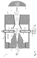
- Figure 1 shows a sectional view of an embodiment of a plasma source 1 according to the invention, which can be used for plasma treatment of an object 2, e.g. a wound, which is to be sterilized.
- the plasma source 1 comprises a conduit carrying a gas flow, wherein the conduit consists of a modified Laval nozzle 3 and a conduit pipe 4.
- the Laval nozzle 3 is arranged upstream and comprises an inlet 5 for introducing a carrier gas flow into the plasma source 1. Further, the Laval nozzle 3 comprises an inner wall 6 which is shaped in such a way that the carrier gas flow within the Laval nozzle 3 comprises a subsonic flow speed (M ⁇ 1) at the inlet 5, a supersonic flow speed (M>1) at an outlet 7 of the Laval nozzle 3 and a substantially sonic flow speed (M ⁇ 1) at a bottleneck within the Laval nozzle 3. Therefore, the gas pressure at the outlet 7 of the Laval nozzle 3 is reduced, which enhances the plasma generation, which will be described in detail later.
- M ⁇ 1 subsonic flow speed
- M>1 supersonic flow speed
- M ⁇ 1 substantially sonic flow speed
- the conduit pipe 4 is disposed downstream behind the Laval nozzle 3 and comprises a funnel-shaped upstream portion and a cylindrically shaped downstream portion and an outlet 8 for applying the plasma to the surface of the object 2.
- the Laval nozzle 3 and the conduit pipe 4 are encased by a housing 9 defining an ionization chamber 10 between the Laval nozzle 3 and the conduit pipe 4 on the inside and the walls of the housing 9 on the outside.
- the Laval nozzle 3 comprises an external thread, which is screwed with an internal thread of the housing 9.
- cylindrical downstream portion of the conduit pipe 4 comprises an external thread, which is screwed with an internal thread of the housing 9.
- both the Laval nozzle 3 and the conduit pipe 4 consist of an electrically conductive material, whereas the housing 9 consists of an electrically nonconductive material.
- the plasma source 1 further comprises a plasma generator 11, which can be an AC-source, a DC-source or an RF-source depending on the excitation mechanism used for plasma generation.
- the plasma generator 11 is connected to the Laval nozzle 3 and to the conduit pipe 4, so that electrical discharges take place in the ionization chamber 10 between the downstream end of the Laval nozzle 3 and the upstream end of the conduit pipe 4, which is illustrated in the drawings by arrows.
- the supersonic flow speed (M>1) of the carrier gas flow at the outlet 7 of the Laval nozzle 3 results in a reduced gas pressure at the outlet 7 of the Laval nozzle 3. Therefore, the carrier gas flow carries away gas particles (i.e. ions, electrons, molecules) out of the ionization chamber 10, so that the gas pressure in the ionization chamber 10 is reduced thereby enhancing the efficiency of the plasma generation.
- gas particles i.e. ions, electrons, molecules
- the housing 9 comprises a connection 12 for connecting a vacuum meter or the like.
- Figure 2 shows a cross section of another embodiment of a plasma source 13 according to the invention.
- the plasma source 13 comprises a Laval nozzle 14 and a cup-shaped ionization chamber 15, which is disposed coaxially within the Laval nozzle 14.
- the plasma source 13 comprises a cover plate 16, which is screwed on the upper front side of the Laval nozzle 14.
- the cover plate 16 there are ducts for high voltage contacts 17, 18, which can be connected to a plasma generator.
- the cover plate 16 comprises a duct for a rod 19 supporting the ionization chamber 15. The rod 19 is fixed by a screw, so that the rod 19 can be adjusted axially in the direction of the arrow in order to adjust the axial position of the ionization chamber 15 within the Laval nozzle 14.
- the Laval nozzle 14 comprises an inlet 20 for introducing a carrier gas flow into the Laval nozzle 14.
- the carrier gas flows within a ring-shaped gap between the outer wall of the ionization chamber 15 and the inner wall of the Laval nozzle 14 up to the downstream end of the ionization chamber 15, where the ionization chamber touches the inner wall of the Laval nozzle 14.
- the ionization chamber 15 comprises notches 21-24 (see figure 11 ), which are arranged in the outer wall of the ionization chamber 15 at the downstream end of the ionization chamber 15, so that the carrier gas can flow through the notches 21-24.
- the ionization chamber 15 comprises two electrodes 25, 26, which are connected to the high voltage contacts 17, 18, so that an excitation takes place between the electrodes 25, 26, which is illustrated by the arrow.
- the carrier gas flowing through the notches 21-24 produces a pressure reduction at the downstream end of the ionization chamber 15, so that the carrier gas flow carries away gas particles out of the inside of the ionization chamber 15 thereby reducing the gas pressure within the ionization chamber 15, which enhances the plasma efficiency.
- the plasma source 13 comprises an outlet 27 at its downstream end for applying the plasma to the surface of the object 2.
- Figure 3 shows a modification of the plasma source 13 comprising a conduit pipe 14' instead of the Laval nozzle 14.
- the conduit pipe 14' comprises a cylindrical upstream portion, a conically widening downstream portion and a tapering middle portion.
- Figure 4 shows a modification of the embodiment of figure 2 , which is characterized in that there is only the single electrode 25 in the ionization chamber 15, whereas the Laval nozzle 14 acts as a counter electrode and is therefore made of an electrically conductive material.
- the plasma is generated within the ionization chamber 15.
- Figure 5 is a modification of the embodiment of figure 4 , which is characterized in that the Laval nozzle 14 is replaced by the conduit pipe 14' as in figure 3 .
- Figure 6 is a modification of the embodiment according to figure 5 , which is characterized in that the Laval nozzle 14 is surrounded by a magnet 28, which is generating a coaxially aligned magnetic field within the bottleneck of the Laval nozzle 14 thereby enhancing the plasma generation.
- Figure 7 is a modification of the embodiment according to figure 6 , which is characterized in that the Laval nozzle 14 is replaced by the conduit pipe 14' as mentioned above.
- Figure 8 is a modification of the embodiment according to figure 6 , which is characterized in that there is a single hollow cathode 29 disposed within the ionization chamber 15, which enhances the plasma generation.
- Figure 9 is a modification of the embodiment of figure 8 , which is characterized in that the outlet is conically widening.
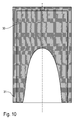
- Figure 10 shows a cross sectional view of another embodiment of an ionization chamber 30 forming a hollow cathode.
- the ionization chamber 30 consists of an electrically conductive material and comprises an electrically insulating housing 31.
- Figure 11 shows a cross section of the ionization chamber 15 along the line A-A as shown in the afore-mentioned figures. It is illustrated that the ionization chamber 15 comprises notches 21-24 at its downstream end.
- Figure 12 shows a medical device 32 for treatment of a patient 33 with non-thermal plasma.
- a medical device 32 for treatment of a patient 33 with non-thermal plasma.
- FIG 13 shows a surgeon 34 handling a cauterizer 35 for cauterising tissue in an operating field 36.
- the cauterizer 35 comprises a plasma source as described above.
- Figure 14 is a modification of the embodiment of figure 1 so that reference is made to the above description relating to figure 1 .
- the Laval nozzle 3 and the conduit pipe 4 are not connected to the plasma generator 11. Instead, there are two electrodes 37, 38 for the excitation of the plasma in the ionization chamber 10.
- the electrodes 37, 38 are radially aligned and arranged in a plane perpendicular to the gas flow between the Laval nozzle 3 and the conduit pipe 4.
- the electrode 37 is connected to ground and the electrode 38 is connected to the plasma generator 11, which is an AC/DC source.
- Figure 15 is a modification of the embodiment of figure 14 so that reference is made to the above description relating to figure 14 .
- Figure 16 is a modification of the embodiment of figure 14 so that reference is made to the above description relating to figure 14 .
- the plasma generator 11 generates a high voltage of about U ⁇ 6kV resulting in a charge time ⁇ CHARGE ⁇ 1ms, a discharge frequency f DISCHARGE ⁇ 1kHz and pulse duration ⁇ PULSE ⁇ 1ns-10ms.
- Figure 17 is a modification of the embodiment of figure 14 so that reference is made to the above description relating to figure 14 .
- One distinct feature of this embodiment is that there are permanent magnets 39, 40 being integrated into the electrodes 37, 38.
- the permanent magnets 39, 40 generate a magnetic field in the ionization chamber 10 thereby improving the plasma generation.
- Figure 18 is a modification of the embodiment of figure 17 so that reference is made to the above description relating to figure 17 .
- figure 19 is a modification of the embodiment of figure 17 so that reference is made to the above description relating to figure 17 .
- the plasma generator 11 in the form of a DC source is connected to the electrode 38 via two resistors Rv1, Rv2 and a capacitor C which is connected to ground.
Landscapes
- Physics & Mathematics (AREA)
- Engineering & Computer Science (AREA)
- Plasma & Fusion (AREA)
- Health & Medical Sciences (AREA)
- Spectroscopy & Molecular Physics (AREA)
- General Health & Medical Sciences (AREA)
- Life Sciences & Earth Sciences (AREA)
- Animal Behavior & Ethology (AREA)
- Epidemiology (AREA)
- Public Health (AREA)
- Veterinary Medicine (AREA)
- Chemical & Material Sciences (AREA)
- Analytical Chemistry (AREA)
- Apparatus For Disinfection Or Sterilisation (AREA)
- Plasma Technology (AREA)
- Surgical Instruments (AREA)
- Physical Or Chemical Processes And Apparatus (AREA)
Description
- The invention relates to a plasma source, particularly for the disinfection of wounds, according to the preamble of
claim 1. - The use of non-equilibrium plasmas for the invivo sterilization of wounds has been discussed in Stoffels, E.; Stoffels, W.: "The healing touch of a micro-plasma", published on http://www.phys.tue.nl. However, the invivo sterilization of wounds requires low temperatures of the plasma and a low electromagnetic irradiation, so that the conventional plasma sources are not suitable for the invivo sterilization of wounds.
- Further,
WO 2007/031250 A1 discloses a plasma source which is suitable for the aforementioned invivo sterilization of wounds. - High-temperature plasma sources are disclosed, for example, in
US 2007/0021748 A1 ,US 5 573 682 ,US 5 296 672 ,FR 1 376 216US 6 114 649 andUS 6 121 569 . Other types of conventional plasma sources are disclosed inWO 2005/026650 A2 andUS 3 692 431 . However, these plasma sources are not suitable for the invivo sterilization of wounds which requires a low temperature plasma. - Therefore, it is a general object of the invention to improve the plasma generation within a plasma source which is suitable for the invivo sterilization of wounds.
- This object is achieved by a plasma source according to the invention as defined in
claim 1. - According to the invention, a plasma source is provided comprising an ionization chamber in which a plasma is generated. Further, the plasma source comprises a conduit carrying a gas flow of a carrier gas (e.g. ambient air, argon or nitrogen). The plasma source according to the invention is characterized in that the ionization chamber is connected to the conduit, so that the gas flow in the conduit carries away gas particles (e.g. ions, electrons, atoms) out of the ionization chamber thereby reducing the pressure in the ionization chamber. The pressure reduction in the ionization chamber advantageously yields an improvement in the efficiency of the plasma generation since the ionizability of gases generally declines with a rising pressure. Therefore, it is easier and more efficient to generate a plasma in a gas having a low pressure.
- In a preferred embodiment of the invention, the conduit carrying the gas flow comprises a nozzle, wherein the ionization chamber is connected to the conduit downstream the nozzle. In this embodiment, the pressure reduction within the ionization chamber is produced by the gas flow in the conduit downstream the nozzle.
- Preferably, the nozzle is a Venturi nozzle or a Laval nozzle. When using a Laval nozzle, the nozzle generates a shock wave within the carrier gas flow thereby increasing the flow speed of the carrier gas flow at the junction connecting the ionization chamber to the conduit, which in turn results in a pressure reduction. However, it should be noted that the invention is not restricted to the aforementioned types of nozzles.
- However, it should be noted that the nozzle is preferably shaped in such way that the gas flow in the conduit comprises a subsonic flow speed (M<1) upstream the nozzle, a supersonic flow speed (M>1) downstream nozzle and/or a substantially sonic flow speed (M≈1) in the nozzle. Such a distribution of the flow speeds along the conduit produces the desired pressure reduction in the supersonic gas flow in the conduit according to the well-known laws of Bernoulli.
- In a preferred embodiment of the invention, the ionization chamber is ring-shaped and surrounds the conduit. In this embodiment, the nozzle and the surrounding ionization chamber can be arranged in the same cross sectional plain. Alternatively, it is possible that the ionization chamber is axially displaced with regard to the nozzle. Preferably, the ionization chamber is displaced axially in flow direction relative to the nozzle of the conduit carrying the gas flow. In other words, the ionization chamber is preferably arranged downstream the nozzle. Therefore, the junction of the ionization chamber and the conduit is located downstream the nozzle, where the pressure is reduced as explained above.
- In another embodiment of the invention, the ionization chamber is cup-shaped and open in flow direction, wherein the ionization chamber is disposed within the conduit, particularly within the nozzle. In this embodiment, the cup-shaped ionization chamber and the surrounding conduit (e.g. the nozzle) are preferably arranged coaxially, so that the gas flow in the conduit flows in the ring-shaped gap between the inner wall of the nozzle and the outer surface of the cup-shaped ionization chamber. Then, the gas flow in the ring-shaped gap passes the ionization chamber and carries away gas particles out of the interior of the ionization chamber thereby reducing the pressure within the ionization chamber.
- In the aforementioned embodiment, the cup-shaped ionization chamber preferably touches the inner surface of the nozzle at the downstream end of the ionization chamber thereby closing the aforementioned ring-shaped gap between the inner surface of the nozzle and the outer surface of the cup-shaped ionization chamber. However, the cup-shaped ionization chamber preferably comprises axially arranged notches at the ring-shaped contact point between the ionization chamber and the nozzle, so that the gas flow in the ring-shaped gap between the inner surface of the nozzle and the outer surface of the ionization chamber can flow through these notches.
- Further, the cup-shaped ionization chamber preferably comprises an axial position, which is adjustable in axial direction, i.e. the cup-shaped ionization chamber can be adjusted axially relative to the surrounding conduit.
- Further, the plasma source according to the invention preferably comprises a first electrode and a second electrode for generating the plasma in the ionization chamber. However, the invention is not restricted to electrode arrangements comprising two electrodes for plasma generation. It is also possible to use electrode arrangements comprising more than two electrodes as disclosed in
WO 2007/031250 A1 , which is therefore incorporated by a reference herein. - In a preferred embodiment of the invention, the first electrode is formed by the nozzle, whereas the second electrode is formed by a conic part of the conduit, wherein the conic part of the conduit is tapering in flow direction and surrounding the nozzle as already mentioned above. In this embodiment of the invention, the nozzle empties into the funnel-shaped conic part of the conduit.
- In another embodiment of the invention, the first electrode and the second electrode are both disposed within the ionization chamber. Such an electrode arrangement is preferred in the aforementioned embodiment comprising a cup-shaped ionization chamber.
- In yet another embodiment of the invention, the first electrode is formed by the conduit, particularly by the nozzle, whereas the second electrode is disposed alone within the ionization chamber. In this embodiment, electrical discharges take place between the inner surface of the conduit on the one hand and the second electrode in the ionization chamber on the other hand. Therefore, different electrical potentials are applied to the conduit on the one hand and to the second electrode in the ionization chamber on the other hand. For example, the conduit can be electrically grounded, whereas a positive or negative high voltage potential is applied to the second electrode in the ionization chamber.
- The plasma generation within the ionization chamber generally produces radio frequency (RF) radiation or microwaves, which can be shielded by the walls of the ionization chamber or by the walls of the surrounding conduit in order to reduce RF or microwave irradiation of the plasma source. Further, it is possible to encase the plasma source by a housing made from an electrically conductive material in order to reduce the RF or microwave irradiation.
- Further, the plasma source according to the invention can be configured in such a way that there is no direct radiation path from the inside of the ionization chamber into the conduit carrying the gas flow and through the outlet of the conduit, so that the plasma source is substantially free of plasma generated electro magnetic irradiation, e.g. ultraviolet irradiation.
- However, in some applications of a plasma source ultraviolet irradiation might be desirable, e.g. for sterilization of wounds or for decontamination of surfaces. Therefore, it is also possible that the plasma source according to the invention is configured in such a way that there is a direct radiation path from the inside of the ionization chamber into the conduit carrying the gas flow and through the outlet of the conduit, so that the plasma source emits plasma generated electromagnetic irradiation.
- Further, the ionization chamber may comprise walls, which are at least partially transparent thereby enabling a visual control of the plasma generation within the ionization chamber. For example, a window can be disposed in the walls of the ionization chamber and/or in the walls of the surrounding conduits so that the plasma generation in the ionization chamber can be visually monitored through the window, which is therefore preferably transparent for visible light and intransparent for ultraviolet light. Further, a photo diode, a CCD camera (CCD: Charge coupled device) or any other optical sensor can be used for monitoring the plasma generation through the window.
- It should further be noted that the ionization chamber may comprise a connection for connecting a vacuum meter or the like.
- In another embodiment of the invention, the plasma source comprises a magnet generating a magnetic field in the ionization chamber and/or downstream the ionization chamber in a conduit, wherein the magnetic field enhances the plasma generation. This is reasonable if the mean free path of the charge carriers (i.e. electrons) of the plasma is sufficient to produce a significant effect of the magnetic field on the charge carriers due to the Lorentz force.
- It should further be mentioned that the conduit carrying the carrier gas flow comprises an inlet for introducing the gas flow into the conduit and an outlet for dispensing the gas flow with the intermixed plasma onto an object, which is to be treated with the plasma.
- Further, the vacuum in the ionization chamber is preferably in the range between 5mbar to 900mbar and more preferably in the range between 400mbar to 600mbar. However, the invention is not restricted to the aforementioned pressure range.
- Moreover, it should be noted that the gas flow introduced into the conduit preferably consists of ambient air, nitrogen, noble gas (e.g. argon) or one of the aforementioned gases with additives, particularly with carbon dioxide.
- Further, the gas flow in the conduit preferably amounts to less than 50l/min., 40l/min., 30l/min., 20l/min., or even to less than 10l/min. However, the invention is not restricted to the aforementioned limits for the gas flow in the conduit. Further, the plasma source according to the invention preferably comprises a plasma generator driving the electrodes within the ionization chamber. In one embodiment of the invention the plasma generator produces a direct current (DC) excitation in the ionization chamber. In another embodiment, the plasma generator produces an alternating current (AC) excitation in the ionization chamber, particularly a radio frequency (RF) excitation.
- It should further be noted that the plasma source according to the invention generates a non-thermal plasma having a low temperature, so that the plasma can be used to treat wounds or other temperature sensitive surfaces. Therefore, the plasma generated by the plasma source preferably has a temperature of less than 100°C, 75°C, 50°C, 40°C or even less than 30°C measured at the outlet of the plasma source.
- It has already been mentioned that the gas flow in the conduit carries away gas particles out of the ionization chamber thereby reducing the pressure within the ionization chamber. In the preferred embodiment of the invention, different types of gas particles are carried away out of the ionization chamber, e.g. gas molecules, gas atoms, gas ions and/or electrons.
- It should further be noted that the invention is also directed to a medical device comprising a plasma source as mentioned above. For example, sterilizers or cauterizers may be equipped with the plasma source according to the invention. Moreover, the invention is directed to a method of non-therapeutic use of a plasma source according to the invention for treatment of an object, which can be sterilized or decontaminated by the plasma.
- The non-destructive decontamination of objects may be of interest in astronautics, e.g. when parts of a space craft shall be decontaminated after return to earth. Therefore, the plasma source according to the invention can be used to decontaminate electronic circuits, electric or electronic components, subassemblies of a space craft or the surface of a space-suit.
- The invention and its particular features and advantages will become more apparent from the following detailed description considered with reference to the accompanying drawings.
-
- Figure 1
- is a sectional view of a plasma source according to the invention comprising a Laval nozzle and a funnel-shaped counter electrode,
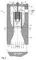
- Figure 2
- is a cross sectional view of another embodiment of a plasma source according to the invention comprising a nozzle and a cup-shape ionization chamber within the nozzle.
- Figure 3
- is a modification of the embodiment according to
figure 3 , wherein the nozzle comprises a conically widening outlet. - Figure 4
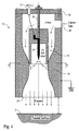
- is a sectional view of a modification of
figure 3 , wherein a single electrode is disposed within the ionization chamber. - Figure 5
- is a sectional view of a modification of the embodiment according to
figure 4 , wherein the nozzle comprises a conically widening outlet. - Figure 6
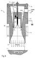
- is a sectional view of a modification of the embodiment according to
figure 4 , wherein a magnet is surrounding the nozzle generating a magnetic field within the nozzle. - Figure 7
- is a modification of the embodiment according to
figure 6 , wherein the nozzle comprises a conically widening outlet. - Figure 8
- is a modification of the embodiment according to
figure 6 comprising a hollow cathode for plasma generation. - Figure 9
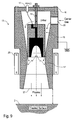
- is a cross sectional view of a modification of the embodiment according to
figure 8 , wherein the nozzle comprises a conically widening outlet. - Figure 10
- is an enlarged cross sectional view of the hollow cathode for plasma generation.
- Figure 11
- is a cross sectional view of the ionization chamber along the line A-A in
figure 2 . - Figure 12
- is a schematic view of a medical device for treatment of a patient with plasma.
- Figure 13
- is a schematical view showing a surgeon using the plasma source as a cauterizer.
- Figure 14
- is a schematical view showing a plasma source similar to the one of
Figure 1 but with a different electrode arrangement. - Figure 15
- is a modification of the embodiment of
figure 14 comprising two DC sources for generating the plasma. - Figure 16
- is a modification of the embodiment of
figure 14 comprising a free-running pulsed plasma excitation. - Figure 17
- is a schematical view showing a plasma source similar to the one of
Figure 15 but with an additional magnet. - Figure 18
- is a modification of the embodiment of
figure 17 comprising two DC sources for generating the plasma. - Figure 19
- is a modification of the embodiment of
figure 17 comprising a free-running pulsed plasma excitation. -
Figure 1 shows a sectional view of an embodiment of aplasma source 1 according to the invention, which can be used for plasma treatment of anobject 2, e.g. a wound, which is to be sterilized. - The
plasma source 1 comprises a conduit carrying a gas flow, wherein the conduit consists of a modifiedLaval nozzle 3 and a conduit pipe 4. - The
Laval nozzle 3 is arranged upstream and comprises aninlet 5 for introducing a carrier gas flow into theplasma source 1. Further, theLaval nozzle 3 comprises aninner wall 6 which is shaped in such a way that the carrier gas flow within theLaval nozzle 3 comprises a subsonic flow speed (M<1) at theinlet 5, a supersonic flow speed (M>1) at anoutlet 7 of theLaval nozzle 3 and a substantially sonic flow speed (M≈1) at a bottleneck within theLaval nozzle 3. Therefore, the gas pressure at theoutlet 7 of theLaval nozzle 3 is reduced, which enhances the plasma generation, which will be described in detail later. - The conduit pipe 4 is disposed downstream behind the
Laval nozzle 3 and comprises a funnel-shaped upstream portion and a cylindrically shaped downstream portion and anoutlet 8 for applying the plasma to the surface of theobject 2. - It should further be noted that there is an axial displacement between the
Laval nozzle 3 and the conduit pipe 4, so that there is a gap between theLaval nozzle 3 and the conduit pipe 4, whereas the gas jet is flowing freely in the gap thereby generating a vacuum. - Further, the
Laval nozzle 3 and the conduit pipe 4 are encased by ahousing 9 defining anionization chamber 10 between theLaval nozzle 3 and the conduit pipe 4 on the inside and the walls of thehousing 9 on the outside. - The
Laval nozzle 3 comprises an external thread, which is screwed with an internal thread of thehousing 9. - Further, the cylindrical downstream portion of the conduit pipe 4 comprises an external thread, which is screwed with an internal thread of the
housing 9. - In this embodiment, both the
Laval nozzle 3 and the conduit pipe 4 consist of an electrically conductive material, whereas thehousing 9 consists of an electrically nonconductive material. - The
plasma source 1 further comprises aplasma generator 11, which can be an AC-source, a DC-source or an RF-source depending on the excitation mechanism used for plasma generation. Theplasma generator 11 is connected to theLaval nozzle 3 and to the conduit pipe 4, so that electrical discharges take place in theionization chamber 10 between the downstream end of theLaval nozzle 3 and the upstream end of the conduit pipe 4, which is illustrated in the drawings by arrows. - It has already been mentioned above that the supersonic flow speed (M>1) of the carrier gas flow at the
outlet 7 of theLaval nozzle 3 results in a reduced gas pressure at theoutlet 7 of theLaval nozzle 3. Therefore, the carrier gas flow carries away gas particles (i.e. ions, electrons, molecules) out of theionization chamber 10, so that the gas pressure in theionization chamber 10 is reduced thereby enhancing the efficiency of the plasma generation. - Further, the
housing 9 comprises aconnection 12 for connecting a vacuum meter or the like. -
Figure 2 shows a cross section of another embodiment of aplasma source 13 according to the invention. - The
plasma source 13 comprises aLaval nozzle 14 and a cup-shapedionization chamber 15, which is disposed coaxially within theLaval nozzle 14. - Further, the
plasma source 13 comprises acover plate 16, which is screwed on the upper front side of theLaval nozzle 14. In thecover plate 16, there are ducts forhigh voltage contacts cover plate 16 comprises a duct for arod 19 supporting theionization chamber 15. Therod 19 is fixed by a screw, so that therod 19 can be adjusted axially in the direction of the arrow in order to adjust the axial position of theionization chamber 15 within theLaval nozzle 14. - Further, the
Laval nozzle 14 comprises aninlet 20 for introducing a carrier gas flow into theLaval nozzle 14. - The carrier gas flows within a ring-shaped gap between the outer wall of the
ionization chamber 15 and the inner wall of theLaval nozzle 14 up to the downstream end of theionization chamber 15, where the ionization chamber touches the inner wall of theLaval nozzle 14. - Therefore, the
ionization chamber 15 comprises notches 21-24 (seefigure 11 ), which are arranged in the outer wall of theionization chamber 15 at the downstream end of theionization chamber 15, so that the carrier gas can flow through the notches 21-24. - Further, the
ionization chamber 15 comprises twoelectrodes high voltage contacts electrodes - It should further be noted that the carrier gas flowing through the notches 21-24 produces a pressure reduction at the downstream end of the
ionization chamber 15, so that the carrier gas flow carries away gas particles out of the inside of theionization chamber 15 thereby reducing the gas pressure within theionization chamber 15, which enhances the plasma efficiency. - Further, the
plasma source 13 comprises anoutlet 27 at its downstream end for applying the plasma to the surface of theobject 2. -
Figure 3 shows a modification of theplasma source 13 comprising a conduit pipe 14' instead of theLaval nozzle 14. The conduit pipe 14' comprises a cylindrical upstream portion, a conically widening downstream portion and a tapering middle portion. -
Figure 4 shows a modification of the embodiment offigure 2 , which is characterized in that there is only thesingle electrode 25 in theionization chamber 15, whereas theLaval nozzle 14 acts as a counter electrode and is therefore made of an electrically conductive material. - It should further be noted that the plasma is generated within the
ionization chamber 15. -
Figure 5 is a modification of the embodiment offigure 4 , which is characterized in that theLaval nozzle 14 is replaced by the conduit pipe 14' as infigure 3 . -
Figure 6 is a modification of the embodiment according tofigure 5 , which is characterized in that theLaval nozzle 14 is surrounded by amagnet 28, which is generating a coaxially aligned magnetic field within the bottleneck of theLaval nozzle 14 thereby enhancing the plasma generation. -
Figure 7 is a modification of the embodiment according tofigure 6 , which is characterized in that theLaval nozzle 14 is replaced by the conduit pipe 14' as mentioned above. -
Figure 8 is a modification of the embodiment according tofigure 6 , which is characterized in that there is a singlehollow cathode 29 disposed within theionization chamber 15, which enhances the plasma generation. -
Figure 9 is a modification of the embodiment offigure 8 , which is characterized in that the outlet is conically widening. -
Figure 10 shows a cross sectional view of another embodiment of anionization chamber 30 forming a hollow cathode. Theionization chamber 30 consists of an electrically conductive material and comprises an electrically insulatinghousing 31. -
Figure 11 shows a cross section of theionization chamber 15 along the line A-A as shown in the afore-mentioned figures. It is illustrated that theionization chamber 15 comprises notches 21-24 at its downstream end. -
Figure 12 shows amedical device 32 for treatment of a patient 33 with non-thermal plasma. In this embodiment, there are several plasma sources arranged around thepatient 33, so that the plasma is applied to the patient 33 from different sides. - Further,
figure 13 shows asurgeon 34 handling acauterizer 35 for cauterising tissue in an operating field 36. In this embodiment, thecauterizer 35 comprises a plasma source as described above. -
Figure 14 is a modification of the embodiment offigure 1 so that reference is made to the above description relating tofigure 1 . - However, the
Laval nozzle 3 and the conduit pipe 4 are not connected to theplasma generator 11. Instead, there are twoelectrodes ionization chamber 10. - The
electrodes Laval nozzle 3 and the conduit pipe 4. - The
electrode 37 is connected to ground and theelectrode 38 is connected to theplasma generator 11, which is an AC/DC source. -
Figure 15 is a modification of the embodiment offigure 14 so that reference is made to the above description relating tofigure 14 . - However, there are two
plasma generators 11 in the form of DC sources, which are connected to theelectrodes -
Figure 16 is a modification of the embodiment offigure 14 so that reference is made to the above description relating tofigure 14 . - However, there is a free-running pulsed plasma excitation. Therefore, the
plasma generator 11 in the form of a DC source is connected to theelectrode 38 via two resistors Rv1≈1MΩ, Rv2≈1Ω-100kΩ and a capacitor C=1nF which is connected to ground. Theplasma generator 11 generates a high voltage of about U≈6kV resulting in a charge time τCHARGE≈1ms, a discharge frequency fDISCHARGE≈1kHz and pulse duration τPULSE≈1ns-10ms.Figure 17 is a modification of the embodiment offigure 14 so that reference is made to the above description relating tofigure 14 . - One distinct feature of this embodiment is that there are
permanent magnets 39, 40 being integrated into theelectrodes permanent magnets 39, 40 generate a magnetic field in theionization chamber 10 thereby improving the plasma generation. -
Figure 18 is a modification of the embodiment offigure 17 so that reference is made to the above description relating tofigure 17 . - However, there are two
plasma generators 11 in the form of DC source, which are connected to theelectrodes figure 19 is a modification of the embodiment offigure 17 so that reference is made to the above description relating tofigure 17 . - However, there is a free-running pulsed plasma excitation. Therefore, the
plasma generator 11 in the form of a DC source is connected to theelectrode 38 via two resistors Rv1, Rv2 and a capacitor C which is connected to ground. - Although the invention has been described with reference to the particular arrangement of parts, features and the like, these are not intended to exhaust all possible arrangements of features, and indeed many other modifications and variations will be ascertainable to those of skill in the art, the invention being defined by the appended claims.
-
- 1
- Plasma source
- 2
- Object
- 3
- Laval nozzle
- 4
- Conduit pipe
- 5
- Inlet
- 6
- Inner wall
- 7
- Outlet
- 8
- Outlet
- 9
- Housing
- 10
- Ionization chamber
- 11
- Plasma generator
- 12
- Connection
- 13
- Plasma source
- 14
- Laval nozzle
- 14'
- Conduit pipe
- 15
- Ionization chamber
- 16
- Cover plate
- 17, 18
- High voltage contacts
- 19
- Rod
- 20
- Inlet
- 21-24
- Notches
- 25, 26
- Electrodes
- 27
- Outlet
- 28
- Magnet
- 29
- Hollow cathode
- 30
- Ionization chamber
- 31
- Housing
- 32
- Medical device
- 33
- Patient
- 34
- Surgeon
- 35
- Cauterizer
- 36
- Operating field
- 37
- Electrode
- 38
- Electrode
- 39
- Permanent magnet
- 40
- Permanent magnet
Claims (12)
- Plasma source (1) for generating a low temperature plasma, the plasma having a temperature suitable for the in-vivo sterilization of wounds, comprising:- a conduit (3,4) carrying a gas flow, the conduit (3,4) comprising a Laval nozzle (3) and an inlet (5) arranged upstream of the Laval nozzle (3) for introducing a gas flow into the Laval nozzle (3), the Laval nozzle (3) being arranged upstream of an ionization chamber (10), the conduit (3,4) further comprising a conduit pipe (4) arranged downstream of the ionization chamber and an outlet (8) downstream of the conduit pipe (4), the plasma source further comprising- a housing encasing the Laval nozzle (3) and the conduit pipe (4) and defining the ionization chamber (10) between the Laval nozzle (3) and the conduit pipe (4), wherein- the Laval nozzle (3) and the conduit pipe (4) are configured to reduce a pressure in the ionization chamber (10) when a gas flow is carried by the conduit (3,4), wherein- the plasma source (1) comprises a plasma generator (11) configured to generate a low temperature plasma inside of the ionization chamber (10) between the Laval nozzle (3) and the conduit pipe (4), and wherein- the outlet (8) is configured for applying the plasma to a surface.
- Plasma source (1) according to claim 1, characterized bya) a subsonic flow speed (M<1) of the gas flow in the conduit (3, 4) upstream the Laval nozzle (3), and/orb) a supersonic flow speed (M>1) of the gas flow in the conduit (3, 4) downstream the Laval nozzle (3), and/orc) a substantially sonic flow speed (M≈1) of the gas flow in the Laval nozzle (3).
- Plasma source (1) according to one of the preceding claims, characterized in thata) the ionization chamber (10) is ring-shaped and surrounds the conduit (3, 4), and/orb) there is a ring-shaped plasma discharge within the ionization chamber (10), wherein the plasma discharge surrounds the conduit (3,4).
- Plasma source (1) according to one of the preceding claims, characterized in thata) a first electrode and a second electrode are provided for generating the plasma in the ionization chamber (10) and/orb) a first electrode is formed by the Laval nozzle (3) and a second electrode is formed by a conic part of the conduit pipe (4), wherein the conic part is tapering in flow direction and surrounding the Laval nozzle (3), orc) a first electrode (37) and a second electrode (38) are both disposed within the ionization chamber (10).
- Plasma source (1) according to one of the preceding claims, characterized in thata) microwaves are generated within the ionization chamber (10) due to the plasma generation, andb) the microwaves generated within the ionization chamber (10) are shielded by the ionization chamber (10) or by a housing made from an electrically conductive material in order to reduce microwave irradiation of the plasma source (1), andc) there is no direct radiation path from the inside of the ionization chamber (10) into the conduit (3, 4) and through the outlet of the conduit (3,4), so that the plasma source (1) is substantially free of plasma generated electromagnetic irradiation, ord) there is a direct radiation path from the inside of the ionisation chamber into the conduit (4) and through the outlet of the conduit (4), so that the plasma source (1) emits plasma generated electromagnetic irradiation, and/ore) the ionization chamber (10) comprises walls, which are at least partially transparent thereby enabling a visual control of the plasma generation within the ionization chamber (10), and/orf) the ionization chamber (10) comprises a window made from a material, which is transparent for visible light and intransparent for ultraviolet light, and/org) the ionization chamber (10) comprises a connection (12) for connecting a vacuum meter or the like.
- Plasma source (1) according to one of the preceding claims, characterized by a magnet (39,40) generating a magnetic field in the ionization chamber (10) and/or downstream the ionization chamber (10) in the conduit (3,4), wherein said magnetic field enhances the plasma generation.
- Plasma source (1) according to one of the preceding claims, characterized in thata) the gas flow introduced into the conduit (3,4) substantially consists of ambient air or nitrogen or noble gas, particularly argon, or one of the aforementioned gases with additives, particularly with carbon dioxide, and/orb) the gas flow in the conduit (3,4) amounts to less than 50 l/min., 40 l/min., 30 l/min., 20 l/min. or 10 l/min., and/orc) the plasma source (1) is adapted to generate plasma having a temperature of less than 100 °C, 75 °C, 50 °C, 40 °C, or 30 °C, and/ord) the vacuum generated in the ionization chamber (10) is in the range between 5 mbar to 900 mbar.
- Plasma source (1) according to one of the preceding claims, characterized by a plasma generator (11) fora) a direct current excitation orb) an alternating current excitation, particularly a radio frequency excitation, of the plasma within the ionization chamber (10).
- Plasma source (1) according to one of the preceding claims, characterized in that the first electrode (37) and the second electrode (38) are radially aligned and arranged in a plane perpendicular to the gas flow between the Laval nozzle (3) and the conduit pipe (4).
- Medical device (32; 35), particularly sterilizer or cauterizer (5), comprising a plasma source (1) according to one of the preceding claims.
- Method of non-therapeutic use of a plasma source (1) according to one of claims 1 to 9 for treatment of an object (2).
- Method according to claim 11, whereina) the treated object (2) is decontaminated by the plasma, which is generated by the plasma source (1), and/orb) the decontaminated object (2) is selected from a group consisting of:- an electronic circuit,- an electric component,- an electronic component,- a component of a spacecraft,- a subassembly of a spacecraft,- a space-suit.
Priority Applications (1)
| Application Number | Priority Date | Filing Date | Title |
|---|---|---|---|
| EP08749307.8A EP2147582B1 (en) | 2007-05-15 | 2008-05-02 | Plasma source |
Applications Claiming Priority (3)
| Application Number | Priority Date | Filing Date | Title |
|---|---|---|---|
| EP07009716A EP1993329A1 (en) | 2007-05-15 | 2007-05-15 | Plasma source |
| EP08749307.8A EP2147582B1 (en) | 2007-05-15 | 2008-05-02 | Plasma source |
| PCT/EP2008/003568 WO2008138504A1 (en) | 2007-05-15 | 2008-05-02 | Plasma source |
Publications (2)
| Publication Number | Publication Date |
|---|---|
| EP2147582A1 EP2147582A1 (en) | 2010-01-27 |
| EP2147582B1 true EP2147582B1 (en) | 2016-10-12 |
Family
ID=38529476
Family Applications (2)
| Application Number | Title | Priority Date | Filing Date |
|---|---|---|---|
| EP07009716A Withdrawn EP1993329A1 (en) | 2007-05-15 | 2007-05-15 | Plasma source |
| EP08749307.8A Not-in-force EP2147582B1 (en) | 2007-05-15 | 2008-05-02 | Plasma source |
Family Applications Before (1)
| Application Number | Title | Priority Date | Filing Date |
|---|---|---|---|
| EP07009716A Withdrawn EP1993329A1 (en) | 2007-05-15 | 2007-05-15 | Plasma source |
Country Status (6)
| Country | Link |
|---|---|
| US (1) | US8926920B2 (en) |
| EP (2) | EP1993329A1 (en) |
| JP (1) | JP5663819B2 (en) |
| KR (1) | KR20100017374A (en) |
| CN (1) | CN101731024A (en) |
| WO (1) | WO2008138504A1 (en) |
Cited By (3)
| Publication number | Priority date | Publication date | Assignee | Title |
|---|---|---|---|---|
| DE102020203399A1 (en) | 2020-03-17 | 2021-09-23 | Henkel Ag & Co. Kgaa | Washer with generator of cold plasma |
| DE102020203397A1 (en) | 2020-03-17 | 2021-09-23 | Henkel Ag & Co. Kgaa | Increased performance in washing and cleaning |
| DE102020203400A1 (en) | 2020-03-17 | 2021-09-23 | Henkel Ag & Co. Kgaa | Washing machine or dishwasher with generator of cold plasma |
Families Citing this family (53)
| Publication number | Priority date | Publication date | Assignee | Title |
|---|---|---|---|---|
| CN105154856B (en) | 2008-08-04 | 2018-08-10 | 北美Agc平板玻璃公司 | Plasma source and with the chemical vapor deposition of plasma enhancing come the method for depositing thin film coatings |
| EP2160081A1 (en) | 2008-08-27 | 2010-03-03 | Max-Planck-Gesellschaft zur Förderung der Wissenschaften e.V. | Non-thermal plasma for wound treatment and associated apparatus and method |
| EP2170022A1 (en) | 2008-09-25 | 2010-03-31 | Max-Planck-Gesellschaft zur Förderung der Wissenschaften e.V. | Plasma applicator and corresponding method |
| US8604379B2 (en) * | 2009-02-08 | 2013-12-10 | Ap Solutions, Inc. | Plasma source with integral blade and method for removing materials from substrates |
| EP2223704A1 (en) | 2009-02-17 | 2010-09-01 | Max-Planck-Gesellschaft zur Förderung der Wissenschaften e.V. | Treating device for treating a body part of a patient with a non-thermal plasma |
| WO2011110191A1 (en) | 2010-03-10 | 2011-09-15 | Max-Planck-Gesellschaft zur Förderung der Wissenschaften e. V. | Method and arrangement for treating an object with a low- temperature plasma |
| GB201006383D0 (en) | 2010-04-16 | 2010-06-02 | Linde Ag | Device for providing a flow of plasma |
| DE102010020591A1 (en) * | 2010-05-14 | 2011-11-17 | Fraunhofer-Gesellschaft zur Förderung der angewandten Forschung e.V. | Plasma generator and methods for generating and using an ionized gas |
| EP2445320A1 (en) | 2010-10-25 | 2012-04-25 | Max-Planck-Gesellschaft zur Förderung der Wissenschaften e.V. | Energy harvesting cold atmospheric plasma generator |
| DE102011003533A1 (en) | 2011-02-02 | 2012-08-02 | Beiersdorf Ag | Deodorant skin film |
| DE102011003782A1 (en) | 2011-02-08 | 2012-08-09 | Meiko Maschinenbau Gmbh & Co. Kg | Cleaning device for cleaning items to be cleaned |
| EP2678046B1 (en) | 2011-02-25 | 2015-01-21 | Max-Planck-Gesellschaft zur Förderung der Wissenschaften e.V. | Disinfection appliance, container, use of a container and disinfection method for disinfecting a container, in particular for a food container |
| WO2012119617A1 (en) | 2011-03-10 | 2012-09-13 | Max-Planck-Gesellschaft Zur Foerderung Der Wissenschaften E.V. | Disinfection appliance and disinfection method |
| WO2012158443A2 (en) * | 2011-05-13 | 2012-11-22 | Sheperak Thomas J | Plasma directed electron beam wound care system apparatus and method |
| DE102012003557B4 (en) | 2012-02-23 | 2023-05-04 | Dräger Safety AG & Co. KGaA | Equipment and procedures for the hygienic preparation of objects |
| DE102012003555A1 (en) | 2012-02-23 | 2013-08-29 | Dräger Medical GmbH | Incubator for neonatal care and method for deinfecting same |
| US10266802B2 (en) | 2013-01-16 | 2019-04-23 | Orteron (T.O) Ltd. | Method for controlling biological processes in microorganisms |
| IL226105A (en) | 2013-01-16 | 2014-05-28 | Orteron T O Ltd | System and method for generating modified plasma |
| DE102013103248A1 (en) * | 2013-03-28 | 2014-10-02 | Adelheid Mirwald | A method for creating a sterile area for an operation, examination or treatment of at least a portion of an object, in particular a person |
| JP6513020B2 (en) * | 2013-04-15 | 2019-05-15 | 日本碍子株式会社 | Sterilizer |
| CN103418086B (en) * | 2013-08-13 | 2015-03-25 | 浙江大学 | Wound treatment device utilizing high voltage to generate plasma |
| MX2017007356A (en) | 2014-12-05 | 2018-04-11 | Agc Flat Glass Europe S A | Hollow cathode plasma source. |
| CN107615888B (en) | 2014-12-05 | 2022-01-04 | 北美Agc平板玻璃公司 | Plasma source utilizing macro-particle reduction coating and method of using plasma source for deposition of thin film coatings and surface modification |
| US20160271411A1 (en) * | 2015-03-17 | 2016-09-22 | Plasmology4, Inc. | Cold plasma pressure treatment system |
| US11490947B2 (en) | 2015-05-15 | 2022-11-08 | Clear Intradermal Technologies, Inc. | Tattoo removal using a liquid-gas mixture with plasma gas bubbles |
| JP2018520817A (en) | 2015-05-15 | 2018-08-02 | クリアイット エルエルシーClearit, Llc | Tattoo removal system and method using low temperature plasma |
| DE102015215051A1 (en) * | 2015-08-06 | 2017-02-09 | Terraplasma Gmbh | Apparatus and method for generating a plasma, and use of such a device |
| DE102015119990A1 (en) | 2015-10-06 | 2017-04-06 | Orteron (T.O) Ltd. | A method for controlling biological processes in microorganisms |
| US9721765B2 (en) | 2015-11-16 | 2017-08-01 | Agc Flat Glass North America, Inc. | Plasma device driven by multiple-phase alternating or pulsed electrical current |
| SG11201805171YA (en) * | 2015-12-18 | 2018-07-30 | Agc Flat Glass Na Inc | Hollow cathode ion source and method of extracting and accelerating ions |
| US10573499B2 (en) | 2015-12-18 | 2020-02-25 | Agc Flat Glass North America, Inc. | Method of extracting and accelerating ions |
| DE102017106482A1 (en) * | 2016-03-30 | 2017-10-05 | Leibniz-Institut für Plasmaforschung und Technologie e.V. | System and method for treating surfaces of bodies, in particular for wound treatment |
| WO2017197071A1 (en) | 2016-05-12 | 2017-11-16 | EP Technologies LLC | Methods and systems for trans-tissue substance delivery using plasmaporation |
| TWI601694B (en) * | 2016-06-06 | 2017-10-11 | 拜普生醫科技股份有限公司 | Plasma liquid generating device |
| EP3496515B1 (en) * | 2016-08-02 | 2022-09-28 | Feagle Co., Ltd | Medical device including plasma supply device and plasma enhancement member |
| WO2018089577A1 (en) | 2016-11-10 | 2018-05-17 | EP Technologies LLC | Methods and systems for generating plasma activated liquid |
| CN106492247A (en) * | 2016-12-31 | 2017-03-15 | 合肥优亿科机电科技有限公司 | Portable type atmosphere plasma sterilizing installation |
| EP3346808A1 (en) | 2017-01-06 | 2018-07-11 | INP Greifswald Leibniz-institut Fuer Plasmaforschung Und Technologie E. V. | Planar device and method for generating a plasma or reactive species |
| JP6811844B2 (en) * | 2017-04-04 | 2021-01-13 | 株式会社Fuji | Plasma generator |
| US11195702B2 (en) | 2017-04-04 | 2021-12-07 | Fuji Corporation | Plasma-generating device |
| JP2019055352A (en) * | 2017-09-20 | 2019-04-11 | 住友理工株式会社 | Plasma processing equipment |
| CN108971140A (en) * | 2018-05-12 | 2018-12-11 | 合肥杰硕真空科技有限公司 | A kind of radio frequency plasma cleaning device |
| CN108856170A (en) * | 2018-05-12 | 2018-11-23 | 合肥杰硕真空科技有限公司 | A kind of intermediate frequency plasma body cleaning device |
| EP3588533A1 (en) * | 2018-06-21 | 2020-01-01 | Nederlandse Organisatie voor toegepast- natuurwetenschappelijk onderzoek TNO | Plasma source and method of operating the same |
| CN108990246B (en) * | 2018-07-04 | 2019-11-15 | 北京理工大学 | A Plasma Contactor with Annular Ionization Chamber |
| ES1226210Y (en) * | 2018-07-25 | 2019-05-31 | Ion Biotec S L | Physical plasma device for disinfection of skin wounds |
| CN113329707B (en) | 2018-12-19 | 2024-10-18 | 科利尔皮内技术公司 | Systems and methods for tattoo removal using an applied electric field |
| US11122790B2 (en) * | 2019-12-30 | 2021-09-21 | Nbs Tek Llc | Cold plasma method and apparatus for eradication of the taxonomic class insecta |
| KR102473148B1 (en) * | 2020-03-27 | 2022-12-01 | 한국기계연구원 | Plasma supersonic flow generator |
| DE102020124739A1 (en) * | 2020-09-23 | 2022-03-24 | Ebm-Papst Mulfingen Gmbh & Co. Kg | Device for disinfecting air with electromagnetic radiation |
| WO2023114192A1 (en) * | 2021-12-13 | 2023-06-22 | Carbogenesis Llc | Systems and methods for carbon dioxide conversion |
| CN115870105B (en) * | 2023-02-21 | 2025-08-29 | 中国矿业大学 | A device for preparing cold active oil bubbles using low-temperature plasma and a flotation method |
| US12603252B2 (en) * | 2024-08-15 | 2026-04-14 | Applied Materials, Inc. | Low-flow radical gas geometrical control through two-dimensional compression between plasma source and chemical reactor |
Citations (2)
| Publication number | Priority date | Publication date | Assignee | Title |
|---|---|---|---|---|
| EP0500491A1 (en) * | 1991-02-21 | 1992-08-26 | Sulzer Metco AG | Plasma spray gun for spraying powdered or gaseous materials |
| EP1765044A1 (en) * | 2005-09-16 | 2007-03-21 | Max-Planck-Gesellschaft zur Förderung der Wissenschaften e.V. | Plasma source |
Family Cites Families (27)
| Publication number | Priority date | Publication date | Assignee | Title |
|---|---|---|---|---|
| US2922869A (en) * | 1958-07-07 | 1960-01-26 | Plasmadyne Corp | Plasma stream apparatus and methods |
| FR1376216A (en) * | 1962-12-03 | 1964-10-23 | Westinghouse Electric Corp | Arc heater |
| BE664193A (en) * | 1964-05-30 | 1965-09-16 | ||
| CA871894A (en) * | 1968-08-02 | 1971-05-25 | Canadian Titanium Pigments Limited | Plasma arc heating apparatus |
| SU437320A3 (en) * | 1969-10-31 | 1974-07-25 | Сименс Аг (Фирма) | Device for high-speed gas jet |
| US4197610A (en) * | 1977-10-17 | 1980-04-15 | California Institute Of Technology | Cleaning devices |
| JPS6021382A (en) * | 1983-07-15 | 1985-02-02 | Canon Inc | Plasma cvd apparatus |
| CA1323670C (en) * | 1988-05-17 | 1993-10-26 | Subramania Ramakrishnan | Electric arc reactor |
| US4846101A (en) * | 1988-07-01 | 1989-07-11 | Becton, Dickinson And Company | Apparatus for plasma treatment of small diameter tubes |
| JPH0694926B2 (en) | 1989-07-25 | 1994-11-24 | 荏原インフイルコ株式会社 | Method of melting incineration ash |
| US5399833A (en) * | 1993-07-02 | 1995-03-21 | Camacho; Salvador L. | Method for vitrification of fine particulate matter and products produced thereby |
| US5573682A (en) * | 1995-04-20 | 1996-11-12 | Plasma Processes | Plasma spray nozzle with low overspray and collimated flow |
| EP0938396A4 (en) * | 1996-11-01 | 2001-07-25 | George H Miley | Plasma jet source using an inertial electrostatic confinement discharge plasma |
| US6320156B1 (en) * | 1999-05-10 | 2001-11-20 | Komatsu Ltd. | Plasma processing device, plasma torch and method for replacing components of same |
| US6455014B1 (en) * | 1999-05-14 | 2002-09-24 | Mesosystems Technology, Inc. | Decontamination of fluids or objects contaminated with chemical or biological agents using a distributed plasma reactor |
| US6114649A (en) * | 1999-07-13 | 2000-09-05 | Duran Technologies Inc. | Anode electrode for plasmatron structure |
| US7011790B2 (en) | 2001-05-07 | 2006-03-14 | Regents Of The University Of Minnesota | Non-thermal disinfection of biological fluids using non-thermal plasma |
| US7090808B2 (en) * | 2001-07-09 | 2006-08-15 | Pharmaceutical Systems, Inc. | Apparatus for testing sterilization methods and materials |
| JP2003024426A (en) * | 2001-07-16 | 2003-01-28 | Sanyo Electric Co Ltd | Deodorizing device |
| US7828741B2 (en) * | 2002-12-20 | 2010-11-09 | The Charlotte-Mecklenburg Hospital Authority | Utilizing lipopolysaccharide in exhaled breath condensate to diagnose gram negative pneumonia |
| US20040265167A1 (en) * | 2003-06-30 | 2004-12-30 | Todd Morrison | Sterilization vacuum chamber door closure |
| WO2005026650A2 (en) * | 2003-09-15 | 2005-03-24 | Gamma Kdg Systems Sa | Plasma flare ir and uv emitting devices |
| JP2005126737A (en) | 2003-10-21 | 2005-05-19 | Riken Corp | Arc type evaporation source |
| US20050258149A1 (en) * | 2004-05-24 | 2005-11-24 | Yuri Glukhoy | Method and apparatus for manufacture of nanoparticles |
| US20060263275A1 (en) * | 2005-05-09 | 2006-11-23 | Liconic Ag | Cabinet and sterilizing lamp |
| JP4756929B2 (en) | 2005-06-22 | 2011-08-24 | 荏原環境プラント株式会社 | Plasma melting furnace |
| SE529058C2 (en) * | 2005-07-08 | 2007-04-17 | Plasma Surgical Invest Ltd | Plasma generating device, plasma surgical device, use of a plasma surgical device and method for forming a plasma |
-
2007
- 2007-05-15 EP EP07009716A patent/EP1993329A1/en not_active Withdrawn
-
2008
- 2008-05-02 KR KR1020097024607A patent/KR20100017374A/en not_active Abandoned
- 2008-05-02 WO PCT/EP2008/003568 patent/WO2008138504A1/en not_active Ceased
- 2008-05-02 US US12/598,988 patent/US8926920B2/en active Active
- 2008-05-02 EP EP08749307.8A patent/EP2147582B1/en not_active Not-in-force
- 2008-05-02 JP JP2010507823A patent/JP5663819B2/en active Active
- 2008-05-02 CN CN200880016098A patent/CN101731024A/en active Pending
Patent Citations (2)
| Publication number | Priority date | Publication date | Assignee | Title |
|---|---|---|---|---|
| EP0500491A1 (en) * | 1991-02-21 | 1992-08-26 | Sulzer Metco AG | Plasma spray gun for spraying powdered or gaseous materials |
| EP1765044A1 (en) * | 2005-09-16 | 2007-03-21 | Max-Planck-Gesellschaft zur Förderung der Wissenschaften e.V. | Plasma source |
Cited By (3)
| Publication number | Priority date | Publication date | Assignee | Title |
|---|---|---|---|---|
| DE102020203399A1 (en) | 2020-03-17 | 2021-09-23 | Henkel Ag & Co. Kgaa | Washer with generator of cold plasma |
| DE102020203397A1 (en) | 2020-03-17 | 2021-09-23 | Henkel Ag & Co. Kgaa | Increased performance in washing and cleaning |
| DE102020203400A1 (en) | 2020-03-17 | 2021-09-23 | Henkel Ag & Co. Kgaa | Washing machine or dishwasher with generator of cold plasma |
Also Published As
| Publication number | Publication date |
|---|---|
| CN101731024A (en) | 2010-06-09 |
| KR20100017374A (en) | 2010-02-16 |
| EP1993329A1 (en) | 2008-11-19 |
| EP2147582A1 (en) | 2010-01-27 |
| JP2010530115A (en) | 2010-09-02 |
| US20100130911A1 (en) | 2010-05-27 |
| JP5663819B2 (en) | 2015-02-04 |
| WO2008138504A1 (en) | 2008-11-20 |
| WO2008138504A8 (en) | 2009-12-17 |
| US8926920B2 (en) | 2015-01-06 |
Similar Documents
| Publication | Publication Date | Title |
|---|---|---|
| US8926920B2 (en) | Plasma source | |
| CA2572391C (en) | Microwave plasma nozzle with enhanced plume stability and heating efficiency | |
| US8471171B2 (en) | Cold air atmospheric pressure micro plasma jet application method and device | |
| US9339783B2 (en) | Tubular floating electrode dielectric barrier discharge for applications in sterilization and tissue bonding | |
| US7572998B2 (en) | Method and device for creating a micro plasma jet | |
| JP5848705B2 (en) | Cold plasma jet generator | |
| EP2208404B1 (en) | Transient plasma ball generation system at long distance | |
| US20130202496A1 (en) | Cold plasma jet hand sanitizer | |
| WO1996040298A1 (en) | Electrodeless sterilizer using ultraviolet and/or ozone | |
| WO2012122045A2 (en) | Plasma apparatus for biological decontamination and sterilization and method for use | |
| Laroussi et al. | Cold atmospheric pressure plasma sources for cancer applications | |
| KR102522433B1 (en) | Plasma generator | |
| Veeraiah et al. | Characterization of plasma based on the electrode size of atmospheric pressure plasma jet (APPJ) | |
| Li et al. | Development of hand-held needle–ring–ring self-excited plasma device | |
| KR102479754B1 (en) | Plasma-based Beauty Equipment | |
| JP2014018703A (en) | Electric field generating device | |
| Javanmard et al. | Experimental study of characteristics of plasma action on helium flow in cold atmospheric pressure plasma jet |
Legal Events
| Date | Code | Title | Description |
|---|---|---|---|
| PUAI | Public reference made under article 153(3) epc to a published international application that has entered the european phase |
Free format text: ORIGINAL CODE: 0009012 |
|
| 17P | Request for examination filed |
Effective date: 20091019 |
|
| AK | Designated contracting states |
Kind code of ref document: A1 Designated state(s): AT BE BG CH CY CZ DE DK EE ES FI FR GB GR HR HU IE IS IT LI LT LU LV MC MT NL NO PL PT RO SE SI SK TR |
|
| AX | Request for extension of the european patent |
Extension state: AL BA MK RS |
|
| DAX | Request for extension of the european patent (deleted) | ||
| 17Q | First examination report despatched |
Effective date: 20150612 |
|
| REG | Reference to a national code |
Ref country code: DE Ref legal event code: R079 Ref document number: 602008046786 Country of ref document: DE Free format text: PREVIOUS MAIN CLASS: H05H0001240000 Ipc: H05H0001340000 |
|
| GRAP | Despatch of communication of intention to grant a patent |
Free format text: ORIGINAL CODE: EPIDOSNIGR1 |
|
| RIC1 | Information provided on ipc code assigned before grant |
Ipc: H05H 1/34 20060101AFI20160405BHEP |
|
| INTG | Intention to grant announced |
Effective date: 20160421 |
|
| GRAS | Grant fee paid |
Free format text: ORIGINAL CODE: EPIDOSNIGR3 |
|
| GRAA | (expected) grant |
Free format text: ORIGINAL CODE: 0009210 |
|
| AK | Designated contracting states |
Kind code of ref document: B1 Designated state(s): AT BE BG CH CY CZ DE DK EE ES FI FR GB GR HR HU IE IS IT LI LT LU LV MC MT NL NO PL PT RO SE SI SK TR |
|
| REG | Reference to a national code |
Ref country code: GB Ref legal event code: FG4D |
|
| REG | Reference to a national code |
Ref country code: CH Ref legal event code: EP |
|
| REG | Reference to a national code |
Ref country code: AT Ref legal event code: REF Ref document number: 837490 Country of ref document: AT Kind code of ref document: T Effective date: 20161015 |
|
| REG | Reference to a national code |
Ref country code: IE Ref legal event code: FG4D |
|
| REG | Reference to a national code |
Ref country code: DE Ref legal event code: R096 Ref document number: 602008046786 Country of ref document: DE |
|
| REG | Reference to a national code |
Ref country code: LT Ref legal event code: MG4D |
|
| REG | Reference to a national code |
Ref country code: NL Ref legal event code: MP Effective date: 20161012 |
|
| PG25 | Lapsed in a contracting state [announced via postgrant information from national office to epo] |
Ref country code: LV Free format text: LAPSE BECAUSE OF FAILURE TO SUBMIT A TRANSLATION OF THE DESCRIPTION OR TO PAY THE FEE WITHIN THE PRESCRIBED TIME-LIMIT Effective date: 20161012 |
|
| REG | Reference to a national code |
Ref country code: AT Ref legal event code: MK05 Ref document number: 837490 Country of ref document: AT Kind code of ref document: T Effective date: 20161012 |
|
| PG25 | Lapsed in a contracting state [announced via postgrant information from national office to epo] |
Ref country code: SE Free format text: LAPSE BECAUSE OF FAILURE TO SUBMIT A TRANSLATION OF THE DESCRIPTION OR TO PAY THE FEE WITHIN THE PRESCRIBED TIME-LIMIT Effective date: 20161012 Ref country code: NO Free format text: LAPSE BECAUSE OF FAILURE TO SUBMIT A TRANSLATION OF THE DESCRIPTION OR TO PAY THE FEE WITHIN THE PRESCRIBED TIME-LIMIT Effective date: 20170112 Ref country code: LT Free format text: LAPSE BECAUSE OF FAILURE TO SUBMIT A TRANSLATION OF THE DESCRIPTION OR TO PAY THE FEE WITHIN THE PRESCRIBED TIME-LIMIT Effective date: 20161012 Ref country code: GR Free format text: LAPSE BECAUSE OF FAILURE TO SUBMIT A TRANSLATION OF THE DESCRIPTION OR TO PAY THE FEE WITHIN THE PRESCRIBED TIME-LIMIT Effective date: 20170113 |
|
| REG | Reference to a national code |
Ref country code: FR Ref legal event code: PLFP Year of fee payment: 10 |
|
| PG25 | Lapsed in a contracting state [announced via postgrant information from national office to epo] |
Ref country code: PL Free format text: LAPSE BECAUSE OF FAILURE TO SUBMIT A TRANSLATION OF THE DESCRIPTION OR TO PAY THE FEE WITHIN THE PRESCRIBED TIME-LIMIT Effective date: 20161012 Ref country code: NL Free format text: LAPSE BECAUSE OF FAILURE TO SUBMIT A TRANSLATION OF THE DESCRIPTION OR TO PAY THE FEE WITHIN THE PRESCRIBED TIME-LIMIT Effective date: 20161012 Ref country code: ES Free format text: LAPSE BECAUSE OF FAILURE TO SUBMIT A TRANSLATION OF THE DESCRIPTION OR TO PAY THE FEE WITHIN THE PRESCRIBED TIME-LIMIT Effective date: 20161012 Ref country code: BE Free format text: LAPSE BECAUSE OF FAILURE TO SUBMIT A TRANSLATION OF THE DESCRIPTION OR TO PAY THE FEE WITHIN THE PRESCRIBED TIME-LIMIT Effective date: 20161012 Ref country code: HR Free format text: LAPSE BECAUSE OF FAILURE TO SUBMIT A TRANSLATION OF THE DESCRIPTION OR TO PAY THE FEE WITHIN THE PRESCRIBED TIME-LIMIT Effective date: 20161012 Ref country code: AT Free format text: LAPSE BECAUSE OF FAILURE TO SUBMIT A TRANSLATION OF THE DESCRIPTION OR TO PAY THE FEE WITHIN THE PRESCRIBED TIME-LIMIT Effective date: 20161012 Ref country code: IS Free format text: LAPSE BECAUSE OF FAILURE TO SUBMIT A TRANSLATION OF THE DESCRIPTION OR TO PAY THE FEE WITHIN THE PRESCRIBED TIME-LIMIT Effective date: 20170212 Ref country code: PT Free format text: LAPSE BECAUSE OF FAILURE TO SUBMIT A TRANSLATION OF THE DESCRIPTION OR TO PAY THE FEE WITHIN THE PRESCRIBED TIME-LIMIT Effective date: 20170213 Ref country code: FI Free format text: LAPSE BECAUSE OF FAILURE TO SUBMIT A TRANSLATION OF THE DESCRIPTION OR TO PAY THE FEE WITHIN THE PRESCRIBED TIME-LIMIT Effective date: 20161012 |
|
| REG | Reference to a national code |
Ref country code: DE Ref legal event code: R097 Ref document number: 602008046786 Country of ref document: DE |
|
| PG25 | Lapsed in a contracting state [announced via postgrant information from national office to epo] |
Ref country code: CZ Free format text: LAPSE BECAUSE OF FAILURE TO SUBMIT A TRANSLATION OF THE DESCRIPTION OR TO PAY THE FEE WITHIN THE PRESCRIBED TIME-LIMIT Effective date: 20161012 Ref country code: RO Free format text: LAPSE BECAUSE OF FAILURE TO SUBMIT A TRANSLATION OF THE DESCRIPTION OR TO PAY THE FEE WITHIN THE PRESCRIBED TIME-LIMIT Effective date: 20161012 Ref country code: EE Free format text: LAPSE BECAUSE OF FAILURE TO SUBMIT A TRANSLATION OF THE DESCRIPTION OR TO PAY THE FEE WITHIN THE PRESCRIBED TIME-LIMIT Effective date: 20161012 Ref country code: DK Free format text: LAPSE BECAUSE OF FAILURE TO SUBMIT A TRANSLATION OF THE DESCRIPTION OR TO PAY THE FEE WITHIN THE PRESCRIBED TIME-LIMIT Effective date: 20161012 Ref country code: SK Free format text: LAPSE BECAUSE OF FAILURE TO SUBMIT A TRANSLATION OF THE DESCRIPTION OR TO PAY THE FEE WITHIN THE PRESCRIBED TIME-LIMIT Effective date: 20161012 |
|
| PLBE | No opposition filed within time limit |
Free format text: ORIGINAL CODE: 0009261 |
|
| STAA | Information on the status of an ep patent application or granted ep patent |
Free format text: STATUS: NO OPPOSITION FILED WITHIN TIME LIMIT |
|
| PG25 | Lapsed in a contracting state [announced via postgrant information from national office to epo] |
Ref country code: IT Free format text: LAPSE BECAUSE OF FAILURE TO SUBMIT A TRANSLATION OF THE DESCRIPTION OR TO PAY THE FEE WITHIN THE PRESCRIBED TIME-LIMIT Effective date: 20161012 Ref country code: LU Free format text: LAPSE BECAUSE OF NON-PAYMENT OF DUE FEES Effective date: 20170531 Ref country code: BG Free format text: LAPSE BECAUSE OF FAILURE TO SUBMIT A TRANSLATION OF THE DESCRIPTION OR TO PAY THE FEE WITHIN THE PRESCRIBED TIME-LIMIT Effective date: 20170112 |
|
| 26N | No opposition filed |
Effective date: 20170713 |
|
| PG25 | Lapsed in a contracting state [announced via postgrant information from national office to epo] |
Ref country code: SI Free format text: LAPSE BECAUSE OF FAILURE TO SUBMIT A TRANSLATION OF THE DESCRIPTION OR TO PAY THE FEE WITHIN THE PRESCRIBED TIME-LIMIT Effective date: 20161012 |
|
| REG | Reference to a national code |
Ref country code: CH Ref legal event code: PL |
|
| PG25 | Lapsed in a contracting state [announced via postgrant information from national office to epo] |
Ref country code: MC Free format text: LAPSE BECAUSE OF FAILURE TO SUBMIT A TRANSLATION OF THE DESCRIPTION OR TO PAY THE FEE WITHIN THE PRESCRIBED TIME-LIMIT Effective date: 20161012 |
|
| REG | Reference to a national code |
Ref country code: IE Ref legal event code: MM4A |
|
| PG25 | Lapsed in a contracting state [announced via postgrant information from national office to epo] |
Ref country code: CH Free format text: LAPSE BECAUSE OF NON-PAYMENT OF DUE FEES Effective date: 20170531 Ref country code: LI Free format text: LAPSE BECAUSE OF NON-PAYMENT OF DUE FEES Effective date: 20170531 |
|
| PG25 | Lapsed in a contracting state [announced via postgrant information from national office to epo] |
Ref country code: LU Free format text: LAPSE BECAUSE OF NON-PAYMENT OF DUE FEES Effective date: 20170502 |
|
| PG25 | Lapsed in a contracting state [announced via postgrant information from national office to epo] |
Ref country code: IE Free format text: LAPSE BECAUSE OF NON-PAYMENT OF DUE FEES Effective date: 20170502 |
|
| REG | Reference to a national code |
Ref country code: FR Ref legal event code: PLFP Year of fee payment: 11 |
|
| PG25 | Lapsed in a contracting state [announced via postgrant information from national office to epo] |
Ref country code: MT Free format text: LAPSE BECAUSE OF NON-PAYMENT OF DUE FEES Effective date: 20170502 |
|
| PG25 | Lapsed in a contracting state [announced via postgrant information from national office to epo] |
Ref country code: HU Free format text: LAPSE BECAUSE OF FAILURE TO SUBMIT A TRANSLATION OF THE DESCRIPTION OR TO PAY THE FEE WITHIN THE PRESCRIBED TIME-LIMIT; INVALID AB INITIO Effective date: 20080502 |
|
| PG25 | Lapsed in a contracting state [announced via postgrant information from national office to epo] |
Ref country code: CY Free format text: LAPSE BECAUSE OF NON-PAYMENT OF DUE FEES Effective date: 20161012 |
|
| PG25 | Lapsed in a contracting state [announced via postgrant information from national office to epo] |
Ref country code: TR Free format text: LAPSE BECAUSE OF FAILURE TO SUBMIT A TRANSLATION OF THE DESCRIPTION OR TO PAY THE FEE WITHIN THE PRESCRIBED TIME-LIMIT Effective date: 20161012 |
|
| PGFP | Annual fee paid to national office [announced via postgrant information from national office to epo] |
Ref country code: GB Payment date: 20240521 Year of fee payment: 17 |
|
| PGFP | Annual fee paid to national office [announced via postgrant information from national office to epo] |
Ref country code: DE Payment date: 20240523 Year of fee payment: 17 |
|
| PGFP | Annual fee paid to national office [announced via postgrant information from national office to epo] |
Ref country code: FR Payment date: 20240529 Year of fee payment: 17 |
|
| REG | Reference to a national code |
Ref country code: DE Ref legal event code: R119 Ref document number: 602008046786 Country of ref document: DE |
|
| GBPC | Gb: european patent ceased through non-payment of renewal fee |
Effective date: 20250502 |
|
| PG25 | Lapsed in a contracting state [announced via postgrant information from national office to epo] |
Ref country code: GB Free format text: LAPSE BECAUSE OF NON-PAYMENT OF DUE FEES Effective date: 20250502 |
|
| PG25 | Lapsed in a contracting state [announced via postgrant information from national office to epo] |
Ref country code: DE Free format text: LAPSE BECAUSE OF NON-PAYMENT OF DUE FEES Effective date: 20251202 |
|
| PG25 | Lapsed in a contracting state [announced via postgrant information from national office to epo] |
Ref country code: FR Free format text: LAPSE BECAUSE OF NON-PAYMENT OF DUE FEES Effective date: 20250531 |