EP2147256B1 - Fuel distributor - Google Patents
Fuel distributor Download PDFInfo
- Publication number
- EP2147256B1 EP2147256B1 EP08750236A EP08750236A EP2147256B1 EP 2147256 B1 EP2147256 B1 EP 2147256B1 EP 08750236 A EP08750236 A EP 08750236A EP 08750236 A EP08750236 A EP 08750236A EP 2147256 B1 EP2147256 B1 EP 2147256B1
- Authority
- EP
- European Patent Office
- Prior art keywords
- swirler
- fuel
- opening
- openings
- outlet
- Prior art date
- Legal status (The legal status is an assumption and is not a legal conclusion. Google has not performed a legal analysis and makes no representation as to the accuracy of the status listed.)
- Not-in-force
Links
Images


Classifications
-
- F—MECHANICAL ENGINEERING; LIGHTING; HEATING; WEAPONS; BLASTING
- F23—COMBUSTION APPARATUS; COMBUSTION PROCESSES
- F23R—GENERATING COMBUSTION PRODUCTS OF HIGH PRESSURE OR HIGH VELOCITY, e.g. GAS-TURBINE COMBUSTION CHAMBERS
- F23R3/00—Continuous combustion chambers using liquid or gaseous fuel
- F23R3/02—Continuous combustion chambers using liquid or gaseous fuel characterised by the air-flow or gas-flow configuration
- F23R3/04—Air inlet arrangements
- F23R3/10—Air inlet arrangements for primary air
- F23R3/12—Air inlet arrangements for primary air inducing a vortex
- F23R3/14—Air inlet arrangements for primary air inducing a vortex by using swirl vanes
-
- F—MECHANICAL ENGINEERING; LIGHTING; HEATING; WEAPONS; BLASTING
- F23—COMBUSTION APPARATUS; COMBUSTION PROCESSES
- F23C—METHODS OR APPARATUS FOR COMBUSTION USING FLUID FUEL OR SOLID FUEL SUSPENDED IN A CARRIER GAS OR AIR
- F23C7/00—Combustion apparatus characterised by arrangements for air supply
- F23C7/002—Combustion apparatus characterised by arrangements for air supply the air being submitted to a rotary or spinning motion
- F23C7/004—Combustion apparatus characterised by arrangements for air supply the air being submitted to a rotary or spinning motion using vanes
-
- F—MECHANICAL ENGINEERING; LIGHTING; HEATING; WEAPONS; BLASTING
- F23—COMBUSTION APPARATUS; COMBUSTION PROCESSES
- F23D—BURNERS
- F23D11/00—Burners using a direct spraying action of liquid droplets or vaporised liquid into the combustion space
- F23D11/36—Details, e.g. burner cooling means, noise reduction means
- F23D11/38—Nozzles; Cleaning devices therefor
- F23D11/383—Nozzles; Cleaning devices therefor with swirl means
-
- F—MECHANICAL ENGINEERING; LIGHTING; HEATING; WEAPONS; BLASTING
- F23—COMBUSTION APPARATUS; COMBUSTION PROCESSES
- F23R—GENERATING COMBUSTION PRODUCTS OF HIGH PRESSURE OR HIGH VELOCITY, e.g. GAS-TURBINE COMBUSTION CHAMBERS
- F23R3/00—Continuous combustion chambers using liquid or gaseous fuel
- F23R3/28—Continuous combustion chambers using liquid or gaseous fuel characterised by the fuel supply
- F23R3/34—Feeding into different combustion zones
- F23R3/343—Pilot flames, i.e. fuel nozzles or injectors using only a very small proportion of the total fuel to insure continuous combustion
-
- F—MECHANICAL ENGINEERING; LIGHTING; HEATING; WEAPONS; BLASTING
- F23—COMBUSTION APPARATUS; COMBUSTION PROCESSES
- F23C—METHODS OR APPARATUS FOR COMBUSTION USING FLUID FUEL OR SOLID FUEL SUSPENDED IN A CARRIER GAS OR AIR
- F23C2900/00—Special features of, or arrangements for combustion apparatus using fluid fuels or solid fuels suspended in air; Combustion processes therefor
- F23C2900/07001—Air swirling vanes incorporating fuel injectors
-
- F—MECHANICAL ENGINEERING; LIGHTING; HEATING; WEAPONS; BLASTING
- F23—COMBUSTION APPARATUS; COMBUSTION PROCESSES
- F23D—BURNERS
- F23D2900/00—Special features of, or arrangements for burners using fluid fuels or solid fuels suspended in a carrier gas
- F23D2900/14—Special features of gas burners
- F23D2900/14021—Premixing burners with swirling or vortices creating means for fuel or air
Definitions
- the invention relates to a fuel distributor, in particular for a burner and a swirler.
- the main purpose of the burner is to mix fuel and air together to obtain stable and efficient combustion with good flame stability and the smallest possible amount of NOx emissions. Therefore, the burner design must ensure that the proper amounts of fuel and air are introduced in the right locations within the burner and that these amounts of fuel and air are thoroughly mixed, so that complete combustion takes place with a minimum amount of excess air in order to achieve optimum overall efficiency.
- the two burner principles which could be combined to use their respective advantages, are the premix combustion burner and the diffusion flame burner.
- the air required for combustion, is mixed with the burner fuel before delivery to the combustion zone.
- the fuel is not mixed with the air ahead of the combustion zone, but delivered as pure fuel in the immediate vicinity of the combustion zone.
- Diffusion flame burners provide good flame stability. The NOx production is relatively high.
- Low emission gas turbine engines often use a combustor with two operating modes including a pilot nozzle that forms a diffusion flame and a plurality of main nozzles for discharging a fuel/air mixture to form premixed flames as the main combustion around the diffusion flame.
- the US 5,901,555 describes a conventional gas turbine with the main burners divided into a plurality of groups in accordance with the load. The flow rate of the pilot fuel is increased when the gas turbine load is low, to achieve stable combustion. When the gas turbine load is high, the ratio of the pilot fuel is decreased, to decrease the amount of NOx.
- Separately controllable fuel lines, valves, pipe work and a control logic are required to achieve the appropriate fuel flows to the pilot and main nozzles, increasing the cost of the engine.
- the EP 0936406 discloses another gas turbine burner provided with a swirler.
- the swirler comprises a swirler vane support, a plurality of swirler vanes arranged on the swirler vane support, a plurality of swirler passages formed by the swirler vanes and the swirler vane support, a plurality of fuel distributors, each of them comprising a distribution element, inlet openings, a plurality of outlet openings and a plurality of third outlet openings, wherein the third openings are arranged in an upstream section of the respective swirler passage and the outlet openings are arranged in a downstream section of the respective swirler passage, and wherein the cross section of the third openings is larger than the cross-section of the openings.
- An object of the invention is to provide an improved fuel distributor.
- An inventive fuel distributor uses the pressure gradient across the combustion system to control the proportion of fuel provided to different areas of the combustion system. These areas could provide pilot fuel at low loads, or better mixing of the fuel and air at high loads.
- the system comprises a cavity with an inlet opening and at least two fuel injection openings.
- the fuel distributor relies on having a larger injection opening arranged in the cavity of the fuel distributor in an upstream section, relative to the flow of compressor air, and a smaller injection opening arranged in the cavity in a downstream section, relative to the flow of compressor air, and serving as feed near combustor pressure.
- a restrictor is arranged at the inlet opening to balance between the fuel flows through the at least one smaller outlet opening and the at least one larger third opening, respectively.
- the restrictor is adjustable to adapt the pressure for different fuel types.
- the third opening with a larger cross-sectional area and exposed to higher external air pressure as main fuel injection opening.
- the principle of the fuel distributor is applied to a diffusion flame burner, where the fuel distributor has a tubular form with the outlet opening at the end of the tube facing the combustion chamber and with third openings arranged upstream the tube, relative to the flow of the fuel. At low fuel flows, the majority of the fuel will enter the combustion chamber through the outlet opening. Compressor air can enter the fuel distributor through the third openings and give some premixing of the fuel and the air. As the fuel flow increases, the pressure in the cavity increases and fuel will spill out through the third openings and will mix with compressor air and enter the combustion chamber.
- the principle of the fuel distributor is applied to a swirler.
- the cavity of the fuel distributor is arranged in the base plate of the swirler.
- the fuel openings and the third openings are arranged in the mixing ducts, that is, in the passages of the swirler.
- the openings may be arranged in the base plate of the swirler or in the swirler vanes. If arranged in the swirler vanes, the arrangement could be at different heights to improve the fuel distribution over the swirler vane height. Smaller fuel outlet openings would be closer to the swirler exit hole with lower pressure. Larger third openings would rather be in an upstream part of the swirler passages relative to the flow of compressor air, with higher pressure.
- the fuel outlet openings would serve as pilot and the third openings as main fuel injection openings.
- the pressure drop of the air between an outlet opening and a third opening in a mixing duct or a swirler passage is controlled by making the mixing duct or swirler passage convergent or divergent.
- the inventive fuel distributor provides an increasing level of premix as the fuel flow increases.
- the inventive fuel distributor even provides some premixing of fuel and air at low flows, thus further reducing NOx emissions.
- the fuel/air mixing within a premix duct like e.g. a swirler passage can be varied as the fuel flow changes without the use of control valves, thus reducing costs and increasing reliability.
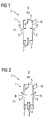
- FIG. 1 shows the scheme of the inventive fuel distributor 1 applied in a diffusion flame burner 2.
- the fuel distributor 1 comprises a distribution element 18 defining a cavity 3 with an inlet opening 4, an outlet opening 5, opposing the inlet opening 4, and two third openings 6.
- the third openings 6 are larger than the outlet opening 5.
- a restrictor 7 is arranged upstream the inlet opening 4 relative to the fuel flow 8, and sized to give the correct pressure to balance the fuel flows 8 between the outlet opening 5 and the third openings 6.
- Pressure P1 at the third openings 6 is greater than pressure P2 at the outlet opening 5.
- the majority of the fuel 8 will enter the combustion chamber 9 through the outlet opening 5.
- air 10 may enter the cavity 3 through third openings 6 and give some premixing of the fuel 8 and air 10.
- the pressure in the cavity 3 increases.
- P1 fuel 8 will spill out of the third openings 6, as shown in Figure 2 , and mix with air 10.
- the fuel/air premix will then enter the combustion chamber 9.
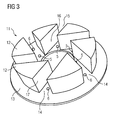
- the swirler 11 for a gas turbine engine is shown.
- the swirler 11 comprises swirler vanes 12 arranged on a swirler vane support 13.
- the swirler vanes 12 can be fixed to a burner head (not shown) with their sides showing away from the swirler vane support 13.
- swirler passages 14 are formed between a swirler passage inlet opening 15 and a swirler passage outlet opening 16.
- the swirler passages 14 are delimited by opposing side faces 16 of swirler vanes 12, by the surface of the swirler vane support 13 which shows to the burner head (not shown) and by a surface of the burner head to which the swirler vanes 12 are fixed.
- Outlet openings 5 and third openings 6 are arranged in the swirler passages 14 in the swirler vane support 13.
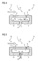
- FIG. 4 a cross-sectional view of an inventive fuel distributor 1 arranged in a swirler vane support 13 is shown.
- the outlet opening 5 and the third opening 6 open out into a swirler passage 14.
- Compressor air 10 is entering the swirler passage 14 from the left by the swirler passage inlet opening 15, where the pressure P1 exceeds the pressure P2 at the swirler passage outlet opening 16.
- Figure 4 shows the fuel distributor at low loads.
- Fuel 8 enters the cavity 3 of the fuel distributor 1 by the inlet opening 4 through the restrictor 7.
- a predominant proportion of the fuel 8 enters the swirler passage 14 through the outlet opening 5. Only a small amount of fuel 8 enters the swirler passage 14 through the third opening 6. This is beneficial for providing pilot fuel to the outlet opening 5.
- At very low load a part of the compressor air 10 entering the swirler passage 14 flows into the cavity 3 through the third opening 6, leading to some premixing in the cavity 3.
- Figures 6 and 7 show an alternative arrangement where the distribution of the fuel flow 8 across the height of the swirler passage 14 could be varied.
- the cavity 3 of the fuel distributor 1 is again arranged in the swirler vane support 13.
- the outlet opening 5 and the third opening 6 are arranged at different heights of the swirler vane 12 in the swirler passage 14.
- the outlet opening 5 has a smaller cross-sectional area and is arranged close to the swirler passage outlet opening 16, where the pressure is low
- the third opening 6 has a larger cross-sectional area and is arranged close to the swirler passage inlet opening 15, where the pressure is higher than at the swirler passage outlet opening 16.
- Figure 9 shows a further embodiment of the inventive fuel distributor 1.
- the general layout is similar to the embodiment described in Figure 6 .
- the pressure drop of the air 10 in the swirler passage 14 between the outlet opening 5 and the third opening 6 is varied by making the swirler passage 14 convergent (as shown in Figure 9 ) or divergent (not shown).
Abstract
Description
- The invention relates to a fuel distributor, in particular for a burner and a swirler.
- The main purpose of the burner is to mix fuel and air together to obtain stable and efficient combustion with good flame stability and the smallest possible amount of NOx emissions. Therefore, the burner design must ensure that the proper amounts of fuel and air are introduced in the right locations within the burner and that these amounts of fuel and air are thoroughly mixed, so that complete combustion takes place with a minimum amount of excess air in order to achieve optimum overall efficiency.
- The two burner principles, which could be combined to use their respective advantages, are the premix combustion burner and the diffusion flame burner.
- In the premix combustion burner, the air, required for combustion, is mixed with the burner fuel before delivery to the combustion zone. The better the mixing of fuel and air the less hot zones with a fuel/air ratio exceeding the stoichiometric requirements exist. Since flame temperature is the dominant factor driving NOx production it follows that the more fuel lean the mixture, the lower the NOx produced.
- In the diffusion flame burner, the fuel is not mixed with the air ahead of the combustion zone, but delivered as pure fuel in the immediate vicinity of the combustion zone. Diffusion flame burners provide good flame stability. The NOx production is relatively high.
- Low emission gas turbine engines often use a combustor with two operating modes including a pilot nozzle that forms a diffusion flame and a plurality of main nozzles for discharging a fuel/air mixture to form premixed flames as the main combustion around the diffusion flame. The
US 5,901,555 describes a conventional gas turbine with the main burners divided into a plurality of groups in accordance with the load. The flow rate of the pilot fuel is increased when the gas turbine load is low, to achieve stable combustion. When the gas turbine load is high, the ratio of the pilot fuel is decreased, to decrease the amount of NOx. Separately controllable fuel lines, valves, pipe work and a control logic are required to achieve the appropriate fuel flows to the pilot and main nozzles, increasing the cost of the engine. - The
EP 0936406 discloses another gas turbine burner provided with a swirler. The swirler comprises a swirler vane support, a plurality of swirler vanes arranged on the swirler vane support, a plurality of swirler passages formed by the swirler vanes and the swirler vane support, a plurality of fuel distributors, each of them comprising a distribution element, inlet openings, a plurality of outlet openings and a plurality of third outlet openings, wherein the third openings are arranged in an upstream section of the respective swirler passage and the outlet openings are arranged in a downstream section of the respective swirler passage, and wherein the cross section of the third openings is larger than the cross-section of the openings. - An object of the invention is to provide an improved fuel distributor.
- This object is achieved by the claims. The dependent claims describe advantageous developments and modifications of the invention.
- An inventive fuel distributor uses the pressure gradient across the combustion system to control the proportion of fuel provided to different areas of the combustion system. These areas could provide pilot fuel at low loads, or better mixing of the fuel and air at high loads.
- The system comprises a cavity with an inlet opening and at least two fuel injection openings. The fuel distributor relies on having a larger injection opening arranged in the cavity of the fuel distributor in an upstream section, relative to the flow of compressor air, and a smaller injection opening arranged in the cavity in a downstream section, relative to the flow of compressor air, and serving as feed near combustor pressure.
- In an advantageous embodiment of the invention a restrictor is arranged at the inlet opening to balance between the fuel flows through the at least one smaller outlet opening and the at least one larger third opening, respectively.
- In a further advantageous embodiment, the restrictor is adjustable to adapt the pressure for different fuel types.
- Since at low fuel pressure fuel basically leaves the distributor at the outlet opening that is exposed to the lowest external air pressure, it is advantageous to use this outlet opening as pilot fuel injection opening.
- For the same reason, it is advantageous to use the third opening with a larger cross-sectional area and exposed to higher external air pressure as main fuel injection opening.
- In an advantageous embodiment the principle of the fuel distributor is applied to a diffusion flame burner, where the fuel distributor has a tubular form with the outlet opening at the end of the tube facing the combustion chamber and with third openings arranged upstream the tube, relative to the flow of the fuel. At low fuel flows, the majority of the fuel will enter the combustion chamber through the outlet opening. Compressor air can enter the fuel distributor through the third openings and give some premixing of the fuel and the air. As the fuel flow increases, the pressure in the cavity increases and fuel will spill out through the third openings and will mix with compressor air and enter the combustion chamber.
- In another advantageous embodiment, the principle of the fuel distributor is applied to a swirler. The cavity of the fuel distributor is arranged in the base plate of the swirler. The fuel openings and the third openings are arranged in the mixing ducts, that is, in the passages of the swirler. The openings may be arranged in the base plate of the swirler or in the swirler vanes. If arranged in the swirler vanes, the arrangement could be at different heights to improve the fuel distribution over the swirler vane height. Smaller fuel outlet openings would be closer to the swirler exit hole with lower pressure. Larger third openings would rather be in an upstream part of the swirler passages relative to the flow of compressor air, with higher pressure. The fuel outlet openings would serve as pilot and the third openings as main fuel injection openings.
- In yet another advantageous embodiment, the pressure drop of the air between an outlet opening and a third opening in a mixing duct or a swirler passage is controlled by making the mixing duct or swirler passage convergent or divergent.
- With such a design of the fuel distribution system emissions of NOx are reduced. The inventive fuel distributor provides an increasing level of premix as the fuel flow increases. The inventive fuel distributor even provides some premixing of fuel and air at low flows, thus further reducing NOx emissions. Furthermore, the fuel/air mixing within a premix duct like e.g. a swirler passage can be varied as the fuel flow changes without the use of control valves, thus reducing costs and increasing reliability.
- The invention will now be further described with reference to the accompanying drawings in which:
- Figure 1
- represents an inventive diffusion flame burner at low fuel flow,
- Figure 2
- represents an inventive diffusion flame burner at high fuel flow,
- Figure 3
- represents a swirler,
- Figure 4
- represents a fuel distributor arranged in a swirler base plate with openings in the swirler base plate at low fuel flow,
- Figure 5
- represents a fuel distributor arranged in a swirler base plate with openings in the swirler base plate at high fuel flow,
- Figure 6
- represents a fuel distributor arranged in a swirler base plate with openings in the side face of a swirler vane,
- Figure 7
- shows a swirler vane corresponding to the fuel distributor of
Figure 7 , - Figure 8
- shows the percentage of mass flow through the fuel injection openings as a function of the fuel mass flow, and
- Figure 9
- represents a fuel distributor arranged in a swirler base plate with openings in the side face of a swirler vane and converging swirler passage.
- In the drawings like references identify like or equivalent parts.
-
Figure 1 shows the scheme of the inventive fuel distributor 1 applied in adiffusion flame burner 2. The fuel distributor 1 comprises adistribution element 18 defining acavity 3 with aninlet opening 4, anoutlet opening 5, opposing theinlet opening 4, and twothird openings 6. Thethird openings 6 are larger than theoutlet opening 5. Arestrictor 7 is arranged upstream theinlet opening 4 relative to thefuel flow 8, and sized to give the correct pressure to balance the fuel flows 8 between theoutlet opening 5 and thethird openings 6. Pressure P1 at thethird openings 6 is greater than pressure P2 at theoutlet opening 5. At low fuel flows 8, the majority of thefuel 8 will enter thecombustion chamber 9 through theoutlet opening 5. If thefuel flow 8 is low enough,air 10 may enter thecavity 3 throughthird openings 6 and give some premixing of thefuel 8 andair 10. As thefuel flow 8 increases, the pressure in thecavity 3 increases. When the pressure in thecavity 3 is higher than P1,fuel 8 will spill out of thethird openings 6, as shown inFigure 2 , and mix withair 10. The fuel/air premix will then enter thecombustion chamber 9. - Referring to
Figure 3 aswirler 11 for a gas turbine engine is shown. Theswirler 11 comprisesswirler vanes 12 arranged on aswirler vane support 13. The swirler vanes 12 can be fixed to a burner head (not shown) with their sides showing away from theswirler vane support 13. Between neighbouringswirler vanes 12swirler passages 14 are formed. Theswirler passages 14 extend between a swirlerpassage inlet opening 15 and a swirlerpassage outlet opening 16. Theswirler passages 14 are delimited by opposing side faces 16 ofswirler vanes 12, by the surface of theswirler vane support 13 which shows to the burner head (not shown) and by a surface of the burner head to which theswirler vanes 12 are fixed.Outlet openings 5 andthird openings 6 are arranged in theswirler passages 14 in theswirler vane support 13. - Referring to
Figures 4 and 5 a cross-sectional view of an inventive fuel distributor 1 arranged in aswirler vane support 13 is shown. Theoutlet opening 5 and thethird opening 6 open out into aswirler passage 14.Compressor air 10 is entering theswirler passage 14 from the left by the swirlerpassage inlet opening 15, where the pressure P1 exceeds the pressure P2 at the swirlerpassage outlet opening 16.Figure 4 shows the fuel distributor at low loads.Fuel 8 enters thecavity 3 of the fuel distributor 1 by theinlet opening 4 through therestrictor 7. A predominant proportion of thefuel 8 enters theswirler passage 14 through theoutlet opening 5. Only a small amount offuel 8 enters theswirler passage 14 through thethird opening 6. This is beneficial for providing pilot fuel to theoutlet opening 5. At very low load a part of thecompressor air 10 entering theswirler passage 14 flows into thecavity 3 through thethird opening 6, leading to some premixing in thecavity 3. - At high loads the proportion of
fuel 8 entering theswirler passage 14 through thethird opening 6 is increased, as shown inFigure 5 . The fuel pressure in thecavity 3 overcomes the pressure at the swirlerpassage inlet opening 15 andfuel 8 spills out into theswirler passage 14 mainly through thethird opening 6 with the larger cross-sectional area. -
Figures 6 and 7 show an alternative arrangement where the distribution of thefuel flow 8 across the height of theswirler passage 14 could be varied. Thecavity 3 of the fuel distributor 1 is again arranged in theswirler vane support 13. Theoutlet opening 5 and thethird opening 6 are arranged at different heights of theswirler vane 12 in theswirler passage 14. Again, theoutlet opening 5 has a smaller cross-sectional area and is arranged close to the swirlerpassage outlet opening 16, where the pressure is low and thethird opening 6 has a larger cross-sectional area and is arranged close to the swirlerpassage inlet opening 15, where the pressure is higher than at the swirlerpassage outlet opening 16. - Referring to
Figure 8 the percentage of fuel mass flow through theoutlet opening 5 and thethird opening 6 as a function of the total fuel mass flow is shown. At low load, i.e. at low mass flow, fuel mainly flows through theoutlet opening 5. The higher the fuel mass flow the higher the percentage of fuel flowing through thethird opening 6. -
Figure 9 shows a further embodiment of the inventive fuel distributor 1. The general layout is similar to the embodiment described inFigure 6 . The pressure drop of theair 10 in theswirler passage 14 between theoutlet opening 5 and thethird opening 6 is varied by making theswirler passage 14 convergent (as shown inFigure 9 ) or divergent (not shown).
Claims (13)
- A swirler (11), comprising:a swirler vane support (13);a plurality of swirler vanes (12) arranged on the swirler vane support (13);a plurality of swirler passages (14) formed by the swirler vanes (12) and the swirler vane support (13); anda plurality of fuel distributors (1), each of the fuel distributors (1), comprisingwherein the cavities (3) of the plurality of fuel distributors (1) are arranged in the swirler vane support (13).- a distribution element (18) defining a cavity (3),- whereby the cavity (3) has an inlet opening (4), at least one outlet opening (5) and at least one third opening (6),- whereby the at least one third opening (6) is arranged in the cavity (3) of the fuel distributor (1) in an upstream section of a respective swirler passage (14), and the at least one outlet opening (5) is arranged in the cavity (3) in a downstream section of the respective swirler passage (14), and- whereby the cross-section of the at least one third opening (6) is larger than the cross-section of the at least one outlet opening (5),
- A swirler (11) as claimed in claim 1, wherein a restrictor (7) is arranged upstream the inlet opening (4) of a respective fuel distributor (1), relative to the fuel flow (8), the restrictor (7) being sized and configured to balance between the fuel flows (8) through the at least one outlet opening (5) and the at least one third opening (6), respectively.
- A swirler (11) as claimed in claim 2, wherein the restrictor (7) of a respective fuel distributor (1) is adjustable.
- A swirler (11) as claimed any of the preceding claims, wherein the at least one outlet opening (5) of a respective fuel distributor (1) is a pilot fuel injection opening.
- A swirler (11) as claimed in any of the preceding claims, wherein the at least one third opening (6) of a respective fuel distributor (1) is a main fuel injection opening.
- A swirler (11) as claimed in any of the preceding claims, wherein the outlet openings (5) and the third openings (6) of the plurality of fuel distributors (1) are arranged in the swirler passages (14).
- A swirler (11) as claimed in any of the preceding claims, wherein the outlet openings (5) of the plurality of fuel distributors (1) are arranged at a downstream end of the swirler passages (14) relative to the flow of compressor air (10).
- A swirler (11) as claimed in any of the preceding claims, wherein the third openings (6) of the plurality of fuel distributors (1) are arranged at an upstream end of the swirler passages (14) relative to the flow of compressor air (10).
- A swirler (11) as claimed in any of the preceding claims, wherein the outlet openings (5) and the third openings (6) of the plurality of fuel distributors (1) are arranged in the swirler vanes support (13).
- A swirler (11) as claimed in any of the preceding claims, wherein the outlet openings (5) and the third openings (6) of the plurality of fuel distributors (1) are arranged in the swirler vanes (12).
- A swirler (11) as claimed in claim 10, wherein the outlet openings (5) and the third openings (6) of the plurality of fuel distributors (1) are arranged at different heights of the swirler vanes (12).
- A swirler (11) as claimed in any of the preceding claims, wherein a cross-sectional area of the swirler passages (14) increases in a downstream direction relative to the flow of compressor air (10).
- A swirler (11) as claimed in any of claims 1 to 11, wherein a cross-sectional area of the swirler passages (14) decreases in a downstream direction relative to the flow of compressor air (10).
Priority Applications (1)
| Application Number | Priority Date | Filing Date | Title |
|---|---|---|---|
| EP08750236A EP2147256B1 (en) | 2007-05-18 | 2008-05-09 | Fuel distributor |
Applications Claiming Priority (3)
| Application Number | Priority Date | Filing Date | Title |
|---|---|---|---|
| EP07009960A EP1992878A1 (en) | 2007-05-18 | 2007-05-18 | Fuel distributor |
| EP08750236A EP2147256B1 (en) | 2007-05-18 | 2008-05-09 | Fuel distributor |
| PCT/EP2008/055762 WO2008141955A1 (en) | 2007-05-18 | 2008-05-09 | Fuel distributor |
Publications (2)
| Publication Number | Publication Date |
|---|---|
| EP2147256A1 EP2147256A1 (en) | 2010-01-27 |
| EP2147256B1 true EP2147256B1 (en) | 2012-03-14 |
Family
ID=38573478
Family Applications (2)
| Application Number | Title | Priority Date | Filing Date |
|---|---|---|---|
| EP07009960A Withdrawn EP1992878A1 (en) | 2007-05-18 | 2007-05-18 | Fuel distributor |
| EP08750236A Not-in-force EP2147256B1 (en) | 2007-05-18 | 2008-05-09 | Fuel distributor |
Family Applications Before (1)
| Application Number | Title | Priority Date | Filing Date |
|---|---|---|---|
| EP07009960A Withdrawn EP1992878A1 (en) | 2007-05-18 | 2007-05-18 | Fuel distributor |
Country Status (5)
| Country | Link |
|---|---|
| EP (2) | EP1992878A1 (en) |
| CN (1) | CN101688669B (en) |
| AT (1) | ATE549582T1 (en) |
| RU (1) | RU2470228C2 (en) |
| WO (1) | WO2008141955A1 (en) |
Families Citing this family (4)
| Publication number | Priority date | Publication date | Assignee | Title |
|---|---|---|---|---|
| ATE540265T1 (en) * | 2009-04-06 | 2012-01-15 | Siemens Ag | SWIRL DEVICE, COMBUSTION CHAMBER AND GAS TURBINE WITH IMPROVED SWIRL |
| EP2246617B1 (en) | 2009-04-29 | 2017-04-19 | Siemens Aktiengesellschaft | A burner for a gas turbine engine |
| DE102009045950A1 (en) | 2009-10-23 | 2011-04-28 | Man Diesel & Turbo Se | swirl generator |
| EP2942563A1 (en) * | 2014-05-09 | 2015-11-11 | Siemens Aktiengesellschaft | Swirler for a burner of a gas turbine engine, burner of a gas turbine engine and gas turbine engine |
Family Cites Families (7)
| Publication number | Priority date | Publication date | Assignee | Title |
|---|---|---|---|---|
| RU2122684C1 (en) * | 1994-09-29 | 1998-11-27 | Акционерное общество открытого типа "Экотеплогаз" | Method for fossil fuel combustion in combustion chamber of gas-turbine plant or in other fuel- combustion facility |
| FR2753779B1 (en) * | 1996-09-26 | 1998-10-16 | AERODYNAMIC INJECTION SYSTEM FOR A FUEL AIR MIXTURE | |
| GB2324147B (en) * | 1997-04-10 | 2001-09-05 | Europ Gas Turbines Ltd | Fuel-injection arrangement for a gas turbine combuster |
| DE69916911T2 (en) * | 1998-02-10 | 2005-04-21 | Gen Electric | Burner with uniform fuel / air premix for low-emission combustion |
| EP1394471A1 (en) * | 2002-09-02 | 2004-03-03 | Siemens Aktiengesellschaft | Burner |
| EP1507119A1 (en) * | 2003-08-13 | 2005-02-16 | Siemens Aktiengesellschaft | Burner and process to operate a gas turbine |
| RU2260747C2 (en) * | 2003-11-18 | 2005-09-20 | Открытое акционерное общество "Авиадвигатель" | Combustion chamber of gas-turbine plant |
-
2007
- 2007-05-18 EP EP07009960A patent/EP1992878A1/en not_active Withdrawn
-
2008
- 2008-05-09 EP EP08750236A patent/EP2147256B1/en not_active Not-in-force
- 2008-05-09 WO PCT/EP2008/055762 patent/WO2008141955A1/en active Application Filing
- 2008-05-09 CN CN2008800165789A patent/CN101688669B/en not_active Expired - Fee Related
- 2008-05-09 RU RU2009147021/06A patent/RU2470228C2/en not_active IP Right Cessation
- 2008-05-09 AT AT08750236T patent/ATE549582T1/en active
Also Published As
| Publication number | Publication date |
|---|---|
| ATE549582T1 (en) | 2012-03-15 |
| EP2147256A1 (en) | 2010-01-27 |
| CN101688669B (en) | 2011-06-08 |
| RU2470228C2 (en) | 2012-12-20 |
| CN101688669A (en) | 2010-03-31 |
| EP1992878A1 (en) | 2008-11-19 |
| WO2008141955A1 (en) | 2008-11-27 |
| RU2009147021A (en) | 2011-06-27 |
Similar Documents
| Publication | Publication Date | Title |
|---|---|---|
| US8769955B2 (en) | Self-regulating fuel staging port for turbine combustor | |
| US6832481B2 (en) | Turbine engine fuel nozzle | |
| EP2522911B1 (en) | Burner with a lobed swirler | |
| US7509811B2 (en) | Multi-point staging strategy for low emission and stable combustion | |
| US8316644B2 (en) | Burner having swirler with corrugated downstream wall sections | |
| US5319935A (en) | Staged gas turbine combustion chamber with counter swirling arrays of radial vanes having interjacent fuel injection | |
| US8371125B2 (en) | Burner and gas turbine combustor | |
| EP2496884B1 (en) | Reheat burner injection system | |
| US5640851A (en) | Gas turbine engine combustion chamber | |
| EP0554325B1 (en) | Gasturbine combustion chamber and method of operation thereof | |
| EP1426689B1 (en) | Gas turbine combustor having staged burners with dissimilar mixing passage geometries | |
| EP2427696B1 (en) | Swirler, combustion chamber, and gas turbine with improved mixing | |
| EP2218966B1 (en) | Fuel injection for gas turbine combustors | |
| US20100223932A1 (en) | Gas Turbine Burner and Method of Mixing Fuel and Air in a Swirling Area of a Gas Turbine Burner | |
| EP2873922B1 (en) | Gas turbine combustor | |
| US6327860B1 (en) | Fuel injector for low emissions premixing gas turbine combustor | |
| EP2147256B1 (en) | Fuel distributor | |
| US9016601B2 (en) | Fuel distributor | |
| EP1921376A1 (en) | Fuel injection system | |
| EP0852687B1 (en) | Fuel injector arrangement for a combustion apparatus | |
| US20190301369A1 (en) | A method of holding flame with no combustion instability, low pollutant emissions, least pressure drop and flame temperature in a gas turbine combustor and a gas turbine combustor to perform the method | |
| EP1531305A1 (en) | Multi-point fuel injector | |
| CN116379472A (en) | Burner assembly with in-line injector | |
| CN113776086A (en) | Low-pollution combustion chamber nozzle structure and method |
Legal Events
| Date | Code | Title | Description |
|---|---|---|---|
| PUAI | Public reference made under article 153(3) epc to a published international application that has entered the european phase |
Free format text: ORIGINAL CODE: 0009012 |
|
| 17P | Request for examination filed |
Effective date: 20090916 |
|
| AK | Designated contracting states |
Kind code of ref document: A1 Designated state(s): AT BE BG CH CY CZ DE DK EE ES FI FR GB GR HR HU IE IS IT LI LT LU LV MC MT NL NO PL PT RO SE SI SK TR |
|
| AX | Request for extension of the european patent |
Extension state: AL BA MK RS |
|
| DAX | Request for extension of the european patent (deleted) | ||
| GRAP | Despatch of communication of intention to grant a patent |
Free format text: ORIGINAL CODE: EPIDOSNIGR1 |
|
| GRAS | Grant fee paid |
Free format text: ORIGINAL CODE: EPIDOSNIGR3 |
|
| GRAA | (expected) grant |
Free format text: ORIGINAL CODE: 0009210 |
|
| AK | Designated contracting states |
Kind code of ref document: B1 Designated state(s): AT BE BG CH CY CZ DE DK EE ES FI FR GB GR HR HU IE IS IT LI LT LU LV MC MT NL NO PL PT RO SE SI SK TR |
|
| REG | Reference to a national code |
Ref country code: GB Ref legal event code: FG4D |
|
| REG | Reference to a national code |
Ref country code: AT Ref legal event code: REF Ref document number: 549582 Country of ref document: AT Kind code of ref document: T Effective date: 20120315 Ref country code: CH Ref legal event code: NV Representative=s name: SIEMENS SCHWEIZ AG Ref country code: CH Ref legal event code: EP |
|
| REG | Reference to a national code |
Ref country code: IE Ref legal event code: FG4D |
|
| REG | Reference to a national code |
Ref country code: DE Ref legal event code: R096 Ref document number: 602008014121 Country of ref document: DE Effective date: 20120510 |
|
| REG | Reference to a national code |
Ref country code: NL Ref legal event code: VDEP Effective date: 20120314 |
|
| PG25 | Lapsed in a contracting state [announced via postgrant information from national office to epo] |
Ref country code: LT Free format text: LAPSE BECAUSE OF FAILURE TO SUBMIT A TRANSLATION OF THE DESCRIPTION OR TO PAY THE FEE WITHIN THE PRESCRIBED TIME-LIMIT Effective date: 20120314 Ref country code: HR Free format text: LAPSE BECAUSE OF FAILURE TO SUBMIT A TRANSLATION OF THE DESCRIPTION OR TO PAY THE FEE WITHIN THE PRESCRIBED TIME-LIMIT Effective date: 20120314 Ref country code: NO Free format text: LAPSE BECAUSE OF FAILURE TO SUBMIT A TRANSLATION OF THE DESCRIPTION OR TO PAY THE FEE WITHIN THE PRESCRIBED TIME-LIMIT Effective date: 20120614 |
|
| LTIE | Lt: invalidation of european patent or patent extension |
Effective date: 20120314 |
|
| PG25 | Lapsed in a contracting state [announced via postgrant information from national office to epo] |
Ref country code: GR Free format text: LAPSE BECAUSE OF FAILURE TO SUBMIT A TRANSLATION OF THE DESCRIPTION OR TO PAY THE FEE WITHIN THE PRESCRIBED TIME-LIMIT Effective date: 20120615 Ref country code: FI Free format text: LAPSE BECAUSE OF FAILURE TO SUBMIT A TRANSLATION OF THE DESCRIPTION OR TO PAY THE FEE WITHIN THE PRESCRIBED TIME-LIMIT Effective date: 20120314 Ref country code: LV Free format text: LAPSE BECAUSE OF FAILURE TO SUBMIT A TRANSLATION OF THE DESCRIPTION OR TO PAY THE FEE WITHIN THE PRESCRIBED TIME-LIMIT Effective date: 20120314 |
|
| REG | Reference to a national code |
Ref country code: AT Ref legal event code: MK05 Ref document number: 549582 Country of ref document: AT Kind code of ref document: T Effective date: 20120314 |
|
| PG25 | Lapsed in a contracting state [announced via postgrant information from national office to epo] |
Ref country code: CY Free format text: LAPSE BECAUSE OF FAILURE TO SUBMIT A TRANSLATION OF THE DESCRIPTION OR TO PAY THE FEE WITHIN THE PRESCRIBED TIME-LIMIT Effective date: 20120314 |
|
| PG25 | Lapsed in a contracting state [announced via postgrant information from national office to epo] |
Ref country code: PL Free format text: LAPSE BECAUSE OF FAILURE TO SUBMIT A TRANSLATION OF THE DESCRIPTION OR TO PAY THE FEE WITHIN THE PRESCRIBED TIME-LIMIT Effective date: 20120314 Ref country code: BE Free format text: LAPSE BECAUSE OF FAILURE TO SUBMIT A TRANSLATION OF THE DESCRIPTION OR TO PAY THE FEE WITHIN THE PRESCRIBED TIME-LIMIT Effective date: 20120314 Ref country code: RO Free format text: LAPSE BECAUSE OF FAILURE TO SUBMIT A TRANSLATION OF THE DESCRIPTION OR TO PAY THE FEE WITHIN THE PRESCRIBED TIME-LIMIT Effective date: 20120314 Ref country code: IS Free format text: LAPSE BECAUSE OF FAILURE TO SUBMIT A TRANSLATION OF THE DESCRIPTION OR TO PAY THE FEE WITHIN THE PRESCRIBED TIME-LIMIT Effective date: 20120714 Ref country code: SE Free format text: LAPSE BECAUSE OF FAILURE TO SUBMIT A TRANSLATION OF THE DESCRIPTION OR TO PAY THE FEE WITHIN THE PRESCRIBED TIME-LIMIT Effective date: 20120314 Ref country code: SI Free format text: LAPSE BECAUSE OF FAILURE TO SUBMIT A TRANSLATION OF THE DESCRIPTION OR TO PAY THE FEE WITHIN THE PRESCRIBED TIME-LIMIT Effective date: 20120314 Ref country code: CZ Free format text: LAPSE BECAUSE OF FAILURE TO SUBMIT A TRANSLATION OF THE DESCRIPTION OR TO PAY THE FEE WITHIN THE PRESCRIBED TIME-LIMIT Effective date: 20120314 Ref country code: EE Free format text: LAPSE BECAUSE OF FAILURE TO SUBMIT A TRANSLATION OF THE DESCRIPTION OR TO PAY THE FEE WITHIN THE PRESCRIBED TIME-LIMIT Effective date: 20120314 |
|
| PG25 | Lapsed in a contracting state [announced via postgrant information from national office to epo] |
Ref country code: PT Free format text: LAPSE BECAUSE OF FAILURE TO SUBMIT A TRANSLATION OF THE DESCRIPTION OR TO PAY THE FEE WITHIN THE PRESCRIBED TIME-LIMIT Effective date: 20120716 Ref country code: SK Free format text: LAPSE BECAUSE OF FAILURE TO SUBMIT A TRANSLATION OF THE DESCRIPTION OR TO PAY THE FEE WITHIN THE PRESCRIBED TIME-LIMIT Effective date: 20120314 |
|
| PG25 | Lapsed in a contracting state [announced via postgrant information from national office to epo] |
Ref country code: MC Free format text: LAPSE BECAUSE OF NON-PAYMENT OF DUE FEES Effective date: 20120531 |
|
| PLBE | No opposition filed within time limit |
Free format text: ORIGINAL CODE: 0009261 |
|
| STAA | Information on the status of an ep patent application or granted ep patent |
Free format text: STATUS: NO OPPOSITION FILED WITHIN TIME LIMIT |
|
| PG25 | Lapsed in a contracting state [announced via postgrant information from national office to epo] |
Ref country code: NL Free format text: LAPSE BECAUSE OF FAILURE TO SUBMIT A TRANSLATION OF THE DESCRIPTION OR TO PAY THE FEE WITHIN THE PRESCRIBED TIME-LIMIT Effective date: 20120314 Ref country code: AT Free format text: LAPSE BECAUSE OF FAILURE TO SUBMIT A TRANSLATION OF THE DESCRIPTION OR TO PAY THE FEE WITHIN THE PRESCRIBED TIME-LIMIT Effective date: 20120314 Ref country code: DK Free format text: LAPSE BECAUSE OF FAILURE TO SUBMIT A TRANSLATION OF THE DESCRIPTION OR TO PAY THE FEE WITHIN THE PRESCRIBED TIME-LIMIT Effective date: 20120314 |
|
| 26N | No opposition filed |
Effective date: 20121217 |
|
| REG | Reference to a national code |
Ref country code: IE Ref legal event code: MM4A |
|
| REG | Reference to a national code |
Ref country code: DE Ref legal event code: R097 Ref document number: 602008014121 Country of ref document: DE Effective date: 20121217 |
|
| PG25 | Lapsed in a contracting state [announced via postgrant information from national office to epo] |
Ref country code: ES Free format text: LAPSE BECAUSE OF FAILURE TO SUBMIT A TRANSLATION OF THE DESCRIPTION OR TO PAY THE FEE WITHIN THE PRESCRIBED TIME-LIMIT Effective date: 20120625 Ref country code: IE Free format text: LAPSE BECAUSE OF NON-PAYMENT OF DUE FEES Effective date: 20120509 |
|
| PG25 | Lapsed in a contracting state [announced via postgrant information from national office to epo] |
Ref country code: BG Free format text: LAPSE BECAUSE OF FAILURE TO SUBMIT A TRANSLATION OF THE DESCRIPTION OR TO PAY THE FEE WITHIN THE PRESCRIBED TIME-LIMIT Effective date: 20120614 Ref country code: MT Free format text: LAPSE BECAUSE OF FAILURE TO SUBMIT A TRANSLATION OF THE DESCRIPTION OR TO PAY THE FEE WITHIN THE PRESCRIBED TIME-LIMIT Effective date: 20120314 |
|
| PG25 | Lapsed in a contracting state [announced via postgrant information from national office to epo] |
Ref country code: TR Free format text: LAPSE BECAUSE OF FAILURE TO SUBMIT A TRANSLATION OF THE DESCRIPTION OR TO PAY THE FEE WITHIN THE PRESCRIBED TIME-LIMIT Effective date: 20120314 |
|
| PG25 | Lapsed in a contracting state [announced via postgrant information from national office to epo] |
Ref country code: LU Free format text: LAPSE BECAUSE OF NON-PAYMENT OF DUE FEES Effective date: 20120509 |
|
| PG25 | Lapsed in a contracting state [announced via postgrant information from national office to epo] |
Ref country code: HU Free format text: LAPSE BECAUSE OF FAILURE TO SUBMIT A TRANSLATION OF THE DESCRIPTION OR TO PAY THE FEE WITHIN THE PRESCRIBED TIME-LIMIT Effective date: 20080509 |
|
| PGFP | Annual fee paid to national office [announced via postgrant information from national office to epo] |
Ref country code: CH Payment date: 20150803 Year of fee payment: 8 Ref country code: DE Payment date: 20150720 Year of fee payment: 8 |
|
| REG | Reference to a national code |
Ref country code: FR Ref legal event code: PLFP Year of fee payment: 9 |
|
| PGFP | Annual fee paid to national office [announced via postgrant information from national office to epo] |
Ref country code: GB Payment date: 20160512 Year of fee payment: 9 |
|
| PGFP | Annual fee paid to national office [announced via postgrant information from national office to epo] |
Ref country code: IT Payment date: 20160527 Year of fee payment: 9 Ref country code: FR Payment date: 20160512 Year of fee payment: 9 |
|
| REG | Reference to a national code |
Ref country code: DE Ref legal event code: R119 Ref document number: 602008014121 Country of ref document: DE |
|
| REG | Reference to a national code |
Ref country code: CH Ref legal event code: PL |
|
| PG25 | Lapsed in a contracting state [announced via postgrant information from national office to epo] |
Ref country code: CH Free format text: LAPSE BECAUSE OF NON-PAYMENT OF DUE FEES Effective date: 20160531 Ref country code: LI Free format text: LAPSE BECAUSE OF NON-PAYMENT OF DUE FEES Effective date: 20160531 |
|
| PG25 | Lapsed in a contracting state [announced via postgrant information from national office to epo] |
Ref country code: DE Free format text: LAPSE BECAUSE OF NON-PAYMENT OF DUE FEES Effective date: 20161201 |
|
| GBPC | Gb: european patent ceased through non-payment of renewal fee |
Effective date: 20170509 |
|
| REG | Reference to a national code |
Ref country code: FR Ref legal event code: ST Effective date: 20180131 |
|
| PG25 | Lapsed in a contracting state [announced via postgrant information from national office to epo] |
Ref country code: GB Free format text: LAPSE BECAUSE OF NON-PAYMENT OF DUE FEES Effective date: 20170509 |
|
| PG25 | Lapsed in a contracting state [announced via postgrant information from national office to epo] |
Ref country code: IT Free format text: LAPSE BECAUSE OF NON-PAYMENT OF DUE FEES Effective date: 20170509 Ref country code: FR Free format text: LAPSE BECAUSE OF NON-PAYMENT OF DUE FEES Effective date: 20170531 |