EP2146917B1 - Method for selective folding or redirecting of cut web products - Google Patents
Method for selective folding or redirecting of cut web products Download PDFInfo
- Publication number
- EP2146917B1 EP2146917B1 EP08719714.1A EP08719714A EP2146917B1 EP 2146917 B1 EP2146917 B1 EP 2146917B1 EP 08719714 A EP08719714 A EP 08719714A EP 2146917 B1 EP2146917 B1 EP 2146917B1
- Authority
- EP
- European Patent Office
- Prior art keywords
- cut web
- folding mechanism
- web products
- folding
- pathway
- Prior art date
- Legal status (The legal status is an assumption and is not a legal conclusion. Google has not performed a legal analysis and makes no representation as to the accuracy of the status listed.)
- Revoked
Links
Images



Classifications
-
- B—PERFORMING OPERATIONS; TRANSPORTING
- B65—CONVEYING; PACKING; STORING; HANDLING THIN OR FILAMENTARY MATERIAL
- B65H—HANDLING THIN OR FILAMENTARY MATERIAL, e.g. SHEETS, WEBS, CABLES
- B65H29/00—Delivering or advancing articles from machines; Advancing articles to or into piles
- B65H29/58—Article switches or diverters
- B65H29/62—Article switches or diverters diverting faulty articles from the main streams
-
- A—HUMAN NECESSITIES
- A61—MEDICAL OR VETERINARY SCIENCE; HYGIENE
- A61F—FILTERS IMPLANTABLE INTO BLOOD VESSELS; PROSTHESES; DEVICES PROVIDING PATENCY TO, OR PREVENTING COLLAPSING OF, TUBULAR STRUCTURES OF THE BODY, e.g. STENTS; ORTHOPAEDIC, NURSING OR CONTRACEPTIVE DEVICES; FOMENTATION; TREATMENT OR PROTECTION OF EYES OR EARS; BANDAGES, DRESSINGS OR ABSORBENT PADS; FIRST-AID KITS
- A61F13/00—Bandages or dressings; Absorbent pads
- A61F13/15—Absorbent pads, e.g. sanitary towels, swabs or tampons for external or internal application to the body; Supporting or fastening means therefor; Tampon applicators
- A61F13/15577—Apparatus or processes for manufacturing
- A61F13/15707—Mechanical treatment, e.g. notching, twisting, compressing, shaping
- A61F13/15747—Folding; Pleating; Coiling; Stacking; Packaging
-
- B—PERFORMING OPERATIONS; TRANSPORTING
- B65—CONVEYING; PACKING; STORING; HANDLING THIN OR FILAMENTARY MATERIAL
- B65H—HANDLING THIN OR FILAMENTARY MATERIAL, e.g. SHEETS, WEBS, CABLES
- B65H29/00—Delivering or advancing articles from machines; Advancing articles to or into piles
- B65H29/58—Article switches or diverters
- B65H29/60—Article switches or diverters diverting the stream into alternative paths
-
- B—PERFORMING OPERATIONS; TRANSPORTING
- B65—CONVEYING; PACKING; STORING; HANDLING THIN OR FILAMENTARY MATERIAL
- B65H—HANDLING THIN OR FILAMENTARY MATERIAL, e.g. SHEETS, WEBS, CABLES
- B65H45/00—Folding thin material
- B65H45/02—Folding limp material without application of pressure to define or form crease lines
- B65H45/04—Folding sheets
-
- B—PERFORMING OPERATIONS; TRANSPORTING
- B65—CONVEYING; PACKING; STORING; HANDLING THIN OR FILAMENTARY MATERIAL
- B65H—HANDLING THIN OR FILAMENTARY MATERIAL, e.g. SHEETS, WEBS, CABLES
- B65H45/00—Folding thin material
- B65H45/12—Folding articles or webs with application of pressure to define or form crease lines
- B65H45/18—Oscillating or reciprocating blade folders
-
- B—PERFORMING OPERATIONS; TRANSPORTING
- B65—CONVEYING; PACKING; STORING; HANDLING THIN OR FILAMENTARY MATERIAL
- B65H—HANDLING THIN OR FILAMENTARY MATERIAL, e.g. SHEETS, WEBS, CABLES
- B65H2220/00—Function indicators
- B65H2220/09—Function indicators indicating that several of an entity are present
-
- B—PERFORMING OPERATIONS; TRANSPORTING
- B65—CONVEYING; PACKING; STORING; HANDLING THIN OR FILAMENTARY MATERIAL
- B65H—HANDLING THIN OR FILAMENTARY MATERIAL, e.g. SHEETS, WEBS, CABLES
- B65H2404/00—Parts for transporting or guiding the handled material
- B65H2404/60—Other elements in face contact with handled material
- B65H2404/67—Other elements in face contact with handled material rotating around an axis parallel to face of material and parallel to transport direction
-
- B—PERFORMING OPERATIONS; TRANSPORTING
- B65—CONVEYING; PACKING; STORING; HANDLING THIN OR FILAMENTARY MATERIAL
- B65H—HANDLING THIN OR FILAMENTARY MATERIAL, e.g. SHEETS, WEBS, CABLES
- B65H2701/00—Handled material; Storage means
- B65H2701/10—Handled articles or webs
- B65H2701/19—Specific article or web
- B65H2701/1924—Napkins or tissues, e.g. dressings, toweling, serviettes, kitchen paper and compresses
Definitions
- the present disclosure relates to a method for selective folding or redirecting of cut web products. More particularly, the present disclosure relates to a method for high speed selective folding, redirecting, and/or rejecting of cut web products, such as diapers or catamenials.
- some cut products manufactured on a high speed production line may contain defects.
- Several mechanisms exist for rejecting defective cut web products such as by diverting the defective cut web products from the stream of cut web products that are of satisfactory condition or good quality.
- One method that has been used to reject cut web products includes forcing the defective cut web products out of the stream of satisfactory products by using pneumatic air blasts, which divert the defective cut web products to a path that differs from that for the stream of satisfactory products. In such a method, the defective cut web products are detected, and a pneumatic air blast forces the defective cut web products out of the stream of quality products and into a reject gap provided in the conveyor system or production line.
- the reject gap will be provided prior to subjecting the cut web products to further processing, such as folding.
- Methods of rejecting cut web products using pneumatic air blasts involve several disadvantages. Devices creating pneumatic air blasts require space. Similarly, extra space along the conveyor system is required to include a reject gap. A reject gap further involves system reliability issues related to having a gap in the conveyor system, such as jamming. Additionally, pneumatic air blasts create excessive dust and noise. Furthermore, pneumatic air blasts are not entirely accurate and can divert more than solely the defective cut web product from the stream of satisfactory products. Also, the equipment to create, convey, regulate, and control the air blast is expensive to install and operate.
- a similar method of rejecting cut web products includes using a vacuum to remove the defective cut web products from the stream of quality products.
- a vacuum rather than pneumatic air blasts, involves similar disadvantages, such as requiring large amounts of space for the vacuum device, providing extra space along the conveyor system for the reject gap, creating excessive noise and dust, etc. Also, the additional vacuum equipment and vacuum creation, control, and transportation is expensive.
- Another method of rejecting cut web products includes mechanically activated switches, or flippers, that divert the defective cut web products to an alternative pathway, similar to the manner railway switches can divert trains to a different track.
- the mechanical switches are commonly activated via a pneumatic or hydraulic cylinder or via an electric motor.
- a typical configuration includes mechanical switches that pop up from the conveyor system and divert the defective cut web products below the switch towards an alternate pathway. Rejection of defective cut web products typically takes place before the cut web products are subjected to further processing, such as folding. As such, more space is required to create room for the mechanically activated switches and the alternate pathway. Thus, space consumption is a disadvantage to the mechanical switch method. Furthermore, the additional mechanical switch equipment is expensive.
- US 4,650,173, issued on March 17th 1987 relates to a method and apparatus for operating a diaper-producing machine where a series of unfolded diapers are advanced along a path containing a plurality of stackers each having a folding blade, the apparatus having means for periodically altering the movement of one blade to permit diaper movement past that stacker to a subsequent one, thereby continuing stacking while a previously completed stack is removed.
- a method and apparatus for high speed selective folding, redirecting, and/or rejecting of cut web products that is compact may be desirable. Further, a method and apparatus that is accurate in removing only the selected cut web products from the stream of quality products may also be desirable. Further, a method and apparatus that creates less noise and dust may be desirable. A method and system that does not need a reject gap in the conveyor system also may be desirable. Additionally, a system that uses existing equipment and control mechanisms to reject products rather than adding equipment and ancillary devices to perform this task may be desirable.
- the present disclosure in an embodiment, is a method for rejecting defective cut web products.
- a plurality of cut web products may advance along a first path.
- a folding device may be provided for folding the cut web products and delivering the folded cut web products to a second path. Some of the cut web products may be determined to be defective. As such, the folding device may be slowed down, substantially slowed down, or substantially stopped, such that the defective cut web product is not delivered to the second path.
- the present disclosure relates to a novel and advantageous method and apparatus for selectively folding, redirecting, and/or rejecting a cut web product.
- the method and apparatus of the present disclosure may be used with any suitable cut web product.
- cut web products that may be used with the present disclosure include, but are not limited to, diapers, napkins, wet wipes, feminine care products, paper products, packaged products, etc.
- it may be desirable to redirect or reject a particular cut web product for example when a particular cut web product is determined to contain a defect.
- a cut web product alternatively may be redirected or rejected for any number of reasons, including for any variety of reasons that the cut web product is unsatisfactory in any characteristic.
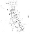
- FIG. 1 illustrates an embodiment of a selective folding apparatus generally designated as numeral 5.
- Selective folding apparatus 5 may include a first pathway 12 for cut web products 20, a second pathway 10 for redirected or folded cut web products 22, a conveyor system 14, and a redirecting or folding mechanism 18 for folding cut web products 20 and delivering folded cut web products 22 to second pathway 10.
- selective folding apparatus 5 may further include a defect sensor 24, for detecting cut web products 20 that contain at least one defect or otherwise do not meet satisfactory conditions.
- selective folding apparatus 5 may include a cutting-device 16 for cutting a continuous length of web material into cut web products 20 prior to delivering cut web products 20 to first pathway 12.
- the cutting device 16 is shown adjacent to first pathway 12.
- cutting device 16 need not be adjacent first pathway 12
- selective folding apparatus 5 may comprise one or more intermediary paths or subject cut web products 20 to further processes prior to entering first pathway 12.
- selective folding apparatus 5 need not include cutting device 16 nor be attached to any other intermediary paths or further processing devices and may comprise a standalone apparatus.
- cut web products 20 are delivered, manually or mechanically, to first pathway 12. Cut web products 20 travel along first pathway 12 by means of conveyor system 14.
- conveyor system 14 comprises a belt and roller system.
- conveyor system 14 may comprise any other suitable mechanism, including but not limited to, a conveyor or transport drum, for causing cut web products 20 to travel along first pathway 12.
- Cut web products 20 travel along first pathway 12 toward folding mechanism 18.
- folding mechanism 18 may selectively cause cut web products 20 to be folded and may further cause the folded cut web products 22 to be delivered to second pathway 10.
- folded cut web products 22 may travel along second pathway 10 by means of conveyor system 14 toward an exit of selective folding apparatus 5.
- folded cut web products 22 may travel along other paths or be subjected to further processing, such as testing, stacking, packaging, etc.
- folded cut web products 22 may travel along second pathway 10 toward a second folding mechanism, whereby folded cut web products 22 are folded, selectively folded, or redirected a second time.
- folding mechanism 18 may fold, or selectively fold, cut web products 20 across a first fold, wherein a first portion of cut web products 20 are folded over a second portion of cut web products 20.
- the partially folded cut web products may then be delivered to a second folding mechanism, whereby-the partially folded cut web products may be folded, or selectively folded, a second time, such that a third portion of cut web products 20 is folded over the first/second folded portions of cut web products 20, such as wherein a tri-folded cut web product is desired.
- cut web products 20 may pass by, and be selectively subjected to, any number of folding mechanisms, such as three, four, or more folding mechanisms.
- multiple folding mechanisms may be desired for any number of reasons, including but not limited to, directing cut web products 20 to alternate pathways, creating multiple folds in cut web products 20, rejecting cut web products 20 based on specific characteristics, etc.
- one or more second pathways 82, 84, 86 may be provided for which cut web products 20 may be redirected from first pathway 12.
- a single pathway may be provided, while in other embodiments two or more pathways may be provided.
- multiple second pathways 82, 84, 86 may provide separate pathways for folding cut web products 20 using alternative methods of folding, such as, but not limited to, bi-folding, tri-folding, quad-folding, wrapping, rolling, or hand folding, or any combination thereof, including providing one or more second pathways 82, 84, 86 for any method of folding.
- a selected number of cut web products 20 may be redirected to one or more second pathways 82, 84, 86 for reasons relating to, but not limited to, the speed of conveyor system 14, the relative line speed of first pathway 12 compared with the speed of an apparatus used for folding, stacking, packaging, etc.
- cut web products 20 traveling along first pathway 12 may be selected for redirection to one of the multiple second pathways 82, 84, 86, such that half of cut web products 20 are redirected to a particular second pathway, a third of cut web products 20 are redirected to a particular second pathway, a fourth of cut web products 20 are delivered to a particular second pathway, or any other suitable fraction of cut web products 20 traveling along first pathway 12 may be redirected to a particular second pathway.
- the product stream of cut web products 20 may be divided among more than one second pathway for further processing.
- Further processing in any of the multiple second pathways 82, 84, 86 may include, but is not limited to, folding, testing, stacking, packaging, etc. Furthermore, the processing in any particular second pathway 82, 84, 86 may differ from the processing in any of the other multiple second pathways 82, 84, 86.
- folding mechanism 18 may include dual propeller-style tuckers 28, which rotate in opposite directions, indicated by rotational arrows R1 and R2.
- folding mechanism 18 comprises dual propeller-slyle tuckers 28, each propeller-style tucker having two blades 30 each.
- a fewer or greater number of blades 30 may be provided on each propeller-style tucker 28.
- propeller-style tucker 28 may comprise a single blade 30 or may comprise three or more blades 30.
- a single propeller-style tucker 28 may be provided instead of dual propeller-style tuckers 28.
- any suitable number of propeller-style tuckers 28, each with any suitable number of blades 30, may be provided.
- the blades may be provided in any desired shape or configuration.
- propeller-style tuckers 28 may be phased such that blades 30 engage cut web products 20 as the cut web products 20 travel along first pathway 12 and pass by folding mechanism 18.
- Blades 30 may engage cut web products 20 for folding at any position.
- blades 30 may engage cut web products 20 at a substantially center position, thereby folding cut web products 20 substantially in half. Ilowever, it is recognized that blades 30 may engage cut web products 20 in a position other than substantially at the center of cut web products 20, as may be done when cut web products 20 will be folded more than a single time.
- Dual propeller style tuckers 28 may further direct folded cut web products 22 to second pathway 10.
- FIG. 4A illustrates a further embodiment of folding mechanism 18.
- Folding mechanism 18 may include tucker blade 32, shaft 34, fixed gear 36, rotating gear 38, and drive belt 40.
- Rotating gear 38 may orbit fixed gear 36, as shown by rotational arrow R3.
- fixed gear 36 and drive belt 40 may cause rotating gear 38 to rotate around its central axis.
- One end of tucker blade 32 may be fixed at substantially near the central axis of rotating gear 38, thereby causing tucker blade 32 to rotate with rotating gear 38.
- Other suitable means may be used for obtaining substantially the same effect and rotation of tucker blade 32, including, for example, replacing drive belt 40 with at least one gear or gearbox. It is further recognized that more than one rotating gear 38 and tucker blade 32 may be provided to orbit fixed gear 36.
- Figure 4B illustrates a path that may be followed by tucker blade 32 in an embodiment of folding mechanism 18 illustrated in Figure 4A .
- the dashed-line tucker blades represent positions that tucker blade 32 may be located at some time throughout the orbit and rotation of rotating gear 38.
- shaft 34, fixed gear 36, rotating gear 38, and drive belt 40 have been removed from Figure 4B .
- folding mechanism 18 may be phased such that tucker blade 32 engages cut web products 20 as the cut web products 20 travel along first pathway 12 and pass by folding mechanism 18.
- Tucker blade 32 may engage cut web products 20 for folding at any position.
- tucker blade 32 may engage cut web products 20 at a substantially center position, thereby folding cut web products 20 substantially in half.
- it is recognized that tucker blade 32 may engage folding cut web products 20 in a position other than substantially at the center of cut web products 20, as may be done when cut web products 20 will be folded more than a single time.
- Tucker blade 32 may further direct folded cut web products 22 to second pathway 10.
- Folding mechanism may include tucker arm 50 and rotating arm 52.
- Tucker arm 50 may be attached at one end to rotating arm 52.
- Rotating arm 52 may rotate in place around a central axis of rotating arm 52, such as is illustrated by rotational arrow R4.
- folding mechanism 18 may include more than one rotating arm 52, as shown in Figure 5A .
- rotating arm 52 may be a rotating bar, rotating plate, or rotating planetary gear system, or any other suitable structure or configuration. It is recognized that any means for rotating may be used for, or in place of, rotating arm 52.
- tucker arm 50 may follow the path shown by the dashed-line tucker arms in Figure 5A .
- the dashed-line tucker arms represent positions that tucker arm 50 may be located at some time throughout the orbit and rotation of rotating arm 52.
- tucker arm 50 may maintain a configuration wherein at any position during rotation, tucker arm 50 may be substantially parallel to any other position during rotation of tucker arm 50.
- folding mechanism 18 may be phased such that tucker arm 50 engages cut web products 20 as the cut web products 20 travel along first pathway 12 and pass by folding mechanism 18.
- Tucker arm 50 may engage cut web products 20 for folding at any position.
- tucker ann 50 may engage cut web products 20 at a substantially center position, thereby folding cut web products 20 substantially in half.
- tucker arm 50 may engage folding cut web products 20 in a position other than substantially at the center of cut web products 20, as may be done when cut web products 20 will be folded more than a single time.
- Tucker arm 50 may further direct folded cut web products 22 to second pathway 10.
- folding mechanism 18 also may be appropriate for use with some embodiments of selective folding apparatus 5 of the present disclosure.
- tucker, tucker blade, or tucker arm may refer to any suitable mechanism for engaging the cut web products 20 and causing the cut web products 20 to be redirected and/or folded about an axis - typically, though not exclusively, an imaginary line - that defines two or more generally symmetrical or asymmetrical portions of the cut web product 20.
- tucker blades 30 and 32 and tucker arm 50 may be manufactured from any suitable materials such as, but not limited to, metal, metallic alloys, plastics, etc., or combinations thereof.
- Folding mechanism 18 may comprise any drive mechanism 74 for operating a tucker blade.
- drive mechanism 74 may be a line shaft drive mechanism comprising main shaft 60, phasing gear box 62, disengagement clutch 64, and linking belt 68. Not all components of the line shaft drive mechanism shown in Figure 6 are required, and some components may be eliminated from the line shaft drive mechanism without departing from the scope of the present disclosure, while others may be added or substituted.
- main shaft 60 may directly drive the folding mechanism 18.
- main shaft 60 may indirectly drive the folding mechanism 18.
- the main shaft 60 may be linked to phasing gear box 62, which may phase the driving rotation of main shaft 60 to align the engagement of folding mechanism 18 with passing cut web products 20.
- a line shaft drive mechanism may further include disengagement clutch 64.
- Disengagement clutch 64 may cause folding mechanism 18 to slow down, stop, and/or restart during operation of selective folding apparatus 5. That is, at any suitable moment, disengagement clutch 64 may cause drive mechanism 74 to slow down or stop, which may further prevent folding mechanism 18 from engaging cut web product 20, folding cut web product 20, or delivering cut web product 20 to second pathway 10.
- disengagement clutch 64 may be replaced by other suitable mechanisms for slowing or stopping folding mechanism 18 from engaging cut web product 20, folding cut web product 20, or delivering cut web product 20 to second pathway 10.
- Linking belt 68 may link main shaft 60, phasing gear box 62, or disengagement clutch 64 with tucker blades 30 or 32 or tucker arm 50.
- linking belt 68 may be a belt or chain.
- linking belt 68 may be any suitable means for connecting main shaft 60, phasing gear box 62, or disengagement clutch 64 with tucker blades 30 or 32 or tucker arm 50, such that drive mechanism 74 is linked to tucker blades 30 or 32 or tucker arm 50, such as via gears or gearboxes.
- drive mechanism 74 may include motor 66 and linking belt 68.
- Motor 66 in a further embodiment, may be a servo motor for controlling the position of tucker blades 30 or 32 or tucker arm 50 of folding mechanism 18.
- a servo motor may be used to alter the speed of folding mechanism 18 quickly, including accelerating, decelerating, stopping, and restarting folding mechanism 18 in a very short period of time.
- a servo motor may be used to accelerate, decelerate, stop, and restart folding mechanism 18, including in a relatively short period of time, such as seconds or fractions of a second, such as milliseconds.
- Linking belt 68 may link motor 66 with tucker blades 30 or 32 or tucker arm 50.
- linking belt 68 may be a belt or chain.
- linking belt 68 may be any suitable means for linking motor 66 with tucker blades 30 or 32 or tucker arm 50, such that drive mechanism 74 is linked to tucker blades 30 or 32 or tucker arm 50, such as via gears or gearboxes.
- Drive mechanism 74 illustrated in Figure 7 , may provide less driven inertia and lower momentum forces during slowing or stopping of folding mechanism 18 and may allow faster conveyor speeds and higher precision of folding mechanism 18 than the mechanism illustrated in Figure 6 .
- linking belt 68 may be eliminated from drive mechanism 74.
- Motor 66 such as a servo motor, may be linked directly to tucker blades 30 or 32 or tucker arm 50, such that the motor 66 directly controls tucker blades 30 or 32 or tucker arm 50.
- Drive mechanism 74 illustrated in Figure 8 , may provide even less driven inertia and lower momentum forces during slowing or stopping of folding mechanism 18 and may allow even faster conveyor speeds and higher precision of folding mechanism 18 than the mechanisms in Figure 6 or 7 .
- folding mechanism 18 illustrated in Figures 6-8 includes dual propeller-style tuckers 28, it is recognized that any tucker blade, or any other suitable structure, may be used in accordance with folding mechanism 18 of the present disclosure.
- folding mechanism 18 may comprise any tucker blade system described above in combination with any drive mechanism 74 described above.
- folding mechanism 18 may comprise any suitable tucker blade system in combination with any suitable drive mechanism.
- cut web products 20 are delivered, manually or mechanically, to first pathway 12. Cut web products 20 travel along first pathway 12 by means of conveyor system 14 toward folding mechanism 18.
- folding mechanism 18 may selectively cause cut web products 20 to be folded and may further cause the folded cut web products 22 to be delivered to second pathway 10. That is, folding mechanism 18, in an embodiment, may cause some cut web products 20 to be folded and delivered to second pathway 10 while folding mechanism 18 allows other cut web products 20 to pass by without causing the cut web products 20 to be folded or delivered to second pathway 10.
- Folding mechanism 18, in an embodiment, may allow some cut web products 20 to pass without being folded and delivered to second pathway 10 by slowing down, such that folding mechanism 18 does not engage the cut web products 20 that have been selected to bypass folding mechanism 18.
- folding mechanism 18 may allow some cut web products 20 to pass without being folded and delivered to second pathway 10 by stopping, or pausing, the tucker blades or tucker arm in mid-operation, such that folding mechanism 18 is stopped in a position that avoids engagement with cut web products 20 that have been selected to bypass folding mechanism 18. After cut web product 20 bypasses folding mechanism 18, folding mechanism 18 may be accelerated to operating speed or to another suitable speed.
- folding mechanism 18 may be accelerated to operating speed by the time the next consecutive cut web product 20, which immediately follows the cut web product 20 that was selected to bypass folding mechanism 18, reaches folding mechanism 18. In such an embodiment, folding mechanism 18 need not be disengaged, physically and/or mechanically, from an engaging position to a non-engaging position, thereby reducing the need for space and/or moving parts.
- folding mechanism 18 may be decelerated, or substantially decelerated, such that the tucker blades or tucker arm may be allowed to pass through first pathway 12 between consecutive cut web products 20, such that the tucker blades or tucker arm do not contact cut web products 20 that have been selected to bypass folding mechanism 18. Subsequent a deceleration, folding mechanism 18 may increase its speed to substantially the same speed as during prior operation, or another suitable speed, such that the tucker blades or tucker arm may continue to pass through first pathway 12 between consecutive cut web products 20, thereby allowing consecutive cut web products 20 to bypass folding mechanism 18.
- folding mechanism 18 may be decelerated or substantially decelerated, and then accelerated or substantially accelerated, such that the tucker blades or tucker arm are in a position that does not redirect cut web products 20 to second pathway 10. That is, folding mechanism 18 may be decelerated or substantially decelerated, and then accelerated or substantially accelerated, such that the tucker blades or tucker arm are out of phase with cut web products 20 traveling along first pathway 12.
- folding mechanism 18 may be decelerated or substantially decelerated, and then accelerated or substantially accelerated, such that a single cut web product 20 is allowed to bypass folding mechanism 18, and then folding mechanism 18 may be phased, by acceleration or deceleration, back in accordance with cut web products 20 traveling along first pathway 12, such that cut web products 20 arc once again folded and delivered to second pathway 10.
- more than a single consecutive cut web product 20 may be allowed to bypass folding mechanism 18 before folding mechanism 18 is phased back in accordance with cut web products 20.
- selective folding apparatus 5 may further include a defect sensor 24 for detecting cut web products 20 that contain at least one defect or otherwise do not meet satisfactory conditions.
- defect sensor 24 may be located prior to folding mechanism 18, such that defective cut web products are detected prior to reaching folding mechanism 18. In such an embodiment, defect sensor 24 may be located at any position prior to folding mechanism 18. Defect sensor 24 need not be located near folding mechanism 18. Additionally, defect sensor 24 need not be located near cutting device 16, as illustrated in the figures.
- folding apparatus 5 may include more than one defect sensor 24. Defect sensor 24 may be configured to evaluate each cut web product, or any desired subset, sampling, etc. thereof.
- the defect sensor 24 detects every third cut web product 20, that sensed product may be treated as representative of those that precede and follow it.
- cut web products 20 that contain at least one defect or otherwise do not meet satisfactory conditions may be selected to bypass folding mechanism 18, such that the defective cut web products 72 (shown in Figure 9 ) are not folded or delivered to second pathway 10.
- defective cut web products 72 may be delivered to an alternate pathway or may be subjected to alternate processes, such as testing, destruction, other commercial or other uses, etc.
- a further embodiment of selective folding apparatus 5, shown in Figure 9 includes a location where cut web products 72, which have been determined to contain a defect or are unsatisfactory for any reason, are delivered.
- cut web products 72 that have been determined to contain a defect or are unsatisfactory for any reason are delivered to reject bin 70.
- reject bin 70 may comprise a removable bin where defective cut web products 72 are delivered or disposed.
- reject bin 70 may be an incinerator, a trash compactor, or any other suitable device for disposal of defective cut web products 72.
- cut web products 72 that have been determined to contain a defect or are unsatisfactory for any reason may be delivered to further paths or subjected to further processes, including but not limited to, testing, destruction, etc.
- cut web products 20 are delivered, manually or mechanically, to first pathway 12. Cut web products 20, travel along first pathway 12 by means of conveyor system 14.
- conveyor system 14 comprises a belt and roller system.
- conveyor system 14 may comprise any other suitable conveyor means of causing cut web products 20 to travel along first pathway 12. Cut web products travel along first pathway 12 toward folding mechanism 18.
- folding mechanism 18 may selectively cause cut web products 20 to be folded and may further cause the folded cut web products 22 to be delivered to second pathway 10 or multiple second pathways as described with reference to Figure 2 .
- folded cut web products 22 may travel along second pathway 10 by means of conveyor system 14 toward an exit of selective folding apparatus 5, as was described with reference to Figure 1 .
- folding mechanism 18 may be caused to be slowed, including substantially slowed, in order to allow defective cut web product 72 to bypass folding mechanism 18.
- folding mechanism 18 may be caused to be nearly stopped, substantially stopped, or stopped completely, to allow defective cut web product 72 to bypass folding mechanism 18.
- Folding mechanism 18 may allow defective cut web product 72 to pass without folding defective cut web product 72.
- folding mechanism 18 may allow defective cut web product 72 to pass without delivering defective cut web product 72 to second pathway 10.
- folding mechanism 18 may be slowed, substantially slowed, or stopped, such that the tucker blade or tucker arm does not come into contact with defective cut web product 72. That is, folding mechanism 18 may be slowed, substantially slowed, or stopped, such that the tucker blade or tucker arm is in a position that docs not block defective cut web product 72 from bypassing folding mechanism 18.
- folding mechanism 18 may be decelerated, or substantially decelerated, such that the tucker blades or tucker arm may be allowed to pass through first pathway 12 between consecutive cut web products 20, such that the tucker blades or tucker arm do not contact defective cut web products 72. Subsequent to deceleration, folding mechanism 18 may increase its speed to substantially the same speed as during prior operation, or another suitable speed, such that the tucker blades or tucker arm may continue to pass through first pathway 12 between consecutive defective cut web products 72, thereby allowing consecutive defective cut web products 72 to bypass folding mechanism 18.
- folding mechanism 18 may be decelerated or substantially decelerated, and then accelerated or substantially accelerated, such that the tucker blades or tucker arm are in a position that does not redirect defective cut web products 72 to second pathway 10. That is, folding mechanism 18 may be decelerated or substantially decelerated, and then accelerated or substantially accelerated, such that the tucker blades or tucker arm are out of phase with cut web products 20 traveling along first pathway 12.
- folding mechanism 18 may be decelerated or substantially decelerated, and then accelerated or substantially accelerated, such that a single defective cut web product 72 is allowed to bypass folding mechanism 18, and then folding mechanism 18 may be phased, by acceleration or deceleration, back in accordance with cut web products 20 traveling on first pathway 12, such that cut web products 20 are once again folded and delivered to second pathway 10.
- more than a single consecutive defective cut web product 72 may he allowed to bypass folding mechanism 18 before folding mechanism 18 is phased back in accordance with cut web products 20.
- defective cut web product 72 may bypass folding mechanism 18 and travel toward reject bin 70. In other embodiments, defective cut web product 72 may bypass folding mechanism 18 and travel toward further paths or subjected to further processes, including but not limited to testing, destruction, etc. After defective cut web product 72 bypasses folding mechanism 18, folding mechanism 18 may be accelerated to operating speed or another speed. In an embodiment, folding mechanism 18 may be accelerated to operating speed by the time the next consecutive cut web product 20 immediately following defective cut web product 72 reaches folding mechanism 18.
Landscapes
- Engineering & Computer Science (AREA)
- Health & Medical Sciences (AREA)
- Mechanical Engineering (AREA)
- Heart & Thoracic Surgery (AREA)
- Epidemiology (AREA)
- Biomedical Technology (AREA)
- Manufacturing & Machinery (AREA)
- Vascular Medicine (AREA)
- Life Sciences & Earth Sciences (AREA)
- Animal Behavior & Ethology (AREA)
- General Health & Medical Sciences (AREA)
- Public Health (AREA)
- Veterinary Medicine (AREA)
- Folding Of Thin Sheet-Like Materials, Special Discharging Devices, And Others (AREA)
- Absorbent Articles And Supports Therefor (AREA)
Description
- The present disclosure relates to a method for selective folding or redirecting of cut web products. More particularly, the present disclosure relates to a method for high speed selective folding, redirecting, and/or rejecting of cut web products, such as diapers or catamenials.
- In some instances, there may be a desire to redirect cut web products on a high speed production line to a different production stream. In other cases, some cut products manufactured on a high speed production line may contain defects. Several mechanisms exist for rejecting defective cut web products, such as by diverting the defective cut web products from the stream of cut web products that are of satisfactory condition or good quality. One method that has been used to reject cut web products includes forcing the defective cut web products out of the stream of satisfactory products by using pneumatic air blasts, which divert the defective cut web products to a path that differs from that for the stream of satisfactory products. In such a method, the defective cut web products are detected, and a pneumatic air blast forces the defective cut web products out of the stream of quality products and into a reject gap provided in the conveyor system or production line. Typically, the reject gap will be provided prior to subjecting the cut web products to further processing, such as folding. Methods of rejecting cut web products using pneumatic air blasts involve several disadvantages. Devices creating pneumatic air blasts require space. Similarly, extra space along the conveyor system is required to include a reject gap. A reject gap further involves system reliability issues related to having a gap in the conveyor system, such as jamming. Additionally, pneumatic air blasts create excessive dust and noise. Furthermore, pneumatic air blasts are not entirely accurate and can divert more than solely the defective cut web product from the stream of satisfactory products. Also, the equipment to create, convey, regulate, and control the air blast is expensive to install and operate.
- A similar method of rejecting cut web products includes using a vacuum to remove the defective cut web products from the stream of quality products. The use of a vacuum, rather than pneumatic air blasts, involves similar disadvantages, such as requiring large amounts of space for the vacuum device, providing extra space along the conveyor system for the reject gap, creating excessive noise and dust, etc. Also, the additional vacuum equipment and vacuum creation, control, and transportation is expensive.
- Another method of rejecting cut web products includes mechanically activated switches, or flippers, that divert the defective cut web products to an alternative pathway, similar to the manner railway switches can divert trains to a different track. The mechanical switches are commonly activated via a pneumatic or hydraulic cylinder or via an electric motor. A typical configuration includes mechanical switches that pop up from the conveyor system and divert the defective cut web products below the switch towards an alternate pathway. Rejection of defective cut web products typically takes place before the cut web products are subjected to further processing, such as folding. As such, more space is required to create room for the mechanically activated switches and the alternate pathway. Thus, space consumption is a disadvantage to the mechanical switch method. Furthermore, the additional mechanical switch equipment is expensive.
-
US 4,650,173, issued on March 17th 1987 , relates to a method and apparatus for operating a diaper-producing machine where a series of unfolded diapers are advanced along a path containing a plurality of stackers each having a folding blade, the apparatus having means for periodically altering the movement of one blade to permit diaper movement past that stacker to a subsequent one, thereby continuing stacking while a previously completed stack is removed. - A method and apparatus for high speed selective folding, redirecting, and/or rejecting of cut web products that is compact may be desirable. Further, a method and apparatus that is accurate in removing only the selected cut web products from the stream of quality products may also be desirable. Further, a method and apparatus that creates less noise and dust may be desirable. A method and system that does not need a reject gap in the conveyor system also may be desirable. Additionally, a system that uses existing equipment and control mechanisms to reject products rather than adding equipment and ancillary devices to perform this task may be desirable.
- The present disclosure, in an embodiment, is a method for rejecting defective cut web products. A plurality of cut web products may advance along a first path. A folding device may be provided for folding the cut web products and delivering the folded cut web products to a second path. Some of the cut web products may be determined to be defective. As such, the folding device may be slowed down, substantially slowed down, or substantially stopped, such that the defective cut web product is not delivered to the second path.
- While multiple embodiments are disclosed, still other embodiments of the present disclosure will become apparent to those skilled in the art from the following detailed description, which shows and describes illustrative embodiments of the invention.
- Accordingly, the drawings and detailed description are to be regarded as illustrative in nature and not restrictive.
- While the specification concludes with claims particularly pointing out and distinctly claiming the subject matter that is regarded as forming the present disclosure, it is believed that the invention will be better understood from the following description taken in conjunction with the accompanying figures, in which:
-
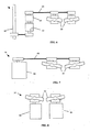
Figure 1 is a side view of a selective folding apparatus in accordance with an embodiment of the present disclosure. -
Figure 2 is a side view of a selective folding apparatus in accordance with another embodiment of the present disclosure. -
Figure 3A is a front view of a folding mechanism of a selective folding apparatus in accordance with another embodiment of the present disclosure. -
Figure 3B is a side view of a folding mechanism of a selective folding apparatus in accordance with an embodiment of a folding mechanism ofFigure 3A . -
Figure 4A is a side view of a folding mechanism of a selective folding apparatus in accordance with yet another embodiment of the present disclosure. -
Figure 4B is a side view of the path followed by a folding mechanism of a selective folding apparatus in accordance with an embodiment of a folding mechanism ofFigure 4A . -
Figure 5A is a front view of a folding mechanism of a selective folding apparatus in accordance with a further embodiment of the present disclosure. -
Figure 5B is a side view of a folding mechanism of a selective folding apparatus in accordance with an embodiment of a folding mechanism ofFigure 5A . -
Figure 6 is a front view of a drive mechanism of a folding mechanism of a selective folding apparatus in accordance with another embodiment of the present disclosure. -
Figure 7 is a front view of a drive mechanism of a folding mechanism of a selective folding apparatus in accordance with yet another embodiment of the present disclosure. -
Figure 8 is a front view of a drive mechanism of a folding mechanism of a selective folding apparatus in accordance with a further embodiment of the present disclosure. -
Figure 9 is a side view of a selective folding apparatus in accordance with another embodiment of the present disclosure. - The present disclosure relates to a novel and advantageous method and apparatus for selectively folding, redirecting, and/or rejecting a cut web product. The method and apparatus of the present disclosure may be used with any suitable cut web product. Examples of cut web products that may be used with the present disclosure include, but are not limited to, diapers, napkins, wet wipes, feminine care products, paper products, packaged products, etc. In some embodiments of the selective folding apparatus of the present disclosure, it may be desirable to redirect or reject a particular cut web product, for example when a particular cut web product is determined to contain a defect. A cut web product alternatively may be redirected or rejected for any number of reasons, including for any variety of reasons that the cut web product is unsatisfactory in any characteristic. In one embodiment, where it is desirable to redirect or reject a particular cut web product, it may further be desirable to allow the cut web product to pass or bypass a folding portion of the selective folding apparatus.
-
Figure 1 illustrates an embodiment of a selective folding apparatus generally designated asnumeral 5.Selective folding apparatus 5 may include afirst pathway 12 for cutweb products 20, asecond pathway 10 for redirected or foldedcut web products 22, aconveyor system 14, and a redirecting orfolding mechanism 18 for foldingcut web products 20 and delivering foldedcut web products 22 tosecond pathway 10. In some embodiments,selective folding apparatus 5 may further include adefect sensor 24, for detectingcut web products 20 that contain at least one defect or otherwise do not meet satisfactory conditions. - In a further embodiment,
selective folding apparatus 5 may include a cutting-device 16 for cutting a continuous length of web material intocut web products 20 prior to deliveringcut web products 20 tofirst pathway 12. In an embodiment shown inFigure 1 , the cuttingdevice 16 is shown adjacent tofirst pathway 12. In other embodiments, cuttingdevice 16 need not be adjacentfirst pathway 12, andselective folding apparatus 5 may comprise one or more intermediary paths or subjectcut web products 20 to further processes prior to enteringfirst pathway 12. In yet other embodiments,selective folding apparatus 5 need not include cuttingdevice 16 nor be attached to any other intermediary paths or further processing devices and may comprise a standalone apparatus. - As illustrated in
Figure 1 , in an embodiment, cutweb products 20 are delivered, manually or mechanically, tofirst pathway 12. Cutweb products 20 travel alongfirst pathway 12 by means ofconveyor system 14. In an embodiment,conveyor system 14 comprises a belt and roller system. In other embodiments,conveyor system 14 may comprise any other suitable mechanism, including but not limited to, a conveyor or transport drum, for causingcut web products 20 to travel alongfirst pathway 12. - Cut
web products 20 travel alongfirst pathway 12 towardfolding mechanism 18. In an embodiment,folding mechanism 18 may selectively cause cutweb products 20 to be folded and may further cause the foldedcut web products 22 to be delivered tosecond pathway 10. In some embodiments, foldedcut web products 22 may travel alongsecond pathway 10 by means ofconveyor system 14 toward an exit ofselective folding apparatus 5. In further embodiments, foldedcut web products 22 may travel along other paths or be subjected to further processing, such as testing, stacking, packaging, etc. For example, in an embodiment, foldedcut web products 22 may travel alongsecond pathway 10 toward a second folding mechanism, whereby foldedcut web products 22 are folded, selectively folded, or redirected a second time. In a further example,folding mechanism 18 may fold, or selectively fold, cutweb products 20 across a first fold, wherein a first portion ofcut web products 20 are folded over a second portion ofcut web products 20. The partially folded cut web products may then be delivered to a second folding mechanism, whereby-the partially folded cut web products may be folded, or selectively folded, a second time, such that a third portion ofcut web products 20 is folded over the first/second folded portions ofcut web products 20, such as wherein a tri-folded cut web product is desired. In alternative embodiments, cutweb products 20 may pass by, and be selectively subjected to, any number of folding mechanisms, such as three, four, or more folding mechanisms. In some embodiments, multiple folding mechanisms may be desired for any number of reasons, including but not limited to, directingcut web products 20 to alternate pathways, creating multiple folds incut web products 20, rejectingcut web products 20 based on specific characteristics, etc. - In an embodiment of
selective folding apparatus 5, shown inFigure 2 , one or moresecond pathways web products 20 may be redirected fromfirst pathway 12. In an embodiment, a single pathway may be provided, while in other embodiments two or more pathways may be provided. - For example, in an embodiment, multiple
second pathways cut web products 20 using alternative methods of folding, such as, but not limited to, bi-folding, tri-folding, quad-folding, wrapping, rolling, or hand folding, or any combination thereof, including providing one or moresecond pathways cut web products 20 may be redirected to one or moresecond pathways conveyor system 14, the relative line speed offirst pathway 12 compared with the speed of an apparatus used for folding, stacking, packaging, etc. onsecond pathways selective folding apparatus 5 relating to the effects of production line speeds on the resulting end product. In yet another embodiment, cutweb products 20 traveling alongfirst pathway 12 may be selected for redirection to one of the multiplesecond pathways cut web products 20 are redirected to a particular second pathway, a third ofcut web products 20 are redirected to a particular second pathway, a fourth ofcut web products 20 are delivered to a particular second pathway, or any other suitable fraction ofcut web products 20 traveling alongfirst pathway 12 may be redirected to a particular second pathway. As such, the product stream ofcut web products 20 may be divided among more than one second pathway for further processing. Further processing in any of the multiplesecond pathways second pathway second pathways - In an embodiment of
selective folding apparatus 5, shown inFigure 3A ,folding mechanism 18 may include dual propeller-style tuckers 28, which rotate in opposite directions, indicated by rotational arrows R1 and R2. In a further embodiment,folding mechanism 18 comprises dual propeller-slyle tuckers 28, each propeller-style tucker having twoblades 30 each. In other embodiment, a fewer or greater number ofblades 30 may be provided on each propeller-style tucker 28. For example, propeller-style tucker 28 may comprise asingle blade 30 or may comprise three ormore blades 30. In yet other embodiments, it is recognized that a single propeller-style tucker 28 may be provided instead of dual propeller-style tuckers 28. It is recognized further that any suitable number of propeller-style tuckers 28, each with any suitable number ofblades 30, may be provided. The blades may be provided in any desired shape or configuration. - As can be seen in
Figure 3B , propeller-style tuckers 28 may be phased such thatblades 30 engagecut web products 20 as thecut web products 20 travel alongfirst pathway 12 and pass by foldingmechanism 18.Blades 30 may engage cutweb products 20 for folding at any position. For example, in an embodiment,blades 30 may engage cutweb products 20 at a substantially center position, thereby foldingcut web products 20 substantially in half. Ilowever, it is recognized thatblades 30 may engage cutweb products 20 in a position other than substantially at the center ofcut web products 20, as may be done when cutweb products 20 will be folded more than a single time. Dual propeller style tuckers 28 may further direct foldedcut web products 22 tosecond pathway 10. -
Figure 4A illustrates a further embodiment offolding mechanism 18.Folding mechanism 18 may includetucker blade 32,shaft 34, fixedgear 36, rotatinggear 38, and drivebelt 40. Rotatinggear 38 may orbit fixedgear 36, as shown by rotational arrow R3. In a further embodiment, fixedgear 36 anddrive belt 40 may causerotating gear 38 to rotate around its central axis. One end oftucker blade 32 may be fixed at substantially near the central axis ofrotating gear 38, thereby causingtucker blade 32 to rotate withrotating gear 38. Other suitable means may be used for obtaining substantially the same effect and rotation oftucker blade 32, including, for example, replacingdrive belt 40 with at least one gear or gearbox. It is further recognized that more than one rotatinggear 38 andtucker blade 32 may be provided to orbit fixedgear 36. -
Figure 4B illustrates a path that may be followed bytucker blade 32 in an embodiment offolding mechanism 18 illustrated inFigure 4A . The dashed-line tucker blades represent positions thattucker blade 32 may be located at some time throughout the orbit and rotation ofrotating gear 38. For ease of illustration, embodiments ofshaft 34, fixedgear 36, rotatinggear 38, and drivebelt 40 have been removed fromFigure 4B . - As can be seen in
Figure 4B ,folding mechanism 18 may be phased such thattucker blade 32 engages cutweb products 20 as thecut web products 20 travel alongfirst pathway 12 and pass by foldingmechanism 18.Tucker blade 32 may engage cutweb products 20 for folding at any position. For example, in an embodiment,tucker blade 32 may engage cutweb products 20 at a substantially center position, thereby foldingcut web products 20 substantially in half. However, as previously stated, it is recognized thattucker blade 32 may engage foldingcut web products 20 in a position other than substantially at the center ofcut web products 20, as may be done when cutweb products 20 will be folded more than a single time.Tucker blade 32 may further direct foldedcut web products 22 tosecond pathway 10. - Yet another embodiment of
folding mechanism 18 can be seen inFigure 5A . Folding mechanism may includetucker arm 50 androtating arm 52.Tucker arm 50 may be attached at one end to rotatingarm 52. Rotatingarm 52 may rotate in place around a central axis ofrotating arm 52, such as is illustrated by rotational arrow R4. In some embodiments,folding mechanism 18 may include more than one rotatingarm 52, as shown inFigure 5A . In further embodiments, rotatingarm 52 may be a rotating bar, rotating plate, or rotating planetary gear system, or any other suitable structure or configuration. It is recognized that any means for rotating may be used for, or in place of, rotatingarm 52. As rotatingarm 52 rotates,tucker arm 50 may follow the path shown by the dashed-line tucker arms inFigure 5A . The dashed-line tucker arms represent positions thattucker arm 50 may be located at some time throughout the orbit and rotation of rotatingarm 52. As can be seen inFigure 5A , astucker arm 50 rotates withrotating arm 52, it may maintain a configuration wherein at any position during rotation,tucker arm 50 may be substantially parallel to any other position during rotation oftucker arm 50. - As can be seen in
Figure 5B ,folding mechanism 18 may be phased such thattucker arm 50 engages cutweb products 20 as thecut web products 20 travel alongfirst pathway 12 and pass by foldingmechanism 18.Tucker arm 50 may engage cutweb products 20 for folding at any position. For example, in an embodiment,tucker ann 50 may engage cutweb products 20 at a substantially center position, thereby foldingcut web products 20 substantially in half. However, as previously stated, it is recognized thattucker arm 50 may engage foldingcut web products 20 in a position other than substantially at the center ofcut web products 20, as may be done when cutweb products 20 will be folded more than a single time.Tucker arm 50 may further direct foldedcut web products 22 tosecond pathway 10. - Other suitable forms of
folding mechanism 18 also may be appropriate for use with some embodiments ofselective folding apparatus 5 of the present disclosure. It is further recognized that the terms tucker, tucker blade, or tucker arm may refer to any suitable mechanism for engaging thecut web products 20 and causing thecut web products 20 to be redirected and/or folded about an axis - typically, though not exclusively, an imaginary line - that defines two or more generally symmetrical or asymmetrical portions of thecut web product 20. Furthermore,tucker blades tucker arm 50 may be manufactured from any suitable materials such as, but not limited to, metal, metallic alloys, plastics, etc., or combinations thereof. -
Folding mechanism 18 may comprise anydrive mechanism 74 for operating a tucker blade. In an embodiment offolding mechanism 18, illustrated inFigure 6 ,drive mechanism 74 may be a line shaft drive mechanism comprisingmain shaft 60,phasing gear box 62,disengagement clutch 64, and linkingbelt 68. Not all components of the line shaft drive mechanism shown inFigure 6 are required, and some components may be eliminated from the line shaft drive mechanism without departing from the scope of the present disclosure, while others may be added or substituted. - In an embodiment,
main shaft 60 may directly drive thefolding mechanism 18. In a further embodiment,main shaft 60 may indirectly drive thefolding mechanism 18. For example, in an embodiment, themain shaft 60 may be linked tophasing gear box 62, which may phase the driving rotation ofmain shaft 60 to align the engagement offolding mechanism 18 with passingcut web products 20. A line shaft drive mechanism may further includedisengagement clutch 64.Disengagement clutch 64 may causefolding mechanism 18 to slow down, stop, and/or restart during operation ofselective folding apparatus 5. That is, at any suitable moment, disengagement clutch 64 may causedrive mechanism 74 to slow down or stop, which may further preventfolding mechanism 18 from engagingcut web product 20, folding cutweb product 20, or deliveringcut web product 20 tosecond pathway 10. In other embodiments, disengagement clutch 64 may be replaced by other suitable mechanisms for slowing or stoppingfolding mechanism 18 from engagingcut web product 20, folding cutweb product 20, or deliveringcut web product 20 tosecond pathway 10. Linkingbelt 68 may linkmain shaft 60,phasing gear box 62, or disengagement clutch 64 withtucker blades tucker arm 50. In an embodiment, linkingbelt 68 may be a belt or chain. In alternative embodiments, linkingbelt 68 may be any suitable means for connectingmain shaft 60,phasing gear box 62, or disengagement clutch 64 withtucker blades tucker arm 50, such thatdrive mechanism 74 is linked totucker blades tucker arm 50, such as via gears or gearboxes. - In another embodiment, illustrated in
Figure 7 ,drive mechanism 74 may includemotor 66 and linkingbelt 68.Motor 66, in a further embodiment, may be a servo motor for controlling the position oftucker blades tucker arm 50 offolding mechanism 18. A servo motor may be used to alter the speed offolding mechanism 18 quickly, including accelerating, decelerating, stopping, and restartingfolding mechanism 18 in a very short period of time. For example, a servo motor may be used to accelerate, decelerate, stop, and restartfolding mechanism 18, including in a relatively short period of time, such as seconds or fractions of a second, such as milliseconds. In other embodiments a servo motor may be used to accelerate, decelerate, stop, and restartfolding mechanism 18 in any interval of time. Linkingbelt 68 may linkmotor 66 withtucker blades tucker arm 50. As previously stated, linkingbelt 68 may be a belt or chain. In alternative embodiments, linkingbelt 68 may be any suitable means for linkingmotor 66 withtucker blades tucker arm 50, such thatdrive mechanism 74 is linked totucker blades tucker arm 50, such as via gears or gearboxes.Drive mechanism 74, illustrated inFigure 7 , may provide less driven inertia and lower momentum forces during slowing or stopping offolding mechanism 18 and may allow faster conveyor speeds and higher precision offolding mechanism 18 than the mechanism illustrated inFigure 6 . - In yet a further embodiment, shown in
Figure 8 , linkingbelt 68 may be eliminated fromdrive mechanism 74.Motor 66, such as a servo motor, may be linked directly totucker blades tucker arm 50, such that themotor 66 directly controlstucker blades tucker arm 50.Drive mechanism 74, illustrated inFigure 8 , may provide even less driven inertia and lower momentum forces during slowing or stopping offolding mechanism 18 and may allow even faster conveyor speeds and higher precision offolding mechanism 18 than the mechanisms inFigure 6 or 7 . - Although folding
mechanism 18 illustrated inFigures 6-8 includes dual propeller-style tuckers 28, it is recognized that any tucker blade, or any other suitable structure, may be used in accordance withfolding mechanism 18 of the present disclosure. For example,folding mechanism 18 may comprise any tucker blade system described above in combination with anydrive mechanism 74 described above. Alternatively,folding mechanism 18 may comprise any suitable tucker blade system in combination with any suitable drive mechanism. - In an embodiment of
selective folding apparatus 5, cutweb products 20 are delivered, manually or mechanically, tofirst pathway 12. Cutweb products 20 travel alongfirst pathway 12 by means ofconveyor system 14 towardfolding mechanism 18. In an embodiment,folding mechanism 18 may selectively cause cutweb products 20 to be folded and may further cause the foldedcut web products 22 to be delivered tosecond pathway 10. That is,folding mechanism 18, in an embodiment, may cause somecut web products 20 to be folded and delivered tosecond pathway 10 while foldingmechanism 18 allows othercut web products 20 to pass by without causing thecut web products 20 to be folded or delivered tosecond pathway 10. -
Folding mechanism 18, in an embodiment, may allow somecut web products 20 to pass without being folded and delivered tosecond pathway 10 by slowing down, such thatfolding mechanism 18 does not engage thecut web products 20 that have been selected to bypassfolding mechanism 18. In a further embodiment,folding mechanism 18 may allow somecut web products 20 to pass without being folded and delivered tosecond pathway 10 by stopping, or pausing, the tucker blades or tucker arm in mid-operation, such thatfolding mechanism 18 is stopped in a position that avoids engagement withcut web products 20 that have been selected to bypassfolding mechanism 18. Aftercut web product 20bypasses folding mechanism 18,folding mechanism 18 may be accelerated to operating speed or to another suitable speed. In an embodiment,folding mechanism 18 may be accelerated to operating speed by the time the next consecutivecut web product 20, which immediately follows thecut web product 20 that was selected to bypassfolding mechanism 18, reachesfolding mechanism 18. In such an embodiment,folding mechanism 18 need not be disengaged, physically and/or mechanically, from an engaging position to a non-engaging position, thereby reducing the need for space and/or moving parts. - In a further embodiment,
folding mechanism 18 may be decelerated, or substantially decelerated, such that the tucker blades or tucker arm may be allowed to pass throughfirst pathway 12 between consecutivecut web products 20, such that the tucker blades or tucker arm do not contact cutweb products 20 that have been selected to bypassfolding mechanism 18. Subsequent a deceleration,folding mechanism 18 may increase its speed to substantially the same speed as during prior operation, or another suitable speed, such that the tucker blades or tucker arm may continue to pass throughfirst pathway 12 between consecutivecut web products 20, thereby allowing consecutivecut web products 20 to bypassfolding mechanism 18. That is,folding mechanism 18 may be decelerated or substantially decelerated, and then accelerated or substantially accelerated, such that the tucker blades or tucker arm are in a position that does not redirect cutweb products 20 tosecond pathway 10. That is,folding mechanism 18 may be decelerated or substantially decelerated, and then accelerated or substantially accelerated, such that the tucker blades or tucker arm are out of phase withcut web products 20 traveling alongfirst pathway 12. In an embodiment,folding mechanism 18 may be decelerated or substantially decelerated, and then accelerated or substantially accelerated, such that a singlecut web product 20 is allowed to bypassfolding mechanism 18, and then foldingmechanism 18 may be phased, by acceleration or deceleration, back in accordance withcut web products 20 traveling alongfirst pathway 12, such that cutweb products 20 arc once again folded and delivered tosecond pathway 10. In other embodiments, more than a single consecutivecut web product 20 may be allowed to bypassfolding mechanism 18 before foldingmechanism 18 is phased back in accordance withcut web products 20. - In some embodiments,
selective folding apparatus 5 may further include adefect sensor 24 for detectingcut web products 20 that contain at least one defect or otherwise do not meet satisfactory conditions. In an embodiment,defect sensor 24 may be located prior tofolding mechanism 18, such that defective cut web products are detected prior to reachingfolding mechanism 18. In such an embodiment,defect sensor 24 may be located at any position prior tofolding mechanism 18.Defect sensor 24 need not be located nearfolding mechanism 18. Additionally,defect sensor 24 need not be located near cuttingdevice 16, as illustrated in the figures. In some embodiments,folding apparatus 5 may include more than onedefect sensor 24.Defect sensor 24 may be configured to evaluate each cut web product, or any desired subset, sampling, etc. thereof. For example, in an embodiment, it may be desirable to sample a certain fraction of cut web products, and then, if appropriate, to group the sampled product with those adjacent to it. By way of example only, if thedefect sensor 24 detects every thirdcut web product 20, that sensed product may be treated as representative of those that precede and follow it. - In a further embodiment, cut
web products 20 that contain at least one defect or otherwise do not meet satisfactory conditions may be selected to bypassfolding mechanism 18, such that the defective cut web products 72 (shown inFigure 9 ) are not folded or delivered tosecond pathway 10. In some embodiments, defectivecut web products 72 may be delivered to an alternate pathway or may be subjected to alternate processes, such as testing, destruction, other commercial or other uses, etc. - A further embodiment of
selective folding apparatus 5, shown inFigure 9 , includes a location where cutweb products 72, which have been determined to contain a defect or are unsatisfactory for any reason, are delivered. InFigure 9 , cutweb products 72 that have been determined to contain a defect or are unsatisfactory for any reason are delivered to rejectbin 70. In some embodiments, rejectbin 70 may comprise a removable bin where defectivecut web products 72 are delivered or disposed. In other embodiments rejectbin 70 may be an incinerator, a trash compactor, or any other suitable device for disposal of defectivecut web products 72. In yet further embodiments, cutweb products 72 that have been determined to contain a defect or are unsatisfactory for any reason may be delivered to further paths or subjected to further processes, including but not limited to, testing, destruction, etc. - As illustrated in
Figure 9 , in an embodiment, cutweb products 20 are delivered, manually or mechanically, tofirst pathway 12. Cutweb products 20, travel alongfirst pathway 12 by means ofconveyor system 14. As previously stated, in an embodiment,conveyor system 14 comprises a belt and roller system. In other embodiments,conveyor system 14 may comprise any other suitable conveyor means of causing cutweb products 20 to travel alongfirst pathway 12. Cut web products travel alongfirst pathway 12 towardfolding mechanism 18. - In an embodiment,
folding mechanism 18 may selectively cause cutweb products 20 to be folded and may further cause the foldedcut web products 22 to be delivered tosecond pathway 10 or multiple second pathways as described with reference toFigure 2 . In some embodiments, foldedcut web products 22 may travel alongsecond pathway 10 by means ofconveyor system 14 toward an exit ofselective folding apparatus 5, as was described with reference toFigure 1 . - In some embodiments, however, where a
cut web product 20 has been determined to contain a defect or is unsatisfactory for any reason,folding mechanism 18 may be caused to be slowed, including substantially slowed, in order to allow defectivecut web product 72 to bypassfolding mechanism 18. In a further embodiment, ofselective folding apparatus 5,folding mechanism 18 may be caused to be nearly stopped, substantially stopped, or stopped completely, to allow defectivecut web product 72 to bypassfolding mechanism 18.Folding mechanism 18 may allow defectivecut web product 72 to pass without folding defectivecut web product 72. Similarly,folding mechanism 18 may allow defectivecut web product 72 to pass without delivering defectivecut web product 72 tosecond pathway 10. In an embodiment,folding mechanism 18 may be slowed, substantially slowed, or stopped, such that the tucker blade or tucker arm does not come into contact with defectivecut web product 72. That is,folding mechanism 18 may be slowed, substantially slowed, or stopped, such that the tucker blade or tucker arm is in a position that docs not block defectivecut web product 72 from bypassingfolding mechanism 18. - In a further embodiment,
folding mechanism 18 may be decelerated, or substantially decelerated, such that the tucker blades or tucker arm may be allowed to pass throughfirst pathway 12 between consecutivecut web products 20, such that the tucker blades or tucker arm do not contact defectivecut web products 72. Subsequent to deceleration,folding mechanism 18 may increase its speed to substantially the same speed as during prior operation, or another suitable speed, such that the tucker blades or tucker arm may continue to pass throughfirst pathway 12 between consecutive defectivecut web products 72, thereby allowing consecutive defectivecut web products 72 to bypassfolding mechanism 18. That is,folding mechanism 18 may be decelerated or substantially decelerated, and then accelerated or substantially accelerated, such that the tucker blades or tucker arm are in a position that does not redirect defectivecut web products 72 tosecond pathway 10. That is,folding mechanism 18 may be decelerated or substantially decelerated, and then accelerated or substantially accelerated, such that the tucker blades or tucker arm are out of phase withcut web products 20 traveling alongfirst pathway 12. In an embodiment,folding mechanism 18 may be decelerated or substantially decelerated, and then accelerated or substantially accelerated, such that a single defectivecut web product 72 is allowed to bypassfolding mechanism 18, and then foldingmechanism 18 may be phased, by acceleration or deceleration, back in accordance withcut web products 20 traveling onfirst pathway 12, such that cutweb products 20 are once again folded and delivered tosecond pathway 10. In other embodiments, more than a single consecutive defectivecut web product 72 may he allowed to bypassfolding mechanism 18 before foldingmechanism 18 is phased back in accordance withcut web products 20. - As stated previously, defective
cut web product 72 may bypassfolding mechanism 18 and travel towardreject bin 70. In other embodiments, defectivecut web product 72 may bypassfolding mechanism 18 and travel toward further paths or subjected to further processes, including but not limited to testing, destruction, etc. After defectivecut web product 72bypasses folding mechanism 18,folding mechanism 18 may be accelerated to operating speed or another speed. In an embodiment,folding mechanism 18 may be accelerated to operating speed by the time the next consecutivecut web product 20 immediately following defectivecut web product 72reaches folding mechanism 18. - The dimensions and values disclosed herein are not to be understood as being strictly limited to the exact numerical values recited. Instead, unless otherwise specified, each such dimension is intended to mean both the recited value and a functionally equivalent range surrounding that value. For example, a dimension disclosed as "40 mm" is intended to mean "about 40 mm".
Claims (8)
- A method for rejecting defective cut web products in a web product producing apparatus comprising:advancing a plurality of cut web products (20) along a first pathway (12);determining whether one or more cut web products (20) are defective; andproviding a folding mechanism (18) for folding the plurality of cut web products (20) and delivering the folded cut web products (22) to a second pathway (10); the methodcharacterised in that the folding mechanism (18) is slowed down when it is determined that a cut web product (20) is defective, such that the defective cut web product is not delivered to the second pathway (10).
- The method of claim 1, wherein the folding mechanism (18) is substantially stopped when it is determined that a cut web product (20) is defective, such that the defective cut web product is not delivered to the second pathway (10).
- The method of claim 1 or 2, further comprising providing a drive mechanism (74) for controlling the folding mechanism (18), the drive mechanism (74) containing programming to slow or stop the folding mechanism (18) and to accelerate the folding mechanism (18).
- The method of claim 3, wherein the drive mechanism (74) is a servo motor.
- The method of claim 4, wherein the servo motor is directly attached to the folding mechanism (18).
- The method of claim 4, wherein the servo motor is linked to the folding mechanism (18) by one of at least one belt drive, at least one gear, and at least one gearbox.
- The method of any of the preceding claims, wherein the folding mechanism (18) comprises at least one propeller-style tucker (28) having at least one blade (30).
- The method of any of the preceding claims, wherein the folding mechanism comprises two propeller-style tuckers (28), the propeller-style tuckers (28) having an equal number of blades (30) thereon.
Applications Claiming Priority (2)
| Application Number | Priority Date | Filing Date | Title |
|---|---|---|---|
| US11/724,699 US7617656B2 (en) | 2007-03-16 | 2007-03-16 | Method and apparatus for selective folding or redirecting |
| PCT/IB2008/050978 WO2008114191A2 (en) | 2007-03-16 | 2008-03-14 | Method and apparatus for selective folding or redirecting |
Publications (2)
| Publication Number | Publication Date |
|---|---|
| EP2146917A2 EP2146917A2 (en) | 2010-01-27 |
| EP2146917B1 true EP2146917B1 (en) | 2014-04-23 |
Family
ID=39697732
Family Applications (1)
| Application Number | Title | Priority Date | Filing Date |
|---|---|---|---|
| EP08719714.1A Revoked EP2146917B1 (en) | 2007-03-16 | 2008-03-14 | Method for selective folding or redirecting of cut web products |
Country Status (3)
| Country | Link |
|---|---|
| US (2) | US7617656B2 (en) |
| EP (1) | EP2146917B1 (en) |
| WO (1) | WO2008114191A2 (en) |
Families Citing this family (64)
| Publication number | Priority date | Publication date | Assignee | Title |
|---|---|---|---|---|
| US8417374B2 (en) | 2004-04-19 | 2013-04-09 | Curt G. Joa, Inc. | Method and apparatus for changing speed or direction of an article |
| US7638014B2 (en) | 2004-05-21 | 2009-12-29 | Curt G. Joa, Inc. | Method of producing a pants-type diaper |
| US9433538B2 (en) | 2006-05-18 | 2016-09-06 | Curt G. Joa, Inc. | Methods and apparatus for application of nested zero waste ear to traveling web and formation of articles using a dual cut slip unit |
| US9622918B2 (en) | 2006-05-18 | 2017-04-18 | Curt G. Joe, Inc. | Methods and apparatus for application of nested zero waste ear to traveling web |
| US7780052B2 (en) | 2006-05-18 | 2010-08-24 | Curt G. Joa, Inc. | Trim removal system |
| US10456302B2 (en) | 2006-05-18 | 2019-10-29 | Curt G. Joa, Inc. | Methods and apparatus for application of nested zero waste ear to traveling web |
| US9944487B2 (en) | 2007-02-21 | 2018-04-17 | Curt G. Joa, Inc. | Single transfer insert placement method and apparatus |
| ES2922456T3 (en) | 2007-02-21 | 2022-09-15 | Joa Curt G Inc | Simple transfer insert placement method and apparatus |
| US9550306B2 (en) | 2007-02-21 | 2017-01-24 | Curt G. Joa, Inc. | Single transfer insert placement and apparatus with cross-direction insert placement control |
| US8398793B2 (en) | 2007-07-20 | 2013-03-19 | Curt G. Joa, Inc. | Apparatus and method for minimizing waste and improving quality and production in web processing operations |
| US9387131B2 (en) | 2007-07-20 | 2016-07-12 | Curt G. Joa, Inc. | Apparatus and method for minimizing waste and improving quality and production in web processing operations by automated threading and re-threading of web materials |
| US8182624B2 (en) * | 2008-03-12 | 2012-05-22 | Curt G. Joa, Inc. | Registered stretch laminate and methods for forming a registered stretch laminate |
| JP5465896B2 (en) * | 2009-03-02 | 2014-04-09 | ユニ・チャーム株式会社 | Folding method of absorbent article |
| US8145344B2 (en) * | 2009-06-02 | 2012-03-27 | The Procter & Gamble Company | Systems and methods for controlling phasing of advancing substrates in absorbent article converting lines |
| US8145343B2 (en) | 2009-06-02 | 2012-03-27 | The Procter & Gamble Company | Systems and methods for controlling registration of advancing substrates in absorbent article converting lines |
| US8145338B2 (en) * | 2009-06-02 | 2012-03-27 | The Procter & Gamble Company | Systems and methods for detecting and rejecting defective absorbent articles from a converting line |
| US8673098B2 (en) | 2009-10-28 | 2014-03-18 | Curt G. Joa, Inc. | Method and apparatus for stretching segmented stretchable film and application of the segmented film to a moving web |
| US9089453B2 (en) | 2009-12-30 | 2015-07-28 | Curt G. Joa, Inc. | Method for producing absorbent article with stretch film side panel and application of intermittent discrete components of an absorbent article |
| US8460495B2 (en) | 2009-12-30 | 2013-06-11 | Curt G. Joa, Inc. | Method for producing absorbent article with stretch film side panel and application of intermittent discrete components of an absorbent article |
| EP2536371B1 (en) * | 2010-02-16 | 2014-12-03 | SCA Hygiene Products AB | Method of manufacturing absorbent articles, apparatus for manufacturing absorbent articles and disposable pant |
| US8663411B2 (en) | 2010-06-07 | 2014-03-04 | Curt G. Joa, Inc. | Apparatus and method for forming a pant-type diaper with refastenable side seams |
| US8469869B2 (en) * | 2010-07-15 | 2013-06-25 | The Procter & Gamble Company | Apparatus and method for folding article |
| US9603752B2 (en) | 2010-08-05 | 2017-03-28 | Curt G. Joa, Inc. | Apparatus and method for minimizing waste and improving quality and production in web processing operations by automatic cuff defect correction |
| JP5656536B2 (en) * | 2010-09-30 | 2015-01-21 | ユニ・チャーム株式会社 | Absorbent article sorting apparatus and sorting method |
| US8939876B2 (en) * | 2010-12-20 | 2015-01-27 | The Procter & Gamble Company | Method and apparatus for assembling disposable absorbent articles |
| US8882648B2 (en) | 2010-12-20 | 2014-11-11 | The Procter & Gamble Company | Method and apparatus for assembling and folding absorbent articles |
| US20120152436A1 (en) | 2010-12-20 | 2012-06-21 | Uwe Schneider | Methods for Assembling Disposable Diaper Pants |
| US9566193B2 (en) | 2011-02-25 | 2017-02-14 | Curt G. Joa, Inc. | Methods and apparatus for forming disposable products at high speeds with small machine footprint |
| US8656817B2 (en) | 2011-03-09 | 2014-02-25 | Curt G. Joa | Multi-profile die cutting assembly |
| USD684613S1 (en) | 2011-04-14 | 2013-06-18 | Curt G. Joa, Inc. | Sliding guard structure |
| US8820380B2 (en) | 2011-07-21 | 2014-09-02 | Curt G. Joa, Inc. | Differential speed shafted machines and uses therefor, including discontinuous and continuous side by side bonding |
| US11123230B2 (en) | 2011-11-22 | 2021-09-21 | Kimberly-Clark Worldwide, Inc. | Method of folding pant-like disposable absorbent garments in a chute |
| US9918881B2 (en) | 2011-11-22 | 2018-03-20 | Kimberly-Clark Worldwide, Inc. | Method of folding pant-like disposable absorbent garments in a trough |
| US10118754B2 (en) * | 2011-11-22 | 2018-11-06 | Kimberly-Clark Worldwide, Inc. | Method of folding pant-like disposable absorbent garments in a chute |
| PL2628472T3 (en) | 2012-02-20 | 2016-07-29 | Joa Curt G Inc | Method of forming bonds between discrete components of disposable articles |
| US9908739B2 (en) | 2012-04-24 | 2018-03-06 | Curt G. Joa, Inc. | Apparatus and method for applying parallel flared elastics to disposable products and disposable products containing parallel flared elastics |
| US9597235B2 (en) | 2012-05-01 | 2017-03-21 | The Procter & Gamble Company | Methods and apparatuses for rejecting defective absorbent articles from a converting line |
| US9585797B2 (en) * | 2012-05-01 | 2017-03-07 | The Procter & Gamble Company | Methods and apparatuses for transferring absorbent articles and rejecting defective absorbent articles |
| JP5969862B2 (en) * | 2012-08-30 | 2016-08-17 | ユニ・チャーム株式会社 | Absorbent article folding device |
| US10363766B2 (en) * | 2013-03-15 | 2019-07-30 | G&K-Vijuk Intern. Corp. | Information item forming machine with visual inspection unit and method for forming and sorting informational items |
| EP2996653A1 (en) | 2013-05-16 | 2016-03-23 | The Procter & Gamble Company | Methods and apparatuses for folding absorbent articles |
| US10065831B2 (en) | 2013-05-16 | 2018-09-04 | The Procter & Gamble Company | Methods and apparatuses for folding absorbent articles |
| US20140339046A1 (en) * | 2013-05-16 | 2014-11-20 | The Procter & Gamble Company | Methods and Apparatuses for Rejecting Defective Absorbent Articles from a Converting Line |
| US9283683B2 (en) | 2013-07-24 | 2016-03-15 | Curt G. Joa, Inc. | Ventilated vacuum commutation structures |
| USD703711S1 (en) | 2013-08-23 | 2014-04-29 | Curt G. Joa, Inc. | Ventilated vacuum communication structure |
| USD703247S1 (en) | 2013-08-23 | 2014-04-22 | Curt G. Joa, Inc. | Ventilated vacuum commutation structure |
| USD703712S1 (en) | 2013-08-23 | 2014-04-29 | Curt G. Joa, Inc. | Ventilated vacuum commutation structure |
| USD704237S1 (en) | 2013-08-23 | 2014-05-06 | Curt G. Joa, Inc. | Ventilated vacuum commutation structure |
| USD703248S1 (en) | 2013-08-23 | 2014-04-22 | Curt G. Joa, Inc. | Ventilated vacuum commutation structure |
| CN203638848U (en) * | 2013-11-11 | 2014-06-11 | 株式会社瑞光 | Conveying device for absorptive goods |
| US9289329B1 (en) | 2013-12-05 | 2016-03-22 | Curt G. Joa, Inc. | Method for producing pant type diapers |
| WO2015183645A1 (en) | 2014-05-27 | 2015-12-03 | The Procter & Gamble Company | Method of making an absorbent product |
| WO2016000124A1 (en) * | 2014-06-30 | 2016-01-07 | The Procter & Gamble Company | Method for folding absorbent articles |
| JP5895044B1 (en) * | 2014-12-26 | 2016-03-30 | ユニ・チャーム株式会社 | Folding device and folding method |
| US20160374866A1 (en) * | 2015-06-24 | 2016-12-29 | The Procter & Gamble Company | Method and Apparatus for Selectively Folding Absorbent Articles |
| ES2909332T3 (en) | 2015-07-24 | 2022-05-06 | Joa Curt G Inc | Vacuum Switching Apparatus and Procedures |
| CN105726224B (en) * | 2016-01-29 | 2017-03-15 | 福建溢泰科技有限公司 | Trousers process units is drawn in a kind of drawing with automatic detection mechanism |
| CN109051127B (en) * | 2018-08-08 | 2019-11-26 | 安徽玄同工业设计有限公司 | A kind of food folding apparatus |
| WO2021118194A1 (en) * | 2019-12-11 | 2021-06-17 | 엘지전자 주식회사 | Apparatus for folding clothing |
| EP4096606B1 (en) | 2020-01-27 | 2026-05-06 | Curt G. Joa, Inc. | Elasticized waistband for use in an absorbent garment and method of making same |
| EP3939919A1 (en) * | 2020-07-13 | 2022-01-19 | H + H GmbH & Co. KG | Folding machine with a blade folder and method for folding folded products by means of a blade folder |
| NL2035039B1 (en) * | 2023-06-08 | 2024-12-19 | Buhrs Packaging Solutions B V | Method and arrangement for folding a mail item |
| CN116891041B (en) * | 2023-07-20 | 2025-08-29 | 北京包美机械有限公司 | A facial mask folding and bagging mechanism |
| EP4541742A1 (en) * | 2023-10-18 | 2025-04-23 | Fameccanica.Data S.p.A. | A method and apparatus for folding absorbent sanitary articles |
Family Cites Families (17)
| Publication number | Priority date | Publication date | Assignee | Title |
|---|---|---|---|---|
| US3339914A (en) * | 1964-06-23 | 1967-09-05 | Frederick W Grantham | Laundry folder |
| DE2026064C3 (en) | 1969-06-02 | 1980-01-31 | Xerox Corp., Rochester, N.Y. (V.St.A.) | Sheet feeder in an electrographic copier |
| US3692303A (en) * | 1971-07-23 | 1972-09-19 | Mecca Bros Inc | Sensing means for folder |
| US4053150A (en) * | 1976-03-08 | 1977-10-11 | Cornelius Printing Co. | Folder apparatus |
| US4650173A (en) | 1984-07-13 | 1987-03-17 | Paper Converting Machine Co. | Method of operating a diaper producing machine and apparatus |
| US4519596A (en) | 1984-07-13 | 1985-05-28 | Paper Converting Machine Company | Method and apparatus for folding diapers with selective movement of orbit of tucker balde |
| GB8421346D0 (en) | 1984-08-22 | 1984-09-26 | Weir Henry J | Laundry folding mechanism |
| US4715846A (en) * | 1986-06-11 | 1987-12-29 | Post Machinery, Inc. | Trailing panel folder |
| US5358464A (en) * | 1992-12-31 | 1994-10-25 | R. Funk & Co., Inc. | Conveyor system and multi-speed folder |
| US5980439A (en) * | 1996-01-19 | 1999-11-09 | Output Technology Solutions Of California, Inc. | Folding apparatus |
| IL120001A0 (en) * | 1997-01-13 | 1997-04-15 | Amt Ltd | Aluminum alloys and method for their production |
| WO2000040196A1 (en) * | 1998-12-31 | 2000-07-13 | Kimberly-Clark Worldwide, Inc. | Process control using multiple detections |
| EP1295982A1 (en) * | 2001-09-20 | 2003-03-26 | Jensen AG Burgdorf | Folding apparatus for folding of laundry |
| US6723035B2 (en) | 2001-09-28 | 2004-04-20 | Kimberly-Clark Worldwide, Inc. | Method of tucking side panels with side panel fold location control |
| DE10161424A1 (en) * | 2001-12-13 | 2003-07-03 | Winkler & Duennebier Ag | Method and device for identifying product defects in the manufacture of envelopes, mailers and the like |
| US6708855B2 (en) | 2002-04-03 | 2004-03-23 | Robert W. Wilson | Transverse folding apparatus |
| US7703599B2 (en) * | 2004-04-19 | 2010-04-27 | Curt G. Joa, Inc. | Method and apparatus for reversing direction of an article |
-
2007
- 2007-03-16 US US11/724,699 patent/US7617656B2/en active Active
-
2008
- 2008-03-14 EP EP08719714.1A patent/EP2146917B1/en not_active Revoked
- 2008-03-14 WO PCT/IB2008/050978 patent/WO2008114191A2/en not_active Ceased
-
2009
- 2009-10-02 US US12/572,533 patent/US20100012285A1/en not_active Abandoned
Also Published As
| Publication number | Publication date |
|---|---|
| US20100012285A1 (en) | 2010-01-21 |
| WO2008114191A2 (en) | 2008-09-25 |
| US20080223537A1 (en) | 2008-09-18 |
| EP2146917A2 (en) | 2010-01-27 |
| US7617656B2 (en) | 2009-11-17 |
| WO2008114191A3 (en) | 2008-11-13 |
Similar Documents
| Publication | Publication Date | Title |
|---|---|---|
| US7617656B2 (en) | Method and apparatus for selective folding or redirecting | |
| US4650173A (en) | Method of operating a diaper producing machine and apparatus | |
| EP1565395B1 (en) | Apparatus and method for stacking and separating sheets discharged from a starwheel assembly | |
| US3987605A (en) | Rotary article transfer apparatus | |
| US6267034B1 (en) | Apparatus for cutting and stacking a multi-form web | |
| CN101092037A (en) | Apparatus and method for cutting a roll of roll material | |
| DE60300874T2 (en) | Arrangement for transporting parcels | |
| CA2115499C (en) | Apparatus for transferring paper napkins or similar products from the production machine to stacker means | |
| US4913415A (en) | Sheet and sheet stack delivering apparatus | |
| US3565423A (en) | Apparatus for conveying and depositing overlapped sheets of paper and the like | |
| US4682767A (en) | Apparatus for folding and delivering sheet material | |
| US6302391B1 (en) | Apparatus for varying the speed of copies | |
| DE69918510T2 (en) | Transport device for cut products | |
| US4184392A (en) | Web cutting machines | |
| EP0076939B1 (en) | Device for forming and delivering small packages consisting of several plain individual products of paper, cellulose wadding or the like | |
| JPH04313560A (en) | Reduction gear installed in folding machine of rotary press | |
| GB2074990A (en) | Sheet delivery and stacking method and apparatus | |
| EP1268142A1 (en) | Severing machine for articles of weblike material having a sharpening zone for the blades separate from the cutting zone | |
| GB2333768A (en) | Sheet handling apparatus with diverter | |
| EP0668132B1 (en) | Apparatus and method for removal of trim in a saw | |
| US7475524B2 (en) | Bar packing plant and relative process | |
| JPH04313559A (en) | Device for stacking and placing sheet | |
| WO2011123533A1 (en) | Web diverting apparatus | |
| EP1657198B1 (en) | Method and device for severing and/or feeding a web into a station of further processing and web processing system | |
| US3935769A (en) | Tandem collect single web sheet cutter and stacker |
Legal Events
| Date | Code | Title | Description |
|---|---|---|---|
| PUAI | Public reference made under article 153(3) epc to a published international application that has entered the european phase |
Free format text: ORIGINAL CODE: 0009012 |
|
| 17P | Request for examination filed |
Effective date: 20090901 |
|
| AK | Designated contracting states |
Kind code of ref document: A2 Designated state(s): AT BE BG CH CY CZ DE DK EE ES FI FR GB GR HR HU IE IS IT LI LT LU LV MC MT NL NO PL PT RO SE SI SK TR |
|
| AX | Request for extension of the european patent |
Extension state: AL BA MK RS |
|
| DAX | Request for extension of the european patent (deleted) | ||
| 17Q | First examination report despatched |
Effective date: 20120906 |
|
| GRAP | Despatch of communication of intention to grant a patent |
Free format text: ORIGINAL CODE: EPIDOSNIGR1 |
|
| INTG | Intention to grant announced |
Effective date: 20131209 |
|
| GRAS | Grant fee paid |
Free format text: ORIGINAL CODE: EPIDOSNIGR3 |
|
| GRAA | (expected) grant |
Free format text: ORIGINAL CODE: 0009210 |
|
| AK | Designated contracting states |
Kind code of ref document: B1 Designated state(s): AT BE BG CH CY CZ DE DK EE ES FI FR GB GR HR HU IE IS IT LI LT LU LV MC MT NL NO PL PT RO SE SI SK TR |
|
| REG | Reference to a national code |
Ref country code: GB Ref legal event code: FG4D |
|
| REG | Reference to a national code |
Ref country code: CH Ref legal event code: EP |
|
| REG | Reference to a national code |
Ref country code: AT Ref legal event code: REF Ref document number: 663700 Country of ref document: AT Kind code of ref document: T Effective date: 20140515 |
|
| REG | Reference to a national code |
Ref country code: IE Ref legal event code: FG4D |
|
| REG | Reference to a national code |
Ref country code: DE Ref legal event code: R096 Ref document number: 602008031695 Country of ref document: DE Effective date: 20140605 |
|
| REG | Reference to a national code |
Ref country code: AT Ref legal event code: MK05 Ref document number: 663700 Country of ref document: AT Kind code of ref document: T Effective date: 20140423 |
|
| REG | Reference to a national code |
Ref country code: NL Ref legal event code: VDEP Effective date: 20140423 |
|
| REG | Reference to a national code |
Ref country code: LT Ref legal event code: MG4D |
|
| PG25 | Lapsed in a contracting state [announced via postgrant information from national office to epo] |
Ref country code: BG Free format text: LAPSE BECAUSE OF FAILURE TO SUBMIT A TRANSLATION OF THE DESCRIPTION OR TO PAY THE FEE WITHIN THE PRESCRIBED TIME-LIMIT Effective date: 20140723 Ref country code: LT Free format text: LAPSE BECAUSE OF FAILURE TO SUBMIT A TRANSLATION OF THE DESCRIPTION OR TO PAY THE FEE WITHIN THE PRESCRIBED TIME-LIMIT Effective date: 20140423 Ref country code: NL Free format text: LAPSE BECAUSE OF FAILURE TO SUBMIT A TRANSLATION OF THE DESCRIPTION OR TO PAY THE FEE WITHIN THE PRESCRIBED TIME-LIMIT Effective date: 20140423 Ref country code: NO Free format text: LAPSE BECAUSE OF FAILURE TO SUBMIT A TRANSLATION OF THE DESCRIPTION OR TO PAY THE FEE WITHIN THE PRESCRIBED TIME-LIMIT Effective date: 20140723 Ref country code: CY Free format text: LAPSE BECAUSE OF FAILURE TO SUBMIT A TRANSLATION OF THE DESCRIPTION OR TO PAY THE FEE WITHIN THE PRESCRIBED TIME-LIMIT Effective date: 20140423 Ref country code: GR Free format text: LAPSE BECAUSE OF FAILURE TO SUBMIT A TRANSLATION OF THE DESCRIPTION OR TO PAY THE FEE WITHIN THE PRESCRIBED TIME-LIMIT Effective date: 20140724 Ref country code: IS Free format text: LAPSE BECAUSE OF FAILURE TO SUBMIT A TRANSLATION OF THE DESCRIPTION OR TO PAY THE FEE WITHIN THE PRESCRIBED TIME-LIMIT Effective date: 20140823 Ref country code: FI Free format text: LAPSE BECAUSE OF FAILURE TO SUBMIT A TRANSLATION OF THE DESCRIPTION OR TO PAY THE FEE WITHIN THE PRESCRIBED TIME-LIMIT Effective date: 20140423 |
|
| PG25 | Lapsed in a contracting state [announced via postgrant information from national office to epo] |
Ref country code: HR Free format text: LAPSE BECAUSE OF FAILURE TO SUBMIT A TRANSLATION OF THE DESCRIPTION OR TO PAY THE FEE WITHIN THE PRESCRIBED TIME-LIMIT Effective date: 20140423 Ref country code: PL Free format text: LAPSE BECAUSE OF FAILURE TO SUBMIT A TRANSLATION OF THE DESCRIPTION OR TO PAY THE FEE WITHIN THE PRESCRIBED TIME-LIMIT Effective date: 20140423 Ref country code: LV Free format text: LAPSE BECAUSE OF FAILURE TO SUBMIT A TRANSLATION OF THE DESCRIPTION OR TO PAY THE FEE WITHIN THE PRESCRIBED TIME-LIMIT Effective date: 20140423 Ref country code: AT Free format text: LAPSE BECAUSE OF FAILURE TO SUBMIT A TRANSLATION OF THE DESCRIPTION OR TO PAY THE FEE WITHIN THE PRESCRIBED TIME-LIMIT Effective date: 20140423 Ref country code: SE Free format text: LAPSE BECAUSE OF FAILURE TO SUBMIT A TRANSLATION OF THE DESCRIPTION OR TO PAY THE FEE WITHIN THE PRESCRIBED TIME-LIMIT Effective date: 20140423 Ref country code: ES Free format text: LAPSE BECAUSE OF FAILURE TO SUBMIT A TRANSLATION OF THE DESCRIPTION OR TO PAY THE FEE WITHIN THE PRESCRIBED TIME-LIMIT Effective date: 20140423 |
|
| PG25 | Lapsed in a contracting state [announced via postgrant information from national office to epo] |
Ref country code: PT Free format text: LAPSE BECAUSE OF FAILURE TO SUBMIT A TRANSLATION OF THE DESCRIPTION OR TO PAY THE FEE WITHIN THE PRESCRIBED TIME-LIMIT Effective date: 20140825 |
|
| REG | Reference to a national code |
Ref country code: DE Ref legal event code: R026 Ref document number: 602008031695 Country of ref document: DE |
|
| PG25 | Lapsed in a contracting state [announced via postgrant information from national office to epo] |
Ref country code: DK Free format text: LAPSE BECAUSE OF FAILURE TO SUBMIT A TRANSLATION OF THE DESCRIPTION OR TO PAY THE FEE WITHIN THE PRESCRIBED TIME-LIMIT Effective date: 20140423 Ref country code: CZ Free format text: LAPSE BECAUSE OF FAILURE TO SUBMIT A TRANSLATION OF THE DESCRIPTION OR TO PAY THE FEE WITHIN THE PRESCRIBED TIME-LIMIT Effective date: 20140423 Ref country code: BE Free format text: LAPSE BECAUSE OF FAILURE TO SUBMIT A TRANSLATION OF THE DESCRIPTION OR TO PAY THE FEE WITHIN THE PRESCRIBED TIME-LIMIT Effective date: 20140423 Ref country code: EE Free format text: LAPSE BECAUSE OF FAILURE TO SUBMIT A TRANSLATION OF THE DESCRIPTION OR TO PAY THE FEE WITHIN THE PRESCRIBED TIME-LIMIT Effective date: 20140423 Ref country code: SK Free format text: LAPSE BECAUSE OF FAILURE TO SUBMIT A TRANSLATION OF THE DESCRIPTION OR TO PAY THE FEE WITHIN THE PRESCRIBED TIME-LIMIT Effective date: 20140423 Ref country code: RO Free format text: LAPSE BECAUSE OF FAILURE TO SUBMIT A TRANSLATION OF THE DESCRIPTION OR TO PAY THE FEE WITHIN THE PRESCRIBED TIME-LIMIT Effective date: 20140423 |
|
| PLBI | Opposition filed |
Free format text: ORIGINAL CODE: 0009260 |
|
| PLAX | Notice of opposition and request to file observation + time limit sent |
Free format text: ORIGINAL CODE: EPIDOSNOBS2 |
|
| 26 | Opposition filed |
Opponent name: KIMBERLY-CLARK WORLDWIDE, INC. Effective date: 20150123 |
|
| PG25 | Lapsed in a contracting state [announced via postgrant information from national office to epo] |
Ref country code: IT Free format text: LAPSE BECAUSE OF FAILURE TO SUBMIT A TRANSLATION OF THE DESCRIPTION OR TO PAY THE FEE WITHIN THE PRESCRIBED TIME-LIMIT Effective date: 20140423 |
|
| REG | Reference to a national code |
Ref country code: DE Ref legal event code: R026 Ref document number: 602008031695 Country of ref document: DE Effective date: 20150123 |
|
| PLBB | Reply of patent proprietor to notice(s) of opposition received |
Free format text: ORIGINAL CODE: EPIDOSNOBS3 |
|
| PG25 | Lapsed in a contracting state [announced via postgrant information from national office to epo] |
Ref country code: SI Free format text: LAPSE BECAUSE OF FAILURE TO SUBMIT A TRANSLATION OF THE DESCRIPTION OR TO PAY THE FEE WITHIN THE PRESCRIBED TIME-LIMIT Effective date: 20140423 |
|
| PG25 | Lapsed in a contracting state [announced via postgrant information from national office to epo] |
Ref country code: MC Free format text: LAPSE BECAUSE OF FAILURE TO SUBMIT A TRANSLATION OF THE DESCRIPTION OR TO PAY THE FEE WITHIN THE PRESCRIBED TIME-LIMIT Effective date: 20140423 Ref country code: LU Free format text: LAPSE BECAUSE OF FAILURE TO SUBMIT A TRANSLATION OF THE DESCRIPTION OR TO PAY THE FEE WITHIN THE PRESCRIBED TIME-LIMIT Effective date: 20150314 |
|
| REG | Reference to a national code |
Ref country code: CH Ref legal event code: PL |
|
| REG | Reference to a national code |
Ref country code: FR Ref legal event code: ST Effective date: 20151130 |
|
| REG | Reference to a national code |
Ref country code: IE Ref legal event code: MM4A |
|
| PG25 | Lapsed in a contracting state [announced via postgrant information from national office to epo] |
Ref country code: LI Free format text: LAPSE BECAUSE OF NON-PAYMENT OF DUE FEES Effective date: 20150331 Ref country code: CH Free format text: LAPSE BECAUSE OF NON-PAYMENT OF DUE FEES Effective date: 20150331 Ref country code: IE Free format text: LAPSE BECAUSE OF NON-PAYMENT OF DUE FEES Effective date: 20150314 |
|
| PG25 | Lapsed in a contracting state [announced via postgrant information from national office to epo] |
Ref country code: FR Free format text: LAPSE BECAUSE OF NON-PAYMENT OF DUE FEES Effective date: 20150331 |
|
| PLCK | Communication despatched that opposition was rejected |
Free format text: ORIGINAL CODE: EPIDOSNREJ1 |
|
| APBM | Appeal reference recorded |
Free format text: ORIGINAL CODE: EPIDOSNREFNO |
|
| APBP | Date of receipt of notice of appeal recorded |
Free format text: ORIGINAL CODE: EPIDOSNNOA2O |
|
| APAH | Appeal reference modified |
Free format text: ORIGINAL CODE: EPIDOSCREFNO |
|
| APBQ | Date of receipt of statement of grounds of appeal recorded |
Free format text: ORIGINAL CODE: EPIDOSNNOA3O |
|
| PG25 | Lapsed in a contracting state [announced via postgrant information from national office to epo] |
Ref country code: MT Free format text: LAPSE BECAUSE OF FAILURE TO SUBMIT A TRANSLATION OF THE DESCRIPTION OR TO PAY THE FEE WITHIN THE PRESCRIBED TIME-LIMIT Effective date: 20140423 |
|
| PG25 | Lapsed in a contracting state [announced via postgrant information from national office to epo] |
Ref country code: HU Free format text: LAPSE BECAUSE OF FAILURE TO SUBMIT A TRANSLATION OF THE DESCRIPTION OR TO PAY THE FEE WITHIN THE PRESCRIBED TIME-LIMIT; INVALID AB INITIO Effective date: 20080314 |
|
| PG25 | Lapsed in a contracting state [announced via postgrant information from national office to epo] |
Ref country code: TR Free format text: LAPSE BECAUSE OF FAILURE TO SUBMIT A TRANSLATION OF THE DESCRIPTION OR TO PAY THE FEE WITHIN THE PRESCRIBED TIME-LIMIT Effective date: 20140423 |
|
| PGFP | Annual fee paid to national office [announced via postgrant information from national office to epo] |
Ref country code: DE Payment date: 20180227 Year of fee payment: 11 Ref country code: GB Payment date: 20180314 Year of fee payment: 11 |
|
| PLAB | Opposition data, opponent's data or that of the opponent's representative modified |
Free format text: ORIGINAL CODE: 0009299OPPO |
|
| R26 | Opposition filed (corrected) |
Opponent name: KIMBERLY-CLARK WORLDWIDE, INC. Effective date: 20150123 |
|
| REG | Reference to a national code |
Ref country code: DE Ref legal event code: R064 Ref document number: 602008031695 Country of ref document: DE Ref country code: DE Ref legal event code: R103 Ref document number: 602008031695 Country of ref document: DE |
|
| REG | Reference to a national code |
Ref country code: DE Ref legal event code: R119 Ref document number: 602008031695 Country of ref document: DE |
|
| APBU | Appeal procedure closed |
Free format text: ORIGINAL CODE: EPIDOSNNOA9O |
|
| RDAF | Communication despatched that patent is revoked |
Free format text: ORIGINAL CODE: EPIDOSNREV1 |
|
| STAA | Information on the status of an ep patent application or granted ep patent |
Free format text: STATUS: PATENT REVOKED |
|
| GBPC | Gb: european patent ceased through non-payment of renewal fee |
Effective date: 20190314 |
|
| RDAG | Patent revoked |
Free format text: ORIGINAL CODE: 0009271 |
|
| 27W | Patent revoked |
Effective date: 20190808 |
|
| REG | Reference to a national code |
Ref country code: FI Ref legal event code: MGE |
|
| PG25 | Lapsed in a contracting state [announced via postgrant information from national office to epo] |
Ref country code: GB Free format text: LAPSE BECAUSE OF NON-PAYMENT OF DUE FEES Effective date: 20190314 |