EP2146183A2 - Navigation apparatus and positioning method thereof - Google Patents
Navigation apparatus and positioning method thereof Download PDFInfo
- Publication number
- EP2146183A2 EP2146183A2 EP09007673A EP09007673A EP2146183A2 EP 2146183 A2 EP2146183 A2 EP 2146183A2 EP 09007673 A EP09007673 A EP 09007673A EP 09007673 A EP09007673 A EP 09007673A EP 2146183 A2 EP2146183 A2 EP 2146183A2
- Authority
- EP
- European Patent Office
- Prior art keywords
- current
- previous
- positioning
- parameter
- map
- Prior art date
- Legal status (The legal status is an assumption and is not a legal conclusion. Google has not performed a legal analysis and makes no representation as to the accuracy of the status listed.)
- Granted
Links
Images


Classifications
-
- G—PHYSICS
- G01—MEASURING; TESTING
- G01C—MEASURING DISTANCES, LEVELS OR BEARINGS; SURVEYING; NAVIGATION; GYROSCOPIC INSTRUMENTS; PHOTOGRAMMETRY OR VIDEOGRAMMETRY
- G01C21/00—Navigation; Navigational instruments not provided for in groups G01C1/00 - G01C19/00
- G01C21/26—Navigation; Navigational instruments not provided for in groups G01C1/00 - G01C19/00 specially adapted for navigation in a road network
- G01C21/28—Navigation; Navigational instruments not provided for in groups G01C1/00 - G01C19/00 specially adapted for navigation in a road network with correlation of data from several navigational instruments
- G01C21/30—Map- or contour-matching
-
- G—PHYSICS
- G01—MEASURING; TESTING
- G01S—RADIO DIRECTION-FINDING; RADIO NAVIGATION; DETERMINING DISTANCE OR VELOCITY BY USE OF RADIO WAVES; LOCATING OR PRESENCE-DETECTING BY USE OF THE REFLECTION OR RERADIATION OF RADIO WAVES; ANALOGOUS ARRANGEMENTS USING OTHER WAVES
- G01S19/00—Satellite radio beacon positioning systems; Determining position, velocity or attitude using signals transmitted by such systems
- G01S19/38—Determining a navigation solution using signals transmitted by a satellite radio beacon positioning system
- G01S19/39—Determining a navigation solution using signals transmitted by a satellite radio beacon positioning system the satellite radio beacon positioning system transmitting time-stamped messages, e.g. GPS [Global Positioning System], GLONASS [Global Orbiting Navigation Satellite System] or GALILEO
- G01S19/42—Determining position
- G01S19/50—Determining position whereby the position solution is constrained to lie upon a particular curve or surface, e.g. for locomotives on railway tracks
Definitions
- the present invention relates to a positioning method, and more particularly, to a positioning method for a navigation apparatus.
- a navigation apparatus provides a user with guidance for traveling on correct routes, so that the user is free from having to constantly look at maps and watch for road signs.
- GPS Global Positioning System
- GPS signals which the navigation system largely relies on may easily be shielded by buildings and landforms resulting in poor reception quality in certain areas.
- the navigation apparatus becomes incapable of providing required positioning data. Under such circumstances, even if positioning signals are received, it is possible that positioning values calculated from the received GPS signals are quite different from actual values such that a current location may be misjudged.
- DGS differential GPS
- DR dead reckoning
- INS inertial navigation systems
- MMT map matching
- a navigation apparatus 1 comprises a GPS receiver 10, a computing unit 12, a first storage medium 14, a second storage medium 16 and a display device 18.
- the GPS receiver 10 receives a GPS signal P1.
- the first storage medium 14 stores a previous position-velocity-time (PVT) data P2(t-1). Note that PVT data contain information of position, velocity and time offset.
- the second storage medium 16 stores map data P4.
- the computing unit 12 computes a current PVT data P2(t) according to the GPS signal P1 and the previous PVT data P2(t-1).
- the computing unit 12 According to the map data P4 and the computed current PVT data P2, the computing unit 12 then computes a current MMT result P3(t). At this point, the display device 18 displays the map data P4 and the current MMT result P3(t) acquired by the computing unit 12.
- a matching operation is performed between the map data P4 and the current positioning parameter P2(t), so as to calibrate the current PVT data P2(t) onto a current route and increase positioning accuracy.
- the positioning computations of the navigation apparatus 1 are solely based on the previous PVT data P2(t-1) and the GPS signal P1, and due to significant errors in the imported values, the navigation apparatus 1 can hardly calibrate the current PVT data P2(t) onto the correct route even if the current PVT data P2(t) is calibrated using MMT.
- the current PVT data P2(t) acquired from the computation at a current time point includes a certain degree of error, which is accounted when the current PVT data P2(t) is imported as a previous PVT data P2(t-1), a computation at a next time point to lead to accumulative errors. More specifically, in the prior art, in addition to the computed values imported by the navigation apparatus 1 being not considered accurate enough, the errors are also accumulated along with time such that the current MMT result P3(t) acquired is not likely to reflect a correct route.
- the present invention provides a navigation apparatus and a positioning method thereof, which are capable of increasing positioning accuracy for overcoming the aforesaid issues.
- An objective of the invention is to provide a positioning method, which imports a previous map-matching parameter for computing a current positioning parameter to acquire a more accurate position value.
- a positioning method for a navigation apparatus comprises: a) storing a previous positioning parameter and a previous map-matching parameter; b) receiving a positioning signal; c) reading the previous positioning parameter and the previous map-matching parameter; and d) computing a current positioning parameter according to at least one of the previous positioning parameter and the previous map-matching parameter, as well as according to the positioning signal.
- Another objective the invention is to provide a navigation system, which imports a previous positioning parameter for computing a current positioning parameter to acquire a more accurate position value.
- a navigation apparatus comprises a first storage medium, a GPS receiver and a computing unit.
- the first storage medium stores a previous positioning parameter and a previous map-matching parameter.
- the GPS receiver receives a positioning signal.
- the computing unit coupled to the first storage medium and the GPS receiver, reads the previous positioning parameter and the previous map-matching parameter, and computes a current positioning parameter according to the positioning signal, the previous positioning parameter and the previous map-matching parameter.
- a map-matching parameter is a computation result of calibration and matching using a map data
- the invention adopts the map-matching parameter for performing the computation in conjunction with the previous positioning parameter and the positioning signal to acquire a more accurate current positioning parameter.
- a more accurate map-matching parameter i.e., a more accurate position value
- the map-matching parameter computed at a current time point is taken into account during a computation at a next time point, whereby the navigation apparatus is allowed to gradually calibrate according to the map-matching parameter acquired from a previous computation and thus avoid the issue of accumulative positioning deviation.
- FIG. 1 is a functional block diagram of a navigation apparatus of the
- FIG 2A is a detailed functional block diagram of a navigation apparatus according to one embodiment of the invention.
- FIG. 2B is a detailed functional block diagram of the navigation apparatus in FIG. 2A ;
- FIG. 3 is a flowchart of a positioning method according to one embodiment of the invention.
- FIG. 4 is a detailed flowchart of Step S18 in FIG. 3 ;
- FIG. 5 is a detailed flowchart of Step S187 in FIG. 4 ;
- FIG. 6A is a schematic diagram corresponding to Step S1870 in FIG. 5 ;
- FIG. 6B is a schematic diagram corresponding to Step S1872 in FIG. 5 .
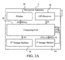
- FIGs. 2A and 2B show functional block diagrams of a navigation apparatus 3 according to one embodiment of the invention.
- the navigation apparatus 3 comprises a Global Positioning System (GPS) receiver 30, a computing unit 32, a first storage medium 34, a second storage medium 36 and a display device 38.
- the navigation apparatus 3 according to the invention is any electronic apparatus having navigation capabilities, such as a GPS mobile phone or a portable navigation device (PND).
- the navigation apparatus 3 may also comprise an independent GPS receiver and an electronic apparatus having data processing capabilities, such as a Bluetooth GPS receiver provided with a mobile phone having Bluetooth capabilities; that is, the GPS receiver is an externally connected device.
- the mobile phone may execute navigation software stored in a storage medium therein to perform the positioning method according to the invention based on GPS signals transmitted from the Bluetooth GPS receiver.
- the GPS receiver 30 receives a GPS signal P1.
- the first storage medium 34 stores a previous position-velocity-time (PVT) data P2'(t-1) and a previous map matching (MMT) result P3'(t-1).
- the second storage medium 36 stores map data P4.
- the computing unit 32 according to the GPS signal P1, the previous PVT data P2'(t-1) and the previous MMT result P3'(t-1), computes a current PVT data P2'(t).
- the computing unit 32 then, according to the map data P4 and the acquired current PVT data P2'(t), computes a current MMT result P3'(t), which includes a current position value and a current azimuth value.
- the display device 38 displays a map based on the map data P4, and the current MMT result P3'(t) acquired by the computing unit 32. Further, supposing the current PVT data P2'(t) and the current MMT result P3'(t) are valid, the computing unit 32 stores the same into the first storage medium 34 to provide the previous PVT data P2'(t-1) and the previous MMT result P3'(t-1) for a next positioning computation.
- the method according to the invention additionally takes into consideration the previous MMT result P3'(t-1) when computing the current PVT data P2'(t), so that calibration is performed to acquire a current PVT data that is closer to a correct route. Therefore, by computing the current MMT result P3'(t) with reference to the current PVT data P2'(t), the calculated positioning result is made more accurate by using the MMT P3'(t) that is closer to the correct route. Moreover, since each computed MMT result is used by a next PVT computation, errors in positioning are reduced to further avoid accumulative errors.
- FIG. 2B shows a detailed functional block diagram of the navigation apparatus 3 shown in FIG. 2A .
- the computing unit 32 comprises a PVT computing module 320 and an MMT module 322.
- the PVT computing module 320 coupled to the first storage 34 and the GPS receiver 30, computes the current PVT data P2'(t) according to the GPS signal P1, the previous PVT data P2'(t-1) and the previous MMT result P3'(t-1).
- the computing unit 32 may further comprise a routing module 324 coupled to the second storage medium 36 and the MMT module 322.
- the routing module 324 according to user-defined settings, e.g., an origin, a destination and routing requirements, and the map data P4, generates a planned route P5.
- the MMT module 322 may then calculate the current MMT result P3'(t) further according to the planned route P5.
- FIG. 3 showing a flowchart of the positioning method according to one embodiment of the invention.
- the positioning method implemented by the navigation apparatus 3 involves two main stages.
- the computing unit 32 computes a current PVT data P2'(t) as a first stage, followed by substituting the current PVT data P2'(t) into the MMT algorithm to acquire a current MMT result P3'(t) in a second stage.
- the display device 38 of the navigation apparatus 3 then displays the current position value and the current azimuth value in the current MMT result P3'(t).
- the current PVT data is computed in three different computation methods according to: 1) the previous PVT data, the MMT result and the GPS signal; 2) the previous PVT data and the GPS signal; and 3) the GPS signal.
- each of all the computation methods has prerequisite conditions, which are first established before performing subsequent computations.
- the methods of computing the current PVT data according to the invention comprise steps described below.
- Step S8 the previous PVT data and the previous MMT result are stored in Step S08.
- Step S10 a GPS signal is received.
- Step S11 the previous PVT data is read; that is, a PVT data acquired from a computation at a previous time point is read.
- Step S12 it is determined whether the previous PVT data is valid. For example, it is determined whether the previous PVT data is valid according to a root-mean-square (RMS) algorithm and a receiver autonomous integrity monitoring (RAIM) checking.
- RMS root-mean-square
- RAIM receiver autonomous integrity monitoring
- Step S160 When the result from Step S12 is negative, i.e., the previous PVT data is invalid, Step S160 is performed.
- the current PVT data is computed according to the GPS signal, as the third method for computing the current PVT data specified above. In practice, the current PVT data is computed according to the GPS signal using a least square method.
- Step S13 it is determined whether the previous MMT result, which is an MMT result acquired from a computation at a previous time point, is present. In the event that the previous MMT result is absent, Step S150 is performed, in which the current PVT data is computed according to the previous PVT data and the GPS signal, as the second method for computing the current PVT data specified above.
- Step S140 is performed to read the previous MMT result, followed by performing Step S142.
- the current PVT data is computed according to the previous PVT data, the previous MMT result and the GPS signal, as the first method for computing the PVT data specified above. For example, according to the GPS signal, a previous velocity and a previous time offset of the previous PVT data, and a previous MMT position value and a previous MMT azimuth value of the previous MMT result, the current PVT data is computed using Kalman filtering.
- Step S17 is performed to determine whether the current PVT data is valid. Similar to the method for determining whether the current PVT data is valid in the foregoing description, it is determined whether the current PVT data is valid according to an RMS algorithm and an RAIM checking. In the event that the current PVT data is invalid, the flow returns to Step S10 to restart another computation until all the acquired current PVT data are valid for subsequent MMT algorithms. In the event that the current PVT data is valid, Step S18 is performed to selectively compute a current MMT result according to the map data and the current PVT data; that is, MMT algorithms may then proceed.
- Step S144 is performed to determine whether the current PVT data is valid. In the event that the current PVT data is invalid, the flow returns to Step S 150, with description of the subsequent steps omitted for brevity. In the event that the current PVT data is valid, Step S18 is performed to selectively compute a current MMT result according to the map data and the current PVT data; that is, MMT algorithms may then proceed.
- Step S18 The MMT algorithm flow, more specifically Step S18, shall be described in detail in the following description, with reference to FIG. 4 showing a detailed flowchart of Step S18 in FIG. 3 .
- Step S180 is first performed to determine whether a current velocity of the current PVT data is greater than a predetermined velocity.
- the result from Step S180 is negative, i.e., when the current velocity is too small, the current MMT result shall not be computed, such that a previous MMT result is unavailable for reference when implementing the positioning method at a next time point.
- Step S181 is performed to define a coverage according to a current position and a predetermined radius.
- Step S182 a plurality of routes are selected from the map data according to the coverage. The selected routes are taken into account of a subsequent weighting calculation, in which distances between the routes and the current position, and differences between the azimuths of the routes and the current azimuth are taken into consideration. Note that the smaller the differences are, the more probable the current location matches a particular route.
- Step S183 is performed to determine whether a planned route is present; that is, it is determined whether the navigation apparatus 3 plans the route according to user-defined settings.
- Step S186 is performed to define a range of covered azimuth according to the current azimuth and a second angle.
- Step S183 when it is determined that a planned route is present, Step S184 is performed to determined whether any of the routes is the planned route.
- Step S185 is performed to define a range of covered azimuth according to the current azimuth and a first angle, with a distance between the current position and the planned route subtracted by a predetermined length.
- the user travels under guidance of the planned route provided by the navigation apparatus.
- the first angle is larger than the second angle.
- Step S185 and Step S186 the distances between the current position and the routes, and the range of covered azimuth, are determined.
- Step S187 is then performed to compute the current MMT result according to the distances between the current position and the routes, the range of covered azimuth, and the current azimuths of the routes, to complete the MMT algorithm.
- FIGS. 5 , 6A and 6B illustrate details of the MMT algorithm, in which the current MMT result is computed according to the distances between the current position and the routes, the range of covered azimuth, and the azimuths of the routes.
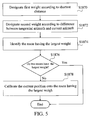
- FIG. 5 shows a detailed flowchart of Step S187 in FIG. 4 .
- FIGS. 6A and 6B show schematic diagrams corresponding to Step S1870 and Step S1872 in FIG. 5 , respectively.
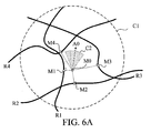
- Step S182 according to a coverage C1, a plurality of routes are selected from the map data, such as the routes R1, R2, R3 and R4 in FIG. 6A .
- Step S1870 is first performed, in which each of the routes is designated with a first weight according to a respective shortest distance between the routes and the current position.
- each of the routes R1, R2, R3 and R4 is designated with the first weight, wherein, the shorter the distance is, the larger the weight is designated.
- the route R3 is the planned route.
- the route R1 is initially designated with a largest weight since the distance between the position M1 and the current position M0 is the shortest.
- Step S185 the distance between the position M0 and the position M3 is subtracted by a predetermined length, and the route R3 consequently has a larger weight due to the reduced distance between the position M0 and the position M3. More specifically, it is probable that the route R3 has a larger first weight than the route R1 after subtracting the predetermined length from the route R3.
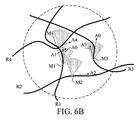
- Step S1872 it is determined whether tangential azimuths A1 to A4 at the positions M1 to M4 on the routes are situated within a coverage C2, and each of the routes R1 to R4 is designated with a second weight according to differences between the tangential azimuths A1 to A4 and the current azimuth A0.
- the tangential azimuths of the route R1, R2, R3 and R4 at the positions M1, M2, M3 and M4 are A1, A2, A3 and A4, respectively.
- the coverage C2 is compared with the tangential azimuths.
- the routes R2 and R4 are eliminated, provided that the second weight thereof is zero.
- the routes R1 and R3 are designated with a second weight.
- the tangential azimuth A1 is closer to indications of the current azimuth A0, and thus the route R1 is designated with a larger second weight.
- Step S1874 is then performed.
- Step S1874 according to the first weight and the second weight, a route having the largest weight out of all the routes is identified.
- the routes R1, R2, R3 and R4 are arranged in sequence according to respective weight, and the route having the largest weight is identified.
- Step S1876 it is determined whether two or more routes have the largest weight.
- the MMT algorithm is terminated; that is, a choice is not made between the two routes both having the largest weight to avoid selecting a wrong route.
- Step S1878 it means that the route having the largest weight is identified, and Step S1878 is performed to calibrate the current position onto the route having the largest weight.
- the calibrated position value serves for the current MMT position value of the current MMT result, and the azimuth of the route having the largest weight serves for the current MMT azimuth value of the current MMT result to complete the MMT algorithm.
- the current position is calibrated to the position M1.
- the current MMT position value is calibrated to the longitude and latitude of the position M1
- the current MMT azimuth value is calibrated to the tangential azimuth A1 at the position M1 on the route R1.
- the MMT result computed at a current time point is taken into account of a computation at a next time point, whereby the navigation apparatus is allowed to gradually calibrate according to the MMT result acquired from a previous computation and thus avoiding the issue of accumulative positioning deviation.
Abstract
Description
- The present invention relates to a positioning method, and more particularly, to a positioning method for a navigation apparatus.
- A navigation apparatus provides a user with guidance for traveling on correct routes, so that the user is free from having to constantly look at maps and watch for road signs. However, Global Positioning System (GPS) signals which the navigation system largely relies on may easily be shielded by buildings and landforms resulting in poor reception quality in certain areas. Especially when the number of visible satellites for the navigation apparatus is less than four or when the navigation system is located at a weak-signal region, the navigation apparatus becomes incapable of providing required positioning data. Under such circumstances, even if positioning signals are received, it is possible that positioning values calculated from the received GPS signals are quite different from actual values such that a current location may be misjudged.
- To improve positioning accuracy, current research has mainly focused on differential GPS (DPGS), dead reckoning (DR), inertial navigation systems (INS) and map matching (MMT) to provide a better solution.
- How a navigation apparatus of the prior art utilizes the MMT function for performing positioning calculations shall be discussed below. Referring to
FIG. 1 , anavigation apparatus 1 comprises aGPS receiver 10, acomputing unit 12, afirst storage medium 14, asecond storage medium 16 and adisplay device 18. TheGPS receiver 10 receives a GPS signal P1. Thefirst storage medium 14 stores a previous position-velocity-time (PVT) data P2(t-1). Note that PVT data contain information of position, velocity and time offset. Thesecond storage medium 16 stores map data P4. Thecomputing unit 12 computes a current PVT data P2(t) according to the GPS signal P1 and the previous PVT data P2(t-1). According to the map data P4 and the computed current PVT data P2, thecomputing unit 12 then computes a current MMT result P3(t). At this point, thedisplay device 18 displays the map data P4 and the current MMT result P3(t) acquired by thecomputing unit 12. - In an MMT algorithm, a matching operation is performed between the map data P4 and the current positioning parameter P2(t), so as to calibrate the current PVT data P2(t) onto a current route and increase positioning accuracy. However, since the positioning computations of the
navigation apparatus 1 are solely based on the previous PVT data P2(t-1) and the GPS signal P1, and due to significant errors in the imported values, thenavigation apparatus 1 can hardly calibrate the current PVT data P2(t) onto the correct route even if the current PVT data P2(t) is calibrated using MMT. In addition, since the current PVT data P2(t) acquired from the computation at a current time point includes a certain degree of error, which is accounted when the current PVT data P2(t) is imported as a previous PVT data P2(t-1), a computation at a next time point to lead to accumulative errors. More specifically, in the prior art, in addition to the computed values imported by thenavigation apparatus 1 being not considered accurate enough, the errors are also accumulated along with time such that the current MMT result P3(t) acquired is not likely to reflect a correct route. - Therefore, the present invention provides a navigation apparatus and a positioning method thereof, which are capable of increasing positioning accuracy for overcoming the aforesaid issues.
- An objective of the invention is to provide a positioning method, which imports a previous map-matching parameter for computing a current positioning parameter to acquire a more accurate position value.
- The invention is defined in
claims 1 and 11, respectively. Particular embodiments are set out in the dependent claims. - According to one embodiment of the invention, a positioning method for a navigation apparatus is provided. The method comprises: a) storing a previous positioning parameter and a previous map-matching parameter; b) receiving a positioning signal; c) reading the previous positioning parameter and the previous map-matching parameter; and d) computing a current positioning parameter according to at least one of the previous positioning parameter and the previous map-matching parameter, as well as according to the positioning signal.
- Another objective the invention is to provide a navigation system, which imports a previous positioning parameter for computing a current positioning parameter to acquire a more accurate position value.
- According to one embodiment of the invention, a navigation apparatus comprises a first storage medium, a GPS receiver and a computing unit. The first storage medium stores a previous positioning parameter and a previous map-matching parameter. The GPS receiver receives a positioning signal. The computing unit, coupled to the first storage medium and the GPS receiver, reads the previous positioning parameter and the previous map-matching parameter, and computes a current positioning parameter according to the positioning signal, the previous positioning parameter and the previous map-matching parameter.
- In the prior art, computations for a current positioning parameter require a previous positioning parameter and a positioning signal. Supposing the previous positioning parameter or the positioning signal is deviated from actual position value, the computed current positioning parameter is bound to deviate even further away from the actual position value due to accumulative deviation. Therefore, because a map-matching parameter is a computation result of calibration and matching using a map data, the invention adopts the map-matching parameter for performing the computation in conjunction with the previous positioning parameter and the positioning signal to acquire a more accurate current positioning parameter. In a subsequent MMT algorithm, a more accurate map-matching parameter, i.e., a more accurate position value, is acquired. Further, according to the invention, the map-matching parameter computed at a current time point is taken into account during a computation at a next time point, whereby the navigation apparatus is allowed to gradually calibrate according to the map-matching parameter acquired from a previous computation and thus avoid the issue of accumulative positioning deviation.
- The present invention will become more readily apparent to those ordinarily skilled in the art after reviewing the following detailed description and accompanying drawings, in which:
-
FIG. 1 is a functional block diagram of a navigation apparatus of the -
FIG 2A is a detailed functional block diagram of a navigation apparatus according to one embodiment of the invention; -
FIG. 2B is a detailed functional block diagram of the navigation apparatus inFIG. 2A ; -
FIG. 3 is a flowchart of a positioning method according to one embodiment of the invention; -
FIG. 4 is a detailed flowchart of Step S18 inFIG. 3 ; -
FIG. 5 is a detailed flowchart of Step S187 inFIG. 4 ; -
FIG. 6A is a schematic diagram corresponding to Step S1870 inFIG. 5 ; and -
FIG. 6B is a schematic diagram corresponding to Step S1872 inFIG. 5 . -
FIGs. 2A and2B show functional block diagrams of anavigation apparatus 3 according to one embodiment of the invention. As shown, thenavigation apparatus 3 comprises a Global Positioning System (GPS)receiver 30, acomputing unit 32, afirst storage medium 34, asecond storage medium 36 and adisplay device 38. Thenavigation apparatus 3 according to the invention is any electronic apparatus having navigation capabilities, such as a GPS mobile phone or a portable navigation device (PND). Thenavigation apparatus 3 may also comprise an independent GPS receiver and an electronic apparatus having data processing capabilities, such as a Bluetooth GPS receiver provided with a mobile phone having Bluetooth capabilities; that is, the GPS receiver is an externally connected device. The mobile phone may execute navigation software stored in a storage medium therein to perform the positioning method according to the invention based on GPS signals transmitted from the Bluetooth GPS receiver. - The
GPS receiver 30 receives a GPS signal P1. Thefirst storage medium 34 stores a previous position-velocity-time (PVT) data P2'(t-1) and a previous map matching (MMT) result P3'(t-1). Thesecond storage medium 36 stores map data P4. Thecomputing unit 32, according to the GPS signal P1, the previous PVT data P2'(t-1) and the previous MMT result P3'(t-1), computes a current PVT data P2'(t). Thecomputing unit 32 then, according to the map data P4 and the acquired current PVT data P2'(t), computes a current MMT result P3'(t), which includes a current position value and a current azimuth value. At this point, thedisplay device 38 displays a map based on the map data P4, and the current MMT result P3'(t) acquired by thecomputing unit 32. Further, supposing the current PVT data P2'(t) and the current MMT result P3'(t) are valid, thecomputing unit 32 stores the same into thefirst storage medium 34 to provide the previous PVT data P2'(t-1) and the previous MMT result P3'(t-1) for a next positioning computation. - Compared to the prior art shown in
FIG. 1 , the method according to the invention additionally takes into consideration the previous MMT result P3'(t-1) when computing the current PVT data P2'(t), so that calibration is performed to acquire a current PVT data that is closer to a correct route. Therefore, by computing the current MMT result P3'(t) with reference to the current PVT data P2'(t), the calculated positioning result is made more accurate by using the MMT P3'(t) that is closer to the correct route. Moreover, since each computed MMT result is used by a next PVT computation, errors in positioning are reduced to further avoid accumulative errors. -
FIG. 2B shows a detailed functional block diagram of thenavigation apparatus 3 shown inFIG. 2A . Thecomputing unit 32 comprises aPVT computing module 320 and anMMT module 322. ThePVT computing module 320, coupled to thefirst storage 34 and theGPS receiver 30, computes the current PVT data P2'(t) according to the GPS signal P1, the previous PVT data P2'(t-1) and the previous MMT result P3'(t-1). TheMMT module 322, coupled to thesecond storage medium 36 and thePVT computing module 320, computes the current MMT result P3'(t) according to the current PVT data P2'(t) and the map data P4. - The
computing unit 32 may further comprise arouting module 324 coupled to thesecond storage medium 36 and theMMT module 322. Therouting module 324, according to user-defined settings, e.g., an origin, a destination and routing requirements, and the map data P4, generates a planned route P5. Provided that the user programs thenavigation apparatus 3 for route planning, theMMT module 322 may then calculate the current MMT result P3'(t) further according to the planned route P5. - To better understand the positioning method implemented by the
navigation apparatus 3 according to the invention, reference is made toFIG. 3 showing a flowchart of the positioning method according to one embodiment of the invention. - The positioning method implemented by the
navigation apparatus 3 involves two main stages. Thecomputing unit 32 computes a current PVT data P2'(t) as a first stage, followed by substituting the current PVT data P2'(t) into the MMT algorithm to acquire a current MMT result P3'(t) in a second stage. Thedisplay device 38 of thenavigation apparatus 3 then displays the current position value and the current azimuth value in the current MMT result P3'(t). - Dependent on different circumstances, the current PVT data is computed in three different computation methods according to: 1) the previous PVT data, the MMT result and the GPS signal; 2) the previous PVT data and the GPS signal; and 3) the GPS signal. However, each of all the computation methods has prerequisite conditions, which are first established before performing subsequent computations. With reference to
FIG. 3 , the methods of computing the current PVT data according to the invention comprise steps described below. - After Start, the previous PVT data and the previous MMT result are stored in Step S08.
- In Step S10, a GPS signal is received.
- In Step S11, the previous PVT data is read; that is, a PVT data acquired from a computation at a previous time point is read.
- In Step S12, it is determined whether the previous PVT data is valid. For example, it is determined whether the previous PVT data is valid according to a root-mean-square (RMS) algorithm and a receiver autonomous integrity monitoring (RAIM) checking.
- When the result from Step S12 is negative, i.e., the previous PVT data is invalid, Step S160 is performed. In Step S160, the current PVT data is computed according to the GPS signal, as the third method for computing the current PVT data specified above. In practice, the current PVT data is computed according to the GPS signal using a least square method.
- When the result from Step S12 is affirmative, i.e., the previous PVT data is valid, Step S13 is performed. In Step S13, it is determined whether the previous MMT result, which is an MMT result acquired from a computation at a previous time point, is present. In the event that the previous MMT result is absent, Step S150 is performed, in which the current PVT data is computed according to the previous PVT data and the GPS signal, as the second method for computing the current PVT data specified above.
- When the result from S13 is affirmative, i.e., the previous MMT result is present, Step S140 is performed to read the previous MMT result, followed by performing Step S142. In Step S142, the current PVT data is computed according to the previous PVT data, the previous MMT result and the GPS signal, as the first method for computing the PVT data specified above. For example, according to the GPS signal, a previous velocity and a previous time offset of the previous PVT data, and a previous MMT position value and a previous MMT azimuth value of the previous MMT result, the current PVT data is computed using Kalman filtering.
- After performing the second or the third method for computing the current PVT data, that is, after performing Step S150 or Step S160, Step S17 is performed to determine whether the current PVT data is valid. Similar to the method for determining whether the current PVT data is valid in the foregoing description, it is determined whether the current PVT data is valid according to an RMS algorithm and an RAIM checking. In the event that the current PVT data is invalid, the flow returns to Step S10 to restart another computation until all the acquired current PVT data are valid for subsequent MMT algorithms. In the event that the current PVT data is valid, Step S18 is performed to selectively compute a current MMT result according to the map data and the current PVT data; that is, MMT algorithms may then proceed.
- Further, after performing
Step S 142 of the first method for computing the current PVT data, Step S144 is performed to determine whether the current PVT data is valid. In the event that the current PVT data is invalid, the flow returns to StepS 150, with description of the subsequent steps omitted for brevity. In the event that the current PVT data is valid, Step S18 is performed to selectively compute a current MMT result according to the map data and the current PVT data; that is, MMT algorithms may then proceed. - The flow for computing the current PVT data in the positioning method is as discussed above. To compute the current MMT result, which is for computing a final position result, the current PVT data need be substituted into the MMT algorithm. The MMT algorithm flow, more specifically Step S18, shall be described in detail in the following description, with reference to
FIG. 4 showing a detailed flowchart of Step S18 inFIG. 3 . - In the MMT algorithm, Step S180 is first performed to determine whether a current velocity of the current PVT data is greater than a predetermined velocity. When the result from Step S180 is negative, i.e., when the current velocity is too small, the current MMT result shall not be computed, such that a previous MMT result is unavailable for reference when implementing the positioning method at a next time point.
- When the result from Step S180 is affirmative, i.e., when the current velocity of the current PVT data is larger than the predetermined velocity, Step S181 is performed to define a coverage according to a current position and a predetermined radius. In Step S182, a plurality of routes are selected from the map data according to the coverage. The selected routes are taken into account of a subsequent weighting calculation, in which distances between the routes and the current position, and differences between the azimuths of the routes and the current azimuth are taken into consideration. Note that the smaller the differences are, the more probable the current location matches a particular route.
- Next, Step S183 is performed to determine whether a planned route is present; that is, it is determined whether the
navigation apparatus 3 plans the route according to user-defined settings. When the result from Step S183 is affirmative, it means that a planned route is present. When the result is negative, Step S186 is performed to define a range of covered azimuth according to the current azimuth and a second angle. - In Step S183, when it is determined that a planned route is present, Step S184 is performed to determined whether any of the routes is the planned route. When the result from Step S184 is affirmative, Step S185 is performed to define a range of covered azimuth according to the current azimuth and a first angle, with a distance between the current position and the planned route subtracted by a predetermined length. In normal circumstances, the user travels under guidance of the planned route provided by the navigation apparatus. To match the current position as much as possible to the planned route, not only is the distance between the current position and the planned route subtracted by a predetermined length, but error tolerance of the current azimuth is increased, such that the planned route is predominant in the subsequent weighting calculation. Therefore, in Step S185 and Step S186, the first angle is larger than the second angle.
- In Step S185 and Step S186, the distances between the current position and the routes, and the range of covered azimuth, are determined. Step S187 is then performed to compute the current MMT result according to the distances between the current position and the routes, the range of covered azimuth, and the current azimuths of the routes, to complete the MMT algorithm.
-
FIGS. 5 ,6A and6B illustrate details of the MMT algorithm, in which the current MMT result is computed according to the distances between the current position and the routes, the range of covered azimuth, and the azimuths of the routes.FIG. 5 shows a detailed flowchart of Step S187 inFIG. 4 .FIGS. 6A and6B show schematic diagrams corresponding to Step S1870 and Step S1872 inFIG. 5 , respectively. - In Step S182, according to a coverage C1, a plurality of routes are selected from the map data, such as the routes R1, R2, R3 and R4 in
FIG. 6A . - Step S1870 is first performed, in which each of the routes is designated with a first weight according to a respective shortest distance between the routes and the current position. For example, referring to
FIG. 6A , according to distances between a current position M0 and positions M1, M2, M3 and M4 on the routes, each of the routes R1, R2, R3 and R4 is designated with the first weight, wherein, the shorter the distance is, the larger the weight is designated. Suppose the route R3 is the planned route. In this embodiment, the route R1 is initially designated with a largest weight since the distance between the position M1 and the current position M0 is the shortest. However, in Step S185, the distance between the position M0 and the position M3 is subtracted by a predetermined length, and the route R3 consequently has a larger weight due to the reduced distance between the position M0 and the position M3. More specifically, it is probable that the route R3 has a larger first weight than the route R1 after subtracting the predetermined length from the route R3. - In the next Step S1872, it is determined whether tangential azimuths A1 to A4 at the positions M1 to M4 on the routes are situated within a coverage C2, and each of the routes R1 to R4 is designated with a second weight according to differences between the tangential azimuths A1 to A4 and the current azimuth A0. Referring to
FIG. 6B , the tangential azimuths of the route R1, R2, R3 and R4 at the positions M1, M2, M3 and M4 are A1, A2, A3 and A4, respectively. The coverage C2 is compared with the tangential azimuths. Since the tangential azimuths A2 and A4 are not within the coverage C2, the routes R2 and R4 are eliminated, provided that the second weight thereof is zero. According to respective differences between the tangential azimuths A1 and A3, and the current azimuth A0, the routes R1 and R3 are designated with a second weight. In this embodiment, as shown inFIG. 6B , the tangential azimuth A1 is closer to indications of the current azimuth A0, and thus the route R1 is designated with a larger second weight. - Step S1874 is then performed. In Step S1874, according to the first weight and the second weight, a route having the largest weight out of all the routes is identified. By taking into consideration both the first and second weights, the routes R1, R2, R3 and R4 are arranged in sequence according to respective weight, and the route having the largest weight is identified.
- In the next Step S1876, it is determined whether two or more routes have the largest weight. When the result from Step S1876 is affirmative, the MMT algorithm is terminated; that is, a choice is not made between the two routes both having the largest weight to avoid selecting a wrong route. When the result is negative, it means that the route having the largest weight is identified, and Step S1878 is performed to calibrate the current position onto the route having the largest weight. The calibrated position value serves for the current MMT position value of the current MMT result, and the azimuth of the route having the largest weight serves for the current MMT azimuth value of the current MMT result to complete the MMT algorithm. Referring to
FIG. 6B , supposing the route R1 has the largest weight, the current position is calibrated to the position M1. To be exact, the current MMT position value is calibrated to the longitude and latitude of the position M1, and the current MMT azimuth value is calibrated to the tangential azimuth A1 at the position M1 on the route R1. - In the prior art, computations for a current PVT data require a previous PVT data and a GPS signal. Supposing the previous PVT data or the GPS signal is deviated from the actual position value, the computed current PVT data is bound to deviate even further away from the actual position value due to accumulative deviation. In continuation of the foregoing description, since an MMT result is a computation result of calibration and matching using the map data, the invention adopts the MMT for performing computation in conjunction with the previous PVT data and the GPS signal to acquire a more accurate current PVT data. In a subsequent MMT algorithm, a more accurate MMT result, i.e., a more accurate position value, is acquired. Further, according to the invention, the MMT result computed at a current time point is taken into account of a computation at a next time point, whereby the navigation apparatus is allowed to gradually calibrate according to the MMT result acquired from a previous computation and thus avoiding the issue of accumulative positioning deviation.
- While the invention has been described in terms of what is presently considered to be the most practical and preferred embodiments, it is to be understood that the invention needs not to be limited to the above embodiments. On the contrary, it is intended to cover various modifications and similar arrangements included within the spirit and scope of the appended claims which are to be accorded with the broadest interpretation so as to encompass all such modifications and similar structures.
Claims (17)
- A positioning method for a navigation apparatus (3), comprising steps of:a) storing (S08) a previous positioning parameter (P2'(t-1)) and a previous map-matching parameter (P3'(t-1));b) receiving (S10) a positioning signal (P1);c) reading (S11, S140) the previous positioning parameter (P2'(t-1)) and the previous map-matching parameter (P3'(t-1)); andd) determining (S142) a current positioning parameter (P2'(t)) according to the positioning signal (P1), the previous positioning parameter (P2'(t-1)) and the previous map-matching parameter (P3'(t-1)).
- The positioning method as claimed in claim 1, wherein the step (d) is computing (S142) the current positioning parameter (P2'(t)) according to the positioning signal (P1), a previous velocity and a previous time offset associated with the previous positioning parameter (P2'(t-1)), and a previous MMT position value and a previous MMT azimuth value associated with the previous map-matching parameter (P3'(t-1)).
- The positioning method as claimed in claim 1 or 2, wherein the step (c) further comprises steps of:c1) determining (S12) whether the previous positioning parameter (P2'(t-1)) is valid;wherein, when it is determined the previous positioning parameter (P2'(t-1)) is invalid, the method further comprising:e) determining (S160) an initial positioning parameter, according to the positioning signal (P1) received by the navigation apparatus (3).
- The positioning method as claimed in claim 1, 2 or 3, wherein the step (c) further comprises steps of:c1) determining (S13) whether the previous map-matching parameter (P3'(t-1)) is present;wherein, when it is determined the previous map-matching parameter (P3'(t-1)) is absent, the current positioning parameter (P2'(t)) is computed (S150) in the step (d) according to the previous positioning parameter (P2'(t-1)) and the positioning signal (P1).
- The positioning method as claimed in any of claims 1 to 4, further comprising:f) determining (S144) whether the current positioning parameter (P2'(t)) is valid;wherein, when it is determined the current positioning parameter (P2'(t)) is invalid, the current positioning parameter is computed (S150) in the step (d) according to the previous positioning parameter (P2'(t-1)) and the positioning signal (P1).
- The positioning method as claimed in any of claims 1 to 5, the navigation apparatus (3) comprising a map data (P4), the method further comprising:g) selectively computing (S18) the current map-matching parameter (P3'(t)) according to the map data (P4) and the current positioning parameter (P2'(t)).
- The positioning method as claimed in claim 6, the positioning parameter (P2'(t)) comprising a current position value and a current azimuth value, the step (g) further comprising steps of:g1) defining a coverage (S181) according to the current position value and a predetermined radius, and selecting (S182) a plurality of routes from the map data (P4) according to the coverage;g2) determining (S183) whether a planned route is present;g3) determining (S184) whether any of the routes is the planned route when the planned route is present;g4) when the planned route is identified from the routes, defining (S185) a range of a covered azimuth according to the current azimuth value and a first angle, and subtracting a distance between the current position value and the planned route by a predetermined length;g5) when the planned route is absent or unidentified from the routes, defining (S186) a range of covered azimuth according to the current azimuth value and a second angle; andg6) determining (S187) the current map-matching parameter (P3'(t)) according to the current position value, the routes, the current azimuth value and the range of covered azimuth;wherein, the first angle is larger than the second angle.
- The positioning method as claimed in claim 7, wherein the step (g6) comprises a step of:g6-1) setting (S1870, S1872) a weight of each of the routes according to the current position value, the current azimuth value, the routes and the range of covered azimuth.
- The positioning method as claimed in claim 8, further comprising a step of:g6-2) selecting (S1874) a route having the largest weight; calibrating (S1878) the current position value to the selected route; and using the calibrated position value as a current position value of the current map-matching parameter (P3'(t)), and the azimuth value of the selected route as a current azimuth value of the current map-matching parameter.
- The positioning method as claimed in claim 8, wherein the step (g6-1) comprises steps of:g6-1-1) designating (S1870) a first weight to each of the routes according to respective distances between the routes and the current position value;g6-1-2) matching the azimuth value of each of the routes with the range of covered azimuth, and designating (S1872) a second weight to each of the routes according to respective differences between the azimuth values of each of the routes and the current azimuth value; andg6-1-3) setting the weight of each of the routes according to the first weight and the second weight of each of the routes.
- A navigation apparatus (3), comprising:a first storage medium (34), stored with a previous positioning parameter data (P2'(t-1)) and a previous map-matching parameter (P3'(t-1));a receiver (30), for receiving a positioning signal (P1); anda computing unit (32), coupled to the first storage medium (34) and the receiver (30), for reading the previous positioning parameter (P2'(t-1)) and the previous map-matching parameter (P3'(t-1)), and for determining a current positioning parameter (P2'(t)) according to the positioning signal (P1), the previous positioning parameter and the previous map-matching parameter.
- The navigation apparatus as claimed in claim 11, wherein the computing unit (32) computes the current positioning parameter (P2'(t)) according to the positioning signal (P1), a previous velocity and a previous time offset of the previous positioning parameter, and a previous MMT position value and a previous MMT azimuth value of the previous map-matching parameter (P3'(t-1)).
- The navigation apparatus as claimed in claim 11 or 12, wherein the computing unit (32) computes the current positioning parameter (P2'(t)) using a Kalman filter.
- The navigation apparatus as claimed in claim 11, 12 or 13, further comprising:a second storage medium (36), for storing a map data (P4), and selectively computing the current map-matching parameter (P3'(t)) according to the map data (P4) and the current positioning parameter (P2'(t)).
- The navigation apparatus as claimed in claim 14, wherein the computing unit (32) comprises:a first computing module (PVT module, 320), coupled to the first storage medium (34) and the receiver (30), for computing the current positioning parameter (P2'(t)) according to the positioning signal (P1), the previous positioning parameter (P2'(t-1)) and the previous map-matching parameter (P3'(t-1)); anda second module (MMT module, 322), coupled to the second storage medium (36) and the PVT computing module (320), for computing the current map-matching parameter (P3'(t)) according to the current positioning parameter (P2'(t)) and the map data (P4).
- The navigation apparatus as claimed in claim 15, wherein the computing unit (32) further comprises:a third module (324), coupled to the second storage medium (36) and the MMT module (322), for generating a planned route;wherein, the second module (322) computes the current map-matching parameter (P3'(t)) further according to the planned route.
- The navigation apparatus as claimed in any of claims 12 to 16, wherein when the previous positioning parameter (P2'(t-1)) is invalid, the computing unit (32) computing an initial positioning parameter according to the positioning signal (P1) by means of a root-mean-square (RMS) algorithm.
Applications Claiming Priority (1)
| Application Number | Priority Date | Filing Date | Title |
|---|---|---|---|
| TW097123459A TWI378223B (en) | 2008-06-24 | 2008-06-24 | Navigation apparatus and positioning method thereof |
Publications (3)
| Publication Number | Publication Date |
|---|---|
| EP2146183A2 true EP2146183A2 (en) | 2010-01-20 |
| EP2146183A3 EP2146183A3 (en) | 2011-01-19 |
| EP2146183B1 EP2146183B1 (en) | 2013-04-10 |
Family
ID=41130479
Family Applications (1)
| Application Number | Title | Priority Date | Filing Date |
|---|---|---|---|
| EP09007673.8A Not-in-force EP2146183B1 (en) | 2008-06-24 | 2009-06-10 | Navigation apparatus and positioning method thereof |
Country Status (4)
| Country | Link |
|---|---|
| US (1) | US8214149B2 (en) |
| EP (1) | EP2146183B1 (en) |
| RU (1) | RU2515959C2 (en) |
| TW (1) | TWI378223B (en) |
Cited By (2)
| Publication number | Priority date | Publication date | Assignee | Title |
|---|---|---|---|---|
| CN103033832A (en) * | 2011-09-30 | 2013-04-10 | 上海博泰悦臻电子设备制造有限公司 | Navigation system and road matching method and device |
| CN104019821A (en) * | 2013-02-28 | 2014-09-03 | 腾讯科技(深圳)有限公司 | Electronic map matching method and device |
Families Citing this family (4)
| Publication number | Priority date | Publication date | Assignee | Title |
|---|---|---|---|---|
| TWI485421B (en) | 2012-12-17 | 2015-05-21 | Ind Tech Res Inst | Map matching device, system and method |
| US9959208B2 (en) * | 2015-06-02 | 2018-05-01 | Goodrich Corporation | Parallel caching architecture and methods for block-based data processing |
| EP3339807B1 (en) * | 2016-12-20 | 2024-03-13 | HERE Global B.V. | An apparatus and associated methods for determining the location of a vehicle |
| CN108922372A (en) * | 2018-05-18 | 2018-11-30 | 霍州煤电集团吕梁山煤电有限公司方山木瓜煤矿 | A kind of localization method of customized map and coordinate based on mobile terminal |
Citations (2)
| Publication number | Priority date | Publication date | Assignee | Title |
|---|---|---|---|---|
| US20020177950A1 (en) | 2001-05-24 | 2002-11-28 | Davies F. Bryan | Satellite based on-board vehicle navigation system including predictive filtering and map-matching to reduce errors in a vehicular position |
| US20080091347A1 (en) | 2006-10-16 | 2008-04-17 | Eric Tashiro | Map matching method and apparatus for navigation system |
Family Cites Families (13)
| Publication number | Priority date | Publication date | Assignee | Title |
|---|---|---|---|---|
| US5862511A (en) * | 1995-12-28 | 1999-01-19 | Magellan Dis, Inc. | Vehicle navigation system and method |
| US6327534B1 (en) * | 1996-09-30 | 2001-12-04 | Qualcomm Incorporated | Unambiguous position determination using two low-earth orbit satellites |
| US5948043A (en) * | 1996-11-08 | 1999-09-07 | Etak, Inc. | Navigation system using GPS data |
| JP2001264099A (en) * | 2000-03-15 | 2001-09-26 | Honda Motor Co Ltd | Navigation system for vehicle |
| US6622090B2 (en) | 2000-09-26 | 2003-09-16 | American Gnc Corporation | Enhanced inertial measurement unit/global positioning system mapping and navigation process |
| US6577952B2 (en) * | 2001-01-08 | 2003-06-10 | Motorola, Inc. | Position and heading error-correction method and apparatus for vehicle navigation systems |
| JP4566538B2 (en) * | 2003-09-24 | 2010-10-20 | 富士フイルム株式会社 | Method for producing dope |
| WO2005076031A2 (en) | 2003-10-06 | 2005-08-18 | Sirf Technology, Inc. | A system and method for augmenting a satellite-based navigation solution |
| US20070162224A1 (en) * | 2006-01-12 | 2007-07-12 | Gang Luo | Systems and method for providing a navigation route on a geographical map based on a road portion selected by a pointer placed thereon |
| JP4832903B2 (en) * | 2006-01-17 | 2011-12-07 | アルパイン株式会社 | Navigation device and current position calculation method |
| JP4716886B2 (en) * | 2006-02-06 | 2011-07-06 | アルパイン株式会社 | Method of determining advancing angle of position calculating device |
| JP4124249B2 (en) * | 2006-07-25 | 2008-07-23 | トヨタ自動車株式会社 | Positioning device, navigation system |
| US20100042322A1 (en) * | 2006-12-13 | 2010-02-18 | Chang-Hee Won | Modular navigation system and methods |
-
2008
- 2008-06-24 TW TW097123459A patent/TWI378223B/en active
-
2009
- 2009-06-08 US US12/480,140 patent/US8214149B2/en active Active
- 2009-06-10 EP EP09007673.8A patent/EP2146183B1/en not_active Not-in-force
- 2009-06-23 RU RU2009124047/28A patent/RU2515959C2/en not_active IP Right Cessation
Patent Citations (2)
| Publication number | Priority date | Publication date | Assignee | Title |
|---|---|---|---|---|
| US20020177950A1 (en) | 2001-05-24 | 2002-11-28 | Davies F. Bryan | Satellite based on-board vehicle navigation system including predictive filtering and map-matching to reduce errors in a vehicular position |
| US20080091347A1 (en) | 2006-10-16 | 2008-04-17 | Eric Tashiro | Map matching method and apparatus for navigation system |
Cited By (3)
| Publication number | Priority date | Publication date | Assignee | Title |
|---|---|---|---|---|
| CN103033832A (en) * | 2011-09-30 | 2013-04-10 | 上海博泰悦臻电子设备制造有限公司 | Navigation system and road matching method and device |
| CN103033832B (en) * | 2011-09-30 | 2015-10-07 | 上海博泰悦臻电子设备制造有限公司 | Navigational system and road matching method and device |
| CN104019821A (en) * | 2013-02-28 | 2014-09-03 | 腾讯科技(深圳)有限公司 | Electronic map matching method and device |
Also Published As
| Publication number | Publication date |
|---|---|
| US8214149B2 (en) | 2012-07-03 |
| EP2146183A3 (en) | 2011-01-19 |
| RU2009124047A (en) | 2010-12-27 |
| TW201000861A (en) | 2010-01-01 |
| US20090319183A1 (en) | 2009-12-24 |
| EP2146183B1 (en) | 2013-04-10 |
| TWI378223B (en) | 2012-12-01 |
| RU2515959C2 (en) | 2014-05-20 |
Similar Documents
| Publication | Publication Date | Title |
|---|---|---|
| JP5142047B2 (en) | Navigation device and navigation program | |
| JP5152677B2 (en) | Navigation device and navigation program | |
| JP5051550B2 (en) | Navigation device and navigation program | |
| US7565241B2 (en) | Automobile navigation system and road map update system | |
| JP4728095B2 (en) | Navigation device | |
| EP1571460B1 (en) | Satellite positioning apparatus and current position determining method | |
| KR100713459B1 (en) | Method for determinig deviation of the path of a mobile in navigation system and navigation system | |
| JP5039455B2 (en) | Navigation device | |
| US20080021638A1 (en) | Navigation system | |
| JP2007206010A (en) | Method for determining travel angle of position calculator | |
| US8214149B2 (en) | Navigation apparatus and positioning method thereof | |
| JP6055185B2 (en) | Determining the position of the navigation device | |
| JP2006275619A (en) | Altitude calculation system and navigation system | |
| KR100526571B1 (en) | Off-board navigation system and method for calibrating error using the same | |
| JP4835413B2 (en) | Vehicle navigation device | |
| JP2010151546A (en) | Navigation device and program for navigation | |
| WO2008140146A1 (en) | Method and apparatus for decide turn condition using sensor | |
| JP4646720B2 (en) | Navigation device | |
| JP2003207342A (en) | Map information updating device and system | |
| EP2565676A1 (en) | Apparatus and method for correcting position information of portable terminal in multi-path zone | |
| JP4738196B2 (en) | Method for determining error circle of position calculation device | |
| JP2001289647A (en) | Navigator | |
| JP2001272238A (en) | Navigation device and storage medium | |
| JP2003344065A (en) | On-vehicle navigation apparatus, navigation method, and program | |
| JPH08313283A (en) | Method and apparatus for navigation |
Legal Events
| Date | Code | Title | Description |
|---|---|---|---|
| PUAI | Public reference made under article 153(3) epc to a published international application that has entered the european phase |
Free format text: ORIGINAL CODE: 0009012 |
|
| AK | Designated contracting states |
Kind code of ref document: A2 Designated state(s): AT BE BG CH CY CZ DE DK EE ES FI FR GB GR HR HU IE IS IT LI LT LU LV MC MK MT NL NO PL PT RO SE SI SK TR |
|
| AX | Request for extension of the european patent |
Extension state: AL BA RS |
|
| PUAL | Search report despatched |
Free format text: ORIGINAL CODE: 0009013 |
|
| AK | Designated contracting states |
Kind code of ref document: A3 Designated state(s): AT BE BG CH CY CZ DE DK EE ES FI FR GB GR HR HU IE IS IT LI LT LU LV MC MK MT NL NO PL PT RO SE SI SK TR |
|
| AX | Request for extension of the european patent |
Extension state: AL BA RS |
|
| 17P | Request for examination filed |
Effective date: 20110518 |
|
| 17Q | First examination report despatched |
Effective date: 20110629 |
|
| REG | Reference to a national code |
Ref country code: DE Ref legal event code: R079 Ref document number: 602009014760 Country of ref document: DE Free format text: PREVIOUS MAIN CLASS: G01C0021000000 Ipc: G01C0021300000 |
|
| GRAP | Despatch of communication of intention to grant a patent |
Free format text: ORIGINAL CODE: EPIDOSNIGR1 |
|
| RIC1 | Information provided on ipc code assigned before grant |
Ipc: G01C 21/30 20060101AFI20121112BHEP Ipc: G01S 19/50 20100101ALI20121112BHEP |
|
| GRAS | Grant fee paid |
Free format text: ORIGINAL CODE: EPIDOSNIGR3 |
|
| GRAA | (expected) grant |
Free format text: ORIGINAL CODE: 0009210 |
|
| AK | Designated contracting states |
Kind code of ref document: B1 Designated state(s): AT BE BG CH CY CZ DE DK EE ES FI FR GB GR HR HU IE IS IT LI LT LU LV MC MK MT NL NO PL PT RO SE SI SK TR |
|
| REG | Reference to a national code |
Ref country code: GB Ref legal event code: FG4D |
|
| REG | Reference to a national code |
Ref country code: AT Ref legal event code: REF Ref document number: 606237 Country of ref document: AT Kind code of ref document: T Effective date: 20130415 Ref country code: CH Ref legal event code: EP |
|
| REG | Reference to a national code |
Ref country code: IE Ref legal event code: FG4D |
|
| REG | Reference to a national code |
Ref country code: DE Ref legal event code: R096 Ref document number: 602009014760 Country of ref document: DE Effective date: 20130606 |
|
| PG25 | Lapsed in a contracting state [announced via postgrant information from national office to epo] |
Ref country code: SI Free format text: LAPSE BECAUSE OF FAILURE TO SUBMIT A TRANSLATION OF THE DESCRIPTION OR TO PAY THE FEE WITHIN THE PRESCRIBED TIME-LIMIT Effective date: 20130410 |
|
| REG | Reference to a national code |
Ref country code: AT Ref legal event code: MK05 Ref document number: 606237 Country of ref document: AT Kind code of ref document: T Effective date: 20130410 |
|
| REG | Reference to a national code |
Ref country code: LT Ref legal event code: MG4D Ref country code: NL Ref legal event code: VDEP Effective date: 20130410 |
|
| PG25 | Lapsed in a contracting state [announced via postgrant information from national office to epo] |
Ref country code: NO Free format text: LAPSE BECAUSE OF FAILURE TO SUBMIT A TRANSLATION OF THE DESCRIPTION OR TO PAY THE FEE WITHIN THE PRESCRIBED TIME-LIMIT Effective date: 20130710 Ref country code: LT Free format text: LAPSE BECAUSE OF FAILURE TO SUBMIT A TRANSLATION OF THE DESCRIPTION OR TO PAY THE FEE WITHIN THE PRESCRIBED TIME-LIMIT Effective date: 20130410 Ref country code: ES Free format text: LAPSE BECAUSE OF FAILURE TO SUBMIT A TRANSLATION OF THE DESCRIPTION OR TO PAY THE FEE WITHIN THE PRESCRIBED TIME-LIMIT Effective date: 20130721 Ref country code: SE Free format text: LAPSE BECAUSE OF FAILURE TO SUBMIT A TRANSLATION OF THE DESCRIPTION OR TO PAY THE FEE WITHIN THE PRESCRIBED TIME-LIMIT Effective date: 20130410 Ref country code: PT Free format text: LAPSE BECAUSE OF FAILURE TO SUBMIT A TRANSLATION OF THE DESCRIPTION OR TO PAY THE FEE WITHIN THE PRESCRIBED TIME-LIMIT Effective date: 20130812 Ref country code: GR Free format text: LAPSE BECAUSE OF FAILURE TO SUBMIT A TRANSLATION OF THE DESCRIPTION OR TO PAY THE FEE WITHIN THE PRESCRIBED TIME-LIMIT Effective date: 20130711 Ref country code: FI Free format text: LAPSE BECAUSE OF FAILURE TO SUBMIT A TRANSLATION OF THE DESCRIPTION OR TO PAY THE FEE WITHIN THE PRESCRIBED TIME-LIMIT Effective date: 20130410 Ref country code: AT Free format text: LAPSE BECAUSE OF FAILURE TO SUBMIT A TRANSLATION OF THE DESCRIPTION OR TO PAY THE FEE WITHIN THE PRESCRIBED TIME-LIMIT Effective date: 20130410 Ref country code: IS Free format text: LAPSE BECAUSE OF FAILURE TO SUBMIT A TRANSLATION OF THE DESCRIPTION OR TO PAY THE FEE WITHIN THE PRESCRIBED TIME-LIMIT Effective date: 20130810 Ref country code: BE Free format text: LAPSE BECAUSE OF FAILURE TO SUBMIT A TRANSLATION OF THE DESCRIPTION OR TO PAY THE FEE WITHIN THE PRESCRIBED TIME-LIMIT Effective date: 20130410 Ref country code: NL Free format text: LAPSE BECAUSE OF FAILURE TO SUBMIT A TRANSLATION OF THE DESCRIPTION OR TO PAY THE FEE WITHIN THE PRESCRIBED TIME-LIMIT Effective date: 20130410 |
|
| PG25 | Lapsed in a contracting state [announced via postgrant information from national office to epo] |
Ref country code: PL Free format text: LAPSE BECAUSE OF FAILURE TO SUBMIT A TRANSLATION OF THE DESCRIPTION OR TO PAY THE FEE WITHIN THE PRESCRIBED TIME-LIMIT Effective date: 20130410 Ref country code: LV Free format text: LAPSE BECAUSE OF FAILURE TO SUBMIT A TRANSLATION OF THE DESCRIPTION OR TO PAY THE FEE WITHIN THE PRESCRIBED TIME-LIMIT Effective date: 20130410 Ref country code: CY Free format text: LAPSE BECAUSE OF FAILURE TO SUBMIT A TRANSLATION OF THE DESCRIPTION OR TO PAY THE FEE WITHIN THE PRESCRIBED TIME-LIMIT Effective date: 20130410 Ref country code: HR Free format text: LAPSE BECAUSE OF FAILURE TO SUBMIT A TRANSLATION OF THE DESCRIPTION OR TO PAY THE FEE WITHIN THE PRESCRIBED TIME-LIMIT Effective date: 20130410 Ref country code: BG Free format text: LAPSE BECAUSE OF FAILURE TO SUBMIT A TRANSLATION OF THE DESCRIPTION OR TO PAY THE FEE WITHIN THE PRESCRIBED TIME-LIMIT Effective date: 20130710 |
|
| PG25 | Lapsed in a contracting state [announced via postgrant information from national office to epo] |
Ref country code: EE Free format text: LAPSE BECAUSE OF FAILURE TO SUBMIT A TRANSLATION OF THE DESCRIPTION OR TO PAY THE FEE WITHIN THE PRESCRIBED TIME-LIMIT Effective date: 20130410 Ref country code: SK Free format text: LAPSE BECAUSE OF FAILURE TO SUBMIT A TRANSLATION OF THE DESCRIPTION OR TO PAY THE FEE WITHIN THE PRESCRIBED TIME-LIMIT Effective date: 20130410 Ref country code: MC Free format text: LAPSE BECAUSE OF FAILURE TO SUBMIT A TRANSLATION OF THE DESCRIPTION OR TO PAY THE FEE WITHIN THE PRESCRIBED TIME-LIMIT Effective date: 20130410 Ref country code: CZ Free format text: LAPSE BECAUSE OF FAILURE TO SUBMIT A TRANSLATION OF THE DESCRIPTION OR TO PAY THE FEE WITHIN THE PRESCRIBED TIME-LIMIT Effective date: 20130410 Ref country code: DK Free format text: LAPSE BECAUSE OF FAILURE TO SUBMIT A TRANSLATION OF THE DESCRIPTION OR TO PAY THE FEE WITHIN THE PRESCRIBED TIME-LIMIT Effective date: 20130410 |
|
| REG | Reference to a national code |
Ref country code: CH Ref legal event code: PL |
|
| PLBE | No opposition filed within time limit |
Free format text: ORIGINAL CODE: 0009261 |
|
| STAA | Information on the status of an ep patent application or granted ep patent |
Free format text: STATUS: NO OPPOSITION FILED WITHIN TIME LIMIT |
|
| PG25 | Lapsed in a contracting state [announced via postgrant information from national office to epo] |
Ref country code: RO Free format text: LAPSE BECAUSE OF FAILURE TO SUBMIT A TRANSLATION OF THE DESCRIPTION OR TO PAY THE FEE WITHIN THE PRESCRIBED TIME-LIMIT Effective date: 20130410 |
|
| 26N | No opposition filed |
Effective date: 20140113 |
|
| REG | Reference to a national code |
Ref country code: IE Ref legal event code: MM4A |
|
| REG | Reference to a national code |
Ref country code: DE Ref legal event code: R097 Ref document number: 602009014760 Country of ref document: DE Effective date: 20140113 |
|
| PG25 | Lapsed in a contracting state [announced via postgrant information from national office to epo] |
Ref country code: CH Free format text: LAPSE BECAUSE OF NON-PAYMENT OF DUE FEES Effective date: 20130630 Ref country code: LI Free format text: LAPSE BECAUSE OF NON-PAYMENT OF DUE FEES Effective date: 20130630 Ref country code: IE Free format text: LAPSE BECAUSE OF NON-PAYMENT OF DUE FEES Effective date: 20130610 |
|
| PG25 | Lapsed in a contracting state [announced via postgrant information from national office to epo] |
Ref country code: MT Free format text: LAPSE BECAUSE OF FAILURE TO SUBMIT A TRANSLATION OF THE DESCRIPTION OR TO PAY THE FEE WITHIN THE PRESCRIBED TIME-LIMIT Effective date: 20130410 |
|
| PG25 | Lapsed in a contracting state [announced via postgrant information from national office to epo] |
Ref country code: TR Free format text: LAPSE BECAUSE OF FAILURE TO SUBMIT A TRANSLATION OF THE DESCRIPTION OR TO PAY THE FEE WITHIN THE PRESCRIBED TIME-LIMIT Effective date: 20130410 |
|
| PG25 | Lapsed in a contracting state [announced via postgrant information from national office to epo] |
Ref country code: LU Free format text: LAPSE BECAUSE OF NON-PAYMENT OF DUE FEES Effective date: 20130610 Ref country code: MK Free format text: LAPSE BECAUSE OF FAILURE TO SUBMIT A TRANSLATION OF THE DESCRIPTION OR TO PAY THE FEE WITHIN THE PRESCRIBED TIME-LIMIT Effective date: 20130410 Ref country code: HU Free format text: LAPSE BECAUSE OF FAILURE TO SUBMIT A TRANSLATION OF THE DESCRIPTION OR TO PAY THE FEE WITHIN THE PRESCRIBED TIME-LIMIT; INVALID AB INITIO Effective date: 20090610 |
|
| REG | Reference to a national code |
Ref country code: FR Ref legal event code: PLFP Year of fee payment: 8 |
|
| REG | Reference to a national code |
Ref country code: FR Ref legal event code: PLFP Year of fee payment: 9 |
|
| REG | Reference to a national code |
Ref country code: FR Ref legal event code: PLFP Year of fee payment: 10 |
|
| PGFP | Annual fee paid to national office [announced via postgrant information from national office to epo] |
Ref country code: DE Payment date: 20180608 Year of fee payment: 10 |
|
| PGFP | Annual fee paid to national office [announced via postgrant information from national office to epo] |
Ref country code: FR Payment date: 20180516 Year of fee payment: 10 Ref country code: IT Payment date: 20180619 Year of fee payment: 10 |
|
| PGFP | Annual fee paid to national office [announced via postgrant information from national office to epo] |
Ref country code: GB Payment date: 20180403 Year of fee payment: 10 |
|
| REG | Reference to a national code |
Ref country code: DE Ref legal event code: R082 Ref document number: 602009014760 Country of ref document: DE |
|
| REG | Reference to a national code |
Ref country code: DE Ref legal event code: R082 Ref document number: 602009014760 Country of ref document: DE |
|
| REG | Reference to a national code |
Ref country code: DE Ref legal event code: R119 Ref document number: 602009014760 Country of ref document: DE |
|
| GBPC | Gb: european patent ceased through non-payment of renewal fee |
Effective date: 20190610 |
|
| PG25 | Lapsed in a contracting state [announced via postgrant information from national office to epo] |
Ref country code: IT Free format text: LAPSE BECAUSE OF NON-PAYMENT OF DUE FEES Effective date: 20190610 Ref country code: GB Free format text: LAPSE BECAUSE OF NON-PAYMENT OF DUE FEES Effective date: 20190610 Ref country code: DE Free format text: LAPSE BECAUSE OF NON-PAYMENT OF DUE FEES Effective date: 20200101 |
|
| PG25 | Lapsed in a contracting state [announced via postgrant information from national office to epo] |
Ref country code: FR Free format text: LAPSE BECAUSE OF NON-PAYMENT OF DUE FEES Effective date: 20190630 |