EP2146121A1 - Valve device - Google Patents
Valve device Download PDFInfo
- Publication number
- EP2146121A1 EP2146121A1 EP08752272A EP08752272A EP2146121A1 EP 2146121 A1 EP2146121 A1 EP 2146121A1 EP 08752272 A EP08752272 A EP 08752272A EP 08752272 A EP08752272 A EP 08752272A EP 2146121 A1 EP2146121 A1 EP 2146121A1
- Authority
- EP
- European Patent Office
- Prior art keywords
- valve
- valve stem
- bush
- under
- simulated
- Prior art date
- Legal status (The legal status is an assumption and is not a legal conclusion. Google has not performed a legal analysis and makes no representation as to the accuracy of the status listed.)
- Granted
Links
Images


Classifications
-
- F—MECHANICAL ENGINEERING; LIGHTING; HEATING; WEAPONS; BLASTING
- F16—ENGINEERING ELEMENTS AND UNITS; GENERAL MEASURES FOR PRODUCING AND MAINTAINING EFFECTIVE FUNCTIONING OF MACHINES OR INSTALLATIONS; THERMAL INSULATION IN GENERAL
- F16K—VALVES; TAPS; COCKS; ACTUATING-FLOATS; DEVICES FOR VENTING OR AERATING
- F16K27/00—Construction of housing; Use of materials therefor
- F16K27/02—Construction of housing; Use of materials therefor of lift valves
-
- F—MECHANICAL ENGINEERING; LIGHTING; HEATING; WEAPONS; BLASTING
- F16—ENGINEERING ELEMENTS AND UNITS; GENERAL MEASURES FOR PRODUCING AND MAINTAINING EFFECTIVE FUNCTIONING OF MACHINES OR INSTALLATIONS; THERMAL INSULATION IN GENERAL
- F16K—VALVES; TAPS; COCKS; ACTUATING-FLOATS; DEVICES FOR VENTING OR AERATING
- F16K1/00—Lift valves or globe valves, i.e. cut-off apparatus with closure members having at least a component of their opening and closing motion perpendicular to the closing faces
- F16K1/32—Details
Definitions
- the present invention relates to a valve gear and, in particular, to a valve gear capable of preventing the sticking between the valve stem of a steam valve and a valve bush supporting the valve stem.
- a main steam valve in a steam turbine is used under harsh conditions of high temperature and high pressure, and further takes a task of controlling high-speed steam flow.
- the surface of a metal is in an activated state to react with the high-temperature steam present in the atmosphere to produce an oxide film.
- This oxide film has different adhesion strength to the base metal, depending on the composition of the base metal and the atmospheric conditions, and undergoes delamination at every repeated opening-closing movement of the valve.
- the delaminated matter is deposited locally in the recessed portions of the valve stem by the sliding of the valve stem so as to fill in the clearance between the valve bush and the valve stem. Consequently, the sticking of the valve stem is caused as the case may be.
- Patent Document 1 proposes that the main body of a valve stem and a bush (hereinafter referred to as a valve bush) be formed from materials having almost the same linear expansion coefficient, that a Ni alloy be building-up welded on the outer surface of a sliding part of the valve stem, and that the building-up welded Ni alloy portion be subjected to a nitriding treatment.
- Patent Document 1 describes that austenite stainless steels, 12% Cr-based stainless steels and low-alloy steels (Cr-Mo(-V) steels) are used in the main body of the valve stem and the valve bush, there is no specific description related to Ni alloys.
- Patent Document 1 Japanese Patent Publication No. 1-28269
- Patent Document 1 particularly, in the building-up welding of a Ni alloy, the Ni alloy is provided only in necessary areas. Therefore, this is an effective technique because it is unnecessary to work the Ni alloy, which is a difficult-to-machine material.
- it is undesirable to use different metals in a high-temperature corrosive environment. It has been empirically clear that corrosion becomes apt to occur when a load gives a microdisplacement to a member and this displacement reaches a level that exceeds an allowable range. Therefore, it is undesirable to use building-up welding in a portion to which such a load is applied.
- the valve stem undergoes microvibrations due to steam flow and a load is given to the valve bush that receives the vibrations, it is advisable to avoid the use of building-up welding in a valve gear that controls the vapor flow.
- the present invention was achieved on the basis of such technical problems and has as its object to provide a valve gear in which corrosion due to a potential difference does not occur and which can reduce the corrosion occurrence even when loads due to microvibrations are given.
- the present inventors conceived the idea that the corrosion due to a potential difference is prevented by forming the whole of a valve stem and a valve bush from a Ni-based superalloy and the corrosion occurrence is reduced by forming the valve bush from a cast part that easily absorbs microvibrations.
- the valve gear of the present invention comprises a valve stem and a valve bush that slidably supports the valve stem, and is characterized in that the valve stem is formed from a forged part made of a Ni-based superalloy, and that the valve bush is formed from a cast part made of a Ni-based superalloy.
- the surface roughness of a sliding surface of the valve stem in contact with the valve bush and the surface roughness of a sliding surface of the valve bush in contact with the valve stem be 100 ⁇ m or less in units of Rz.
- the present invention it is possible to prevent the occurrence of sticking and corrosion due to a potential difference by forming the whole of both of a valve stem and a valve bush from a Ni-based superalloy. Furthermore, it is possible to reduce the corrosion occurrence by forming the valve bush from a cast part that easily absorbs microvibrations.
- FIG 1 is a cross-sectional view showing an example of the construction of a valve gear (high-temperature steam valve, Patent Document 2) to which the present invention is applied.
- a valve disc casing 1 has steam inlets 2a, 2b in both side portions and a single steam outlet 3 in a lower portion.
- a valve seat 4 is formed in the interior of the valve disc casing 1 in an inward area of this steam outlet 3.
- a valve disc 5 is attached so as to be able to approach or depart from this valve seat 4, and the shutoff and outflow of steam is performed by the movement of the valve disc 5.
- the valve stem 6 is such that one end thereof is connected to a middle portion of a lower end of the valve disc 5 and the other end thereof extends through an internal space confined by a peripheral wall of the valve disc 5, and slidably pierces through the interior of an elongated, cylindrical valve bush 7 so as to be supported.
- This valve bush 7 pierces through a middle portion of a bonnet 8 attached to an upper opening of the valve disc casing 1, and is supported by this bonnet 8.
- the bonnet 8 integrally has a cylindrical portion 9 that extends downward and opens, and the valve disc 5 is slidably inserted into this cylindrical portion 9.
- Patent Document 2 Japanese Patent Laid-Open 6-101769
- valve disc 5 When the steam valve having the above-described construction is in a fully closed condition, a forward end face of the valve disc 5 contacts the valve seat 4 and the flow of steam that enters the interior of the valve disc casing 1 from the steam inlets 2a, 2b in both side portions of the valve disc casing 1 is shut off by the contact area between the valve disc 5 and the valve seat 4. Therefore, the steam does not flow trough the steam outlet 3.
- Upward moving the valve disc 5 by use of the valve stem 6 brings the steam valve into an open condition, and the steam passes through a clearance formed between the valve disc 5 and the valve seat 4 and is discharged from the steam outlet 3.
- the valve stem 6 is actuated via an actuator (not shown) and a mechanical element that transmits the output of the actuator to the valve stem 6.
- the valve stem 6 and the valve bush 7 in this embodiment are made of a Ni-based superalloy.
- Representative materials for Ni-based superalloys are shown in Table 1 (JIS G4901). All of the materials contain Ni as a main constituent element and further contain Cr in the range of 14 to 25 wt%. Although in this embodiment all of the Ni-based superalloys shown in Table 1 may be used, among others NCF718 is preferable to use.
- the valve stem 6 and the valve bush 7 are both made of a Ni-based superalloy and this means that the whole valve stem 6 and the whole valve bush 7 are made of a Ni-based superalloy. Therefore, the present invention excludes an embodiment such that the base metal is made of low-alloy steels (Cr-Mo(-V) steels), 12 Cr-based stainless steels, austenite stainless steels or the like, and the building-up welding of a Ni-based superalloy is partly provided with the base metal. This is because forming the valve stem 6 or the valve bush 7 from different materials causes corrosion due to a potential difference to occur.
- valve stem 6 and the valve bush 7 be made of a Ni-based superalloy of the same kind.
- both of the valve stem 6 and the valve bush 7 are preferably made of NCF718 among the Ni-based superalloys shown in Table 1.
- valve stem 6 is formed from a forged part and the valve bush 7 is formed from a cast part.
- a forged part and a cast part differ in some mechanical properties even if they are made of the same Ni-based superalloy. That is, in terms of mechanical strength, a forged part is superior to a cast part. In terms of vibration damping performance, a cast part is superior to a forged part.
- valve stem 6 When comparing the valve stem 6 with the valve bush 7, the valve stem 6 actuated by an actuator is required to have higher mechanical strength.
- the present invention forms the valve stem 6 from a forged part having higher mechanical strength.
- the present invention forms the valve bush 7 from a cast part having a higher capability of damping the vibrations received from the valve stem 6.
- a cast part is inferior to a forged part in mechanical strength, the level of mechanical strength required for the valve bush 7 is low compared with that of the valve stem 6 and hence the valve bush 7 can have sufficient endurance even when formed from a cast part.
- the valve stem 6 and the valve bush 7 may be produced according to a general manufacturing method of Ni-based superalloy members.
- the valve stem 6 formed from a forged part may be obtained by preparing an ingot from a molten alloy with a prescribed composition, forging and rolling this ingot and then performing prescribed heat treatment.
- the valve bush 7 formed from a cast part may be obtained by filling a molten alloy with a prescribed composition into a mold having a prescribed shaped cavity, cooling the molten alloy and then performing prescribed heat treatment.
- appropriate machining such as cutting and polishing, may be performed.
- the preferable surface roughness Rz (JIS B0601) of the respective sliding surfaces is 100 ⁇ m or less. This is because reducing the surface roughness of the sliding surfaces in the valve stem 6 and the valve bush 7 leads to a decrease in the working torque of the valve stem 6.
- the surface roughness Rz of the respective sliding surfaces is preferably 100 ⁇ m or less, more preferably 50 ⁇ m or less, and particularly preferably on the order of 10 ⁇ m. Reducing the working torque of the valve stem 6 enables a downsizing of the actuator that actuates the valve stem 6 and also enables the precise control of the valve opening.
- the valve stem 6 and the valve bush 7 may be subjected to a surface treatment, such as nitriding treatment, carburizing treatment and carbonitriding treatment.
- a surface treatment such as nitriding treatment, carburizing treatment and carbonitriding treatment.
- nitriding treatment may be performed as follows. When ammonium gas (NH 3 ) is heated to 500 to 520°C, part of the gas is separated into nitrogen (N) and hydrogen (H), and the nitrogen combines with elements in a member to be nitrided to form hard nitrides. Examples of elements that combine with nitrogen include titanium (Ti), aluminum (Al), chromium (Cr) and molybdenum (Mo) and, as shown in Table 1, many Ni-based superalloys contain these elements.
- the carbon content of a surface layer of a member is increased and only the surface layer is quenched and hardened.
- carbon and nitrogen are caused to simultaneously infiltrate into a surface of a member at temperatures of 800°C or higher.
- valve stem 6 and the valve bush 7 are made of a Ni-based superalloy in the present embodiment, the friction coefficient(dry friction) of Ni-based alloys used in contact relation is on the order of 0.50.
- the valve stem 6 and the valve bush 7 can be made of a Co-based superalloy capable of preventing the generation of an oxide film (for example, Stellite (registered trade name of Deloro Stellite Company)
- the working torque of the valve stem 6 increases because the friction coefficient of Co-based alloys used in contact relation is as high as 0.56.
- Co-based superalloys are difficult-to-machine materials compared with Ni-based superalloys.
- Co-based superalloys have the drawback that the cost of Co, which is a main constituent element of Co-based superalloys, is higher than that of Ni, and with the wild ups and downs. Also from the above-described viewpoints, Ni-based superalloys are preferable to use among several superalloys.
- any material may be used for portions except the valve stem 6 and the valve bush 7.
- the portions except the valve stem 6 and the valve bush 7 may be made of a Ni-based superalloy as in the valve stem 6 and the valve bush 7 and may be made of low-alloy steels (Cr-Mo(-V) steels), 12 Cr-based stainless steels, austenite stainless steels or the like.
- a test member 10 shown in Figure 2 was prepared. A high-temperature corrosion test was conducted by subjecting this test member 10 to an environment in which high-temperature steam (approximately 593°C) flows.
- This test member 10 is composed of a simulated valve stem 11 corresponding to the valve stem 6 shown in Figure 1 and a simulated valve bush 12 corresponding to the valve bush 7 shown in Figure 1 .
- ⁇ a 20 mm
- L1 90 mm
- L2 100 mm.
- the clearance between the outer diameter of the simulated valve stem 11 and the simulated valve bush 12 was set at 0.02 mm.
- test members 10 were prepared by changing materials for the simulated valve stem 11 and the simulated valve bush 12.
- the powder building-up welding of NCF718 was performed by plasma powder building-up welding and a building-up welded layer having a thickness of 1.5 mm was formed.
- An outer peripheral surface (a sliding surface) of the simulated valve stem 11 and an inner circumferential surface (a sliding surface) of the simulated valve bush 12 were each polished so that the surface roughness of the surfaces became 200 ⁇ m in units of Rz.
- each of the above-described test members 10 was exposed for 36 months to an environment in which high-temperature steam (approximately 593°C) flows.
- the simulated valve stem 11 was caused to reciprocate in its length direction relative to the simulated valve bush 12. The stroke of this reciprocation is 50 mm.
- the simulated valve stem 11 was rotated, with the simulated valve bush 12 kept in a fixed condition, and the torque necessary for the rotation (working torque) was measured.
- the simulated valve stem 11 was extracted from the simulated valve bush 12, and the abrasion amount of the surface of the simulated valve stem 11 was measured. The results of the measurement are shown in Table 2.
- the working torque and the abrasion amount are both expressed by an index where each of the values for No. 3 is 100.
- No. 2 had a larger abrasion amount compared with No. 1 although the working torque of No. 2 was small.
- the simulated valve bush 12 was formed from a forged part, thus it was susceptible to the affect of loads caused by vibrations of the simulated valve stem 11 due to the flow of high-temperature steam.
- No. 3 had a large working torque because an oxide film was generated between the simulated valve stem 11 and the simulated valve bush 12.
- the simulated valve bush 12 was formed from a forged part, thus the abrasion amount was affected and increased by the loads caused by vibrations of the simulated valve stem 11 due to the flow of high-temperature steam.
- No. 4 was provided with a building-up welded layer of NCF718 on the surface although the base metal was SCM435 and therefore, it was possible to prevent an oxide film from being generated in a contact area between the simulated valve stem 11 and the simulated valve bush 12. Thereby the working torque was reduced.
- the simulated valve stem 11 and simulated valve bush 12 are each made of different materials, corrosion due to a potential difference occurred and the abrasion amount was large.
- No. 1 according to the present invention had a small working torque because the simulated valve stem 11 and the simulated valve bush 12 were both made of NCF718, which was a Ni-based superalloy in which the generation of an oxide film scarcely occurred. Furthermore, in No. 1, both of the simulated valve stem 11 and the simulated valve bush 12 were made of NCF718 and integrally formed. Therefore, No. 1 was not affected by corrosion due to a potential difference and the abrasion amount was also small.
- test members 10 similar to No. 1 shown in Table 2 were prepared with the exception that the surface roughness of the respective sliding surfaces of the simulated valve stem 11 and the simulated valve bush 12 was changed as shown in Table 3.
- a high-temperature corrosion test was conducted on these test members 10 as in the same manner described above and thereafter the working torque was measured for the test members.
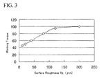
- the results of the measurement are shown in Table 3 and Figure 3 .
- the values of working torque shown in Table 3 and Figure 3 are expressed by an index where the value of test member 10 with surface roughness Rz of 200 ⁇ m is 100. [Table 3] Surface Rroughness Rz ( ⁇ m) Working torque 200 100 120 95 80 80 40 60 20 50 10 45
- the working torque decreased with the decrease of the surface roughness Rz. Particularly, the working torque remarkably began to decrease when the Rz approached at approximately 100 ⁇ m. From the results, it is concluded that the preferable surface roughness of the respective sliding surfaces in both of the valve stem and the valve bush is 100 ⁇ m or less in units of Rz.
Landscapes
- Engineering & Computer Science (AREA)
- General Engineering & Computer Science (AREA)
- Mechanical Engineering (AREA)
- Lift Valve (AREA)
- Control Of Turbines (AREA)
Abstract
Description
- The present invention relates to a valve gear and, in particular, to a valve gear capable of preventing the sticking between the valve stem of a steam valve and a valve bush supporting the valve stem.
- A main steam valve in a steam turbine is used under harsh conditions of high temperature and high pressure, and further takes a task of controlling high-speed steam flow. Under high temperature, the surface of a metal is in an activated state to react with the high-temperature steam present in the atmosphere to produce an oxide film. This oxide film has different adhesion strength to the base metal, depending on the composition of the base metal and the atmospheric conditions, and undergoes delamination at every repeated opening-closing movement of the valve. The delaminated matter is deposited locally in the recessed portions of the valve stem by the sliding of the valve stem so as to fill in the clearance between the valve bush and the valve stem. Consequently, the sticking of the valve stem is caused as the case may be. Accordingly, at the time of the periodic inspection of a steam turbine, it is necessary to conduct maintenance work for removing the oxide film by disassembling the members surrounding the valve stem. Additionally, the generation amount of the deposition substance is anticipated, and accordingly the clearance between the valve stem and the valve bush is set at a sufficiently large value. Therefore, the steam amount leaking from the portion surrounding the valve stem is increased to cause problems such as the decrease of the thermal efficiency of a whole plant.
- A proposal for solving the problem of such the sticking is disclosed in Patent Document 1. Patent Document 1 proposes that the main body of a valve stem and a bush (hereinafter referred to as a valve bush) be formed from materials having almost the same linear expansion coefficient, that a Ni alloy be building-up welded on the outer surface of a sliding part of the valve stem, and that the building-up welded Ni alloy portion be subjected to a nitriding treatment.
- According to the proposal of Patent Document 1, because a Ni alloy is provided on the outer surface of a sliding part of the valve stem, little oxide film is generated and hence the occurrence of sticking can be prevented. Furthermore, because the main body of the valve stem and the valve bush are formed from materials having almost the same linear expansion coefficient, it is possible to ensure the clearance between sliding parts formed between the two even when the valve is used at high temperatures.
- Although Patent Document 1 describes that austenite stainless steels, 12% Cr-based stainless steels and low-alloy steels (Cr-Mo(-V) steels) are used in the main body of the valve stem and the valve bush, there is no specific description related to Ni alloys.
- Patent Document 1: Japanese Patent Publication No.
1-28269 - According to the proposal of Patent Document 1, particularly, in the building-up welding of a Ni alloy, the Ni alloy is provided only in necessary areas. Therefore, this is an effective technique because it is unnecessary to work the Ni alloy, which is a difficult-to-machine material. However, from the standpoint of corrosion due to a potential difference, it is undesirable to use different metals in a high-temperature corrosive environment. It has been empirically clear that corrosion becomes apt to occur when a load gives a microdisplacement to a member and this displacement reaches a level that exceeds an allowable range. Therefore, it is undesirable to use building-up welding in a portion to which such a load is applied. In particular, because the valve stem undergoes microvibrations due to steam flow and a load is given to the valve bush that receives the vibrations, it is advisable to avoid the use of building-up welding in a valve gear that controls the vapor flow.
- The present invention was achieved on the basis of such technical problems and has as its object to provide a valve gear in which corrosion due to a potential difference does not occur and which can reduce the corrosion occurrence even when loads due to microvibrations are given.
- For the purpose of achieving such an object as described above, the present inventors conceived the idea that the corrosion due to a potential difference is prevented by forming the whole of a valve stem and a valve bush from a Ni-based superalloy and the corrosion occurrence is reduced by forming the valve bush from a cast part that easily absorbs microvibrations. That is, the valve gear of the present invention comprises a valve stem and a valve bush that slidably supports the valve stem, and is characterized in that the valve stem is formed from a forged part made of a Ni-based superalloy, and that the valve bush is formed from a cast part made of a Ni-based superalloy.
- In the valve gear of the present invention, it is preferred that the surface roughness of a sliding surface of the valve stem in contact with the valve bush and the surface roughness of a sliding surface of the valve bush in contact with the valve stem be 100 µm or less in units of Rz.
- As described above, according to the present invention, it is possible to prevent the occurrence of sticking and corrosion due to a potential difference by forming the whole of both of a valve stem and a valve bush from a Ni-based superalloy. Furthermore, it is possible to reduce the corrosion occurrence by forming the valve bush from a cast part that easily absorbs microvibrations.
-
-
Figure 1 is a cross-sectional view showing the construction of a steam valve in this embodiment; -
Figure 2 is a cross-sectional view showing the construction of a test member used in an example; and -
Figure 3 is a graph showing the relationship between surface roughness Rz and working torque in the example. -
- 1 ... Valve disc casing, 2a, 2b ... Steam inlet, 3 ... Steam outlet, 4 ... Valve seat, 5 ... Valve disc, 6 ... Valve stem, 7 ... Valve bush, 8 ... Bonnet, 10 ... Test member, 11 ... Simulated valve stem, 12 ... Simulated valve bush
- Hereinafter, the present invention is described in detail with reference to the accompanying drawings.
-
Figure 1 is a cross-sectional view showing an example of the construction of a valve gear (high-temperature steam valve, Patent Document 2) to which the present invention is applied. InFigure 1 , a valve disc casing 1 hassteam inlets valve disc 5 is attached so as to be able to approach or depart from this valve seat 4, and the shutoff and outflow of steam is performed by the movement of thevalve disc 5. Thevalve stem 6 is such that one end thereof is connected to a middle portion of a lower end of thevalve disc 5 and the other end thereof extends through an internal space confined by a peripheral wall of thevalve disc 5, and slidably pierces through the interior of an elongated, cylindrical valve bush 7 so as to be supported. This valve bush 7 pierces through a middle portion of abonnet 8 attached to an upper opening of the valve disc casing 1, and is supported by thisbonnet 8. Thebonnet 8 integrally has acylindrical portion 9 that extends downward and opens, and thevalve disc 5 is slidably inserted into thiscylindrical portion 9. - Patent Document 2: Japanese Patent Laid-Open
6-101769 - When the steam valve having the above-described construction is in a fully closed condition, a forward end face of the
valve disc 5 contacts the valve seat 4 and the flow of steam that enters the interior of the valve disc casing 1 from thesteam inlets valve disc 5 and the valve seat 4. Therefore, the steam does not flow trough the steam outlet 3. Upward moving thevalve disc 5 by use of thevalve stem 6 brings the steam valve into an open condition, and the steam passes through a clearance formed between thevalve disc 5 and the valve seat 4 and is discharged from the steam outlet 3. Thevalve stem 6 is actuated via an actuator (not shown) and a mechanical element that transmits the output of the actuator to thevalve stem 6. - Although the steam valve shown in
Figure 1 was described here by way of example, it is needless to say that a valve gear to which the present invention is applied is not limited to the embodiment shown inFigure 1 . - The
valve stem 6 and the valve bush 7 in this embodiment are made of a Ni-based superalloy. Representative materials for Ni-based superalloys are shown in Table 1 (JIS G4901). All of the materials contain Ni as a main constituent element and further contain Cr in the range of 14 to 25 wt%. Although in this embodiment all of the Ni-based superalloys shown in Table 1 may be used, among others NCF718 is preferable to use.[Table 1] C Si Mn P S Ni Cr Fe Mo Cu Al Ti Nb+Ta B NCF600 0.15 and under 0.50 and under 1.00 and under 0.030 and under 0.015 and under 72.00 and over 14.00-17.00 6.00- 10.00 - 0.50 and under - - - - NCF601 0.10 0 nd under 0.50 and under 1.00 and under 0.030 and under 0.015 and under 58.00- 63.00 21.00-25.00 bal. - 1.00 and under 1.00-1.70 - - - NCF625 0.010 and under 0.50 and under 0.50 and under 0.015 and under 0.015 and under 58.00 andover 20.00-23.00 5.00 and under 8.00-10.00 - 0.40 and under 0.40 and under 3.15-4.15 - NCF690 0.05 and under 0.50 and under 0.50 and under 0.030 and under 0.015 and under 58.00 and over 27.00- 31.00 7.00-11.00 - 0.50 and under - - - - NCF718 0.08 and under 0.35 and under 0.35 and under 0.015 and under 0.015 and under 50.00- 55.00 17.00-21.00 bal. 2.80-3.30 0.30 and under 0.20-0.80 0.65-1.15 4.75-5.50 0.006 and under NCF750 0.08 and under 0.50 and under 1.00 and under 0.030 and under 0.015 and under 70.00 and over 14.00-17.00 5.00- 9.00 - 0.50 and under 0.40-1.00 2.25-2.75 0.70-1.20 - NCF751 0.10 and under 0.50 and under 1.00 and under 0.030 and under 0.015 and under 70.00 and over 14.00-17.00 5.00- 9.00 - 0.50 and under 0.90-1.50 2.00-2.60 0.70-1.20 - NCF800 0.10 and under 1.00 and under 1.50 and under 0.030 and under 0.015 and under 30.00- 35.00 19.00-23.00 bal. - 0.75 and under 0.15-0.60 0.15-0.60 - - NCF800H 0.05-0.10 1.00 and under 1.50 and under 0.030 and under 0.015 and under 30.00- 35.00 19.00-23.00 bal. - 0.75 and under 0.15-0.60 0.15-0.60 - - NCF825 0.05 and under 0.50 and under 1.00 and under 0.030 and under 0.015 and under 38.00- 46.00 19.50-23.50 bal. 2.50-3.50 1.50-3.00 0.20 and under 0.60-1.20 - - NCF80A 0.04-0.10 1.00 and under 1.00 and under 0.030 and under 0.015 and under bal. 18.00-21.00 1.50 and under - 0.20 and under 1.00-1.80 1.80-2.70 - - - The
valve stem 6 and the valve bush 7 are both made of a Ni-based superalloy and this means that thewhole valve stem 6 and the whole valve bush 7 are made of a Ni-based superalloy. Therefore, the present invention excludes an embodiment such that the base metal is made of low-alloy steels (Cr-Mo(-V) steels), 12 Cr-based stainless steels, austenite stainless steels or the like, and the building-up welding of a Ni-based superalloy is partly provided with the base metal. This is because forming thevalve stem 6 or the valve bush 7 from different materials causes corrosion due to a potential difference to occur. From this point of view, it is preferred that thevalve stem 6 and the valve bush 7 be made of a Ni-based superalloy of the same kind. For example, both of thevalve stem 6 and the valve bush 7 are preferably made of NCF718 among the Ni-based superalloys shown in Table 1. - Next, the
valve stem 6 is formed from a forged part and the valve bush 7 is formed from a cast part. A forged part and a cast part differ in some mechanical properties even if they are made of the same Ni-based superalloy. That is, in terms of mechanical strength, a forged part is superior to a cast part. In terms of vibration damping performance, a cast part is superior to a forged part. - When comparing the
valve stem 6 with the valve bush 7, thevalve stem 6 actuated by an actuator is required to have higher mechanical strength. Hence the present invention forms the valve stem 6 from a forged part having higher mechanical strength. - As described above, microvibrations occur in the
valve stem 6 due to steam flow and loads are given to the valve bush 7 that receives the microvibrations. Thereby corrosion becomes apt to occur in the valve bush 7. Therefore, the present invention forms the valve bush 7 from a cast part having a higher capability of damping the vibrations received from thevalve stem 6. As described above, although a cast part is inferior to a forged part in mechanical strength, the level of mechanical strength required for the valve bush 7 is low compared with that of thevalve stem 6 and hence the valve bush 7 can have sufficient endurance even when formed from a cast part. - The
valve stem 6 and the valve bush 7 may be produced according to a general manufacturing method of Ni-based superalloy members. The valve stem 6 formed from a forged part may be obtained by preparing an ingot from a molten alloy with a prescribed composition, forging and rolling this ingot and then performing prescribed heat treatment. The valve bush 7 formed from a cast part may be obtained by filling a molten alloy with a prescribed composition into a mold having a prescribed shaped cavity, cooling the molten alloy and then performing prescribed heat treatment. Of course, in order to obtain thevalve stem 6 and valve bush 7 having prescribed shapes, appropriate machining, such as cutting and polishing, may be performed. - In the
valve stem 6 and the valve bush 7, the preferable surface roughness Rz (JIS B0601) of the respective sliding surfaces is 100 µm or less. This is because reducing the surface roughness of the sliding surfaces in thevalve stem 6 and the valve bush 7 leads to a decrease in the working torque of thevalve stem 6. The surface roughness Rz of the respective sliding surfaces is preferably 100 µm or less, more preferably 50 µm or less, and particularly preferably on the order of 10 µm. Reducing the working torque of thevalve stem 6 enables a downsizing of the actuator that actuates thevalve stem 6 and also enables the precise control of the valve opening. - The
valve stem 6 and the valve bush 7 may be subjected to a surface treatment, such as nitriding treatment, carburizing treatment and carbonitriding treatment. Such the surface treatment improves the hardness of the sliding surfaces in thevalve stem 6 and the valve bush 7 and enables the abrasion amount to be reduced. For example, nitriding treatment may be performed as follows. When ammonium gas (NH3) is heated to 500 to 520°C, part of the gas is separated into nitrogen (N) and hydrogen (H), and the nitrogen combines with elements in a member to be nitrided to form hard nitrides. Examples of elements that combine with nitrogen include titanium (Ti), aluminum (Al), chromium (Cr) and molybdenum (Mo) and, as shown in Table 1, many Ni-based superalloys contain these elements. - In the carburizing treatment, the carbon content of a surface layer of a member is increased and only the surface layer is quenched and hardened. In the carbonitriding treatment, carbon and nitrogen are caused to simultaneously infiltrate into a surface of a member at temperatures of 800°C or higher.
- Although both of the
valve stem 6 and the valve bush 7 are made of a Ni-based superalloy in the present embodiment, the friction coefficient(dry friction) of Ni-based alloys used in contact relation is on the order of 0.50. In this connection, although thevalve stem 6 and the valve bush 7 can be made of a Co-based superalloy capable of preventing the generation of an oxide film (for example, Stellite (registered trade name of Deloro Stellite Company), the working torque of thevalve stem 6 increases because the friction coefficient of Co-based alloys used in contact relation is as high as 0.56. Also, Co-based superalloys are difficult-to-machine materials compared with Ni-based superalloys. Furthermore, Co-based superalloys have the drawback that the cost of Co, which is a main constituent element of Co-based superalloys, is higher than that of Ni, and with the wild ups and downs. Also from the above-described viewpoints, Ni-based superalloys are preferable to use among several superalloys. - In the steam valve of this embodiment, any material may be used for portions except the
valve stem 6 and the valve bush 7. The portions except thevalve stem 6 and the valve bush 7 may be made of a Ni-based superalloy as in thevalve stem 6 and the valve bush 7 and may be made of low-alloy steels (Cr-Mo(-V) steels), 12 Cr-based stainless steels, austenite stainless steels or the like. - A
test member 10 shown inFigure 2 was prepared. A high-temperature corrosion test was conducted by subjecting thistest member 10 to an environment in which high-temperature steam (approximately 593°C) flows. Thistest member 10 is composed of a simulated valve stem 11 corresponding to thevalve stem 6 shown inFigure 1 and asimulated valve bush 12 corresponding to the valve bush 7 shown inFigure 1 . Incidentally, inFigure 2 , φa = 20 mm, L1 = 90 mm, L2 = 100 mm. The clearance between the outer diameter of thesimulated valve stem 11 and thesimulated valve bush 12 was set at 0.02 mm. - The following four
test members 10 were prepared by changing materials for thesimulated valve stem 11 and thesimulated valve bush 12. - No. 1 Simulated valve stem 11: a forged part made of NCF718 (the composition of NCF718 is shown below; ditto for the following)
Simulated valve bush 12: a cast part made of NCF718 - No. 2 Simulated valve stem 11: a forged part made of NCF718
Simulated valve bush 12: a forged part made of NCF718 - No. 3 Simulated valve stem 11: a forged part made of SCM435 (the composition of SCM435 is shown below; ditto for the following)
Simulated valve bush 12: a forged part made of SCM435 - No. 4 Simulated valve stem 11: NCF718 is building-up welded on a sliding surface of a forged part made of SCM435
Simulated valve bush 12: NCF718 is building-up welded on a sliding surface of a forged part made of SCM435
NCF718: 52 wt% Ni-18 wt% Cr-3 wt% Mo-5 wt% Nb-0.8 wt% Ti-0.5 wt% Al-Bal.Fe - SCM435: 1.05 wt% Cr-0.22 wt% Mo-0.35 wt% C-0.25 wt% Si-0.72 wt% Mn-not more than 0.03 wt% P-not more than 0.03 wt% S-not more than 0.03 wt% Cu-Bal.Fe
- Because residual stress affects corrosion, residual stress was relieved in each of the members by performing heat treatment suited to the machining of each of the members.
- The powder building-up welding of NCF718 was performed by plasma powder building-up welding and a building-up welded layer having a thickness of 1.5 mm was formed.
- An outer peripheral surface (a sliding surface) of the
simulated valve stem 11 and an inner circumferential surface (a sliding surface) of thesimulated valve bush 12 were each polished so that the surface roughness of the surfaces became 200 µm in units of Rz. - In the high-temperature corrosion test, each of the above-described
test members 10 was exposed for 36 months to an environment in which high-temperature steam (approximately 593°C) flows. On that occasion, at intervals of six hours, thesimulated valve stem 11 was caused to reciprocate in its length direction relative to thesimulated valve bush 12. The stroke of this reciprocation is 50 mm. After the high-temperature corrosion test, thesimulated valve stem 11 was rotated, with thesimulated valve bush 12 kept in a fixed condition, and the torque necessary for the rotation (working torque) was measured. After the measurement of the working torque, thesimulated valve stem 11 was extracted from thesimulated valve bush 12, and the abrasion amount of the surface of thesimulated valve stem 11 was measured. The results of the measurement are shown in Table 2. The working torque and the abrasion amount are both expressed by an index where each of the values for No. 3 is 100.[Table 2] No. Simulated Valve Stem 11Simulated Valve Bush 12Working Torque Abrasion Amount Material Process Material Process 1 NCF718 Forging NCF718 Casting 80 80 2 NCF718 Forging NCF718 Forging 80 95 3 SCM435 Forging SCM435 Forging 100 100 4 SCM435 with building-up welding of NCF718 Forging (SCM435) SCM435 with building-up welding of NCF718 Forging (SCM435) 80 150 - As shown in Table 2, No. 2 had a larger abrasion amount compared with No. 1 although the working torque of No. 2 was small. In No. 2 as a
test member 10, thesimulated valve bush 12 was formed from a forged part, thus it was susceptible to the affect of loads caused by vibrations of thesimulated valve stem 11 due to the flow of high-temperature steam. - No. 3 had a large working torque because an oxide film was generated between the
simulated valve stem 11 and thesimulated valve bush 12. In No. 3, thesimulated valve bush 12 was formed from a forged part, thus the abrasion amount was affected and increased by the loads caused by vibrations of thesimulated valve stem 11 due to the flow of high-temperature steam. - No. 4 was provided with a building-up welded layer of NCF718 on the surface although the base metal was SCM435 and therefore, it was possible to prevent an oxide film from being generated in a contact area between the
simulated valve stem 11 and thesimulated valve bush 12. Thereby the working torque was reduced. However, because thesimulated valve stem 11 andsimulated valve bush 12 are each made of different materials, corrosion due to a potential difference occurred and the abrasion amount was large. - In contrast to the forgoing, No. 1 according to the present invention had a small working torque because the
simulated valve stem 11 and thesimulated valve bush 12 were both made of NCF718, which was a Ni-based superalloy in which the generation of an oxide film scarcely occurred. Furthermore, in No. 1, both of thesimulated valve stem 11 and thesimulated valve bush 12 were made of NCF718 and integrally formed. Therefore, No. 1 was not affected by corrosion due to a potential difference and the abrasion amount was also small. - Next,
test members 10 similar to No. 1 shown in Table 2 were prepared with the exception that the surface roughness of the respective sliding surfaces of thesimulated valve stem 11 and thesimulated valve bush 12 was changed as shown in Table 3. A high-temperature corrosion test was conducted on thesetest members 10 as in the same manner described above and thereafter the working torque was measured for the test members. The results of the measurement are shown in Table 3 andFigure 3 . The values of working torque shown in Table 3 andFigure 3 are expressed by an index where the value oftest member 10 with surface roughness Rz of 200 µm is 100.[Table 3] Surface Rroughness Rz (µm) Working torque 200 100 120 95 80 80 40 60 20 50 10 45 - As shown in Table 3 and
Figure 3 , the working torque decreased with the decrease of the surface roughness Rz. Particularly, the working torque remarkably began to decrease when the Rz approached at approximately 100 µm. From the results, it is concluded that the preferable surface roughness of the respective sliding surfaces in both of the valve stem and the valve bush is 100 µm or less in units of Rz.
Claims (2)
- A valve gear comprising a valve stem and a valve bush that slidably supports the valve stem, wherein the valve stem is formed from a forged part made of a Ni-based superalloy, and the valve bush is formed from a cast part made of a Ni-based superalloy.
- The valve gear according to claim 1, wherein the surface roughness of a sliding surface of the valve stem in contact with the valve bush and the surface roughness of a sliding surface of the valve bush in contact with the valve stem are 100 µm or less in units of Rz.
Applications Claiming Priority (2)
| Application Number | Priority Date | Filing Date | Title |
|---|---|---|---|
| JP2007122111A JP2008275119A (en) | 2007-05-07 | 2007-05-07 | Valve device |
| PCT/JP2008/058342 WO2008139950A1 (en) | 2007-05-07 | 2008-05-01 | Valve device |
Publications (3)
| Publication Number | Publication Date |
|---|---|
| EP2146121A1 true EP2146121A1 (en) | 2010-01-20 |
| EP2146121A4 EP2146121A4 (en) | 2013-11-27 |
| EP2146121B1 EP2146121B1 (en) | 2016-12-21 |
Family
ID=40002158
Family Applications (1)
| Application Number | Title | Priority Date | Filing Date |
|---|---|---|---|
| EP08752272.8A Active EP2146121B1 (en) | 2007-05-07 | 2008-05-01 | Valve device |
Country Status (6)
| Country | Link |
|---|---|
| US (1) | US8235357B2 (en) |
| EP (1) | EP2146121B1 (en) |
| JP (1) | JP2008275119A (en) |
| KR (1) | KR101157706B1 (en) |
| CN (1) | CN101548120B (en) |
| WO (1) | WO2008139950A1 (en) |
Cited By (1)
| Publication number | Priority date | Publication date | Assignee | Title |
|---|---|---|---|---|
| FR3087685A1 (en) * | 2018-10-31 | 2020-05-01 | Centre Technique Des Industries Mecaniques | METHOD OF MANUFACTURING A SEALING ASSEMBLY FOR CONTROLLING THE FLOW OF FLUID FLOWS |
Families Citing this family (9)
| Publication number | Priority date | Publication date | Assignee | Title |
|---|---|---|---|---|
| WO2012105109A1 (en) * | 2011-02-02 | 2012-08-09 | シーケーディ株式会社 | Vacuum control valve, vacuum control apparatus, and computer program |
| ITMI20110830A1 (en) * | 2011-05-12 | 2012-11-13 | Alstom Technology Ltd | VALVE FOR ONE STEAM TURBINE 700 C |
| JP5993191B2 (en) | 2012-04-23 | 2016-09-14 | Ckd株式会社 | Linear actuator, vacuum control device and computer program |
| CN102974771A (en) * | 2012-11-13 | 2013-03-20 | 安徽春辉仪表线缆集团有限公司 | Casting forming preparation method of pressure reducing valve body |
| CN105840849A (en) * | 2016-04-26 | 2016-08-10 | 邵阳富鑫实业有限公司 | Automatic control valve for molten aluminum pipelining |
| CN105952961B (en) * | 2016-06-08 | 2019-06-14 | 贾广生 | Gathering and transporting split control valve |
| DE102018102251A1 (en) * | 2018-02-01 | 2019-08-01 | Samson Aktiengesellschaft | Valve body modular system and lift valve |
| WO2020122938A1 (en) | 2018-12-14 | 2020-06-18 | Halliburton Energy Services, Inc. | Pump valve guide for hydraulic fracturing |
| JP2025087971A (en) * | 2023-11-30 | 2025-06-11 | 株式会社東芝 | Steam valve and steam turbine plant equipped with same |
Family Cites Families (22)
| Publication number | Priority date | Publication date | Assignee | Title |
|---|---|---|---|---|
| US2339384A (en) * | 1940-12-12 | 1944-01-18 | Westinghouse Air Brake Co | Compressor governor |
| US2786487A (en) * | 1951-11-08 | 1957-03-26 | Spence Paulsen | Double-seated valve |
| US2622617A (en) * | 1952-04-10 | 1952-12-23 | Gen Electric | Valve for controlling marine steam turbines |
| JPS58174765A (en) * | 1982-04-05 | 1983-10-13 | Hitachi Ltd | steam valve |
| CA1229330A (en) | 1982-09-10 | 1987-11-17 | James E. Barker | Unitary bearing means for butterfly valves |
| US4589628A (en) | 1982-09-10 | 1986-05-20 | General Signal Corporation | Unitary bearing and locator assembly for rotatable valves |
| JPS6428269A (en) | 1987-07-24 | 1989-01-30 | Nec Corp | Oxide superconducting composition |
| JP2947640B2 (en) * | 1991-06-21 | 1999-09-13 | 日本ピストンリング株式会社 | Synchronizer ring |
| JP2941544B2 (en) | 1992-01-09 | 1999-08-25 | 三菱重工業株式会社 | High temperature steam valve |
| DE69311302T2 (en) * | 1993-03-26 | 1998-01-08 | Fuji Valve | Process for the surface treatment of a fan tappet |
| JPH07127402A (en) * | 1993-10-29 | 1995-05-16 | Sumitomo Electric Ind Ltd | Combination of adjusting shim and cam |
| US5517956A (en) * | 1994-08-11 | 1996-05-21 | Del West Engineering, Inc. | Titanium engine valve |
| IN189877B (en) * | 1997-08-04 | 2003-05-03 | Luk Lamellen & Kupplungsbau | |
| US6250604B1 (en) * | 1998-03-02 | 2001-06-26 | T & R Solutions, Inc. | Valve stem and method of manufacturing, improved stem packing |
| WO2000037695A1 (en) * | 1998-12-23 | 2000-06-29 | United Technologies Corporation | Die cast superalloy articles |
| US6793198B2 (en) * | 1999-02-22 | 2004-09-21 | Caldera Engineering, Llc | Banded valve plug head |
| JP3781402B2 (en) * | 1999-03-03 | 2006-05-31 | 三菱重工業株式会社 | Low thermal expansion Ni-base superalloy |
| JP2004003599A (en) * | 2002-03-29 | 2004-01-08 | Denso Corp | Electromagnetic drive |
| JP4220186B2 (en) | 2002-06-20 | 2009-02-04 | 株式会社東芝 | Valve device and manufacturing method thereof |
| JP2005321061A (en) | 2004-05-11 | 2005-11-17 | Kubota Corp | High temperature valve |
| JP4372712B2 (en) * | 2005-03-30 | 2009-11-25 | 本田技研工業株式会社 | Titanium alloy valve lifter and manufacturing method thereof |
| JP2007057055A (en) | 2005-08-26 | 2007-03-08 | Inter-Valve Technologies Corp | Valve device |
-
2007
- 2007-05-07 JP JP2007122111A patent/JP2008275119A/en not_active Withdrawn
-
2008
- 2008-05-01 EP EP08752272.8A patent/EP2146121B1/en active Active
- 2008-05-01 CN CN2008800008260A patent/CN101548120B/en active Active
- 2008-05-01 US US12/311,427 patent/US8235357B2/en active Active
- 2008-05-01 KR KR1020097006291A patent/KR101157706B1/en active Active
- 2008-05-01 WO PCT/JP2008/058342 patent/WO2008139950A1/en not_active Ceased
Cited By (1)
| Publication number | Priority date | Publication date | Assignee | Title |
|---|---|---|---|---|
| FR3087685A1 (en) * | 2018-10-31 | 2020-05-01 | Centre Technique Des Industries Mecaniques | METHOD OF MANUFACTURING A SEALING ASSEMBLY FOR CONTROLLING THE FLOW OF FLUID FLOWS |
Also Published As
| Publication number | Publication date |
|---|---|
| US8235357B2 (en) | 2012-08-07 |
| CN101548120B (en) | 2011-06-22 |
| EP2146121B1 (en) | 2016-12-21 |
| CN101548120A (en) | 2009-09-30 |
| JP2008275119A (en) | 2008-11-13 |
| KR20090096409A (en) | 2009-09-10 |
| US20100032607A1 (en) | 2010-02-11 |
| KR101157706B1 (en) | 2012-06-20 |
| EP2146121A4 (en) | 2013-11-27 |
| WO2008139950A1 (en) | 2008-11-20 |
Similar Documents
| Publication | Publication Date | Title |
|---|---|---|
| EP2146121B1 (en) | Valve device | |
| EP1193316B1 (en) | Nuclear power plant comprising valves made of corrosion resisting and wear resisting alloy | |
| EP3444452B1 (en) | High performance iron-based alloys for engine valvetrain applications and methods of making and use thereof | |
| US7754143B2 (en) | Cobalt-rich wear resistant alloy and method of making and use thereof | |
| EP2933445B1 (en) | An exhaust valve for an internal combustion engine, and a method of strengthening an annular valve seat area in an exhaust valve | |
| EP1614762B1 (en) | Wear resistant alloy for valve seat insert | |
| US8430075B2 (en) | Superaustenitic stainless steel and method of making and use thereof | |
| JP2012507636A (en) | Method of manufacturing a composite product having a surface area of an abrasion resistant coating, such product, and the use of steel to obtain the coating | |
| US4829950A (en) | Valve lifter and method of producing the same | |
| CN101970811B (en) | Movable wall component in the form of an exhaust valve stem or piston for an internal combustion engine and method for producing such a component | |
| US10094010B2 (en) | Cobalt-free, galling and wear resistant austenitic stainless steel hard-facing alloy | |
| EP2147737A1 (en) | Valve gear | |
| EP3915717A1 (en) | Ni-based alloy, and ni-based alloy product and methods for producing the same | |
| US8919316B2 (en) | Valve system for controlling the charge exchange | |
| EP2318668B1 (en) | Cylinder head with valve seat and method for the production thereof | |
| EP3578688A1 (en) | Sliding member, and sliding member of internal combustion engine | |
| US20030044637A1 (en) | Liquid phase diffusion welded metal-made precision machine component and production method thereof | |
| US20070193658A1 (en) | Steel For Mechanical Parts, Method For Producing Mechanical Parts From Said Steel And The Thus Obtainable Mechanical Parts | |
| JP2004183051A (en) | Valve stem, manufacturing method thereof, and steam valve using the same | |
| JP5632358B2 (en) | Welding material for hardfacing and machine parts with overlay welded layers thereby | |
| EP1876255B1 (en) | Carbonitriding or cementation steel and method of producing parts with said steel | |
| US20250257435A1 (en) | MOLYBDENUM-Based Alloy | |
| JP3721300B2 (en) | valve | |
| HK1152350B (en) | Cobalt-rich wear resistant alloy and method of making and use thereof |
Legal Events
| Date | Code | Title | Description |
|---|---|---|---|
| PUAI | Public reference made under article 153(3) epc to a published international application that has entered the european phase |
Free format text: ORIGINAL CODE: 0009012 |
|
| 17P | Request for examination filed |
Effective date: 20090330 |
|
| AK | Designated contracting states |
Kind code of ref document: A1 Designated state(s): AT BE BG CH CY CZ DE DK EE ES FI FR GB GR HR HU IE IS IT LI LT LU LV MC MT NL NO PL PT RO SE SI SK TR |
|
| AX | Request for extension of the european patent |
Extension state: AL BA MK RS |
|
| RBV | Designated contracting states (corrected) |
Designated state(s): AT BE BG CH CY CZ DE DK EE ES FI FR GB GR HR HU IE IS IT LI LT LU LV MC MT NL NO PL PT RO SE SI SK TR |
|
| DAX | Request for extension of the european patent (deleted) | ||
| A4 | Supplementary search report drawn up and despatched |
Effective date: 20131028 |
|
| RIC1 | Information provided on ipc code assigned before grant |
Ipc: F16K 1/32 20060101AFI20131022BHEP Ipc: F16K 27/02 20060101ALI20131022BHEP |
|
| 17Q | First examination report despatched |
Effective date: 20140703 |
|
| RAP1 | Party data changed (applicant data changed or rights of an application transferred) |
Owner name: MITSUBISHI HITACHI POWER SYSTEMS, LTD. |
|
| GRAP | Despatch of communication of intention to grant a patent |
Free format text: ORIGINAL CODE: EPIDOSNIGR1 |
|
| INTG | Intention to grant announced |
Effective date: 20160711 |
|
| GRAS | Grant fee paid |
Free format text: ORIGINAL CODE: EPIDOSNIGR3 |
|
| GRAA | (expected) grant |
Free format text: ORIGINAL CODE: 0009210 |
|
| AK | Designated contracting states |
Kind code of ref document: B1 Designated state(s): AT BE BG CH CY CZ DE DK EE ES FI FR GB GR HR HU IE IS IT LI LT LU LV MC MT NL NO PL PT RO SE SI SK TR |
|
| REG | Reference to a national code |
Ref country code: GB Ref legal event code: FG4D |
|
| REG | Reference to a national code |
Ref country code: CH Ref legal event code: EP |
|
| REG | Reference to a national code |
Ref country code: IE Ref legal event code: FG4D |
|
| REG | Reference to a national code |
Ref country code: AT Ref legal event code: REF Ref document number: 855804 Country of ref document: AT Kind code of ref document: T Effective date: 20170115 |
|
| REG | Reference to a national code |
Ref country code: DE Ref legal event code: R096 Ref document number: 602008047999 Country of ref document: DE |
|
| PG25 | Lapsed in a contracting state [announced via postgrant information from national office to epo] |
Ref country code: LV Free format text: LAPSE BECAUSE OF FAILURE TO SUBMIT A TRANSLATION OF THE DESCRIPTION OR TO PAY THE FEE WITHIN THE PRESCRIBED TIME-LIMIT Effective date: 20161221 |
|
| REG | Reference to a national code |
Ref country code: DE Ref legal event code: R082 Ref document number: 602008047999 Country of ref document: DE Representative=s name: VOSSIUS & PARTNER PATENTANWAELTE RECHTSANWAELT, DE |
|
| REG | Reference to a national code |
Ref country code: LT Ref legal event code: MG4D |
|
| REG | Reference to a national code |
Ref country code: NL Ref legal event code: MP Effective date: 20161221 |
|
| PG25 | Lapsed in a contracting state [announced via postgrant information from national office to epo] |
Ref country code: NO Free format text: LAPSE BECAUSE OF FAILURE TO SUBMIT A TRANSLATION OF THE DESCRIPTION OR TO PAY THE FEE WITHIN THE PRESCRIBED TIME-LIMIT Effective date: 20170321 Ref country code: SE Free format text: LAPSE BECAUSE OF FAILURE TO SUBMIT A TRANSLATION OF THE DESCRIPTION OR TO PAY THE FEE WITHIN THE PRESCRIBED TIME-LIMIT Effective date: 20161221 Ref country code: GR Free format text: LAPSE BECAUSE OF FAILURE TO SUBMIT A TRANSLATION OF THE DESCRIPTION OR TO PAY THE FEE WITHIN THE PRESCRIBED TIME-LIMIT Effective date: 20170322 Ref country code: LT Free format text: LAPSE BECAUSE OF FAILURE TO SUBMIT A TRANSLATION OF THE DESCRIPTION OR TO PAY THE FEE WITHIN THE PRESCRIBED TIME-LIMIT Effective date: 20161221 |
|
| REG | Reference to a national code |
Ref country code: AT Ref legal event code: MK05 Ref document number: 855804 Country of ref document: AT Kind code of ref document: T Effective date: 20161221 |
|
| PG25 | Lapsed in a contracting state [announced via postgrant information from national office to epo] |
Ref country code: FI Free format text: LAPSE BECAUSE OF FAILURE TO SUBMIT A TRANSLATION OF THE DESCRIPTION OR TO PAY THE FEE WITHIN THE PRESCRIBED TIME-LIMIT Effective date: 20161221 Ref country code: HR Free format text: LAPSE BECAUSE OF FAILURE TO SUBMIT A TRANSLATION OF THE DESCRIPTION OR TO PAY THE FEE WITHIN THE PRESCRIBED TIME-LIMIT Effective date: 20161221 |
|
| PG25 | Lapsed in a contracting state [announced via postgrant information from national office to epo] |
Ref country code: NL Free format text: LAPSE BECAUSE OF FAILURE TO SUBMIT A TRANSLATION OF THE DESCRIPTION OR TO PAY THE FEE WITHIN THE PRESCRIBED TIME-LIMIT Effective date: 20161221 |
|
| PG25 | Lapsed in a contracting state [announced via postgrant information from national office to epo] |
Ref country code: SK Free format text: LAPSE BECAUSE OF FAILURE TO SUBMIT A TRANSLATION OF THE DESCRIPTION OR TO PAY THE FEE WITHIN THE PRESCRIBED TIME-LIMIT Effective date: 20161221 Ref country code: RO Free format text: LAPSE BECAUSE OF FAILURE TO SUBMIT A TRANSLATION OF THE DESCRIPTION OR TO PAY THE FEE WITHIN THE PRESCRIBED TIME-LIMIT Effective date: 20161221 Ref country code: IS Free format text: LAPSE BECAUSE OF FAILURE TO SUBMIT A TRANSLATION OF THE DESCRIPTION OR TO PAY THE FEE WITHIN THE PRESCRIBED TIME-LIMIT Effective date: 20170421 Ref country code: CZ Free format text: LAPSE BECAUSE OF FAILURE TO SUBMIT A TRANSLATION OF THE DESCRIPTION OR TO PAY THE FEE WITHIN THE PRESCRIBED TIME-LIMIT Effective date: 20161221 Ref country code: EE Free format text: LAPSE BECAUSE OF FAILURE TO SUBMIT A TRANSLATION OF THE DESCRIPTION OR TO PAY THE FEE WITHIN THE PRESCRIBED TIME-LIMIT Effective date: 20161221 |
|
| PG25 | Lapsed in a contracting state [announced via postgrant information from national office to epo] |
Ref country code: LU Free format text: LAPSE BECAUSE OF NON-PAYMENT OF DUE FEES Effective date: 20170531 Ref country code: IT Free format text: LAPSE BECAUSE OF FAILURE TO SUBMIT A TRANSLATION OF THE DESCRIPTION OR TO PAY THE FEE WITHIN THE PRESCRIBED TIME-LIMIT Effective date: 20161221 Ref country code: PL Free format text: LAPSE BECAUSE OF FAILURE TO SUBMIT A TRANSLATION OF THE DESCRIPTION OR TO PAY THE FEE WITHIN THE PRESCRIBED TIME-LIMIT Effective date: 20161221 Ref country code: BG Free format text: LAPSE BECAUSE OF FAILURE TO SUBMIT A TRANSLATION OF THE DESCRIPTION OR TO PAY THE FEE WITHIN THE PRESCRIBED TIME-LIMIT Effective date: 20170321 Ref country code: AT Free format text: LAPSE BECAUSE OF FAILURE TO SUBMIT A TRANSLATION OF THE DESCRIPTION OR TO PAY THE FEE WITHIN THE PRESCRIBED TIME-LIMIT Effective date: 20161221 Ref country code: ES Free format text: LAPSE BECAUSE OF FAILURE TO SUBMIT A TRANSLATION OF THE DESCRIPTION OR TO PAY THE FEE WITHIN THE PRESCRIBED TIME-LIMIT Effective date: 20161221 Ref country code: PT Free format text: LAPSE BECAUSE OF FAILURE TO SUBMIT A TRANSLATION OF THE DESCRIPTION OR TO PAY THE FEE WITHIN THE PRESCRIBED TIME-LIMIT Effective date: 20170421 Ref country code: BE Free format text: LAPSE BECAUSE OF FAILURE TO SUBMIT A TRANSLATION OF THE DESCRIPTION OR TO PAY THE FEE WITHIN THE PRESCRIBED TIME-LIMIT Effective date: 20161221 |
|
| REG | Reference to a national code |
Ref country code: DE Ref legal event code: R097 Ref document number: 602008047999 Country of ref document: DE |
|
| PLBE | No opposition filed within time limit |
Free format text: ORIGINAL CODE: 0009261 |
|
| STAA | Information on the status of an ep patent application or granted ep patent |
Free format text: STATUS: NO OPPOSITION FILED WITHIN TIME LIMIT |
|
| 26N | No opposition filed |
Effective date: 20170922 |
|
| PG25 | Lapsed in a contracting state [announced via postgrant information from national office to epo] |
Ref country code: DK Free format text: LAPSE BECAUSE OF FAILURE TO SUBMIT A TRANSLATION OF THE DESCRIPTION OR TO PAY THE FEE WITHIN THE PRESCRIBED TIME-LIMIT Effective date: 20161221 |
|
| REG | Reference to a national code |
Ref country code: CH Ref legal event code: PL |
|
| GBPC | Gb: european patent ceased through non-payment of renewal fee |
Effective date: 20170501 |
|
| PG25 | Lapsed in a contracting state [announced via postgrant information from national office to epo] |
Ref country code: MC Free format text: LAPSE BECAUSE OF FAILURE TO SUBMIT A TRANSLATION OF THE DESCRIPTION OR TO PAY THE FEE WITHIN THE PRESCRIBED TIME-LIMIT Effective date: 20161221 |
|
| REG | Reference to a national code |
Ref country code: IE Ref legal event code: MM4A |
|
| PG25 | Lapsed in a contracting state [announced via postgrant information from national office to epo] |
Ref country code: CH Free format text: LAPSE BECAUSE OF NON-PAYMENT OF DUE FEES Effective date: 20170531 Ref country code: LI Free format text: LAPSE BECAUSE OF NON-PAYMENT OF DUE FEES Effective date: 20170531 Ref country code: SI Free format text: LAPSE BECAUSE OF FAILURE TO SUBMIT A TRANSLATION OF THE DESCRIPTION OR TO PAY THE FEE WITHIN THE PRESCRIBED TIME-LIMIT Effective date: 20161221 |
|
| REG | Reference to a national code |
Ref country code: FR Ref legal event code: ST Effective date: 20180131 |
|
| PG25 | Lapsed in a contracting state [announced via postgrant information from national office to epo] |
Ref country code: LU Free format text: LAPSE BECAUSE OF NON-PAYMENT OF DUE FEES Effective date: 20170501 |
|
| PG25 | Lapsed in a contracting state [announced via postgrant information from national office to epo] |
Ref country code: GB Free format text: LAPSE BECAUSE OF NON-PAYMENT OF DUE FEES Effective date: 20170501 Ref country code: IE Free format text: LAPSE BECAUSE OF NON-PAYMENT OF DUE FEES Effective date: 20170501 |
|
| PG25 | Lapsed in a contracting state [announced via postgrant information from national office to epo] |
Ref country code: FR Free format text: LAPSE BECAUSE OF NON-PAYMENT OF DUE FEES Effective date: 20170531 |
|
| PG25 | Lapsed in a contracting state [announced via postgrant information from national office to epo] |
Ref country code: MT Free format text: LAPSE BECAUSE OF NON-PAYMENT OF DUE FEES Effective date: 20170501 |
|
| PG25 | Lapsed in a contracting state [announced via postgrant information from national office to epo] |
Ref country code: HU Free format text: LAPSE BECAUSE OF FAILURE TO SUBMIT A TRANSLATION OF THE DESCRIPTION OR TO PAY THE FEE WITHIN THE PRESCRIBED TIME-LIMIT; INVALID AB INITIO Effective date: 20080501 |
|
| PG25 | Lapsed in a contracting state [announced via postgrant information from national office to epo] |
Ref country code: CY Free format text: LAPSE BECAUSE OF NON-PAYMENT OF DUE FEES Effective date: 20161221 |
|
| PG25 | Lapsed in a contracting state [announced via postgrant information from national office to epo] |
Ref country code: TR Free format text: LAPSE BECAUSE OF FAILURE TO SUBMIT A TRANSLATION OF THE DESCRIPTION OR TO PAY THE FEE WITHIN THE PRESCRIBED TIME-LIMIT Effective date: 20161221 |
|
| REG | Reference to a national code |
Ref country code: DE Ref legal event code: R082 Ref document number: 602008047999 Country of ref document: DE Representative=s name: VOSSIUS & PARTNER PATENTANWAELTE RECHTSANWAELT, DE Ref country code: DE Ref legal event code: R081 Ref document number: 602008047999 Country of ref document: DE Owner name: MITSUBISHI POWER, LTD., JP Free format text: FORMER OWNER: MITSUBISHI HITACHI POWER SYSTEMS, LTD., YOKOHAMA-SHI, KANAGAWA, JP |
|
| PGFP | Annual fee paid to national office [announced via postgrant information from national office to epo] |
Ref country code: DE Payment date: 20260402 Year of fee payment: 19 |