EP2146098A2 - Turbomachine including an adaptable intake system and method of controlling airflow to a turbomachine - Google Patents
Turbomachine including an adaptable intake system and method of controlling airflow to a turbomachine Download PDFInfo
- Publication number
- EP2146098A2 EP2146098A2 EP09164965A EP09164965A EP2146098A2 EP 2146098 A2 EP2146098 A2 EP 2146098A2 EP 09164965 A EP09164965 A EP 09164965A EP 09164965 A EP09164965 A EP 09164965A EP 2146098 A2 EP2146098 A2 EP 2146098A2
- Authority
- EP
- European Patent Office
- Prior art keywords
- vanes
- turbomachine
- intake system
- foreign particles
- intake
- Prior art date
- Legal status (The legal status is an assumption and is not a legal conclusion. Google has not performed a legal analysis and makes no representation as to the accuracy of the status listed.)
- Withdrawn
Links
- 238000000034 method Methods 0.000 title claims description 23
- 239000002245 particle Substances 0.000 claims abstract description 38
- 238000011144 upstream manufacturing Methods 0.000 claims abstract description 5
- 238000001914 filtration Methods 0.000 claims description 33
- 230000000903 blocking effect Effects 0.000 claims description 13
- 230000007613 environmental effect Effects 0.000 description 10
- 230000004888 barrier function Effects 0.000 description 4
- XLYOFNOQVPJJNP-UHFFFAOYSA-N water Substances O XLYOFNOQVPJJNP-UHFFFAOYSA-N 0.000 description 4
- 239000000428 dust Substances 0.000 description 3
- 230000008859 change Effects 0.000 description 2
- XUIMIQQOPSSXEZ-UHFFFAOYSA-N Silicon Chemical compound [Si] XUIMIQQOPSSXEZ-UHFFFAOYSA-N 0.000 description 1
- 230000007123 defense Effects 0.000 description 1
- 230000002708 enhancing effect Effects 0.000 description 1
- 230000006870 function Effects 0.000 description 1
- 239000007789 gas Substances 0.000 description 1
- 239000007788 liquid Substances 0.000 description 1
- 238000012986 modification Methods 0.000 description 1
- 230000004048 modification Effects 0.000 description 1
- 239000003921 oil Substances 0.000 description 1
- 230000002093 peripheral effect Effects 0.000 description 1
- 229920000747 poly(lactic acid) Polymers 0.000 description 1
- 230000008569 process Effects 0.000 description 1
- 238000004549 pulsed laser deposition Methods 0.000 description 1
- 150000003839 salts Chemical class 0.000 description 1
- 229910052710 silicon Inorganic materials 0.000 description 1
- 239000010703 silicon Substances 0.000 description 1
- 239000000126 substance Substances 0.000 description 1
Images

Classifications
-
- F—MECHANICAL ENGINEERING; LIGHTING; HEATING; WEAPONS; BLASTING
- F04—POSITIVE - DISPLACEMENT MACHINES FOR LIQUIDS; PUMPS FOR LIQUIDS OR ELASTIC FLUIDS
- F04D—NON-POSITIVE-DISPLACEMENT PUMPS
- F04D29/00—Details, component parts, or accessories
- F04D29/70—Suction grids; Strainers; Dust separation; Cleaning
- F04D29/701—Suction grids; Strainers; Dust separation; Cleaning especially adapted for elastic fluid pumps
-
- F—MECHANICAL ENGINEERING; LIGHTING; HEATING; WEAPONS; BLASTING
- F04—POSITIVE - DISPLACEMENT MACHINES FOR LIQUIDS; PUMPS FOR LIQUIDS OR ELASTIC FLUIDS
- F04D—NON-POSITIVE-DISPLACEMENT PUMPS
- F04D29/00—Details, component parts, or accessories
- F04D29/40—Casings; Connections of working fluid
- F04D29/52—Casings; Connections of working fluid for axial pumps
- F04D29/54—Fluid-guiding means, e.g. diffusers
- F04D29/56—Fluid-guiding means, e.g. diffusers adjustable
- F04D29/563—Fluid-guiding means, e.g. diffusers adjustable specially adapted for elastic fluid pumps
Definitions
- the present invention relates generally to the art of turbomachines and, more particularly, to an adaptable intake system for a turbomachine.
- Modem turbomachines include a number or rotating components that operate within tight tolerances. Foreign matter ingested into the turbomachine can cause damage, excessive wear, or even catastrophic failure. Thus, turbomachines are provided with various systems to remove foreign particulate and moisture from intake airstreams. Geographical constraints dictate particulate and moisture removal levels for turbomachines. Machines operating in a relatively dry, clean environment require a lower level or degree of particulate removal as compared with machines operating in harsh environments such as, off-shore oil rigs, mobile and/or marine uses.
- the geographical constraint(s) is a determining factor for inlet design when seeking optimal performance from the turbomachine.
- the geographical constraint(s) also becomes a limitation when constraining factors, such as dust, rain, foreign debris, and the like are not present on a continuing basis.
- Existing systems employ fixed filtering devices or barriers that screen particulate from intake airstreams. While effective during times when particulate is present, the fixed devices represent a flow restriction that limits intake air volume and, as a consequence, turbomachine efficiency during times when particulate levels are low.
- a turbomachine includes a compressor having a compressor intake, and an intake system mounted upstream of the compressor intake.
- the intake system includes a housing and a plurality of selectively positionable vanes arranged within the housing. The plurality of selectively positionable vanes are moveable between a first position to removes a first amount of foreign particles, and a second position, to removes a second amount of foreign particles.
- a method of controlling airflow for a turbomachine includes positioning a plurality of vanes, shiftably mounted at the intake system, between a first position, and a second position. When in the first position, the plurality of vanes remove a first amount of foreign particles, and when in the second position, the plurality of vanes remove a second amount of foreign particles.
- an intake system for a turbomachine includes a housing, and a plurality of selectively positionable vanes arranged within the housing.
- the plurality of selectively positionable vanes are moveable between a first position to removes a first amount of foreign particles, and a second position to removes a second amount of foreign particles.
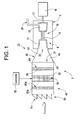
- Turbomachine system 2 includes a turbomachine housing 4 having an interior portion 6 within which is arranged a turbomachine 10.
- Turbomachine 10 includes a compressor portion 12 that is operatively connected to a turbine portion 13 via a shaft 14 which, in turn, is connected to an electrical power generator 16 via a shaft 17.
- Compressor portion 12 includes a compressor intake 20 that receives a flow of air through an intake system 22. That is, air flowing through intake system 22 passes directly to compressor intake 20, while exhaust gases generated by turbomachine 10 pass from turbomachine housing 4 via an exhaust system 25.
- intake system 22 includes an intake member or duct 40 having a first end portion 42 that extends from turbomachine housing 4 to a second end portion 43 through an intermediate portion 44. Second end portion 43 is fluidly connected to a filter or filtration system 48 positioned upstream of compressor intake 20.
- Filtration system 48 depending on geographical constraints, removes various substances such as, particulate of various sizes, moisture, salt, and the like from a flow of air passing into intake 20.
- filtration system 48 includes an intake or inlet region 54 that receives a flow of "unclean" air, a filtration region 55 having a barrier or filtering device 56 for removing foreign objects/debris, and an outlet region 57 that delivers "clean" air to compressor intake 20.
- filtration system 48 includes a plurality of louvers 74 arranged at inlet region 54. Louvers 74 block large particles, debris, and the like from entering inlet region 54.
- filtration system 48 includes a first plurality of selectively positional vanes 80a - 80d ( FIGS. 3 and 4 ), arranged up-stream of filtering device 56.
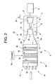
- Vanes 80a-80d are movable between a first position, such as shown in FIGS. 1 and 3 , to provide a barrier to incoming particles and/or water, and a second position, such as illustrated in FIGS. 2 and 4 , establishing an unobstructed flow path for incoming air passing to compressor intake 20. More specifically, when in the first position, vanes 80a - 80d remove a first amount of foreign particles or particulate from the incoming air at a first pressure drop. When in the second position, vanes 80a -80d remove a second amount of foreign particles or particulate from the incoming air at a second, lower pressure drop.
- vanes 80a - 80d create a flow restriction that results in a pressure drop of the air flowing through filtration system 48 into compressor intake 20.
- vanes 80a-80d are movable about a central vertical axis (not separately labeled) between the first and second positions.
- Each vane 80a-80d includes a corresponding entrapment or blocking surface 82a-82d that, when in the first position, is selectively positioned across inlet region 54 at various orientations/angular positions depending upon environmental conditions.
- blocking surfaces 82a-82d are curvilinear in order to maximize contact surface area while still maintaining a narrow profile. In any event, by positioning vanes 80a - 80d across inlet region 54 as shown in FIG.
- blocking surfaces 82a - 82d present a large contact surface area that is exposed to incoming air so as to trap most, if not all, particles entering intake system 22. However, the large contact surface area creates a correspondingly high pressure drop of air passing into compressor intake 20. Accordingly, vanes 80a - 80d are selectively positionable between the first position and the second position. When in the second position, blocking surfaces 82a - 82d present a smaller contact surface area that is exposed to the incoming airstream such that any pressure drop is minimized.
- vanes 80a-80d are shifted to the first position such that blocking surfaces 82a-82d are positioned to block and/or entrap water/dust and/or other particles entering inlet region 54.
- the particles are carried away from vanes 80a-80d via ducts (not shown) that lead to a collection area or drain (also not shown).
- vanes 80a-80d are shifted to the second position to provide a substantially unobstructed flow path to compressor intake 20.
- blocking surfaces 82a-82d are substantially parallel to incoming airflow.
- vanes 80a-80d are shifted to anywhere between the first and second positions to maximize air flow into inlet region 54 while still providing a first level of defense for turbomachine 10.
- filtration system 48 includes a second plurality of selectively movable vanes, one of which is indicated at 84, arranged down-stream of filtering device 56.
- vanes 84 are movable between a first position, such as shown in FIGS. 1 and 3 , to present a large contact surface area that is exposed to incoming air and thus provide a barrier to incoming particles and/or water, and a second position, such as illustrated in FIGS. 2 and 4 , establishing minimizing exposure of the contact surface to the airflow they presenting an unobstructed flow path for incoming air passing to compressor intake 20.
- vanes 84 when in the first position, vanes 84 remove a first amount of foreign particles or particulate from the incoming air at a first pressure drop.
- vanes 84 When in the second position, vanes 84 remove a second amount of foreign particles or particulate from the incoming air at a second, lower pressure drop.
- vanes 84 are movable about a central vertical axis (not separately labeled) between the first and second positions.
- each vane 84 includes a corresponding entrapment or blocking surface 86 that, is selectively positioned across outlet region 57 at various orientations/angular positions depending upon environmental conditions.
- vanes 84 maintained in the first position such that blocking surfaces 86 are positioned to block and/or entrap water/dust and/or other particles entering inlet region 54.
- the particles are carried away from vanes 80a-80d via ducts (not shown) that lead to a collection area or drain (also not shown).
- vanes 84 actually serve as an added level of protection for turbomachine 10.
- vanes 84 are shifted to the second position to provide a substantially unobstructed flow path to compressor intake 20.
- Vanes 80a-80d and 84 can be manually shifted, or automatically shifted between the first and second positions, and anywhere in-between. That is, in accordance with one exemplary aspect of the invention, turbomachine system 2 includes a controller 90 operatively coupled to vanes 80a-80d and 84. In this manner, personnel positioned remote from filtration system 48 can adjust vanes 80a-80d and 84 as environmental conditions dictate. Moreover, vanes 80a-80d can be shifted independent of vanes 84 depending on environmental conditions. That is, depending on various environmental factors, vanes 80a-80d can be placed in the first or blocking position while vanes 84 remain in the second or open position. Once again, it should be understood, that vanes 80a-80d and 84 can also be selectively positioned anywhere between the first and second positions as conditions dictate.
- Controller 90 comprises any appropriate high-powered solid-state switching device. As illustrated, the controller 90 is represented as a computer. However, this is merely exemplary of an appropriate high-powered control, which is within the scope of the invention.
- controller 90 comprises at least one of a silicon controlled rectifier (SCR), a thyristor, MOS-controlled thyristor (MCT) and an insulated gate bipolar transistor.
- SCR silicon controlled rectifier
- MCT MOS-controlled thyristor
- controller 90 is implemented as a single special purpose integrated circuit, such as ASIC, having a main or central processor section for overall, system-level control, and separate sections dedicated performing various different specific combinations, functions and other processes under control of the central processor section.
- controller 90 can also be implemented using a variety of separate dedicated or programmable integrated or other electronic circuits or devices, such as hardwired electronic or logic circuits including discrete element circuits or programmable logic devices, such as PLDs, PALs, PLAs or the like. Controller 90 can also be implemented using a suitably programmed general-purpose computer, such as a microprocessor or microcontrol, or other processor device, such as a CPU or MPU, either alone or in conjunction with one or more peripheral data and signal processing devices. In general, any device or similar devices on which a finite state machine capable of implementing the flow charts, as illustrated in the application can be used as controller 90. As shown a distributed processing architecture is a preferred for maximum data/signal processing capability and speed.
- exemplary embodiments of the invention provide an apparatus for enhancing turbomachine operation.
- turbomachine efficiency is enhanced. That is, air flow into turbomachine is enhanced across all operating conditions to provide enhanced performance.
- particular positioning of the vanes can vary. That is, the vanes can be mounted at the inlet region, before the filtering device, aft of the filtering device or both before and aft of the filtering device depending upon local conditions/geographical constraints.
- the number and geometry (shape) of the vanes can vary in accordance with exemplary embodiments of the invention.
Landscapes
- Engineering & Computer Science (AREA)
- Mechanical Engineering (AREA)
- General Engineering & Computer Science (AREA)
- Structures Of Non-Positive Displacement Pumps (AREA)
Abstract
A turbomachine 2 includes a compressor 12 having a compressor intake 20, and an intake system 2 mounted upstream of the compressor intake. The intake system 22 includes a housing and a plurality of selectively positionable vanes 80,84 arranged within the housing. The plurality of selectively positionable vanes 80,84 are moveable between a first position to remove a first amount of foreign particles, and a second position, to remove a second amount of foreign particles.
Description
- The present invention relates generally to the art of turbomachines and, more particularly, to an adaptable intake system for a turbomachine.
- Modem turbomachines include a number or rotating components that operate within tight tolerances. Foreign matter ingested into the turbomachine can cause damage, excessive wear, or even catastrophic failure. Thus, turbomachines are provided with various systems to remove foreign particulate and moisture from intake airstreams. Geographical constraints dictate particulate and moisture removal levels for turbomachines. Machines operating in a relatively dry, clean environment require a lower level or degree of particulate removal as compared with machines operating in harsh environments such as, off-shore oil rigs, mobile and/or marine uses.
- The geographical constraint(s) is a determining factor for inlet design when seeking optimal performance from the turbomachine. The geographical constraint(s) also becomes a limitation when constraining factors, such as dust, rain, foreign debris, and the like are not present on a continuing basis. Existing systems employ fixed filtering devices or barriers that screen particulate from intake airstreams. While effective during times when particulate is present, the fixed devices represent a flow restriction that limits intake air volume and, as a consequence, turbomachine efficiency during times when particulate levels are low.
- According to a first aspect of the present invention a turbomachine includes a compressor having a compressor intake, and an intake system mounted upstream of the compressor intake. The intake system includes a housing and a plurality of selectively positionable vanes arranged within the housing. The plurality of selectively positionable vanes are moveable between a first position to removes a first amount of foreign particles, and a second position, to removes a second amount of foreign particles.
- In accordance with an exemplary embodiment of the present invention, a method of controlling airflow for a turbomachine includes positioning a plurality of vanes, shiftably mounted at the intake system, between a first position, and a second position. When in the first position, the plurality of vanes remove a first amount of foreign particles, and when in the second position, the plurality of vanes remove a second amount of foreign particles.
- In accordance with yet another exemplary embodiment of the invention, an intake system for a turbomachine includes a housing, and a plurality of selectively positionable vanes arranged within the housing. The plurality of selectively positionable vanes are moveable between a first position to removes a first amount of foreign particles, and a second position to removes a second amount of foreign particles.
- Additional features and advantages are realized through the techniques of exemplary embodiments of the present invention. Other embodiments and aspects of the invention are described in detail herein and are considered a part of the claimed invention. For a better understanding of the invention with advantages and features, refer to the description and to the drawings, in which:
-
FIG. 1 is a schematic view of a turbomachine system including an adaptable intake system in accordance with exemplary embodiments of the invention illustrating a plurality of selectively movable vanes in a first position; -
FIG. 2 is a schematic view of the turbomachine system ofFIG. 1 illustrating the plurality of selectively movable vanes in a second position; -
FIG. 3 is a top, schematic view of the plurality of selectively movable vanes in the first position; and -
FIG. 4 is a top, schematic view of the plurality of selectively movable vanes in the second position. - With reference to
FIGS. 1 and2 , a turbomachine system, constructed in accordance with exemplary embodiments of the invention, is indicated generally at 2.Turbomachine system 2 includes aturbomachine housing 4 having aninterior portion 6 within which is arranged aturbomachine 10.Turbomachine 10 includes acompressor portion 12 that is operatively connected to aturbine portion 13 via ashaft 14 which, in turn, is connected to anelectrical power generator 16 via ashaft 17.Compressor portion 12 includes acompressor intake 20 that receives a flow of air through anintake system 22. That is, air flowing throughintake system 22 passes directly tocompressor intake 20, while exhaust gases generated byturbomachine 10 pass fromturbomachine housing 4 via anexhaust system 25. - In accordance with the exemplary embodiment shown,
intake system 22 includes an intake member orduct 40 having afirst end portion 42 that extends fromturbomachine housing 4 to asecond end portion 43 through anintermediate portion 44.Second end portion 43 is fluidly connected to a filter orfiltration system 48 positioned upstream ofcompressor intake 20.Filtration system 48, depending on geographical constraints, removes various substances such as, particulate of various sizes, moisture, salt, and the like from a flow of air passing intointake 20. Towards that end,filtration system 48 includes an intake orinlet region 54 that receives a flow of "unclean" air, afiltration region 55 having a barrier orfiltering device 56 for removing foreign objects/debris, and anoutlet region 57 that delivers "clean" air tocompressor intake 20. In addition,filtration system 48 includes a plurality oflouvers 74 arranged atinlet region 54. Louvers 74 block large particles, debris, and the like from enteringinlet region 54. - In further accordance with the exemplary embodiment of the invention,
filtration system 48 includes a first plurality of selectivelypositional vanes 80a - 80d (FIGS. 3 and 4 ), arranged up-stream offiltering device 56. Vanes 80a-80d are movable between a first position, such as shown inFIGS. 1 and3 , to provide a barrier to incoming particles and/or water, and a second position, such as illustrated inFIGS. 2 and4 , establishing an unobstructed flow path for incoming air passing tocompressor intake 20. More specifically, when in the first position, vanes 80a - 80d remove a first amount of foreign particles or particulate from the incoming air at a first pressure drop. When in the second position, vanes 80a -80d remove a second amount of foreign particles or particulate from the incoming air at a second, lower pressure drop. - That is, when in the first position, vanes 80a - 80d create a flow restriction that results in a pressure drop of the air flowing through
filtration system 48 intocompressor intake 20. - In the exemplary embodiment shown,
vanes 80a-80d are movable about a central vertical axis (not separately labeled) between the first and second positions. Eachvane 80a-80d includes a corresponding entrapment or blockingsurface 82a-82d that, when in the first position, is selectively positioned acrossinlet region 54 at various orientations/angular positions depending upon environmental conditions. In the exemplary embodiment shown, blockingsurfaces 82a-82d are curvilinear in order to maximize contact surface area while still maintaining a narrow profile. In any event, by positioning vanes 80a - 80d acrossinlet region 54 as shown inFIG. 3 , blockingsurfaces 82a - 82d present a large contact surface area that is exposed to incoming air so as to trap most, if not all, particles enteringintake system 22. However, the large contact surface area creates a correspondingly high pressure drop of air passing intocompressor intake 20. Accordingly,vanes 80a - 80d are selectively positionable between the first position and the second position. When in the second position, blockingsurfaces 82a - 82d present a smaller contact surface area that is exposed to the incoming airstream such that any pressure drop is minimized. - More specifically, when environmental conditions require extra filtering, such as, but not limited to, during high seas, storms, high particulate days, sandstorms, and the like,
vanes 80a-80d are shifted to the first position such that blockingsurfaces 82a-82d are positioned to block and/or entrap water/dust and/or other particles enteringinlet region 54. The particles are carried away fromvanes 80a-80d via ducts (not shown) that lead to a collection area or drain (also not shown). When environmental conditions change,vanes 80a-80d are shifted to the second position to provide a substantially unobstructed flow path tocompressor intake 20. When in the second position, blockingsurfaces 82a-82d are substantially parallel to incoming airflow. Moreover, depending upon environmental conditions,vanes 80a-80d are shifted to anywhere between the first and second positions to maximize air flow intoinlet region 54 while still providing a first level of defense forturbomachine 10. - In accordance with another exemplary embodiment of the invention,
filtration system 48 includes a second plurality of selectively movable vanes, one of which is indicated at 84, arranged down-stream offiltering device 56. In a manner similar to that described above,vanes 84 are movable between a first position, such as shown inFIGS. 1 and3 , to present a large contact surface area that is exposed to incoming air and thus provide a barrier to incoming particles and/or water, and a second position, such as illustrated inFIGS. 2 and4 , establishing minimizing exposure of the contact surface to the airflow they presenting an unobstructed flow path for incoming air passing tocompressor intake 20. More specifically, in a manner similar to that described above, when in the first position, vanes 84 remove a first amount of foreign particles or particulate from the incoming air at a first pressure drop. When in the second position, vanes 84 remove a second amount of foreign particles or particulate from the incoming air at a second, lower pressure drop. In the exemplary embodiment shown,vanes 84 are movable about a central vertical axis (not separately labeled) between the first and second positions. In any event, eachvane 84 includes a corresponding entrapment or blockingsurface 86 that, is selectively positioned acrossoutlet region 57 at various orientations/angular positions depending upon environmental conditions. - In a manner also similar to that described above, when environmental conditions require extra filtering, such as, but not limited to, during high seas, storms, high particulate days, sandstorms, and the like,
vanes 84 maintained in the first position such that blockingsurfaces 86 are positioned to block and/or entrap water/dust and/or other particles enteringinlet region 54. The particles are carried away fromvanes 80a-80d via ducts (not shown) that lead to a collection area or drain (also not shown). In this manner,vanes 84 actually serve as an added level of protection forturbomachine 10. However, when environmental conditions change/improve,vanes 84 are shifted to the second position to provide a substantially unobstructed flow path tocompressor intake 20. - Vanes 80a-80d and 84 can be manually shifted, or automatically shifted between the first and second positions, and anywhere in-between. That is, in accordance with one exemplary aspect of the invention,
turbomachine system 2 includes acontroller 90 operatively coupled tovanes 80a-80d and 84. In this manner, personnel positioned remote fromfiltration system 48 can adjustvanes 80a-80d and 84 as environmental conditions dictate. Moreover,vanes 80a-80d can be shifted independent ofvanes 84 depending on environmental conditions. That is, depending on various environmental factors,vanes 80a-80d can be placed in the first or blocking position whilevanes 84 remain in the second or open position. Once again, it should be understood, thatvanes 80a-80d and 84 can also be selectively positioned anywhere between the first and second positions as conditions dictate. -
Controller 90 comprises any appropriate high-powered solid-state switching device. As illustrated, thecontroller 90 is represented as a computer. However, this is merely exemplary of an appropriate high-powered control, which is within the scope of the invention. For example but not limiting of the invention,controller 90 comprises at least one of a silicon controlled rectifier (SCR), a thyristor, MOS-controlled thyristor (MCT) and an insulated gate bipolar transistor. In the illustrated exemplary embodiment,controller 90 is implemented as a single special purpose integrated circuit, such as ASIC, having a main or central processor section for overall, system-level control, and separate sections dedicated performing various different specific combinations, functions and other processes under control of the central processor section. It will be appreciated by those skilled in the art thatcontroller 90 can also be implemented using a variety of separate dedicated or programmable integrated or other electronic circuits or devices, such as hardwired electronic or logic circuits including discrete element circuits or programmable logic devices, such as PLDs, PALs, PLAs or the like.Controller 90 can also be implemented using a suitably programmed general-purpose computer, such as a microprocessor or microcontrol, or other processor device, such as a CPU or MPU, either alone or in conjunction with one or more peripheral data and signal processing devices. In general, any device or similar devices on which a finite state machine capable of implementing the flow charts, as illustrated in the application can be used ascontroller 90. As shown a distributed processing architecture is a preferred for maximum data/signal processing capability and speed. - In any event, at this point it should be understood that exemplary embodiments of the invention provide an apparatus for enhancing turbomachine operation. By providing a system that is selectively controlled to prevent foreign particles and liquid/moisture from being ingested by a turbomachine during harsh operating conditions, yet allowing a full flow of intake air during nominal operating conditions without requiring labor intensive filter system modifications, turbomachine efficiency is enhanced. That is, air flow into turbomachine is enhanced across all operating conditions to provide enhanced performance. It should also be understood that the particular positioning of the vanes can vary. That is, the vanes can be mounted at the inlet region, before the filtering device, aft of the filtering device or both before and aft of the filtering device depending upon local conditions/geographical constraints. Moreover the number and geometry (shape) of the vanes can vary in accordance with exemplary embodiments of the invention.
- In general, this written description uses examples to disclose the invention, including the preferred mode, and also to enable any person skilled in the art to practice the invention, including making and using any devices or systems and performing any incorporated methods. The patentable scope of the invention is defined by the claims, and may include other examples that occur to those skilled in the art. Such other examples are intended to be within the scope of exemplary embodiments of the present invention if they have structural elements that do not differ from the literal language of the claims, or if they include equivalent structural elements with insubstantial differences from the literal language of the claims.
- Various aspects and embodiments of the present invention are now defined by the following numbered clauses:
- 1. A turbomachine comprising:
- a compressor including a compressor intake; and
- an intake system mounted upstream of the compressor intake, the intake system including a housing and a plurality of selectively positionable vanes arranged within the housing, the plurality of selectively positionable vanes being moveable between a first position to remove a first amount of foreign particles, and a second position to remove a second amount of foreign particles.
- 2. The turbomachine according to clause 1, wherein the intake system includes an inlet region, the plurality of selectively positionable vanes being arranged at the inlet region.
- 3. The turbomachine according to any preceding clause, wherein each of the plurality of selectively positionable vanes includes an entrapment surface, the entrapment surface blocking, at least in part, foreign matter from entering the compressor intake when the plurality of selectively positionable vanes are in the first position.
- 4. The turbomachine according to any preceding clause, wherein each entrapment surface is curvilinear.
- 5. The turbomachine according to any preceding clause, further comprising: a control operatively connected to the plurality of selectively positionable vanes, the control being adapted to shift the plurality of selectively positionable vanes between the first and second position.
- 6. The turbomachine according to any preceding clause, further comprising: a filtering device arranged within the intake system.
- 7. The turbomachine according to preceding clause, wherein the plurality of vanes are arranged up-stream of the filtering device.
- 8. The turbomachine according to any preceding clause, wherein the plurality of vanes are arranged down-stream of the filtering device.
- 9. The turbomachine according to any preceding clause, wherein the plurality of vanes comprises a first plurality of vanes arranged up-stream of the filtering device and a second plurality of vanes arranged down-stream of the filtering device.
- 10. The turbomachine according to any preceding clause, wherein each of the first and second plurality of vanes is separately controllable.
- 11. A method of controlling airflow through an intake system for a turbomachine, the method comprising:
- positioning a plurality of vanes shiftably mounted at the intake system between a first position, and a second position, wherein when in the first position, the plurality of vanes remove a first amount of foreign particles, and wherein when in the second position, the plurality of vanes remove a second amount of foreign particles.
- 12. The method according to clause 11, wherein, when in the first position, partially blocking an inlet of the intake system with entrapment surfaces provided on each of the plurality of vanes.
- 13. The method of
clause 11 or 12, further comprising: automatically shift the plurality of vanes between the first and second positions. - 14. The method of any of clauses 11 to 13, further comprising: passing an airflow through a filtering device arranged within the intake system.
- 15. The method of any of clauses 11 to 14, wherein when in the first position, the plurality of vanes substantially block foreign particles from entering the turbomachine up-stream of the filtering device.
- 16. The method of any of clauses 11 to 15, wherein when in the first position, the plurality of vanes substantially block foreign particles from entering the turbomachine down-stream of the filtering device.
- 17. The method of any of clauses 11 to 16, wherein when in the first position, the plurality of vanes substantially block foreign particles from entering the turbomachine up-stream and down-stream of the filtering device.
- 18. The method of any of clauses 11 to 17, further comprising: independently controlling a first plurality of vanes arranged up-stream of the filtering device and a second plurality of vanes arranged down-stream of the filtering device.
- 19. The method of any of clauses 11 to 18, wherein positioning the plurality of vanes shiftably mounted at the intake system anywhere between the first position, and the second position comprises rotating the plurality of vanes about a vertical axis.
- 20. An intake system for a turbomachine comprising:
- a housing; and
- a plurality of selectively positionable vanes arranged within the housing, the plurality of selectively positionable vanes being moveable between a first position to remove a first amount of foreign particles, and a second position to remove a second amount of foreign particles.
Claims (15)
- A turbomachine (2) comprising:a compressor (12) including a compressor intake (20); andan intake system (22) mounted upstream of the compressor intake, the intake system including a housing and a plurality of selectively positionable vanes (80,84) arranged within the housing, the plurality of selectively positionable vanes (80,84) being moveable between a first position to remove a first amount of foreign particles, and a second position to remove a second amount of foreign particles.
- The turbomachine (2) according to claim 1, wherein the intake system includes an inlet region, the plurality of selectively positionable vanes (80,84) being arranged at the inlet region.
- The turbomachine (2) according to any preceding claim, wherein each of the plurality of selectively positionable vanes (80,84) includes an entrapment surface, the entrapment surface blocking, at least in part, foreign matter from entering the compressor intake when the plurality of selectively positionable vanes are in the first position.
- The turbomachine (2) according to claim 3, wherein each entrapment surface is curvilinear.
- The turbomachine (2) according to any preceding claim, further comprising: a control operatively connected to the plurality of selectively positionable vanes (80,84), the control being adapted to shift the plurality of selectively positionable vanes between the first and second position.
- The turbomachine (2) according to any preceding claim, further comprising: a filtering device (48) arranged within the intake system.
- The turbomachine (2) according to any preceding claim, wherein each of the first and second plurality of vanes (80,84) is separately controllable.
- A method of controlling airflow through an intake system (22) for a turbomachine (2), the method comprising:positioning a plurality of vanes (80,84) shiftably mounted at the intake system (22) between a first position, and a second position, wherein when in the first position, the plurality of vanes remove a first amount of foreign particles, and wherein when in the second position, the plurality of vanes remove a second amount of foreign particles.
- The method according to claim 8, wherein, when in the first position, partially blocking an inlet of the intake system (22) with entrapment surfaces provided on each of the plurality of vanes (80,84).
- The method of claim 8 or 9, further comprising: automatically shift the plurality of vanes (80,84) between the first and second positions.
- The method of any of claims 8 to 10, further comprising: passing an airflow through a filtering device (48) arranged within the intake system (22).
- The method of any of claims 8 to 11, wherein when in the first position, the plurality of vanes (80,84) substantially block foreign particles from entering the turbomachine (2) up-stream of the filtering device.
- The method of any of claims 8 to 12, wherein when in the first position, the plurality of vanes (80,84) substantially block foreign particles from entering the turbomachine (2) down-stream of the filtering device.
- The method of any of claims 8 to 13, wherein positioning the plurality of vanes (80,84) shiftably mounted at the intake system anywhere between the first position, and the second position comprises rotating the plurality of vanes about a vertical axis.
- An intake system (22) for a turbomachine (2) comprising:a housing; and a plurality of selectively positionable vanes (80,84) arranged within the housing, the plurality of selectively positionable vanes being moveable between a first position to remove a first amount of foreign particles, and a second position to remove a second amount of foreign particles.
Applications Claiming Priority (1)
| Application Number | Priority Date | Filing Date | Title |
|---|---|---|---|
| US12/172,342 US8061973B2 (en) | 2008-07-14 | 2008-07-14 | Turbomachine including an adaptable intake system and method of controlling airflow to a turbomachine |
Publications (1)
| Publication Number | Publication Date |
|---|---|
| EP2146098A2 true EP2146098A2 (en) | 2010-01-20 |
Family
ID=41151900
Family Applications (1)
| Application Number | Title | Priority Date | Filing Date |
|---|---|---|---|
| EP09164965A Withdrawn EP2146098A2 (en) | 2008-07-14 | 2009-07-08 | Turbomachine including an adaptable intake system and method of controlling airflow to a turbomachine |
Country Status (5)
| Country | Link |
|---|---|
| US (1) | US8061973B2 (en) |
| EP (1) | EP2146098A2 (en) |
| CN (1) | CN101629519A (en) |
| AU (1) | AU2009202757A1 (en) |
| CA (1) | CA2671465A1 (en) |
Cited By (1)
| Publication number | Priority date | Publication date | Assignee | Title |
|---|---|---|---|---|
| ITCO20100068A1 (en) * | 2010-12-23 | 2012-06-24 | Nuovo Pignone Spa | FILTER CHAMBER AND METHOD TO MAINTAIN THE SAME |
Families Citing this family (3)
| Publication number | Priority date | Publication date | Assignee | Title |
|---|---|---|---|---|
| EP2824285B1 (en) * | 2013-07-11 | 2016-03-16 | Alstom Technology Ltd | Gas turbine engine comprising an inlet flow control arrangement |
| RU2621923C9 (en) * | 2015-12-30 | 2018-11-15 | Акционерное общество "Московский вертолетный завод им. М.Л. Миля" | Cyclone |
| US20180306112A1 (en) * | 2017-04-20 | 2018-10-25 | General Electric Company | System and Method for Regulating Flow in Turbomachines |
Family Cites Families (3)
| Publication number | Priority date | Publication date | Assignee | Title |
|---|---|---|---|---|
| FR2707338B1 (en) * | 1993-07-07 | 1995-08-11 | Snecma | Variable camber turbomachine blade. |
| EP1362984B1 (en) * | 2002-05-16 | 2007-04-25 | ROLLS-ROYCE plc | Gas turbine engine |
| FR2853930B1 (en) | 2003-04-16 | 2007-02-23 | Snecma Moteurs | DEVICE FOR THE CONTROL OF VARIABLE-SETTING AUBES IN A TURBOMACHINE |
-
2008
- 2008-07-14 US US12/172,342 patent/US8061973B2/en active Active
-
2009
- 2009-07-08 EP EP09164965A patent/EP2146098A2/en not_active Withdrawn
- 2009-07-08 AU AU2009202757A patent/AU2009202757A1/en not_active Abandoned
- 2009-07-09 CA CA002671465A patent/CA2671465A1/en not_active Abandoned
- 2009-07-14 CN CN200910165103A patent/CN101629519A/en active Pending
Cited By (3)
| Publication number | Priority date | Publication date | Assignee | Title |
|---|---|---|---|---|
| ITCO20100068A1 (en) * | 2010-12-23 | 2012-06-24 | Nuovo Pignone Spa | FILTER CHAMBER AND METHOD TO MAINTAIN THE SAME |
| WO2012084892A1 (en) * | 2010-12-23 | 2012-06-28 | Nuovo Pignone S.P.A. | Filtering chamber and method for maintaining same |
| US9863317B2 (en) | 2010-12-23 | 2018-01-09 | Marco Santini | Filtering chamber and method for maintaining same |
Also Published As
| Publication number | Publication date |
|---|---|
| CA2671465A1 (en) | 2010-01-14 |
| US8061973B2 (en) | 2011-11-22 |
| CN101629519A (en) | 2010-01-20 |
| US20100008763A1 (en) | 2010-01-14 |
| AU2009202757A1 (en) | 2010-01-28 |
Similar Documents
| Publication | Publication Date | Title |
|---|---|---|
| US8061973B2 (en) | Turbomachine including an adaptable intake system and method of controlling airflow to a turbomachine | |
| EP0497574A1 (en) | Fan case treatment | |
| KR20170134281A (en) | A Filtering Apparatus for an Intake Air of a System of Air Management | |
| CN102635446A (en) | Turbine inlet air filter system | |
| EP2674688A2 (en) | Air Treatment Apparatus and System Comprised Thereof | |
| EP3485163A1 (en) | Cooling a wind turbine generator | |
| CN108266337B (en) | Wind turbine generator set and cooling method thereof | |
| RU2009144987A (en) | MOVABLE AIR OUTLET DEVICE FOR AIRCRAFT | |
| EP4124737A1 (en) | System and method for inhibiting particulate and foreign object ingress in combustion systems | |
| RU2007100625A (en) | INTEGRATED AIR CLEANING DEVICE (CLE) FOR CLEANING CYCLIC AIR OF A GAS-TURBINE INSTALLATION | |
| WO2019095129A1 (en) | Cooling system and method for motor and controller | |
| JP7237456B2 (en) | Systems and methods for regulating flow in turbomachinery | |
| KR20120008870A (en) | Variable Intake Air Cleaner | |
| KR20110004021A (en) | Noise Reduction Inertial Filter | |
| US7217184B2 (en) | Electrical generator fluid-flow-coolant filtration method | |
| CN114087088A (en) | Aeroengine test casing and aeroengine test system | |
| RU2414611C2 (en) | Complex air cleaning device | |
| JPS62168999A (en) | Axial flow compressor extraction device | |
| CN110064615A (en) | A kind of runner cleaning device and cleaning method | |
| CN116651616B (en) | Metal fluoride capturer and excimer laser | |
| CN107725120B (en) | Dustproof device and aircraft engine | |
| KR20170044227A (en) | A Filtering Apparatus for an Intake Air of a System of Air Management | |
| CN205277576U (en) | Dust collector of engine radiator | |
| RU2467209C2 (en) | Air bleed device, compressor stage with said device, compressor with said stage, and turbojet with said compressor | |
| CN113685374A (en) | Mixed flow fan, air conditioning equipment and household appliance |
Legal Events
| Date | Code | Title | Description |
|---|---|---|---|
| PUAI | Public reference made under article 153(3) epc to a published international application that has entered the european phase |
Free format text: ORIGINAL CODE: 0009012 |
|
| AK | Designated contracting states |
Kind code of ref document: A2 Designated state(s): AT BE BG CH CY CZ DE DK EE ES FI FR GB GR HR HU IE IS IT LI LT LU LV MC MK MT NL NO PL PT RO SE SI SK SM TR |
|
| STAA | Information on the status of an ep patent application or granted ep patent |
Free format text: STATUS: THE APPLICATION IS DEEMED TO BE WITHDRAWN |
|
| 18D | Application deemed to be withdrawn |
Effective date: 20120201 |