EP2145836A2 - Vorrichtung und Verfahren zur Herstellung eines Pakets - Google Patents
Vorrichtung und Verfahren zur Herstellung eines Pakets Download PDFInfo
- Publication number
- EP2145836A2 EP2145836A2 EP09165607A EP09165607A EP2145836A2 EP 2145836 A2 EP2145836 A2 EP 2145836A2 EP 09165607 A EP09165607 A EP 09165607A EP 09165607 A EP09165607 A EP 09165607A EP 2145836 A2 EP2145836 A2 EP 2145836A2
- Authority
- EP
- European Patent Office
- Prior art keywords
- package
- formers
- carton
- closing
- holding means
- Prior art date
- Legal status (The legal status is an assumption and is not a legal conclusion. Google has not performed a legal analysis and makes no representation as to the accuracy of the status listed.)
- Withdrawn
Links
- 238000004519 manufacturing process Methods 0.000 title 1
- 238000007789 sealing Methods 0.000 claims abstract description 46
- 230000007246 mechanism Effects 0.000 claims abstract description 36
- 230000015572 biosynthetic process Effects 0.000 claims abstract description 7
- 230000003068 static effect Effects 0.000 claims description 47
- 239000003292 glue Substances 0.000 claims description 26
- 238000004026 adhesive bonding Methods 0.000 claims description 22
- 238000004806 packaging method and process Methods 0.000 claims description 19
- 238000000034 method Methods 0.000 claims description 16
- 230000002829 reductive effect Effects 0.000 claims description 2
- 230000001419 dependent effect Effects 0.000 claims 1
- 239000000853 adhesive Substances 0.000 description 13
- 230000001070 adhesive effect Effects 0.000 description 13
- 238000010276 construction Methods 0.000 description 13
- 230000006835 compression Effects 0.000 description 9
- 238000007906 compression Methods 0.000 description 9
- 239000011087 paperboard Substances 0.000 description 8
- 230000008569 process Effects 0.000 description 7
- 239000000463 material Substances 0.000 description 6
- 239000002131 composite material Substances 0.000 description 4
- 239000000835 fiber Substances 0.000 description 4
- 239000011888 foil Substances 0.000 description 4
- 230000009286 beneficial effect Effects 0.000 description 3
- 241001489212 Tuber Species 0.000 description 2
- 230000008901 benefit Effects 0.000 description 2
- 230000001681 protective effect Effects 0.000 description 2
- 230000002787 reinforcement Effects 0.000 description 2
- 230000000717 retained effect Effects 0.000 description 2
- 239000002966 varnish Substances 0.000 description 2
- 239000004831 Hot glue Substances 0.000 description 1
- 239000012141 concentrate Substances 0.000 description 1
- 230000008878 coupling Effects 0.000 description 1
- 238000010168 coupling process Methods 0.000 description 1
- 238000005859 coupling reaction Methods 0.000 description 1
- 238000003780 insertion Methods 0.000 description 1
- 230000037431 insertion Effects 0.000 description 1
- 230000000670 limiting effect Effects 0.000 description 1
- 238000012858 packaging process Methods 0.000 description 1
- 238000002360 preparation method Methods 0.000 description 1
- 238000007639 printing Methods 0.000 description 1
- 230000000750 progressive effect Effects 0.000 description 1
- 238000007493 shaping process Methods 0.000 description 1
- 230000001360 synchronised effect Effects 0.000 description 1
Images





Classifications
-
- B—PERFORMING OPERATIONS; TRANSPORTING
- B65—CONVEYING; PACKING; STORING; HANDLING THIN OR FILAMENTARY MATERIAL
- B65B—MACHINES, APPARATUS OR DEVICES FOR, OR METHODS OF, PACKAGING ARTICLES OR MATERIALS; UNPACKING
- B65B7/00—Closing containers or receptacles after filling
- B65B7/16—Closing semi-rigid or rigid containers or receptacles not deformed by, or not taking-up shape of, contents, e.g. boxes or cartons
- B65B7/18—Closing semi-rigid or rigid containers or receptacles not deformed by, or not taking-up shape of, contents, e.g. boxes or cartons by collapsing mouth portion and subsequently folding-down or securing flaps
-
- B—PERFORMING OPERATIONS; TRANSPORTING
- B65—CONVEYING; PACKING; STORING; HANDLING THIN OR FILAMENTARY MATERIAL
- B65B—MACHINES, APPARATUS OR DEVICES FOR, OR METHODS OF, PACKAGING ARTICLES OR MATERIALS; UNPACKING
- B65B7/00—Closing containers or receptacles after filling
- B65B7/16—Closing semi-rigid or rigid containers or receptacles not deformed by, or not taking-up shape of, contents, e.g. boxes or cartons
- B65B7/20—Closing semi-rigid or rigid containers or receptacles not deformed by, or not taking-up shape of, contents, e.g. boxes or cartons by folding-down preformed flaps
-
- B—PERFORMING OPERATIONS; TRANSPORTING
- B65—CONVEYING; PACKING; STORING; HANDLING THIN OR FILAMENTARY MATERIAL
- B65D—CONTAINERS FOR STORAGE OR TRANSPORT OF ARTICLES OR MATERIALS, e.g. BAGS, BARRELS, BOTTLES, BOXES, CANS, CARTONS, CRATES, DRUMS, JARS, TANKS, HOPPERS, FORWARDING CONTAINERS; ACCESSORIES, CLOSURES, OR FITTINGS THEREFOR; PACKAGING ELEMENTS; PACKAGES
- B65D33/00—Details of, or accessories for, sacks or bags
- B65D33/007—Details of, or accessories for, sacks or bags for facilitating the separation of the two walls, e.g. walls of inequal height, tabs; for maintaining the mouth of the sack or bag open
-
- B—PERFORMING OPERATIONS; TRANSPORTING
- B65—CONVEYING; PACKING; STORING; HANDLING THIN OR FILAMENTARY MATERIAL
- B65D—CONTAINERS FOR STORAGE OR TRANSPORT OF ARTICLES OR MATERIALS, e.g. BAGS, BARRELS, BOTTLES, BOXES, CANS, CARTONS, CRATES, DRUMS, JARS, TANKS, HOPPERS, FORWARDING CONTAINERS; ACCESSORIES, CLOSURES, OR FITTINGS THEREFOR; PACKAGING ELEMENTS; PACKAGES
- B65D33/00—Details of, or accessories for, sacks or bags
- B65D33/02—Local reinforcements or stiffening inserts, e.g. wires, strings, strips or frames
-
- B—PERFORMING OPERATIONS; TRANSPORTING
- B65—CONVEYING; PACKING; STORING; HANDLING THIN OR FILAMENTARY MATERIAL
- B65D—CONTAINERS FOR STORAGE OR TRANSPORT OF ARTICLES OR MATERIALS, e.g. BAGS, BARRELS, BOTTLES, BOXES, CANS, CARTONS, CRATES, DRUMS, JARS, TANKS, HOPPERS, FORWARDING CONTAINERS; ACCESSORIES, CLOSURES, OR FITTINGS THEREFOR; PACKAGING ELEMENTS; PACKAGES
- B65D5/00—Rigid or semi-rigid containers of polygonal cross-section, e.g. boxes, cartons or trays, formed by folding or erecting one or more blanks made of paper
- B65D5/02—Rigid or semi-rigid containers of polygonal cross-section, e.g. boxes, cartons or trays, formed by folding or erecting one or more blanks made of paper by folding or erecting a single blank to form a tubular body with or without subsequent folding operations, or the addition of separate elements, to close the ends of the body
- B65D5/10—Rigid or semi-rigid containers of polygonal cross-section, e.g. boxes, cartons or trays, formed by folding or erecting one or more blanks made of paper by folding or erecting a single blank to form a tubular body with or without subsequent folding operations, or the addition of separate elements, to close the ends of the body with end closures formed by inward-folding of self-locking flaps hinged to tubular body
-
- B—PERFORMING OPERATIONS; TRANSPORTING
- B65—CONVEYING; PACKING; STORING; HANDLING THIN OR FILAMENTARY MATERIAL
- B65D—CONTAINERS FOR STORAGE OR TRANSPORT OF ARTICLES OR MATERIALS, e.g. BAGS, BARRELS, BOTTLES, BOXES, CANS, CARTONS, CRATES, DRUMS, JARS, TANKS, HOPPERS, FORWARDING CONTAINERS; ACCESSORIES, CLOSURES, OR FITTINGS THEREFOR; PACKAGING ELEMENTS; PACKAGES
- B65D5/00—Rigid or semi-rigid containers of polygonal cross-section, e.g. boxes, cartons or trays, formed by folding or erecting one or more blanks made of paper
- B65D5/42—Details of containers or of foldable or erectable container blanks
- B65D5/56—Linings or internal coatings, e.g. pre-formed trays provided with a blow- or thermoformed layer
- B65D5/60—Loose, or loosely attached, linings
- B65D5/603—Flexible linings loosely glued to the wall of the container
- B65D5/606—Bags or bag-like tubes loosely glued to the wall of a "tubular" container
-
- B—PERFORMING OPERATIONS; TRANSPORTING
- B65—CONVEYING; PACKING; STORING; HANDLING THIN OR FILAMENTARY MATERIAL
- B65B—MACHINES, APPARATUS OR DEVICES FOR, OR METHODS OF, PACKAGING ARTICLES OR MATERIALS; UNPACKING
- B65B7/00—Closing containers or receptacles after filling
- B65B7/02—Closing containers or receptacles deformed by, or taking-up shape, of, contents, e.g. bags, sacks
- B65B7/06—Closing containers or receptacles deformed by, or taking-up shape, of, contents, e.g. bags, sacks by collapsing mouth portion, e.g. to form a single flap
- B65B7/08—Closing containers or receptacles deformed by, or taking-up shape, of, contents, e.g. bags, sacks by collapsing mouth portion, e.g. to form a single flap and folding
Definitions
- the invention relates to an apparatus for constructing a package. More specifically, but not exclusively, the invention relates an apparatus for and method of finishing the construction of a package comprising a primary container and a carton.
- the present invention seeks to provide a beneficial apparatus compared to the prior art by providing an apparatus for constructing a carton and package containing delicate items.
- the invention provides an apparatus for closing a package comprising a moveable holding means for supporting and moving the package; at least two moveable formers and a closing mechanism, the at least two formers being moveable relative to one another from an open position, wherein the moveable holding means can be deployed to position the package between the formers and hold the package stationery therebetween and a closed position wherein the formers act on the package to manipulate the package into a closed position, the closing mechanism operable to secure the package in said closed position thereby to complete the formation of a closed package.
- one of said formers and said closing mechanism are coupled together and thereby moveable as a single unit along said common guide track.
- an edge of one or each of said formers is alignable with a pre-marked crease or fold line of a package to be closed.
- a lower 'T'-shaped edge portion of one of said formers is structured and arranged to mate with an upper edge portion of another of said formers such that a portion of a package sandwiched therebetween is caused to fold.
- said moveable holding means is structured and arranged to provide support to the package to retain the package substantially stationery during the processing effected by said formers.
- the holding means is of sufficient height to provide support to a flexible container held within the package.
- the closing mechanism comprises a pivotal portion operable to cause downward folding of a portion of the package for closing the package.
- the pivotal portion is 'L' shaped and an axle through the corner portion of the 'L' shaped pivotal portion couples the pivotal portion to said former.
- the holding means and formers are operable together to support and hold the package in three dimensions.
- a second aspect of the invention provides a method of closing a part-formed package comprising:
- a further aspect of the invention provides an apparatus for closing a package, the apparatus comprising a moveable holding means for supporting a package at a first location thereof and forming means for acting upon said package at a second location spaced from said first location, said moveable holding means operable to transfer the package in an open condition to said forming means, the forming means comprising at least two guiding members for bringing together upper portions of the package.
- the invention provides an apparatus for closing a package comprising a top-loaded carton having upper sealing panels, the apparatus comprising a moveable holding means for supporting and moving the package; at least two formers and a cover flap closing mechanism, the moveable holding means being deployable to position the package between the at least two formers and the package and at least two formers being moveable relative to one another to manipulate the upper sealing panels from an open position wherein the upper sealing panels are spaced apart to a sealed position wherein the upper sealing panels are in a contacting position, the closing mechanism operable to secure the package in said sealed position thereby to complete the formation of the package, the holding means being of sufficient height to provide support to a flexible container held within the package.
- the moveable holding means comprises a pair of lugs disposed on a conveyor means, said lugs being shaped in complimentary fashion to the shape of a lower portion of the package for supporting the package and where one or both of said lugs is of sufficient height to provide support to a flexible container held within the package.
- a gluing mechanism (G1) is disposed proximate said at least two formers for applying glue to one or both of the sealing panels (30, 32) such that in the contacting position, the sealing panels (30, 32) are adhered directly together or are adhered to an adjacent portion of the flexible container.
- the at least two formers comprise two static guides having progressively reduced spacing such that as the movable holding means conveys the package between the two static guides, the relative movement therebetween reduces the spacing between the sealing panels of the package and brings the sealing panels into a contacting position.
- one of said formers and said closing mechanism are coupled together and thereby moveable as a single unit along said common guide track.
- a lower 'T'-shaped edge portion of one of said formers is structured and arranged to mate with an upper edge portion of another of said formers such that a portion of a package sandwiched therebetween is caused to fold.
- the closing mechanism comprises a pair of static guides (206a, 206b) shaped and positioned to cause downward folding of a cover flap (34) of the package for closing the package as the movable holding means (216a, 216b) conveys the package alongside said static guides (206a, 206b).
- the closing mechanism comprises a pivotal portion operable to cause downward folding of a cover flap of the package for closing the package.
- the pivotal portion is 'L' shaped and an axle through the corner portion of the 'L' shaped pivotal portion couples the pivotal portion to said former.
- the invention provides a method of closing a part-formed package comprising a top-loaded carton having upper sealing panels, the method comprising:
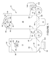
- Figure 1 shows a blank 10 which is foldable to form a carton for containing a secondary container 8 (see Figure 2B ).
- a package 6 comprising the carton and secondary container 8 is shown in Figure 2A .
- the blank 10 is formed of paperboard; any suitable foldable sheet material can be used to form the blank 10.
- the blank 10 is foldable into a partially-formed flat folded carton (not shown) that is provided to a converting plant where the partially-formed flat folded carton is erected into an open form; loaded with the secondary container 8 and closed to form the finished package 6 shown in Figure 2A . Further detail regarding the lay-out of blank 10 and the specific constructional steps required to assemble blank 10 into a carton are provided below.
- the blank 10 comprises the following series of panels: a back panel 12; first bottom closure panel 20; first side panel 14; front panel 16; cover flap 35; second bottom closure panel 24; second side panel 18; glue flap 104 and closure panels 22, 26.
- the main panels of the blank 10 are connected along fold lines (depicted in Figure 1 by dashed lines) 40, 44, 50, 62, 64, 66, 72, 74/76 and 78/80.
- fold line 38 comprises an interrupted series of cut lines to enable the second panel 32 to be foldable in a 360° rotation.
- the cover flap 35 comprises: a first panel 30; engaging tab 37 and pull tab 36.
- the cover flap 35 is hinged by fold line 62 to front panel 16.
- First panel 30 is also hinged by fold line 60 to portion 34 of the cover flap.
- Portion 28 of the cover flap is provided with angled lines of demarcation or fold lines 56 and 54. These angled lines of demarcation 56, 54 converge at cutline 58.
- Cutline 58 defines the engaging tab 37 or first part of a locking mechanism 37. Cutline 58 terminates at each end in an arcuate cut 102 which curves oppositely to the main portion of cut line 58.
- the front panel 12 comprises a bonding region 90 defined by a half-depth cut line 88; a second part of a locking mechanism 84 is provided by an aperture 84 defined by cutline 86 and nick cuts 92 disposed at both upper edges of aperture 84.
- the illustrated blank 10 is formed from a coated material and the coated side enables for the printing of graphics.
- the varnish-free patches 98 and 100 are prepared in this manner so that upon assembling the blank 10 into a carton, glue, adhesive or other bonding means can be applied to these areas and a secure bond will be achieved.
- the varnish free areas are depicted by cross-hatching.
- the blank 10 shown in figure 1 is "varnished side" or “coated side” facing out and shows areas where preferably adhesive, glue or other bonding means is applied onto the opposite, non-coated, side of the blank 10 during the construction of the blank 10 into a carton.
- These gluing areas 94, 96 are depicted by diagonal lines.
- crease lines 42, 46, 48, 68, 70 are provided. In providing these lines, the blank 10 can be part-formed and then transported in an efficient manner to a converting plant where apparatus of the present invention is used to complete the construction of such a carton or a similar carton.
- First bottom closure panel 20 is folded upwardly about fold line 40 into face contacting relationship with back panel 12.
- glue panel 106 is folded about fold line 42 into overlapping relationship with first bottom closure panel 20.
- Fold line 42 preferably comprises an alternating cut - crease line arrangement.
- Closure panels 22, 26 and second bottom closure panel 24 are also folded upwardly about respective fold lines 74/76, 78/80 and 64 into flat face contacting relationship with the respective side panel 14, 18 and back panel 16.
- Glue flap 104, together with half of closure panel 26 is then folded about fold lines 68/70 into overlapping relationship with the other half of closure panel 26 and a portion of back panel 16. Glue is then applied optionally in the configurations 94 and 96 as shown.
- the back panel 16 together with half of first side panel 14 and the folded second side panel 18 is then folded about crease line 46/48 such that cross-hatched (non-varnished) portions 100, 98 of the glue flap 104 and second bottom closure panel 24 are overlaid onto glued areas 94 and 96 respectively.
- the above described steps of construction can be performed in a straight line machine where rotation of the blank 10 during construction is not required.
- rotation of the blank 10 during construction is not required.
- the above sequence of folding and gluing operations is optional and construction of a carton from the blank 10 may be achieved in a number of ways.
- the flat-formed partially constructed carton formed after performing the above described steps is then supplied to another packaging line such as that to be described, wherein the carton is opened.
- the partially constructed carton is opened by bringing together the creased portions 46 and 68 of first and second side panels 14 and 18. This results in the automatic set-up of a composite base wall 20, 24, 22, and 26. As the composite base wall 20, 24, 22, 26 is formed, the front panel 12 and back panel 16 are spaced apart. The upper portion of the carton is thereby ready to receive a secondary container 8.
- the secondary container 8 is a sachet or pouch, containing articles such as truffles.
- the secondary container 8 is shown in Figure 2B .
- First and second portions S1, S2 are joined together by a seal S.
- the secondary container comprises a closed base portion and sides adjoining the first and second portions S1, S2. It will be understood that such a secondary container 8 is likely to be flexible, non rigid and intended for containing delicate, soft or easily damaged articles that need to be well sealed within the secondary container 8. Once the articles are retained, the secondary container needs to be handled carefully to avoid damaging or spoiling of the goods contained therein.
- the secondary container 8 is formed from a foil lined sheet material.
- the secondary container 8 (illustrated in an opened position in Figure 10 ) may be formed by sealing both ends of a cylindrical shaped portion of foil lined sheet material. At least one end of the secondary container is sealed by bonding together first and second portions S1, S2, which portions extend (upwardly) beyond the plane of the seal S.
- the sealed secondary container 8 or sachet may be assembled loaded and sealed in a separate process. Alternatively, the construction of the secondary container 8; its loading and sealing may be performed in the same processing machine as that to be described.
- the sealed secondary container 8 is loaded through the top, open end of the carton, between the front and back panels 12, 16.
- the secondary container is then disposed within the carton and the secondary container 8 rests on the composite bottom wall 20, 22, 24, 26.
- the weight of the secondary container 8 can be used to maintain the composite bottom wall 20, 22, 24, 26 in a flat-set up condition, in which lower ends of the front and back panels 12, 16 are fixedly spaced apart.
- the seal S of the secondary container 8 is shown in Figure 6 .
- the first and second portions S1, S2 of the secondary container 8 that extend beyond the seal are denoted by S1 and S2 (see Figure 8 ).
- the first and second portions S1, S2 are bonded to the first and second panels 30, 32.
- This bonding step preferably is performed after the secondary container 8 has been loaded and sealed and placed within the carton. Bonding first portion S1 to first panel 30 and bonding second portion S2 to second panel 32 is optional, though preferable.
- the first and second panels 30, 32 reinforce the secondary package in a region of focussed stress when the secondary package is being manipulated to break the seal, by pulling the first and second portions S1, S2 apart. Nevertheless, even without bonding the first and second portions S1, S2 to the first and second panels 30, 32, the first and second panels 30, 32 provide a more resilient and less flexible grasping point and provide reinforcement to the first and second portions S1, S2 of the foil secondary container 8.
- the construction of package 6 can be completed.
- the construction is completed by bringing together the first and second panels 30, 32 (and thus sandwiching the first and second portions S1, S2, there between); applying glue to bonding region 90 or to the cover flap 35 and then folding the cover flap 35 and second panel 32 about fold lines 62 and 38 respectively.
- the second panel 32 is thereby disposed in face contacting relationship with the front panel 16 and the cover flap 35 is thereby disposed in face contacting relationship with, and bonded to, the front panel 16.
- the completed package 6 is shown in Figure 2A .
- the package 6 is opened by breaking the bond between cover flap 35 and bonding region 90.
- pull tab 36 defined by arcuate crease line 52 is optionally provided.
- the pull tab 36 can be grasped and used to lift the cover flap 35 away from the front panel 12.
- the bonding region 90 by being defined by a half-depth cut 88 is weakened and the when the cover flap 35 is lifted, the fibre bond of the paperboard in the bonding region fails before the adhesive bond between the cover flap and bonding region 90 does.
- the half-depth cut 88 enables the fibre bond of the paperboard to break and the cover flap 35 is then foldable about fold line 62 to open the package 6.
- the optionally weakened arrangement 88 the fibre-bond is encouraged to break without the cover flap 35 tearing, breaking or being damaged in any other way which would prevent it being used for re-closing the carton.
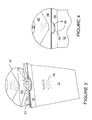
- the opened package is shown in Figures 3 and 4 . It can be seen that where the fibre bond of the paperboard has broken in the bonding region 90, paperboard has been removed from the bonding region 90 and can be seen attached to the cover flap 35. (The bonding region 90 defined by half-depth cut line 88 is optional and alternatively in other embodiments a weaker adhesive bond may be used which will break before the fibre bond of the paperboard). Other securing means for attaching the cover flap 35 to the front panel 12 which can then be broken without reducing the usefulness of the cover flap 35 for re-closing the carton can be used.
- the cut-out defined by arcuate cut 82 can be used to separate the second panel 32 and first panel 30.
- FIG. 5 - 8 the method of opening the secondary container using the carton is illustrated.
- a consumer grips first panel 30 and first portion S1 with a first hand H1 and simultaneously grips second panel 32 and second portion S2 using a second hand H2.
- Fold lines 38 and 62 are substantially parallel or aligned with the seal S.
- the seal S can be cleanly broken and the secondary container 8 opened, as shown in Figures 8 - 10 .
- the opening O created by breaking the seal S is shown in Figure 9 .
- the first and second panels 30, 32 together with the body of the carton, provide reinforcement and a guide to encourage the seal S to break cleanly. Ripping or tearing of the secondary package in an undesirable manner, that could result in the spilling of articles for example truffles from the secondary container 8, is avoided or at least mitigated by the carton controlling the distribution of the pulling forces applied to the secondary container 8. Additionally the crease lines 38 and 62 by being substantially parallel to the seal S serve to prevent the forces applied to break the seal S from being dissipated past the seal S and serve to concentrate the applied pulling forces onto the seal S itself.
- a second optional aspect of this exemplary package is a reclosing mechanism that may provide a sufficiently tight re-seal to minimise perishing of the contents.
- first and second portions S1, S2 of the secondary container are sandwiched between the first and second panels 30, 32 (see Figure 11 ) and then the cover flap and second panel 32 are folded into face contacting relationship with the front panel 16.
- the angled lines of demarcation 56, 54 can then be deployed to manipulate the first part of a locking mechanism, in this illustration, locking tab 37, (defined by cutline 58) into engagement with the second part of the locking mechanism, (in this illustration aperture 84 and nick cuts 92) thereby engaging and locking together the cover panel 35 with the front panel 16.
- the re-closed package 6 is shown in Figure 12 .
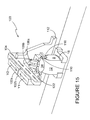
- FIG. 13-16 a first exemplary apparatus for constructing a package such as the aforedescribed package 6 is shown. It will be understood upon reading the foregoing that the apparatus described may be used to construct carton packages having alternative construction to that shown in Figures 1 - 12 . Additionally it will be understood that the apparatus shown represents one exemplary embodiment of the present invention and does not therefore represent an exhaustive description of all ways the apparatus of the present invention can be implemented.
- the apparatus 100 is shown in Figure 13 .
- the apparatus comprises a holding means 114 which comprises front supporting portions 116a/116b, each optionally provided to support the package being assembled by the apparatus 100.
- the shape and structure of the holding means 114 is in other embodiments different to that shown here and is constructed to provide sufficient support to the opened package and preferably a flexible secondary container 8. As such a taller and/or more flexible secondary container 8 may require a holding means 114 of greater height than that illustrated here in order that a greater support is provided.
- the holding means is constructed such that it does not interfere (by catching or engaging for example) with the rest of the apparatus 100.
- the holding means 114 is moveable along a track or conveyor means in direction X.
- the carton is supplied to the apparatus (which apparatus may be a subassembly forming part of a larger packaging line) in an opened condition and with sealed secondary container 8 already disposed therein.
- the apparatus has a secondary container sealing and/or filling means for filling and/or sealing the secondary container in conjunction with the closing and sealing of the carton.
- Apparatus 100 comprises closing means 102a; 102b.
- Closing means 102a; 102b are slidably mounted to mount 104. It is preferably for the closing means 102a; 102b to be mounted to the same mount 104 to ensure that when moving relative to one another their travel is directed along the same path. In this way it is ensured that the closing means 102a; 102b will meet one another for closing the carton.
- the mount 104 is preferably coupled to a housing 112 which supports the mount 104.
- Rotating members 106a; 106b are coupled to closing means 102a and a static guide 110 or fold support means 110 is coupled to closing means 102b by means of a mounting member 122.
- the rotating members 106a; 106b are pivotally mounted to axle or pin 108 and preferably are coupled to guiding portions 120, 118 which as well as coupling the rotating members to the closing means 102a; form part of a support for the rotating members 106a; 106b and also are shaped and sized to act as guide for the carton/package when disposed in or on the moveable housing means 114 and disposed between the rotating members 106a; 106b and static guide 110 or fold support means 110. In this way alignment of the carton/package with the rotating means 106a; 106b, and static guide is ensured before further processing on the carton/package is performed.
- the carton package is moved past a hot glue or other adhesive mechanism as is known in the art.
- This gluing mechanism is utilised to apply glue to the front wall 12 of the carton (depicted by two spots in Figures 13 and 14 ).
- the position of the static guide 110; guiding portions 120, 118; and rotating members 106a; 106b is adjustable such that these components of the apparatus 100 can be moved into a position wherein they are properly aligned with the carton/package. In this way, different sized packages may be accommodated by the apparatus 100 and also accurate folding for closing of the carton/package is achievable.
- the closing means 102a; 102b are moved relatively toward one another and in doing so, the static guide 110 is brought towards the rotating members 106a; 106b and guiding portions 118, 120.
- the opened carton/package is sandwiched therebetween as shown in Figure 5 .
- glue and/or other adhesive means is applied to the carton front wall at a position beneath the static guide 110 so that the static guide remains clean and free from adhesive which could affect its operation.
- an upper edge of static guide 110 is aligned with fold line 38 of the carton front wall 12 and similarly an upper edge of guiding portions 118, 120 is aligned with fold line 62 of the back panel 16.
- the static guide 110 is sized in depth approximately equal to the depth of first panel 30 of the carton 6.
- the lower edge of the static guide 110 is tapered such that one end of the static guide 110 is narrower to facilitate its withdrawal from the carton, once the cover flap 35 and first and second panels 30, 32 have been folded to deal the carton.
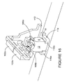
- the rotating members 106a; 106b are operated simultaneously and are pivoted about pin 108 to come into contact with and fold downwardly portion 34 of the cover flap 35 and first panel 30.
- the rotating members 106a; 106b are right angle shaped and the pin 108 is coupled to the rotating members 106a; 106b at this corner joint such that a foot portion of the rotating member 106a; 106b is brought into contact with the cover flap 35 and is rotated in direction Z (see Figure 16 ) until the cover flap 35 is disposed in flat face contacting relationship and is adhered to front wall 12.
- the rotating members 106a; 106b are mounted on an optional 'T'-shaped bar.
- This 'T'-shaped bar or former is shaped to help form the carton package into is final construction.
- the static guide 110 preferably fits against the 'T'-shaped portion to assist the cover flap 35 folding accurately along fold line 62 such that when the rotating members 106a;106b are caused to act on the first panel 30 and portion 34 of the cover flap 35, the cover flap 35 is accurately folded.
- the guiding portions 118, 120; 'T'-shaped former; and static guide 110 support the carton package during the rotation of the rotating members 106a, 106b such that the fragile, flexible and/or delicate contents of the secondary container 8 are protected during the closure of the carton.
- the rotating members are lifted and the closing means 102a moved, by relative movement, in direction Y1 as shown in Figure 17 .
- the guiding portions 118, 120 and 'T;-shaped former are withdrawn from the packages.
- the holding means 114 is again moved in direction X and in doing so the carton is moved off the static guide 110.
- the closing means 102b is moved in direction Y2 (see Figure 17 ) and the subassembly 100 is ready to receive a subsequent package for closing.
- subassembly 100 described represents one exemplary format of a component comprised within a packaging line that may also attend to the following optional steps that are not presented in any specific order.
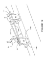
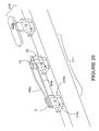
- FIG. 18 A second embodiment of the apparatus according to the invention is shown in Figures 18 to 20 .
- Like reference numerals have been used, were appropriate to highlight features of the second illustrated embodiment that are similar to features of the first embodiment. To distinguish between the embodiments, the numerals have been prefixed with the number '2'.
- a container 8 in feed Part-formed carton blanks are provided on a conveyor element and are each conveyed by a holding means through the packaging line.
- the packaging line comprises an opening and loading section 205; first closing and gluing station 207; compression station 209; second folding and gluing station 211 and final compression station 213.
- the holding means comprises a pair of lugs 216a, 216b coupled to a conveyor means such as an endless belt or lug chain. Upright portions of the pair of lugs 216a, 216b support the side walls 14, 18 of the carton.
- the lugs 216a, 216b are disposed opposite to one another and the trailing lug 216a of the pair serves to push and thereby convey the carton through the apparatus.
- the trailing lug 216a is preferably higher to provide support to the carton near to the top, but not too close to interfere with the closing and sealing process. In other embodiments both lugs 216a, 216b will be similar in height. Providing further support up the height of the carton helps to maintain the front and rear panels 12, 16 in good, parallel alignment. One higher lug 216a is sufficient to achieve this.
- the high lug is the rear lug, the one that pushes the carton through the packaging system since it is this pushing force that ensures the edges of panels 12 and 16 are parallel and together.
- the timing of the movement of the lugs 216a, 216b is therefore synchronised to ensure that the pitch or spacing between them remains constant such that the carton is retained between the lugs 216a, 216b and thereby supported.
- the lugs 216a, 216b are preferably shaped, as illustrated, to match the shape of the carton package to ensure that the carton and contents 6 are well supported.
- the lugs 216a, 216b are optionally removable and replaceable with different shaped lugs so that different carton shapes and formats can be accommodated by the packaging line.
- the carton in the holding means 216a, 216b is conveyed either side of a pair of static guides 240a, 240b.
- the static guides 240a, 240b are narrow so that the front and rear carton panels 12, 16 can pass on the outside of the outside of them.
- the static guides 240a, 240b diverge in the downstream direction.
- the static guides 230a, 230b are gradually spaced further apart until the spacing of the front and rear panels 12, 16 matches the depth of the bottom structure of the carton and the carton is held in an open condition.
- Top loading means such as robot arms with suction holders could be used to facilitate this step, no specific means is illustrated and it will be understood that any suitable means known in the art could be employed.
- the loaded carton After exiting the opening and loading section 205, the loaded carton is conveyed downstream by the holding means 216a, 216b to the first closing and gluing station 207.
- the entrance to the first closing and gluing station 207 is spaced from the exit of the opening and loading section 205 in the illustrated example. This spacing may be changed to reduce the line length of the packaging line or varied to facilitate specific timing between the sections. In other embodiments it is envisaged that the entrance to the first closing and gluing station 207 is disposed immediately after the exit of the opening and loading section 205.
- the first closing and gluing station 207 is illustrated schematically in Figure 18 .
- a pair of static guides 230a, 230b are shaped and spaced to facilitate the bringing together of the front and rear panels.
- the guides are therefore more widely spaced at their entrance end.
- the entrance end of the guides will be funnel shaped so that the entrance is substantially wider than the carton to give a large tolerance and ensure that the carton does not contact or hit the guides.
- the static guides 230a, 230b illustrated are shaped and positioned to cause the carton to be closed along the line of fold lines 38 and 62.
- the carton is formed of paperboard or other recyclable, printable sheet material. It is also optional, though preferable, that the sealing is achieved by means of glue applied to panels of these cartons. Whereas it is envisaged that in some applications, the use of heat and/or pressure activated adhesive could be used to affect the sealing steps; the use of surface applied adhesive can be more economical. Also, the use of surface applied adhesive can be beneficial because the application position and adhesion point is accurately determined. However, the folding and manipulation steps need to be engineered in a careful manner when the apparatus contains surface applied glue. Any transfer of glue onto machine parts or onto cartons where it should not be present could cause serious damage to the machine and/or packages.
- Compression station 209 comprises a pair of rotating belts (only one is shown because to show the other belt would obscure the view of the carton).
- the belt shown is operated in a clockwise direction, the other belt in an anticlockwise direction. As such the belts encourage the carton to be fed between them.
- the belts are aligned with the first and second panels 30, 32 to apply pressure thereto and to sandwich portions S1, S2 of the container 8 between those panels 30, 32 in a secure manner. Thereafter the lugs 216a, 216b convey the nearly completed package to the second folding and gluing station 211.
- the second folding and gluing station 211 comprises a similar arrangement of static guides 206a, 206b.
- the entrance to the second folding and gluing station 211 is disposed downstream of the exit of the compression means 209. In other embodiments the entrance to second folding and gluing station 211 is disposed immediately adjacent to the exit of the compression means 209.
- the entrance between the guides 206a, 206b in other embodiments is significantly wider than the carton to allow a tolerance.
- the static guides 206a, 206b are not curved at the entrance.
- a glue applicator G2 is disposed to apply glue in the bonding region 90. In this second embodiment, the surface adhesive is applied directly to the front panel 12. In other envisaged embodiments the glue is applied to the cover flap 34. In such embodiments, the gluer G2 is disposed on the same side of the apparatus as the means for folding the cover flap 34. This is described in more detail below.
- the carton continues to be conveyed by lugs 216a, 216b between the static guides 206a, 206b.
- One of the static guides 206b provides a means for maintaining the carton in an aligned upright position as it is conveyed and provides a means for providing a force onto the carton in cooperation with the other static guide.
- the other static guide 206a is shaped progressively closer to static guide 206b in the horizontal plane and progressively higher than static guide 206b in the vertical plane.
- the cover flap 34 is automatically folded as it is conveyed by virtue of being in contact with the pair of static guides.
- the cover flap 34 is folded into contacting relationship with the adhesive on bonding region 90 and the carton package is complete.
- the final compression station 213 is provided. It operates in the same way as compression 209, with the carton being fed between rotating belts (only one shown for illustrative purposes) at a height aligned with the position of the applied glue.
- the specific nature of the components described and illustrated may take alternative formats and yet still perform their required functions, for example, in other embodiments the secondary foil wrapper is inserted into the opened carton blank and then filled with its contents.
- the sealing of the secondary container and/or adhesion of sealing portions of the secondary container to the carton and/or sealing the carton closed are performed in conjunction with one another so that only 1 to 3 stationary stages of the process are required.
- the intermittent machine only one or more than two rotating members are deployed.
- the specific shape of the housing 112 may take alternative forms, for example a framework.
- the static guide 110 and/or rotating member mount are in other embodiments moveable relative to one another by means of a closing means 102b, 102a having a format other than the slidable mounts as illustrated. Any suitable known mechanism for causing relative movement of parts could be deployed, including a piston driven guide
- the apparatus is configured such that the second gluing mechanism G2 is disposed immediately adjacent to the cover flap 35 of the carton and on the same side of the apparatus as the guide that performs the folding of the cover flap 35.
- the carton is folded, optionally by a series of suitably shaped and positioned static guides such that a "V-shape cross-section is formed between the cover flap 34 and panel 30.
- the surface of panel 34 that is to be adhered to front panel 12 provides the top-most outer-facing surface; and the other face of panel 34 is in overlapping contact with the outer surface of panel 30, with panel 30 being folded about fold line 62 into substantially perpendicular relationship with back panel 16.
- the apparatus of the invention is applicable to a variety of types of secondary container other than that shown, for example a semi-rigid container with a weak or flexible upper portion.
- the number and arrangement of panels to which the secondary container is bonded and/or the number of panels comprised in the carton closing means may differ.
- the carton comprises three panels and the secondary container has three portions which are bonded to the three panels and the apparatus comprises three guiding portions that are brought together to create a former between which the carton is shaped supported and held whilst a closing mechanism is deployed to secure a carton closure mechanism in place.
- the apparatus would comprise more than one pair of formers for sandwiching; shaping and securing the carton.
- hinged connection should not be construed, unless otherwise stated, as necessarily referring to a single fold line only; indeed it is envisaged that hinged connection can be formed from one or more of the following, a short slit, a frangible line and/or a fold line without departing from the scope of the invention.
Landscapes
- Engineering & Computer Science (AREA)
- Mechanical Engineering (AREA)
- Closing Of Containers (AREA)
Applications Claiming Priority (1)
| Application Number | Priority Date | Filing Date | Title |
|---|---|---|---|
| GB0812899A GB0812899D0 (en) | 2008-07-15 | 2008-07-15 | Apparatus for and method of making a package |
Publications (2)
| Publication Number | Publication Date |
|---|---|
| EP2145836A2 true EP2145836A2 (de) | 2010-01-20 |
| EP2145836A3 EP2145836A3 (de) | 2010-02-24 |
Family
ID=39722284
Family Applications (1)
| Application Number | Title | Priority Date | Filing Date |
|---|---|---|---|
| EP09165607A Withdrawn EP2145836A3 (de) | 2008-07-15 | 2009-07-15 | Vorrichtung und Verfahren zur Herstellung eines Pakets |
Country Status (2)
| Country | Link |
|---|---|
| EP (1) | EP2145836A3 (de) |
| GB (1) | GB0812899D0 (de) |
Family Cites Families (6)
| Publication number | Priority date | Publication date | Assignee | Title |
|---|---|---|---|---|
| GB549632A (en) * | 1940-08-20 | 1942-11-30 | Robert Morris Bergstein | Rotatable packaging machines and methods |
| US3313089A (en) * | 1964-10-07 | 1967-04-11 | Gen Mills Inc | Bag closing machine |
| US3483803A (en) * | 1967-10-23 | 1969-12-16 | Bergstein Packaging Trust | Automatic flap folding means for packaging apparatus |
| US4063403A (en) * | 1976-08-23 | 1977-12-20 | Bergstein Packaging Trust | Carton closing and sealing apparatus |
| US4236368A (en) * | 1979-01-02 | 1980-12-02 | The Interstate Folding Box Company | Carton closing and sealing apparatus for lined cartons and method of closing same |
| US6216943B1 (en) * | 2000-04-03 | 2001-04-17 | Smurfit-Stone Container Corporation | Fresh fold package |
-
2008
- 2008-07-15 GB GB0812899A patent/GB0812899D0/en not_active Ceased
-
2009
- 2009-07-15 EP EP09165607A patent/EP2145836A3/de not_active Withdrawn
Also Published As
| Publication number | Publication date |
|---|---|
| EP2145836A3 (de) | 2010-02-24 |
| GB0812899D0 (en) | 2008-08-20 |
Similar Documents
| Publication | Publication Date | Title |
|---|---|---|
| US10710760B2 (en) | Method for producing a package for cigarettes | |
| US8689530B2 (en) | Method and device for inserting (tube) bags into cartons | |
| US20050079965A1 (en) | Container forming machine | |
| JP5869304B2 (ja) | ヒンジ式蓋付きパッケージとヒンジ式蓋付きパッケージを製造する包装方法および包装機 | |
| CN103129759B (zh) | 包装袋式饮料容器用的纸箱、使包装闭合的机器和方法 | |
| EP0800475B1 (de) | Verpackungsvorrichtung für aufgestapelte papiererzeugnisse | |
| AU2007225409B2 (en) | Flat blank carton | |
| KR101252853B1 (ko) | 흡연물품 패킹 장치 및 방법 | |
| KR20130004390A (ko) | 내용물 유지 웨브가 부착된 컨테이너 블랭크 및 컨테이너 블랭크로부터 형성된 컨테이너 | |
| US7819791B1 (en) | Cartoner for cartons having concave sides | |
| CA2599227A1 (en) | Flexible easy-open package with reclosable feature | |
| WO2006023758A3 (en) | Wrap around carton packaging machine | |
| CN100408448C (zh) | 烟制品包装盒坯料、组件及其组装方法 | |
| JP4454158B2 (ja) | ケース、カット部材アセンブリ、ケースの開梱方法及びかかるケースの製造方法及び製造用機械 | |
| US10556396B2 (en) | Methods and a machine for forming a shelf-ready shipper display system | |
| US7475525B2 (en) | Method and device for producing packs from at least two partial packs | |
| TW202319309A (zh) | 包裝件 | |
| US7516599B2 (en) | Methods and apparatus for manufacture of a reclosable plastic carton | |
| WO2010059932A2 (en) | Carton with top gusset | |
| EP1194347B1 (de) | Verpackungsdose, verfahren und vorrichtung zur herstellung und anverwendung derselben | |
| US20050075230A1 (en) | Method and apparatus for forming multi-sided containers | |
| US11731386B2 (en) | System and method for processing case and carton blanks | |
| CN103732497A (zh) | 用于制造香烟的翻盖盒式包装的方法和设备 | |
| TW202146302A (zh) | 物品攜具、胚片及建構方法 | |
| EP2145836A2 (de) | Vorrichtung und Verfahren zur Herstellung eines Pakets |
Legal Events
| Date | Code | Title | Description |
|---|---|---|---|
| PUAI | Public reference made under article 153(3) epc to a published international application that has entered the european phase |
Free format text: ORIGINAL CODE: 0009012 |
|
| AK | Designated contracting states |
Kind code of ref document: A2 Designated state(s): AT BE BG CH CY CZ DE DK EE ES FI FR GB GR HR HU IE IS IT LI LT LU LV MC MK MT NL NO PL PT RO SE SI SK SM TR |
|
| AX | Request for extension of the european patent |
Extension state: AL BA RS |
|
| PUAL | Search report despatched |
Free format text: ORIGINAL CODE: 0009013 |
|
| AK | Designated contracting states |
Kind code of ref document: A3 Designated state(s): AT BE BG CH CY CZ DE DK EE ES FI FR GB GR HR HU IE IS IT LI LT LU LV MC MK MT NL NO PL PT RO SE SI SK SM TR |
|
| AX | Request for extension of the european patent |
Extension state: AL BA RS |
|
| 17P | Request for examination filed |
Effective date: 20100319 |
|
| 17Q | First examination report despatched |
Effective date: 20100414 |
|
| RAP1 | Party data changed (applicant data changed or rights of an application transferred) |
Owner name: MEADWESTVACO PACKAGING SYSTEMS LLC |
|
| RAP1 | Party data changed (applicant data changed or rights of an application transferred) |
Owner name: MEADWESTVACO PACKAGING SYSTEMS, LLC |
|
| STAA | Information on the status of an ep patent application or granted ep patent |
Free format text: STATUS: THE APPLICATION IS DEEMED TO BE WITHDRAWN |
|
| 18D | Application deemed to be withdrawn |
Effective date: 20110809 |