EP2145828A1 - Cardboard or like material box having a body and a cover obtained from a single punched and creased blank. - Google Patents
Cardboard or like material box having a body and a cover obtained from a single punched and creased blank. Download PDFInfo
- Publication number
- EP2145828A1 EP2145828A1 EP09008696A EP09008696A EP2145828A1 EP 2145828 A1 EP2145828 A1 EP 2145828A1 EP 09008696 A EP09008696 A EP 09008696A EP 09008696 A EP09008696 A EP 09008696A EP 2145828 A1 EP2145828 A1 EP 2145828A1
- Authority
- EP
- European Patent Office
- Prior art keywords
- longitudinal
- box
- glue
- crease line
- flap
- Prior art date
- Legal status (The legal status is an assumption and is not a legal conclusion. Google has not performed a legal analysis and makes no representation as to the accuracy of the status listed.)
- Granted
Links
Images


Classifications
-
- B—PERFORMING OPERATIONS; TRANSPORTING
- B65—CONVEYING; PACKING; STORING; HANDLING THIN OR FILAMENTARY MATERIAL
- B65D—CONTAINERS FOR STORAGE OR TRANSPORT OF ARTICLES OR MATERIALS, e.g. BAGS, BARRELS, BOTTLES, BOXES, CANS, CARTONS, CRATES, DRUMS, JARS, TANKS, HOPPERS, FORWARDING CONTAINERS; ACCESSORIES, CLOSURES, OR FITTINGS THEREFOR; PACKAGING ELEMENTS; PACKAGES
- B65D5/00—Rigid or semi-rigid containers of polygonal cross-section, e.g. boxes, cartons or trays, formed by folding or erecting one or more blanks made of paper
- B65D5/42—Details of containers or of foldable or erectable container blanks
- B65D5/54—Lines of weakness to facilitate opening of container or dividing it into separate parts by cutting or tearing
- B65D5/5405—Lines of weakness to facilitate opening of container or dividing it into separate parts by cutting or tearing for opening containers formed by erecting a blank in tubular form
- B65D5/5415—Lines of weakness to facilitate opening of container or dividing it into separate parts by cutting or tearing for opening containers formed by erecting a blank in tubular form the lines of weakness being provided in one or more closure flaps and in the container body so as to form after rupture a lid hinged to a side edge of the container body
-
- B—PERFORMING OPERATIONS; TRANSPORTING
- B65—CONVEYING; PACKING; STORING; HANDLING THIN OR FILAMENTARY MATERIAL
- B65D—CONTAINERS FOR STORAGE OR TRANSPORT OF ARTICLES OR MATERIALS, e.g. BAGS, BARRELS, BOTTLES, BOXES, CANS, CARTONS, CRATES, DRUMS, JARS, TANKS, HOPPERS, FORWARDING CONTAINERS; ACCESSORIES, CLOSURES, OR FITTINGS THEREFOR; PACKAGING ELEMENTS; PACKAGES
- B65D5/00—Rigid or semi-rigid containers of polygonal cross-section, e.g. boxes, cartons or trays, formed by folding or erecting one or more blanks made of paper
- B65D5/42—Details of containers or of foldable or erectable container blanks
- B65D5/54—Lines of weakness to facilitate opening of container or dividing it into separate parts by cutting or tearing
- B65D5/5405—Lines of weakness to facilitate opening of container or dividing it into separate parts by cutting or tearing for opening containers formed by erecting a blank in tubular form
- B65D5/542—Lines of weakness to facilitate opening of container or dividing it into separate parts by cutting or tearing for opening containers formed by erecting a blank in tubular form the lines of weakness being provided in the container body
- B65D5/5425—Lines of weakness to facilitate opening of container or dividing it into separate parts by cutting or tearing for opening containers formed by erecting a blank in tubular form the lines of weakness being provided in the container body and defining after rupture a lid hinged to the upper edge of the container body
-
- B—PERFORMING OPERATIONS; TRANSPORTING
- B65—CONVEYING; PACKING; STORING; HANDLING THIN OR FILAMENTARY MATERIAL
- B65D—CONTAINERS FOR STORAGE OR TRANSPORT OF ARTICLES OR MATERIALS, e.g. BAGS, BARRELS, BOTTLES, BOXES, CANS, CARTONS, CRATES, DRUMS, JARS, TANKS, HOPPERS, FORWARDING CONTAINERS; ACCESSORIES, CLOSURES, OR FITTINGS THEREFOR; PACKAGING ELEMENTS; PACKAGES
- B65D5/00—Rigid or semi-rigid containers of polygonal cross-section, e.g. boxes, cartons or trays, formed by folding or erecting one or more blanks made of paper
- B65D5/42—Details of containers or of foldable or erectable container blanks
- B65D5/64—Lids
- B65D5/66—Hinged lids
- B65D5/6602—Hinged lids formed by folding one or more extensions hinged to the upper edge of a tubular container body
- B65D5/6608—Hinged lids formed by folding one or more extensions hinged to the upper edge of a tubular container body the lid being held in closed position by self-locking integral flaps
-
- B—PERFORMING OPERATIONS; TRANSPORTING
- B65—CONVEYING; PACKING; STORING; HANDLING THIN OR FILAMENTARY MATERIAL
- B65D—CONTAINERS FOR STORAGE OR TRANSPORT OF ARTICLES OR MATERIALS, e.g. BAGS, BARRELS, BOTTLES, BOXES, CANS, CARTONS, CRATES, DRUMS, JARS, TANKS, HOPPERS, FORWARDING CONTAINERS; ACCESSORIES, CLOSURES, OR FITTINGS THEREFOR; PACKAGING ELEMENTS; PACKAGES
- B65D5/00—Rigid or semi-rigid containers of polygonal cross-section, e.g. boxes, cartons or trays, formed by folding or erecting one or more blanks made of paper
- B65D5/42—Details of containers or of foldable or erectable container blanks
- B65D5/64—Lids
- B65D5/66—Hinged lids
- B65D5/6602—Hinged lids formed by folding one or more extensions hinged to the upper edge of a tubular container body
- B65D5/6614—Hinged lids formed by folding one or more extensions hinged to the upper edge of a tubular container body with means for retaining the lid in open position
Definitions
- the present invention relates to the cardboard-packaging sector, and in particular concerns a box made from a single blank of cardboard, or the like material, and having a flip-top and snap-closing cover.
- a cardboard, or like material, box having a body and a cover obtained from a single punched and creased blank comprising a first blank portion intended to form the box body and a second blank portion intended to form the box cover, said first and second blank portions being joined by crease lines and, in the remainder, being separated by intermediate cut lines, wherein:
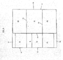
- Figure 1 there is shown a punched and creased cardboard blank from which a box according to the invention can be obtained.
- the blank comprises a first portion A, designed to form the box body, and a second portion B, designed to form the box cover.
- the aforesaid first and second portions A and B are joined by crease lines C and in the remainder they are separated by intermediate cut lines F.
- Blank portion A comprises a front panel 10, a rear panel 11, two side panels 12 and 13, and a glue flap 14, which are sequentially arranged and connected along parallel sides by transverse crease lines 15, 16, 17 and 18.
- Blank portion B comprises a front band 26 and side bands 27 and 28 connected along parallel sides by transverse crease lines 29 and 30.
- the front band 26 extends upwardly into a longitudinal flap 31, whilst the side bands 27 and 28 extend into side flaps 32 and 33, respectively.
- the aforesaid longitudinal flap 31 and side flaps 32 and 33 can be folded along a longitudinal crease line 34 and are made to adhere to flap 24 of the blank portion A to from a box cover.
- the front band 26 extends downwardly into a longitudinal glue tab 35, whilst the side bands 27 and 28 extend into corresponding glue tabs 36 and 37, respectively, which are in the shape of a right-angled triangle.
- Glue tab 35 and glue tabs 36 and 37 can be folded along a longitudinal crease line 38.
- Glue tab 35 which is designed to be adhered to band 26, is joined to panel 10 of the blank portion A by a crease line C and includes, adjacent to said crease line, a lip 39 which is separable therefrom along a tear line 40.
- a connecting membrane 41 and 42 extends obliquely and downwardly and is joined by a crease line C to a corresponding one of the side panels 12 and 13 of the blank portion A.
- Each connecting membrane 41 and 42 includes a glue flap 43 and 44, which is separable therefrom along a tear line 45 and 46, respectively, and is further joined at its upper portion to a corresponding one of the side bands 27 and 28, along a length of the longitudinal crease line 38.
- a glue line is firstly applied to glue tab 35 and to glue tabs 36 and 37, then the glue tabs 35, 36 and 37 are rotated upwardly about crease line 38 to overlap each of them exactly on a corresponding one of the bands 26, 27 and 28, respectively, so as to form, on the face of the blank opposite to that shown in Figure 1 , a cuff portion R, which can be seen in phantom lines in Figure 2 of the drawings, for the purpose of stiffening the box cover.
- the first step for forming the box structure according to the invention terminates at this point.
- the boxes in the flattened condition, as shown in Figure 4 can be packed on each other for shipment to the user, which, by means of known and commonly used automatic machines, gives the boxes their final three-dimensional configuration, in order to receive the products to be contained therein.
- the box can be closed by rotating and gluing to each other the longitudinal flaps 24 and 31 and the side flaps 32 and 33 to form the box cover, which is thereby hinged to the box body along crease line 25 of the longitudinal flap 24.
- the second step for forming the box structure according to the invention and for packaging the products to be contained therein is terminated.
- the user grips the lower edge of the cuff R and pulls it upwardly to cause the separation of the lip 39 from the glue tab 35 along the tear line 40.
- the cover remains hinged to the panel 11 of the box body along crease line 25 and can be further rotated upwards and backwards with respect to panel 11, as shown in Figure 6 of the drawings.
- the opening rotation movement of the box cover about crease line 25 causes the separation of the connecting membranes 41 and 42 from the corresponding glue flaps 43 and 44 along tear lines 45 and 46, respectively, whereby the connecting membranes can rotate concurrently with the box cover about crease lines C and S.
- the connecting membranes 41 and 42 are caused, at first, to bend, then they spring back to the original flat shape, causing thereby the box cover to automatically flip open, and they are capable of keeping the box cover in the open position, in order to permit the user to access the products contained in the box.
- the connecting membranes 41 and 42 are caused, at first, to bend into a curvilinear shape, then they spring back to the original flat shape, causing the box cover to automatically flip in the closing position.
- lip 39 is pressed inwardly by the lower edge of the cuff R and, therefore, it can releasably latch to a step portion 47 formed by the glue stripe 35 along the tear line 40, whereby an unintentional opening of the cover is prevented.
- the cover is capable of ensuring a secure snap-closure of the box.
- the box has a simple structure and construction, and that it can be used to package various kinds of products and to provide always a easy access to the products contained. Furthermore, the stiffening cuff gives greater strength to the box compared to other structure known in the art.
Abstract
Description
- The present invention relates to the cardboard-packaging sector, and in particular concerns a box made from a single blank of cardboard, or the like material, and having a flip-top and snap-closing cover.
- There are known boxes made of cardboard, or the like material, and provided with a flip-top and snap-closing cover. In a conventional embodiment thereof, such boxes are obtained from a single blank of cardboard, in which cut lines and crease lines define a first portion designed to form the box body and a second portion designed to form the box cover.
DE 75 33 244 U discloses a structure according to the preamble ofclaim 1. It is an object of the present invention to make a box of the kind indicated above, which is improved over the prior art, both in respect of the production and use thereof. - The above object is achieved, according to the invention, with a cardboard, or like material, box having a body and a cover obtained from a single punched and creased blank comprising a first blank portion intended to form the box body and a second blank portion intended to form the box cover, said first and second blank portions being joined by crease lines and, in the remainder, being separated by intermediate cut lines, wherein:
- said first blank portion comprises a front panel, a rear panel, two side panels, and a glue flap, sequentially arranged and connected along parallel sides by transverse crease lines,
- said front panel and said rear panel extend downwardly into longitudinal flaps and said side panels into side flaps, respectively, said longitudinal flaps and said side flaps being foldable along a longitudinal crease line and being made to overlap and adhere to one another to form a box bottom,
- said rear panel extends upwardly into a longitudinal flap which is foldable along a longitudinal crease line,
- said second blank portion comprises a front band and two side bands connected along parallel sides by transverse crease lines,
- said front band extends upwardly into a longitudinal flap and said side bands into side flaps, respectively, said longitudinal flap and said side flaps being foldable along a longitudinal crease line and being made to adhere to the longitudinal flap of said rear panel of said first blank portion to form a box cover,
- said front band extends downwardly into a longitudinal glue tab and said side bands into glue tabs in the shape of a right-angled triangle, respectively, said longitudinal glue tab and each of said glue tabs in the shape of a right-angled triangle being foldable along a longitudinal crease line and being made to adhere to said front band and to a corresponding one of said side bands, respectively, to form, in co-operation therewith, a cuff for stiffening the cover,
- said longitudinal glue tab is joined to the front panel of said first blank portion by a crease line and includes, adjacent to said crease line, a lip which is separable therefrom along a tear line,
- a connecting membrane extends obliquely and downwardly from a crease line along the hypotenuse of each of said glue tabs in the shape of a right-angled triangle,
- said connecting membrane is joined, at its lower edge, to a corresponding one of said side panels of the first blank portion by a crease line,
- said connecting membrane includes a glue flap which is separable therefrom along a tear line and is further joined, at its upper edge, to a corresponding one of said side bands, along a length of said longitudinal crease line, said glue flap being foldable along said longitudinal crease line and being made to adhere to said corresponding one of said side bands.
- For the purpose of illustrating the structure and the features of a box according to the invention, a preferred, although non-limiting embodiment thereof will be now described in more detail, with reference to the accompanying drawings, wherein:
-
Figures 1 to 4 show a punched and creased cardboard blank, in a flat, unfolded state and in the sequential folding steps for forming a box according to the present invention; -
Figure 5 is a perspective view of the box in the final three-dimensional state, for receiving the products to be contained therein; and -
Figure 6 is a perspective view of the finished box with the cover in the open condition. - In
Figure 1 there is shown a punched and creased cardboard blank from which a box according to the invention can be obtained. The blank comprises a first portion A, designed to form the box body, and a second portion B, designed to form the box cover. The aforesaid first and second portions A and B are joined by crease lines C and in the remainder they are separated by intermediate cut lines F. - Blank portion A comprises a
front panel 10, arear panel 11, twoside panels glue flap 14, which are sequentially arranged and connected along parallel sides bytransverse crease lines - The
front panel 10 and therear panel 11 extend downwardly intolongitudinal flaps side panels side flaps longitudinal flaps side flaps longitudinal crease line 23 and can be placed one above the other and glued together to form a bottom of the box. Therear panel 11 extends upwardly into alongitudinal flap 24 which can be folded along alongitudinal crease line 25. - Blank portion B comprises a
front band 26 andside bands transverse crease lines front band 26 extends upwardly into alongitudinal flap 31, whilst theside bands side flaps longitudinal flap 31 andside flaps longitudinal crease line 34 and are made to adhere to flap 24 of the blank portion A to from a box cover. - The
front band 26 extends downwardly into alongitudinal glue tab 35, whilst theside bands corresponding glue tabs Glue tab 35 andglue tabs longitudinal crease line 38.Glue tab 35, which is designed to be adhered toband 26, is joined topanel 10 of the blank portion A by a crease line C and includes, adjacent to said crease line, alip 39 which is separable therefrom along atear line 40. From a crease line S along the hypotenuse of each of saidglue tabs membrane side panels membrane glue flap tear line side bands longitudinal crease line 38. - To form the box, starting from the condition shown in
Figure 1 , wherein the cardboard blank is in the flat, unfolded state, a glue line is firstly applied toglue tab 35 and to gluetabs glue tabs crease line 38 to overlap each of them exactly on a corresponding one of thebands Figure 1 , a cuff portion R, which can be seen in phantom lines inFigure 2 of the drawings, for the purpose of stiffening the box cover. -
Side panel 12 andside band 27 are then rotated together aboutcrease line 16 andcrease line 29, respectively, as shown inFigure 3 of the drawings, and a glue line is applied toflap 14. -
Longitudinal panel 11 is then rotated abouttransverse crease line 18, as illustrated inFigure 4 of the drawings, andflap 14 is adhered topanel 11, such thatcrease line 15 lies very close, virtually coincident with the edge ofpanel 11. - The first step for forming the box structure according to the invention terminates at this point. The boxes in the flattened condition, as shown in
Figure 4 , can be packed on each other for shipment to the user, which, by means of known and commonly used automatic machines, gives the boxes their final three-dimensional configuration, in order to receive the products to be contained therein. - In order to give the box a three-dimensional configuration, the aforesaid automatic machines press against the
opposing crease lines longitudinal flaps side flaps longitudinal flaps side flaps crease line 25 of thelongitudinal flap 24. Thereafter, the second step for forming the box structure according to the invention and for packaging the products to be contained therein is terminated. - In the first use of the box, the user grips the lower edge of the cuff R and pulls it upwardly to cause the separation of the
lip 39 from theglue tab 35 along thetear line 40. Following the breaking of thetear line 40, the cover remains hinged to thepanel 11 of the box body alongcrease line 25 and can be further rotated upwards and backwards with respect topanel 11, as shown inFigure 6 of the drawings. The opening rotation movement of the box cover aboutcrease line 25 causes the separation of the connectingmembranes corresponding glue flaps tear lines membranes - Thereafter, in a similar way as previously described, when the box cover is rotated into the closed position, the connecting
membranes lip 39 is pressed inwardly by the lower edge of the cuff R and, therefore, it can releasably latch to astep portion 47 formed by theglue stripe 35 along thetear line 40, whereby an unintentional opening of the cover is prevented. Thus, the cover is capable of ensuring a secure snap-closure of the box. - From the foregoing description, it can be clearly seen that the box has a simple structure and construction, and that it can be used to package various kinds of products and to provide always a easy access to the products contained. Furthermore, the stiffening cuff gives greater strength to the box compared to other structure known in the art.
- The invention as described is subject to modifications and variations without departing from the scope of the inventive concept. In practice, the embodiments of the invention may be made from any material and in any size, depending on requirements, without departing from the scope of the claims below.
Claims (3)
- Cardboard, or like material, box having a body and a cover obtained from a single punched and creased blank comprising a first blank portion (A) intended to form the box body and a second blank portion (B) intended to form the box cover, said first and second blank portions (A, B) being joined by crease lines (C) and, in the remainder, being separated by intermediate cut lines (F), wherein:- said first blank portion (A) comprises a front panel (10), a rear panel (11), two side panels (12, 13), and a glue flap (14), sequentially arranged and connected along parallel sides by transverse crease lines (15, 16, 17, 18),- said front panel (10) and said rear panel (11) extend downwardly into longitudinal flaps (19, 20) and said side panels (12, 13) into side flaps (21, 22), respectively, said longitudinal flaps (19, 20) and said side flaps (21, 22) being foldable along a longitudinal crease line (23) and being made to overlap and adhere to one another to form a box bottom,- said rear panel (11) extends upwardly into a longitudinal flap (24) which is foldable along a longitudinal crease line (25),- said second blank portion (B) comprises a front band (26) and two side bands (27, 28) connected along parallel sides by transverse crease lines (29, 30),- said front band (26) extends upwardly into a longitudinal flap (31) and said side bands (27, 28) into side flaps (32, 33), respectively, said longitudinal flap (31) and said side flaps (32, 33) being foldable along a longitudinal crease line (34) and being made to adhere to the flap (24) of said rear panel (11) of said first blank portion (A) to form a box cover,- said front band (26) extends downwardly into a longitudinal glue tab (35) and said side bands (27, 28) into glue tabs (36, 37) in the shape of a right-angled triangle, respectively, said longitudinal glue tab (35) and each of said glue tabs (36, 37) in the shape of a right-angled triangle being foldable along a longitudinal crease line (38) and being made to adhere to said front band (26) and to a corresponding one of said side bands (27, 28), respectively, to form, in co-operation therewith, a cuff (R) for stiffening the cover,- said longitudinal glue tab (35) is joined to the front panel (10) of said first blank portion (A) by a crease line (C) and includes, adjacent to said crease line (C), a lip (39) which is separable therefrom along a tear line (40),characterised in that:- a connecting membrane (41, 42) extends obliquely and downwardly from a crease line (S) along the hypotenuse of each of said glue tabs (36, 37) in the shape of a right-angled triangle,- said connecting membrane (41, 42) is joined, at its lower edge, to a corresponding one of said side panels (12, 13) of the first blank portion (A) by a crease line (C),- said connecting membrane (41, 42) includes a glue flap (43, 44) which is separable therefrom along a tear line (45, 46) and is further joined, at its upper edge, to a corresponding one of said side bands (27, 28), along a length of said longitudinal crease line (38), said glue flap (43, 44) being foldable along said longitudinal crease line (38) and being made to adhere to said corresponding one of said side bands (27, 28).
- Box according to claim 1, characterised in that for forming the box cover said longitudinal flap (24) of the first blank portion (A) is interposed between and adhered to said longitudinal flap (31) and to said side flaps (32, 33) of the second blank portion (B).
- Box according to claim 1, characterised in that, after the lip (39) is separated from the glue tab (35), when the box is first opened, said glue tab (35) forms a step portion (47) along the tear line (40), so as to permit the lip (39) to be releasably latched thereto when the cover is lowered for closing the box.
Applications Claiming Priority (1)
| Application Number | Priority Date | Filing Date | Title |
|---|---|---|---|
| ITMI2008A001292A IT1390757B1 (en) | 2008-07-16 | 2008-07-16 | CARDBOARD BOX OR SIMILAR WITH BODY AND LID FORMED FROM A SINGLE PUNCHED AND CORDONATO SHEET |
Publications (2)
| Publication Number | Publication Date |
|---|---|
| EP2145828A1 true EP2145828A1 (en) | 2010-01-20 |
| EP2145828B1 EP2145828B1 (en) | 2011-07-13 |
Family
ID=40578930
Family Applications (1)
| Application Number | Title | Priority Date | Filing Date |
|---|---|---|---|
| EP09008696A Not-in-force EP2145828B1 (en) | 2008-07-16 | 2009-07-02 | Cardboard or like material box having a body and a cover obtained from a single punched and creased blank. |
Country Status (3)
| Country | Link |
|---|---|
| EP (1) | EP2145828B1 (en) |
| AT (1) | ATE516215T1 (en) |
| IT (1) | IT1390757B1 (en) |
Cited By (1)
| Publication number | Priority date | Publication date | Assignee | Title |
|---|---|---|---|---|
| EP3165477A1 (en) * | 2015-11-04 | 2017-05-10 | Alu-Vertriebsstelle Ag | Film dispenser in a container and container for film dispenser |
Citations (2)
| Publication number | Priority date | Publication date | Assignee | Title |
|---|---|---|---|---|
| DE7533244U (en) | 1975-10-18 | 1976-04-22 | Co Pak Verpackung Gmbh | Cap box with snap lock |
| DE9312675U1 (en) * | 1993-08-24 | 1993-10-07 | Edelmann Carl Gmbh | Cardboard folding box with hinged lid |
-
2008
- 2008-07-16 IT ITMI2008A001292A patent/IT1390757B1/en active
-
2009
- 2009-07-02 EP EP09008696A patent/EP2145828B1/en not_active Not-in-force
- 2009-07-02 AT AT09008696T patent/ATE516215T1/en not_active IP Right Cessation
Patent Citations (2)
| Publication number | Priority date | Publication date | Assignee | Title |
|---|---|---|---|---|
| DE7533244U (en) | 1975-10-18 | 1976-04-22 | Co Pak Verpackung Gmbh | Cap box with snap lock |
| DE9312675U1 (en) * | 1993-08-24 | 1993-10-07 | Edelmann Carl Gmbh | Cardboard folding box with hinged lid |
Cited By (1)
| Publication number | Priority date | Publication date | Assignee | Title |
|---|---|---|---|---|
| EP3165477A1 (en) * | 2015-11-04 | 2017-05-10 | Alu-Vertriebsstelle Ag | Film dispenser in a container and container for film dispenser |
Also Published As
| Publication number | Publication date |
|---|---|
| IT1390757B1 (en) | 2011-09-23 |
| EP2145828B1 (en) | 2011-07-13 |
| ATE516215T1 (en) | 2011-07-15 |
| ITMI20081292A1 (en) | 2010-01-17 |
Similar Documents
| Publication | Publication Date | Title |
|---|---|---|
| US20230009504A1 (en) | Hinged lid packaging | |
| CA2853649C (en) | Shipping carton convertible to display configuration | |
| US20130001284A1 (en) | Slide Opening Box with Integral Liner | |
| CA2477338C (en) | Recloseable carton | |
| WO2011088138A2 (en) | Easy dispensing package made without insertion step | |
| US6520404B1 (en) | Carton, method of forming same, and carton blank | |
| AU2008249440B2 (en) | Leakproof container | |
| JPH06247443A (en) | Foldable board pack for dry article | |
| JP4962778B2 (en) | Paper carton | |
| EP2145828B1 (en) | Cardboard or like material box having a body and a cover obtained from a single punched and creased blank. | |
| US2543084A (en) | Sealed container with hinged cover | |
| WO2014207727A1 (en) | Soft pack of cigarettes provided with a reclosable adhesive panel | |
| GB2406332A (en) | Container formed from a blank | |
| JP5056023B2 (en) | Flip top carton | |
| CA2471819A1 (en) | Carton | |
| GB2264287A (en) | A container | |
| US20020179700A1 (en) | Carton and carton blank | |
| JP5381642B2 (en) | Carton with swing outlet | |
| AU2001295245A1 (en) | Flip-lid carton with latch | |
| JP5040680B2 (en) | carton | |
| CA2011765A1 (en) | Packaging containers | |
| JP2008230653A (en) | Carton | |
| JP5429617B2 (en) | Flip top carton | |
| EP1067062A2 (en) | Single cheese portion package and its manufacturing method | |
| JP5076933B2 (en) | carton |
Legal Events
| Date | Code | Title | Description |
|---|---|---|---|
| PUAI | Public reference made under article 153(3) epc to a published international application that has entered the european phase |
Free format text: ORIGINAL CODE: 0009012 |
|
| AK | Designated contracting states |
Kind code of ref document: A1 Designated state(s): AT BE BG CH CY CZ DE DK EE ES FI FR GB GR HR HU IE IS IT LI LT LU LV MC MK MT NL NO PL PT RO SE SI SK SM TR |
|
| AX | Request for extension of the european patent |
Extension state: AL BA RS |
|
| 17P | Request for examination filed |
Effective date: 20100521 |
|
| GRAP | Despatch of communication of intention to grant a patent |
Free format text: ORIGINAL CODE: EPIDOSNIGR1 |
|
| GRAS | Grant fee paid |
Free format text: ORIGINAL CODE: EPIDOSNIGR3 |
|
| GRAA | (expected) grant |
Free format text: ORIGINAL CODE: 0009210 |
|
| AK | Designated contracting states |
Kind code of ref document: B1 Designated state(s): AT BE BG CH CY CZ DE DK EE ES FI FR GB GR HR HU IE IS IT LI LT LU LV MC MK MT NL NO PL PT RO SE SI SK SM TR |
|
| REG | Reference to a national code |
Ref country code: GB Ref legal event code: FG4D |
|
| REG | Reference to a national code |
Ref country code: CH Ref legal event code: EP |
|
| REG | Reference to a national code |
Ref country code: IE Ref legal event code: FG4D |
|
| REG | Reference to a national code |
Ref country code: DE Ref legal event code: R096 Ref document number: 602009001765 Country of ref document: DE Effective date: 20110901 |
|
| REG | Reference to a national code |
Ref country code: NL Ref legal event code: VDEP Effective date: 20110713 |
|
| REG | Reference to a national code |
Ref country code: AT Ref legal event code: MK05 Ref document number: 516215 Country of ref document: AT Kind code of ref document: T Effective date: 20110713 |
|
| PG25 | Lapsed in a contracting state [announced via postgrant information from national office to epo] |
Ref country code: FI Free format text: LAPSE BECAUSE OF FAILURE TO SUBMIT A TRANSLATION OF THE DESCRIPTION OR TO PAY THE FEE WITHIN THE PRESCRIBED TIME-LIMIT Effective date: 20110713 Ref country code: NL Free format text: LAPSE BECAUSE OF FAILURE TO SUBMIT A TRANSLATION OF THE DESCRIPTION OR TO PAY THE FEE WITHIN THE PRESCRIBED TIME-LIMIT Effective date: 20110713 Ref country code: SE Free format text: LAPSE BECAUSE OF FAILURE TO SUBMIT A TRANSLATION OF THE DESCRIPTION OR TO PAY THE FEE WITHIN THE PRESCRIBED TIME-LIMIT Effective date: 20110713 Ref country code: NO Free format text: LAPSE BECAUSE OF FAILURE TO SUBMIT A TRANSLATION OF THE DESCRIPTION OR TO PAY THE FEE WITHIN THE PRESCRIBED TIME-LIMIT Effective date: 20111013 Ref country code: PT Free format text: LAPSE BECAUSE OF FAILURE TO SUBMIT A TRANSLATION OF THE DESCRIPTION OR TO PAY THE FEE WITHIN THE PRESCRIBED TIME-LIMIT Effective date: 20111114 Ref country code: LT Free format text: LAPSE BECAUSE OF FAILURE TO SUBMIT A TRANSLATION OF THE DESCRIPTION OR TO PAY THE FEE WITHIN THE PRESCRIBED TIME-LIMIT Effective date: 20110713 Ref country code: HR Free format text: LAPSE BECAUSE OF FAILURE TO SUBMIT A TRANSLATION OF THE DESCRIPTION OR TO PAY THE FEE WITHIN THE PRESCRIBED TIME-LIMIT Effective date: 20110713 Ref country code: IS Free format text: LAPSE BECAUSE OF FAILURE TO SUBMIT A TRANSLATION OF THE DESCRIPTION OR TO PAY THE FEE WITHIN THE PRESCRIBED TIME-LIMIT Effective date: 20111113 Ref country code: BE Free format text: LAPSE BECAUSE OF FAILURE TO SUBMIT A TRANSLATION OF THE DESCRIPTION OR TO PAY THE FEE WITHIN THE PRESCRIBED TIME-LIMIT Effective date: 20110713 |
|
| PG25 | Lapsed in a contracting state [announced via postgrant information from national office to epo] |
Ref country code: SI Free format text: LAPSE BECAUSE OF FAILURE TO SUBMIT A TRANSLATION OF THE DESCRIPTION OR TO PAY THE FEE WITHIN THE PRESCRIBED TIME-LIMIT Effective date: 20110713 Ref country code: AT Free format text: LAPSE BECAUSE OF FAILURE TO SUBMIT A TRANSLATION OF THE DESCRIPTION OR TO PAY THE FEE WITHIN THE PRESCRIBED TIME-LIMIT Effective date: 20110713 Ref country code: GR Free format text: LAPSE BECAUSE OF FAILURE TO SUBMIT A TRANSLATION OF THE DESCRIPTION OR TO PAY THE FEE WITHIN THE PRESCRIBED TIME-LIMIT Effective date: 20111014 Ref country code: LV Free format text: LAPSE BECAUSE OF FAILURE TO SUBMIT A TRANSLATION OF THE DESCRIPTION OR TO PAY THE FEE WITHIN THE PRESCRIBED TIME-LIMIT Effective date: 20110713 Ref country code: CY Free format text: LAPSE BECAUSE OF FAILURE TO SUBMIT A TRANSLATION OF THE DESCRIPTION OR TO PAY THE FEE WITHIN THE PRESCRIBED TIME-LIMIT Effective date: 20110713 Ref country code: PL Free format text: LAPSE BECAUSE OF FAILURE TO SUBMIT A TRANSLATION OF THE DESCRIPTION OR TO PAY THE FEE WITHIN THE PRESCRIBED TIME-LIMIT Effective date: 20110713 |
|
| PG25 | Lapsed in a contracting state [announced via postgrant information from national office to epo] |
Ref country code: SK Free format text: LAPSE BECAUSE OF FAILURE TO SUBMIT A TRANSLATION OF THE DESCRIPTION OR TO PAY THE FEE WITHIN THE PRESCRIBED TIME-LIMIT Effective date: 20110713 Ref country code: CZ Free format text: LAPSE BECAUSE OF FAILURE TO SUBMIT A TRANSLATION OF THE DESCRIPTION OR TO PAY THE FEE WITHIN THE PRESCRIBED TIME-LIMIT Effective date: 20110713 |
|
| PLBE | No opposition filed within time limit |
Free format text: ORIGINAL CODE: 0009261 |
|
| STAA | Information on the status of an ep patent application or granted ep patent |
Free format text: STATUS: NO OPPOSITION FILED WITHIN TIME LIMIT |
|
| PG25 | Lapsed in a contracting state [announced via postgrant information from national office to epo] |
Ref country code: EE Free format text: LAPSE BECAUSE OF FAILURE TO SUBMIT A TRANSLATION OF THE DESCRIPTION OR TO PAY THE FEE WITHIN THE PRESCRIBED TIME-LIMIT Effective date: 20110713 Ref country code: IT Free format text: LAPSE BECAUSE OF FAILURE TO SUBMIT A TRANSLATION OF THE DESCRIPTION OR TO PAY THE FEE WITHIN THE PRESCRIBED TIME-LIMIT Effective date: 20110713 Ref country code: RO Free format text: LAPSE BECAUSE OF FAILURE TO SUBMIT A TRANSLATION OF THE DESCRIPTION OR TO PAY THE FEE WITHIN THE PRESCRIBED TIME-LIMIT Effective date: 20110713 |
|
| 26N | No opposition filed |
Effective date: 20120416 |
|
| PG25 | Lapsed in a contracting state [announced via postgrant information from national office to epo] |
Ref country code: DK Free format text: LAPSE BECAUSE OF FAILURE TO SUBMIT A TRANSLATION OF THE DESCRIPTION OR TO PAY THE FEE WITHIN THE PRESCRIBED TIME-LIMIT Effective date: 20110713 |
|
| REG | Reference to a national code |
Ref country code: DE Ref legal event code: R097 Ref document number: 602009001765 Country of ref document: DE Effective date: 20120416 |
|
| PG25 | Lapsed in a contracting state [announced via postgrant information from national office to epo] |
Ref country code: MK Free format text: LAPSE BECAUSE OF FAILURE TO SUBMIT A TRANSLATION OF THE DESCRIPTION OR TO PAY THE FEE WITHIN THE PRESCRIBED TIME-LIMIT Effective date: 20110713 Ref country code: MC Free format text: LAPSE BECAUSE OF NON-PAYMENT OF DUE FEES Effective date: 20120731 |
|
| REG | Reference to a national code |
Ref country code: FR Ref legal event code: ST Effective date: 20130329 |
|
| PG25 | Lapsed in a contracting state [announced via postgrant information from national office to epo] |
Ref country code: FR Free format text: LAPSE BECAUSE OF NON-PAYMENT OF DUE FEES Effective date: 20120731 Ref country code: ES Free format text: LAPSE BECAUSE OF FAILURE TO SUBMIT A TRANSLATION OF THE DESCRIPTION OR TO PAY THE FEE WITHIN THE PRESCRIBED TIME-LIMIT Effective date: 20111024 Ref country code: DE Free format text: LAPSE BECAUSE OF NON-PAYMENT OF DUE FEES Effective date: 20130201 |
|
| REG | Reference to a national code |
Ref country code: IE Ref legal event code: MM4A |
|
| REG | Reference to a national code |
Ref country code: DE Ref legal event code: R119 Ref document number: 602009001765 Country of ref document: DE Effective date: 20130201 |
|
| PG25 | Lapsed in a contracting state [announced via postgrant information from national office to epo] |
Ref country code: BG Free format text: LAPSE BECAUSE OF FAILURE TO SUBMIT A TRANSLATION OF THE DESCRIPTION OR TO PAY THE FEE WITHIN THE PRESCRIBED TIME-LIMIT Effective date: 20111013 |
|
| PG25 | Lapsed in a contracting state [announced via postgrant information from national office to epo] |
Ref country code: IE Free format text: LAPSE BECAUSE OF NON-PAYMENT OF DUE FEES Effective date: 20120702 Ref country code: MT Free format text: LAPSE BECAUSE OF FAILURE TO SUBMIT A TRANSLATION OF THE DESCRIPTION OR TO PAY THE FEE WITHIN THE PRESCRIBED TIME-LIMIT Effective date: 20110713 |
|
| REG | Reference to a national code |
Ref country code: CH Ref legal event code: PL |
|
| GBPC | Gb: european patent ceased through non-payment of renewal fee |
Effective date: 20130702 |
|
| PG25 | Lapsed in a contracting state [announced via postgrant information from national office to epo] |
Ref country code: GB Free format text: LAPSE BECAUSE OF NON-PAYMENT OF DUE FEES Effective date: 20130702 Ref country code: TR Free format text: LAPSE BECAUSE OF FAILURE TO SUBMIT A TRANSLATION OF THE DESCRIPTION OR TO PAY THE FEE WITHIN THE PRESCRIBED TIME-LIMIT Effective date: 20110713 Ref country code: CH Free format text: LAPSE BECAUSE OF NON-PAYMENT OF DUE FEES Effective date: 20130731 Ref country code: LI Free format text: LAPSE BECAUSE OF NON-PAYMENT OF DUE FEES Effective date: 20130731 |
|
| PG25 | Lapsed in a contracting state [announced via postgrant information from national office to epo] |
Ref country code: SM Free format text: LAPSE BECAUSE OF FAILURE TO SUBMIT A TRANSLATION OF THE DESCRIPTION OR TO PAY THE FEE WITHIN THE PRESCRIBED TIME-LIMIT Effective date: 20110713 Ref country code: LU Free format text: LAPSE BECAUSE OF NON-PAYMENT OF DUE FEES Effective date: 20120702 |
|
| PG25 | Lapsed in a contracting state [announced via postgrant information from national office to epo] |
Ref country code: HU Free format text: LAPSE BECAUSE OF FAILURE TO SUBMIT A TRANSLATION OF THE DESCRIPTION OR TO PAY THE FEE WITHIN THE PRESCRIBED TIME-LIMIT Effective date: 20090702 |