EP2145778A1 - Tire inflation pressure measuring device - Google Patents
Tire inflation pressure measuring device Download PDFInfo
- Publication number
- EP2145778A1 EP2145778A1 EP08752390A EP08752390A EP2145778A1 EP 2145778 A1 EP2145778 A1 EP 2145778A1 EP 08752390 A EP08752390 A EP 08752390A EP 08752390 A EP08752390 A EP 08752390A EP 2145778 A1 EP2145778 A1 EP 2145778A1
- Authority
- EP
- European Patent Office
- Prior art keywords
- tire
- sensor
- frequency clock
- pressure
- cpu
- Prior art date
- Legal status (The legal status is an assumption and is not a legal conclusion. Google has not performed a legal analysis and makes no representation as to the accuracy of the status listed.)
- Granted
Links
Images

Classifications
-
- B—PERFORMING OPERATIONS; TRANSPORTING
- B60—VEHICLES IN GENERAL
- B60C—VEHICLE TYRES; TYRE INFLATION; TYRE CHANGING; CONNECTING VALVES TO INFLATABLE ELASTIC BODIES IN GENERAL; DEVICES OR ARRANGEMENTS RELATED TO TYRES
- B60C23/00—Devices for measuring, signalling, controlling, or distributing tyre pressure or temperature, specially adapted for mounting on vehicles; Arrangement of tyre inflating devices on vehicles, e.g. of pumps or of tanks; Tyre cooling arrangements
- B60C23/02—Signalling devices actuated by tyre pressure
- B60C23/04—Signalling devices actuated by tyre pressure mounted on the wheel or tyre
- B60C23/0408—Signalling devices actuated by tyre pressure mounted on the wheel or tyre transmitting the signals by non-mechanical means from the wheel or tyre to a vehicle body mounted receiver
-
- B—PERFORMING OPERATIONS; TRANSPORTING
- B60—VEHICLES IN GENERAL
- B60C—VEHICLE TYRES; TYRE INFLATION; TYRE CHANGING; CONNECTING VALVES TO INFLATABLE ELASTIC BODIES IN GENERAL; DEVICES OR ARRANGEMENTS RELATED TO TYRES
- B60C23/00—Devices for measuring, signalling, controlling, or distributing tyre pressure or temperature, specially adapted for mounting on vehicles; Arrangement of tyre inflating devices on vehicles, e.g. of pumps or of tanks; Tyre cooling arrangements
- B60C23/02—Signalling devices actuated by tyre pressure
- B60C23/04—Signalling devices actuated by tyre pressure mounted on the wheel or tyre
- B60C23/0408—Signalling devices actuated by tyre pressure mounted on the wheel or tyre transmitting the signals by non-mechanical means from the wheel or tyre to a vehicle body mounted receiver
- B60C23/0422—Signalling devices actuated by tyre pressure mounted on the wheel or tyre transmitting the signals by non-mechanical means from the wheel or tyre to a vehicle body mounted receiver characterised by the type of signal transmission means
- B60C23/0433—Radio signals
- B60C23/0447—Wheel or tyre mounted circuits
- B60C23/0455—Transmission control of wireless signals
- B60C23/0457—Transmission control of wireless signals self triggered by timer
-
- G—PHYSICS
- G01—MEASURING; TESTING
- G01L—MEASURING FORCE, STRESS, TORQUE, WORK, MECHANICAL POWER, MECHANICAL EFFICIENCY, OR FLUID PRESSURE
- G01L17/00—Devices or apparatus for measuring tyre pressure or the pressure in other inflated bodies
-
- G—PHYSICS
- G01—MEASURING; TESTING
- G01M—TESTING STATIC OR DYNAMIC BALANCE OF MACHINES OR STRUCTURES; TESTING OF STRUCTURES OR APPARATUS, NOT OTHERWISE PROVIDED FOR
- G01M17/00—Testing of vehicles
- G01M17/007—Wheeled or endless-tracked vehicles
- G01M17/02—Tyres
Definitions
- the present invention relates to a tire pressure information monitoring system for measuring the internal pressure, etc., of a tire, and transmitting the acquired data to a receiver on a vehicle body side by wireless communication.
- TPMS tire pressure monitoring system
- a sensor module for measuring the internal pressure or internal temperature of the tire, etc. is provided inside the tire.
- the measured data is transmitted from the sensor module by wireless communication and received by a receiver on a vehicle body side, so that the received data is displayed by an on-board display device in a driver's cabin.
- the sensor module provided within a tire is usually driven by battery.
- the battery is exhausted and becomes unable to operate, it is impossible for the sensor module to transmit the measured data of the tire to the receiver on the vehicle body side. Therefore, it is highly desirable to suppress the electric power consumption of the battery for the sensor module as far as possible, and various proposals have been made to that end.
- Patent Document 1 discloses a tire information acquisition system having a measuring/transmitting mode in which the measurement and data transmission are performed at a constant time interval, and a sleeping mode wherein the processing and transmission are halted.
- Patent Document 2 discloses a tire pressure monitoring system that is switched into a low power consumption mode in a parking state of the vehicle.
- tire information (temperature and/or pressure) is periodically read out from the pressure sensor and/or temperature sensor, and converted into a digital wireless signal together with an identification code ID so as to be transmitted to the receiver on the vehicle body side.
- the signal processing and/or control of the operation generally performed by an internal CPU that constitutes the sensor module.
- a measuring command is transmitted from the CPU to the pressure sensor and/or temperature sensor, several microseconds are necessary until the pressure sensor and/or temperature sensor are stabilized. During such a period, the CPU assumes a waiting mode until the stabilizing time elapses, without lowering the clock frequency.
- the CPU performs transmission of the measured data to the receiver periodically at a constant transmission time interval. However, between the successive transmissions, the CPU assumes a waiting mode without lowering the clock frequency.
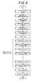
- FIG. 6 is a flowchart that explains an example of operation of the CPU in a conventional sensor module. It can be seen that the CPU sends a measuring command to the pressure sensor and waits until the pressure sensor is stabilized, before reading out the pressure data. Then, the CPU sends a measuring command to the temperature sensor, and waits until the temperature sensor is stabilized, before reading out the temperature data. Subsequently, the CPU converts the pressure data and the temperature data into a digital data, which is transmitted to the receiver on the vehicle body side. The CPU then wait until the transmission time interval elapses and transmits the digitized measured data to the receiver on the vehicle body side again.
- the CPU After repeating the transmission of the measured data by a desired number of times, the CPU terminates the transmission processing and is switched into a sleeping mode by lowering the clock frequency.
- the CPU is not switched into the sleeping mode and continues to consume unnecessary electric power.
- the present invention has been made in view of these problems of the prior art. It is an objection of the present invention to provide an improved an improved tire pressure information monitoring system allowing extension of the battery life by suppressing unnecessary electric power consumption in the waiting mode of the CPU.
- a tire pressure information monitoring system including a sensor for acquiring internal information of a tire, and operating with a low frequency clock and/or a high frequency clock; wherein the monitoring system operates with the high frequency clock, to transmit a command signal to the sensor to acquire the tire internal information; and wherein the monitoring system thereafter operates with the low frequency clock.
- a tire pressure information monitoring system including a sensor for acquiring internal information of a tire, and operating with a low frequency clock and/or a high frequency clock; wherein the monitoring system operates with the high frequency clock, to transmit the tire internal information acquired by the sensor to an external receiver means at a constant time interval; and wherein the monitoring system operates, after transmission of the tire internal information, with the low frequency clock until expiration of said time interval.
- the sensor is one of a pressure sensor and a temperature sensor.
- the CPU when the CPU is assuming a waiting mode essentially without performing any processing, it is switched into a sleeping mode to suppress unnecessary electric power consumption, thereby allowing extension of the battery life.
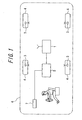
- FIG. 1 is a block diagram of a tire pressure monitoring system to which the sensor module (tire pressure measuring device) according to present invention is applied.
- the tire pressure monitoring system is mounted on a vehicle 6 as being secured to each wheel 4 of the vehicle 6, and includes a sensor module 3 for measuring the pressure or temperature within a tire of the wheel 4 and transmitting the measured pressure data or temperature data to the vehicle body side, a receiver 1 for receiving the pressure data or temperature data transmitted from an antenna of the sensor module 3 by wireless communication, a vehicle-mounted controller in the form of an electronic control unit (ECU) 5 for acquiring the pressure data or temperature data from the receiver 1 and judging abnormality of the pressure data or temperature data for each mounting position of the tire, and a display device 7 mounted in a driver's cabin and displaying, for each mounting position of the tire, that the pressure or temperature within the tire is abnormal when it has been so judged by the electronic control unit 5.
- ECU electronice control unit
- the sensor module 3 serves to acquire tire internal information, such as tire pressure or tire temperature, at a predetermined time interval, and to transmit the information to the receiver 1 on the vehicle body side by wireless communication. Further, the electronic control unit 5 stores a correspondence table which memorizes the correspondence between the tire mounting positions and identification codes unique to the sensor modules 3. The measured data signal transmitted from the sensor module 3 is added with a sensor identification code. Thus, by checking whether the transmitted identification code matches with that stored in the correspondence table, the electronic control unit 5 judges the position where the tire is mounted, and determines the tire for which a warning is to be issued.
- tire internal information such as tire pressure or tire temperature
- the sensor module 3 is secured to a wheel rim 13 as being integrated with a substantially cylindrical tire valve 12 for supplying air to a tire 11.
- the sensor module 3 may be secured to the inner surface of the tire 11 by baking so that it is prevented from separation from the tire or breakage upon deformation of the tire during running under a loaded condition.
- the sensor module 3 may be held in the interior space of the tire 11 by a separate holding means.
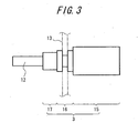
- FIG. 3 shows an example of the outer shape of the sensor module. It can be seen that the sensor module 3 includes a sensor module main body 15, a rim-mounting portion 16 and an antenna 17, and is secured to the wheel rim 13 as being integrated with the tire valve 12.
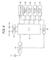
- the sensor module main body 15 includes an internal electric circuit device as shown by the schematic block diagram of FIG. 4 .
- This electric circuit device includes a pressure sensor 24 for detecting the air pressure within the tire, a temperature sensor 25 for detecting the temperature within the tire, a CPU 21 for performing signal processing and controlling the operation of the electric circuit device, a transmitter 22 for transmitting the signal from the CPU 21 to the receiver on the vehicle body side via the antenna 17, a first timer circuit 26 for counting the stabilizing time of the pressure sensor 24, a second timer circuit 27 for counting the stabilizing time of the temperature sensor 25, a third timer circuit 28 for counting the transmission time interval of the measured data to the receiver, a selector 23 for selecting either a low frequency clock or a high frequency clock for driving the CPU 21, and a battery 29 for supplying electric power to the components of the electric circuit device.
- the temperature sensor 25 serves to provide a warning to the driver based on more detailed information relating to the status of the tire internal space.
- the temperature sensor 25 is preferably included in the system, though it is not
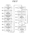
- FIG. 5 is a processing flowchart explaining the operation of the CPU 21.
- the CPU 21 operates with a high frequency clock to send a measuring command to the pressure sensor 24 (step 101).
- the CPU 21 causes the first timer circuit 26 to begin counting (step 102).
- the CPU 21 switches the selector 23 to the low frequency clock side and thereby selects the sleeping mode, i.e., the low power consumption mode (step 103).
- the first timer circuit 26 is set to a time required for stabilizing the measuring operation of the pressure sensor 24.
- the CPU 21 switches the selector 23 to the high frequency clock side so that the CPU operates with the high frequency clock to perform reading of the pressure information (pressure data) from the pressure sensor 24 (step 104).
- the CPU 21 then sends a measuring command to the temperature sensor 25 (step 105).
- the CPU 21 causes the second timer circuit 27 to begin counting (step 106).
- the CPU 21 switches the selector 23 to the low frequency clock side and thereby selects the sleeping mode, i.e., the low power consumption mode (step 107).
- the second timer circuit 27 is set to a time required for stabilizing the measuring operation of the temperature sensor 25.
- the CPU 21 switches the selector 23 to the high frequency clock side so that the CPU operates with the high frequency clock to perform reading of the temperature information (temperature data) from the temperature sensor 25 (step 108).
- the CPU 21 performs digital conversion of the acquired pressure information (pressure data) and the temperature information (temperature data) and adds an identification code unique to the sensor module 3 to generate a digital signal (step 109).
- the CPU initializes a counter i (not shown) (step 110) and transmits the digital signal including the pressure information (pressure data) and the temperature information (temperature data), from the transmitter 22 to the receiver on the vehicle body side, via the antenna 17 (step 111).
- the CPU 21 causes the third timer circuit 28 to count (step 112) and then switches the selector 23 to the low frequency clock side so that the CPU is switched to the sleeping mode (low power consumption mode) until a predetermined time interval elapses (step 113).
- the third timer circuit 28 is set to a time until a next transmission is performed (predetermined time interval).
- the CPU 21 then switches the selector 23 to the high frequency clock side and operates with the high frequency clock to transmit the digital signal including the pressure information (pressure data) and the temperature information (temperature data), from the transmitter 22 to the receiver on the vehicle body side, via the antenna 17 (step 111).
- the CPU 21 causes the third timer circuit 28 to count (step 112) and then switches the selector 23 to the low frequency clock side so that the CPU is switched to the sleeping mode (low power consumption mode) until a predetermined time interval elapses (step 113).
- the steps 111 to 114 are repeated a plurality of times (n times). If it is judged in step 115 that the counter i is not smaller than n, the CPU 21 switches the selector 23 to the high frequency clock side and operates with the high frequency clock to transmit the digital signal including the pressure information (pressure data) and the temperature information (temperature data), from the transmitter 22 to an external receiver via the antenna (step 116). Then, the CPU 21 switches the selector 23 to the low frequency clock side and thereby selects the sleeping mode (the low power consumption mode) to terminate the processing (step 117).
- the CPU 21 sends a measuring command to the pressure sensor 24 to acquire the pressure data, before sending a measuring command to the temperature sensor 25 to acquire the temperature data.
- the sequence may be reversed, i.e., the CPU 21 may send a measuring command to the temperature sensor 25 to acquire the temperature data, before sending a measuring command to the pressure sensor 24 to acquire the pressure data.
- the CPU 21 may send a measuring command to any one of the sensors to acquire the tire internal information.
- the CPU 21 may perform a series of processing (steps 101 to 104) for ends a measuring command to the pressure sensor 24 to acquire the pressure data for sending a measuring command to the pressure sensor 24 and acquiring the pressure data, and a series of processing sending a measuring command to the pressure sensor 24 and acquiring the pressure data, separately from each other.
- the acquired pressure data and temperature data may be stored in a memory within the sensor module main body 15, to perform the transmission processing following the step 111 at a predetermined time interval so as to transmit the measured data to the receiver on the vehicle body side.
Landscapes
- Engineering & Computer Science (AREA)
- Physics & Mathematics (AREA)
- General Physics & Mathematics (AREA)
- Mechanical Engineering (AREA)
- Computer Networks & Wireless Communication (AREA)
- Measuring Fluid Pressure (AREA)
- Arrangements For Transmission Of Measured Signals (AREA)
Abstract
Description
- The present invention relates to a tire pressure information monitoring system for measuring the internal pressure, etc., of a tire, and transmitting the acquired data to a receiver on a vehicle body side by wireless communication.
- There has been recently proposed to provide a vehicle with a tire pressure monitoring system (TPMS), as means for monitoring whether the air pressure filling a tire (internal pressure) is normal or abnormal. In this instance, a sensor module for measuring the internal pressure or internal temperature of the tire, etc., is provided inside the tire. The measured data is transmitted from the sensor module by wireless communication and received by a receiver on a vehicle body side, so that the received data is displayed by an on-board display device in a driver's cabin.
- In this type of tire pressure monitoring system, the sensor module provided within a tire is usually driven by battery. Thus, if the battery is exhausted and becomes unable to operate, it is impossible for the sensor module to transmit the measured data of the tire to the receiver on the vehicle body side. Therefore, it is highly desirable to suppress the electric power consumption of the battery for the sensor module as far as possible, and various proposals have been made to that end.
-
Patent Document 1 discloses a tire information acquisition system having a measuring/transmitting mode in which the measurement and data transmission are performed at a constant time interval, and a sleeping mode wherein the processing and transmission are halted. Also, Patent Document 2 discloses a tire pressure monitoring system that is switched into a low power consumption mode in a parking state of the vehicle. - [Patent Document 1]
JP 2004-314727A - [Patent Document 2]
JP 2004-322927A - As explained above, in conventional sensor modules, tire information (temperature and/or pressure) is periodically read out from the pressure sensor and/or temperature sensor, and converted into a digital wireless signal together with an identification code ID so as to be transmitted to the receiver on the vehicle body side. In this instance, the signal processing and/or control of the operation generally performed by an internal CPU that constitutes the sensor module. When a measuring command is transmitted from the CPU to the pressure sensor and/or temperature sensor, several microseconds are necessary until the pressure sensor and/or temperature sensor are stabilized. During such a period, the CPU assumes a waiting mode until the stabilizing time elapses, without lowering the clock frequency. Also, when transmitting the measured data to the receiver on the vehicle body side, the CPU performs transmission of the measured data to the receiver periodically at a constant transmission time interval. However, between the successive transmissions, the CPU assumes a waiting mode without lowering the clock frequency.
-
FIG. 6 is a flowchart that explains an example of operation of the CPU in a conventional sensor module. It can be seen that the CPU sends a measuring command to the pressure sensor and waits until the pressure sensor is stabilized, before reading out the pressure data. Then, the CPU sends a measuring command to the temperature sensor, and waits until the temperature sensor is stabilized, before reading out the temperature data. Subsequently, the CPU converts the pressure data and the temperature data into a digital data, which is transmitted to the receiver on the vehicle body side. The CPU then wait until the transmission time interval elapses and transmits the digitized measured data to the receiver on the vehicle body side again. After repeating the transmission of the measured data by a desired number of times, the CPU terminates the transmission processing and is switched into a sleeping mode by lowering the clock frequency. Thus, as explained above, there is a problem that, even during the waiting period of the CPU in which essentially no processing is performed, the CPU is not switched into the sleeping mode and continues to consume unnecessary electric power. - The present invention has been made in view of these problems of the prior art. It is an objection of the present invention to provide an improved an improved tire pressure information monitoring system allowing extension of the battery life by suppressing unnecessary electric power consumption in the waiting mode of the CPU.
- To achieve the above-mentioned object, according to one aspect of the present invention, there is provided a tire pressure information monitoring system including a sensor for acquiring internal information of a tire, and operating with a low frequency clock and/or a high frequency clock; wherein the monitoring system operates with the high frequency clock, to transmit a command signal to the sensor to acquire the tire internal information; and wherein the monitoring system thereafter operates with the low frequency clock. According to another aspect of the present invention, there is provided a tire pressure information monitoring system including a sensor for acquiring internal information of a tire, and operating with a low frequency clock and/or a high frequency clock; wherein the monitoring system operates with the high frequency clock, to transmit the tire internal information acquired by the sensor to an external receiver means at a constant time interval; and wherein the monitoring system operates, after transmission of the tire internal information, with the low frequency clock until expiration of said time interval. In either case, it is preferred that the sensor is one of a pressure sensor and a temperature sensor.
- According to the present invention, when the CPU is assuming a waiting mode essentially without performing any processing, it is switched into a sleeping mode to suppress unnecessary electric power consumption, thereby allowing extension of the battery life.
-
-
FIG. 1 is a block diagram of a tire pressure monitoring system to which the sensor module according to present invention is applied; -
FIG 2 is a sectional view showing an installation state of the sensor module to the vehicle wheel; -
FIG 3 is a view showing the outer shape of the sensor module; -
Fig. 4 is a schematic block diagram of the sensor module main body -
Fig. 5 is a processing flowchart explaining the operation of a CPU; and -
Fig. 6 is a processing flowchart explaining one example of the operation of a conventional CPU. -
- 1: Receiver
- 3: Sensor modules
- 4: Wheels
- 5: Electronic control unit (ECU)
- 6: Vehicle
- 7: Display device
- 11: Tire
- 12: Tire valve
- 13: Wheel rim
- 15: Sensor module main body
- 16: Rim mounting portion
- 17: Antenna
- 21: CPU
- 22: Transmitter
- 23: Selector
- 24: Pressure sensor
- 25: Temperature sensor
- 26: First timer circuit
- 27: Second timer circuit
- 28: Third timer circuit
- 29: Battery
- A preferred embodiment of the present invention will be explained below with reference to the drawings.
FIG. 1 is a block diagram of a tire pressure monitoring system to which the sensor module (tire pressure measuring device) according to present invention is applied. The tire pressure monitoring system is mounted on avehicle 6 as being secured to eachwheel 4 of thevehicle 6, and includes asensor module 3 for measuring the pressure or temperature within a tire of thewheel 4 and transmitting the measured pressure data or temperature data to the vehicle body side, areceiver 1 for receiving the pressure data or temperature data transmitted from an antenna of thesensor module 3 by wireless communication, a vehicle-mounted controller in the form of an electronic control unit (ECU) 5 for acquiring the pressure data or temperature data from thereceiver 1 and judging abnormality of the pressure data or temperature data for each mounting position of the tire, and a display device 7 mounted in a driver's cabin and displaying, for each mounting position of the tire, that the pressure or temperature within the tire is abnormal when it has been so judged by the electronic control unit 5. - The
sensor module 3 serves to acquire tire internal information, such as tire pressure or tire temperature, at a predetermined time interval, and to transmit the information to thereceiver 1 on the vehicle body side by wireless communication. Further, the electronic control unit 5 stores a correspondence table which memorizes the correspondence between the tire mounting positions and identification codes unique to thesensor modules 3. The measured data signal transmitted from thesensor module 3 is added with a sensor identification code. Thus, by checking whether the transmitted identification code matches with that stored in the correspondence table, the electronic control unit 5 judges the position where the tire is mounted, and determines the tire for which a warning is to be issued. - As can be appreciated from
FIG. 2 showing the sectional view of the wheel, thesensor module 3 is secured to awheel rim 13 as being integrated with a substantiallycylindrical tire valve 12 for supplying air to atire 11. Thesensor module 3 may be secured to the inner surface of thetire 11 by baking so that it is prevented from separation from the tire or breakage upon deformation of the tire during running under a loaded condition. Alternatively, thesensor module 3 may be held in the interior space of thetire 11 by a separate holding means. -
FIG. 3 shows an example of the outer shape of the sensor module. It can be seen that thesensor module 3 includes a sensor modulemain body 15, a rim-mountingportion 16 and anantenna 17, and is secured to thewheel rim 13 as being integrated with thetire valve 12. - The sensor module
main body 15 includes an internal electric circuit device as shown by the schematic block diagram ofFIG. 4 . This electric circuit device includes apressure sensor 24 for detecting the air pressure within the tire, atemperature sensor 25 for detecting the temperature within the tire, aCPU 21 for performing signal processing and controlling the operation of the electric circuit device, atransmitter 22 for transmitting the signal from theCPU 21 to the receiver on the vehicle body side via theantenna 17, afirst timer circuit 26 for counting the stabilizing time of thepressure sensor 24, asecond timer circuit 27 for counting the stabilizing time of thetemperature sensor 25, athird timer circuit 28 for counting the transmission time interval of the measured data to the receiver, aselector 23 for selecting either a low frequency clock or a high frequency clock for driving theCPU 21, and abattery 29 for supplying electric power to the components of the electric circuit device. Incidentally, thetemperature sensor 25 serves to provide a warning to the driver based on more detailed information relating to the status of the tire internal space. As such, thetemperature sensor 25 is preferably included in the system, though it is not necessarily an indispensable element. -
FIG. 5 is a processing flowchart explaining the operation of theCPU 21. When a predetermined timing is reached, theCPU 21 operates with a high frequency clock to send a measuring command to the pressure sensor 24 (step 101). After sending the measuring command to thepressure sensor 24, theCPU 21 causes thefirst timer circuit 26 to begin counting (step 102). Subsequently, theCPU 21 switches theselector 23 to the low frequency clock side and thereby selects the sleeping mode, i.e., the low power consumption mode (step 103). Thefirst timer circuit 26 is set to a time required for stabilizing the measuring operation of thepressure sensor 24. When the counting by thefirst timer circuit 26 is completed, theCPU 21 switches theselector 23 to the high frequency clock side so that the CPU operates with the high frequency clock to perform reading of the pressure information (pressure data) from the pressure sensor 24 (step 104). - The
CPU 21 then sends a measuring command to the temperature sensor 25 (step 105). After sending the measuring command to thetemperature sensor 25, theCPU 21 causes thesecond timer circuit 27 to begin counting (step 106). Subsequently, theCPU 21 switches theselector 23 to the low frequency clock side and thereby selects the sleeping mode, i.e., the low power consumption mode (step 107). Thesecond timer circuit 27 is set to a time required for stabilizing the measuring operation of thetemperature sensor 25. When the counting by thesecond timer circuit 27 is completed, theCPU 21 switches theselector 23 to the high frequency clock side so that the CPU operates with the high frequency clock to perform reading of the temperature information (temperature data) from the temperature sensor 25 (step 108). Then, theCPU 21 performs digital conversion of the acquired pressure information (pressure data) and the temperature information (temperature data) and adds an identification code unique to thesensor module 3 to generate a digital signal (step 109). - Subsequently, the CPU initializes a counter i (not shown) (step 110) and transmits the digital signal including the pressure information (pressure data) and the temperature information (temperature data), from the
transmitter 22 to the receiver on the vehicle body side, via the antenna 17 (step 111). When the digital signal has been transmitted, theCPU 21 causes thethird timer circuit 28 to count (step 112) and then switches theselector 23 to the low frequency clock side so that the CPU is switched to the sleeping mode (low power consumption mode) until a predetermined time interval elapses (step 113). Thethird timer circuit 28 is set to a time until a next transmission is performed (predetermined time interval). When the counting by thethird timer circuit 28 is completed, theCPU 21 increments the counter i and judges whether the incremented counter i is not smaller than n (e.g., n=10) (step 115). If the counter i is smaller than n, then the processing is returned to step 111. - The
CPU 21 then switches theselector 23 to the high frequency clock side and operates with the high frequency clock to transmit the digital signal including the pressure information (pressure data) and the temperature information (temperature data), from thetransmitter 22 to the receiver on the vehicle body side, via the antenna 17 (step 111). When the digital signal has been transmitted, theCPU 21 causes thethird timer circuit 28 to count (step 112) and then switches theselector 23 to the low frequency clock side so that the CPU is switched to the sleeping mode (low power consumption mode) until a predetermined time interval elapses (step 113). - In this way, the
steps 111 to 114 are repeated a plurality of times (n times). If it is judged instep 115 that the counter i is not smaller than n, theCPU 21 switches theselector 23 to the high frequency clock side and operates with the high frequency clock to transmit the digital signal including the pressure information (pressure data) and the temperature information (temperature data), from thetransmitter 22 to an external receiver via the antenna (step 116). Then, theCPU 21 switches theselector 23 to the low frequency clock side and thereby selects the sleeping mode (the low power consumption mode) to terminate the processing (step 117). - Incidentally, in the embodiment shown in
FIG. 5 , theCPU 21 sends a measuring command to thepressure sensor 24 to acquire the pressure data, before sending a measuring command to thetemperature sensor 25 to acquire the temperature data. However, the sequence may be reversed, i.e., theCPU 21 may send a measuring command to thetemperature sensor 25 to acquire the temperature data, before sending a measuring command to thepressure sensor 24 to acquire the pressure data. Also, theCPU 21 may send a measuring command to any one of the sensors to acquire the tire internal information. - Furthermore, the
CPU 21 may perform a series of processing (steps 101 to 104) for ends a measuring command to thepressure sensor 24 to acquire the pressure data for sending a measuring command to thepressure sensor 24 and acquiring the pressure data, and a series of processing sending a measuring command to thepressure sensor 24 and acquiring the pressure data, separately from each other. In this instance, the acquired pressure data and temperature data may be stored in a memory within the sensor modulemain body 15, to perform the transmission processing following thestep 111 at a predetermined time interval so as to transmit the measured data to the receiver on the vehicle body side. - It will be appreciated from the foregoing description that, according to the present invention, when the CPU assumes a waiting mode essentially without performing any processing, it is switched into a sleeping mode to suppress unnecessary electric power consumption, thereby allowing extension of the battery life.
Claims (4)
- A tire pressure information monitoring system including a sensor for acquiring internal information of a tire, and operating with a low frequency clock and/or a high frequency clock, wherein:said monitoring system operates with the high frequency clock, to transmit a command signal to the sensor to acquire the tire internal information; andsaid monitoring system thereafter operates with the low frequency clock.
- The tire pressure information monitoring system according to claim 1, wherein the sensor is one of a pressure sensor and a temperature sensor.
- A tire pressure information monitoring system including a sensor for acquiring internal information of a tire, and operating with a low frequency clock and/or a high frequency clock, wherein;said monitoring system operates with the high frequency clock, to transmit the tire internal information acquired by the sensor to an external receiver means at a constant time interval; andsaid monitoring system operates, after transmission of the tire internal information, with the low frequency clock until expiration of said time interval.
- The tire pressure information monitoring system according to claim 3, wherein the sensor is one of a pressure sensor and a temperature sensor.
Applications Claiming Priority (2)
| Application Number | Priority Date | Filing Date | Title |
|---|---|---|---|
| JP2007122744A JP5193495B2 (en) | 2007-05-07 | 2007-05-07 | Tire pressure information measuring device |
| PCT/JP2008/058498 WO2008140003A1 (en) | 2007-05-07 | 2008-05-07 | Tire inflation pressure measuring device |
Publications (3)
| Publication Number | Publication Date |
|---|---|
| EP2145778A1 true EP2145778A1 (en) | 2010-01-20 |
| EP2145778A4 EP2145778A4 (en) | 2012-10-24 |
| EP2145778B1 EP2145778B1 (en) | 2014-07-09 |
Family
ID=40002203
Family Applications (1)
| Application Number | Title | Priority Date | Filing Date |
|---|---|---|---|
| EP08752390.8A Not-in-force EP2145778B1 (en) | 2007-05-07 | 2008-05-07 | Tire inflation pressure measuring device |
Country Status (9)
| Country | Link |
|---|---|
| US (1) | US8266954B2 (en) |
| EP (1) | EP2145778B1 (en) |
| JP (1) | JP5193495B2 (en) |
| CN (1) | CN101678727B (en) |
| AU (1) | AU2008250181B2 (en) |
| BR (1) | BRPI0811555A2 (en) |
| CA (1) | CA2686090A1 (en) |
| ES (1) | ES2496170T3 (en) |
| WO (1) | WO2008140003A1 (en) |
Families Citing this family (6)
| Publication number | Priority date | Publication date | Assignee | Title |
|---|---|---|---|---|
| CN102529611A (en) * | 2011-12-22 | 2012-07-04 | 深圳市元征软件开发有限公司 | Electronic control unit (ECU) active control method of passive direct tire pressure monitor system (TPMS) |
| ES2752230T3 (en) * | 2013-03-11 | 2020-04-03 | Kapsch Trafficcom Ab | A method of communication within a cooperative system |
| CN103818204A (en) * | 2014-03-06 | 2014-05-28 | 深圳市道通科技有限公司 | Method and device for tire pressure monitoring |
| US11679632B2 (en) * | 2017-01-17 | 2023-06-20 | Autel Hechuang Software Development Co., Ltd. | Tire pressure sensor identification method and related apparatus and system |
| JP7293175B2 (en) * | 2020-09-09 | 2023-06-19 | 株式会社東芝 | Communication device |
| CN112319146B (en) * | 2020-10-16 | 2022-10-11 | 深圳市云伽智能技术有限公司 | Learning method, device, sensor, system and medium of tire pressure monitoring system |
Family Cites Families (16)
| Publication number | Priority date | Publication date | Assignee | Title |
|---|---|---|---|---|
| JPH10504783A (en) | 1994-08-31 | 1998-05-12 | オター コントロールズ リミテッド | Tire condition monitoring system |
| US6710708B2 (en) * | 1999-02-05 | 2004-03-23 | Schrader-Bridgeport International, Inc. | Method and apparatus for a remote tire pressure monitoring system |
| US7161476B2 (en) * | 2000-07-26 | 2007-01-09 | Bridgestone Firestone North American Tire, Llc | Electronic tire management system |
| EP2272688B1 (en) | 2000-07-26 | 2012-02-01 | Bridgestone Americas Tire Operations, LLC | Electronic tire management system |
| JP2002291077A (en) * | 2001-03-28 | 2002-10-04 | Denso Corp | Wireless controller |
| US6829924B2 (en) * | 2002-03-01 | 2004-12-14 | Lear Corporation | Tire pressure monitoring system with low frequency initiation approach |
| JP2003314727A (en) | 2002-04-23 | 2003-11-06 | Toyoda Mach Works Ltd | Solenoid valve |
| JP3637035B2 (en) * | 2002-06-07 | 2005-04-06 | 三菱電機株式会社 | In-vehicle device remote control device |
| JP4007905B2 (en) * | 2002-12-10 | 2007-11-14 | アルプス電気株式会社 | Passive keyless entry device for monitoring tire pressure with two-way communication |
| JP4152240B2 (en) * | 2003-04-14 | 2008-09-17 | 横浜ゴム株式会社 | Wheel information acquisition system |
| JP4008379B2 (en) | 2003-04-25 | 2007-11-14 | 矢崎総業株式会社 | Tire pressure monitoring system |
| CN1278881C (en) * | 2003-09-03 | 2006-10-11 | 上海泰好电子科技有限公司 | Tyre monitoring sensor |
| JP2005329856A (en) * | 2004-05-21 | 2005-12-02 | Nec Electronics Corp | Monitoring device, transceiving system and its control method |
| JP3953474B2 (en) * | 2004-06-18 | 2007-08-08 | Necエレクトロニクス株式会社 | Control device, tire pressure monitoring control device, control method, and tire pressure monitoring control method |
| US7132939B2 (en) * | 2004-07-07 | 2006-11-07 | Michelin Recherche Et Technique S.A. | Integrated self-powered tire revolution counter |
| CN1730303A (en) * | 2005-08-29 | 2006-02-08 | 浙江大学 | Tire air pressure monitoring modular |
-
2007
- 2007-05-07 JP JP2007122744A patent/JP5193495B2/en not_active Expired - Fee Related
-
2008
- 2008-05-07 BR BRPI0811555-9A2A patent/BRPI0811555A2/en not_active Application Discontinuation
- 2008-05-07 AU AU2008250181A patent/AU2008250181B2/en not_active Ceased
- 2008-05-07 EP EP08752390.8A patent/EP2145778B1/en not_active Not-in-force
- 2008-05-07 WO PCT/JP2008/058498 patent/WO2008140003A1/en not_active Ceased
- 2008-05-07 ES ES08752390.8T patent/ES2496170T3/en active Active
- 2008-05-07 CN CN2008800152810A patent/CN101678727B/en not_active Expired - Fee Related
- 2008-05-07 CA CA002686090A patent/CA2686090A1/en not_active Abandoned
- 2008-05-07 US US12/598,851 patent/US8266954B2/en not_active Expired - Fee Related
Also Published As
| Publication number | Publication date |
|---|---|
| US20100089140A1 (en) | 2010-04-15 |
| CN101678727A (en) | 2010-03-24 |
| ES2496170T3 (en) | 2014-09-18 |
| JP2008273484A (en) | 2008-11-13 |
| AU2008250181B2 (en) | 2011-03-17 |
| EP2145778B1 (en) | 2014-07-09 |
| EP2145778A4 (en) | 2012-10-24 |
| CN101678727B (en) | 2012-05-30 |
| CA2686090A1 (en) | 2008-11-20 |
| AU2008250181A1 (en) | 2008-11-20 |
| BRPI0811555A2 (en) | 2014-12-09 |
| WO2008140003A1 (en) | 2008-11-20 |
| US8266954B2 (en) | 2012-09-18 |
| JP5193495B2 (en) | 2013-05-08 |
Similar Documents
| Publication | Publication Date | Title |
|---|---|---|
| US6938467B2 (en) | Transmitter of tire condition monitoring apparatus | |
| EP2145778B1 (en) | Tire inflation pressure measuring device | |
| KR100839165B1 (en) | Vehicle wheel information processing device and method | |
| US7701326B2 (en) | Tire information transmitter and tire information acquisition system using the transmitter | |
| US20050258949A1 (en) | Monitoring device, transceiver system and its control method | |
| US6954688B2 (en) | Tire status monitoring apparatus | |
| CN102015336B (en) | Methods, systems and system components for wireless tire pressure monitoring | |
| EP1452348A1 (en) | Tire condition monitoring with temperature dependent transmission times for reception probability | |
| US8560159B2 (en) | Method, system and system components for wireless tire pressure monitoring | |
| EP2562012A1 (en) | Valve ID registration system | |
| US7667584B2 (en) | Tire administration system | |
| AU2005254356B2 (en) | Tire management system | |
| US8026803B2 (en) | Apparatus and process for monitoring a vehicle condition | |
| US6817237B2 (en) | Tire condition monitoring apparatus | |
| JP4778729B2 (en) | Tire management system | |
| EP1924448B1 (en) | Tyre pressure monitoring system | |
| US8296006B2 (en) | Tire pressure monitoring device | |
| WO2007145252A1 (en) | Tire information acquisition system | |
| JP2007331604A (en) | Tire pneumatic pressure monitoring system | |
| JP2007331586A (en) | Tire pneumatic pressure monitoring device |
Legal Events
| Date | Code | Title | Description |
|---|---|---|---|
| PUAI | Public reference made under article 153(3) epc to a published international application that has entered the european phase |
Free format text: ORIGINAL CODE: 0009012 |
|
| 17P | Request for examination filed |
Effective date: 20091113 |
|
| AK | Designated contracting states |
Kind code of ref document: A1 Designated state(s): AT BE BG CH CY CZ DE DK EE ES FI FR GB GR HR HU IE IS IT LI LT LU LV MC MT NL NO PL PT RO SE SI SK TR |
|
| AX | Request for extension of the european patent |
Extension state: AL BA MK RS |
|
| DAX | Request for extension of the european patent (deleted) | ||
| A4 | Supplementary search report drawn up and despatched |
Effective date: 20120921 |
|
| RIC1 | Information provided on ipc code assigned before grant |
Ipc: G01L 17/00 20060101ALI20120917BHEP Ipc: B60C 23/20 20060101ALI20120917BHEP Ipc: B60C 23/04 20060101AFI20120917BHEP |
|
| GRAP | Despatch of communication of intention to grant a patent |
Free format text: ORIGINAL CODE: EPIDOSNIGR1 |
|
| INTG | Intention to grant announced |
Effective date: 20130628 |
|
| GRAP | Despatch of communication of intention to grant a patent |
Free format text: ORIGINAL CODE: EPIDOSNIGR1 |
|
| INTG | Intention to grant announced |
Effective date: 20140117 |
|
| GRAS | Grant fee paid |
Free format text: ORIGINAL CODE: EPIDOSNIGR3 |
|
| GRAA | (expected) grant |
Free format text: ORIGINAL CODE: 0009210 |
|
| AK | Designated contracting states |
Kind code of ref document: B1 Designated state(s): AT BE BG CH CY CZ DE DK EE ES FI FR GB GR HR HU IE IS IT LI LT LU LV MC MT NL NO PL PT RO SE SI SK TR |
|
| REG | Reference to a national code |
Ref country code: GB Ref legal event code: FG4D |
|
| REG | Reference to a national code |
Ref country code: AT Ref legal event code: REF Ref document number: 676437 Country of ref document: AT Kind code of ref document: T Effective date: 20140715 Ref country code: CH Ref legal event code: EP |
|
| REG | Reference to a national code |
Ref country code: IE Ref legal event code: FG4D |
|
| REG | Reference to a national code |
Ref country code: DE Ref legal event code: R096 Ref document number: 602008033209 Country of ref document: DE Effective date: 20140821 |
|
| REG | Reference to a national code |
Ref country code: ES Ref legal event code: FG2A Ref document number: 2496170 Country of ref document: ES Kind code of ref document: T3 Effective date: 20140918 |
|
| REG | Reference to a national code |
Ref country code: AT Ref legal event code: MK05 Ref document number: 676437 Country of ref document: AT Kind code of ref document: T Effective date: 20140709 |
|
| REG | Reference to a national code |
Ref country code: NL Ref legal event code: VDEP Effective date: 20140709 |
|
| REG | Reference to a national code |
Ref country code: LT Ref legal event code: MG4D |
|
| PG25 | Lapsed in a contracting state [announced via postgrant information from national office to epo] |
Ref country code: GR Free format text: LAPSE BECAUSE OF FAILURE TO SUBMIT A TRANSLATION OF THE DESCRIPTION OR TO PAY THE FEE WITHIN THE PRESCRIBED TIME-LIMIT Effective date: 20141010 Ref country code: BG Free format text: LAPSE BECAUSE OF FAILURE TO SUBMIT A TRANSLATION OF THE DESCRIPTION OR TO PAY THE FEE WITHIN THE PRESCRIBED TIME-LIMIT Effective date: 20141009 Ref country code: SE Free format text: LAPSE BECAUSE OF FAILURE TO SUBMIT A TRANSLATION OF THE DESCRIPTION OR TO PAY THE FEE WITHIN THE PRESCRIBED TIME-LIMIT Effective date: 20140709 Ref country code: NO Free format text: LAPSE BECAUSE OF FAILURE TO SUBMIT A TRANSLATION OF THE DESCRIPTION OR TO PAY THE FEE WITHIN THE PRESCRIBED TIME-LIMIT Effective date: 20141009 Ref country code: PT Free format text: LAPSE BECAUSE OF FAILURE TO SUBMIT A TRANSLATION OF THE DESCRIPTION OR TO PAY THE FEE WITHIN THE PRESCRIBED TIME-LIMIT Effective date: 20141110 Ref country code: LT Free format text: LAPSE BECAUSE OF FAILURE TO SUBMIT A TRANSLATION OF THE DESCRIPTION OR TO PAY THE FEE WITHIN THE PRESCRIBED TIME-LIMIT Effective date: 20140709 Ref country code: FI Free format text: LAPSE BECAUSE OF FAILURE TO SUBMIT A TRANSLATION OF THE DESCRIPTION OR TO PAY THE FEE WITHIN THE PRESCRIBED TIME-LIMIT Effective date: 20140709 |
|
| PG25 | Lapsed in a contracting state [announced via postgrant information from national office to epo] |
Ref country code: PL Free format text: LAPSE BECAUSE OF FAILURE TO SUBMIT A TRANSLATION OF THE DESCRIPTION OR TO PAY THE FEE WITHIN THE PRESCRIBED TIME-LIMIT Effective date: 20140709 Ref country code: HR Free format text: LAPSE BECAUSE OF FAILURE TO SUBMIT A TRANSLATION OF THE DESCRIPTION OR TO PAY THE FEE WITHIN THE PRESCRIBED TIME-LIMIT Effective date: 20140709 Ref country code: CY Free format text: LAPSE BECAUSE OF FAILURE TO SUBMIT A TRANSLATION OF THE DESCRIPTION OR TO PAY THE FEE WITHIN THE PRESCRIBED TIME-LIMIT Effective date: 20140709 Ref country code: AT Free format text: LAPSE BECAUSE OF FAILURE TO SUBMIT A TRANSLATION OF THE DESCRIPTION OR TO PAY THE FEE WITHIN THE PRESCRIBED TIME-LIMIT Effective date: 20140709 Ref country code: NL Free format text: LAPSE BECAUSE OF FAILURE TO SUBMIT A TRANSLATION OF THE DESCRIPTION OR TO PAY THE FEE WITHIN THE PRESCRIBED TIME-LIMIT Effective date: 20140709 Ref country code: LV Free format text: LAPSE BECAUSE OF FAILURE TO SUBMIT A TRANSLATION OF THE DESCRIPTION OR TO PAY THE FEE WITHIN THE PRESCRIBED TIME-LIMIT Effective date: 20140709 Ref country code: IS Free format text: LAPSE BECAUSE OF FAILURE TO SUBMIT A TRANSLATION OF THE DESCRIPTION OR TO PAY THE FEE WITHIN THE PRESCRIBED TIME-LIMIT Effective date: 20141109 |
|
| REG | Reference to a national code |
Ref country code: DE Ref legal event code: R097 Ref document number: 602008033209 Country of ref document: DE |
|
| PG25 | Lapsed in a contracting state [announced via postgrant information from national office to epo] |
Ref country code: DK Free format text: LAPSE BECAUSE OF FAILURE TO SUBMIT A TRANSLATION OF THE DESCRIPTION OR TO PAY THE FEE WITHIN THE PRESCRIBED TIME-LIMIT Effective date: 20140709 Ref country code: RO Free format text: LAPSE BECAUSE OF FAILURE TO SUBMIT A TRANSLATION OF THE DESCRIPTION OR TO PAY THE FEE WITHIN THE PRESCRIBED TIME-LIMIT Effective date: 20140709 Ref country code: SK Free format text: LAPSE BECAUSE OF FAILURE TO SUBMIT A TRANSLATION OF THE DESCRIPTION OR TO PAY THE FEE WITHIN THE PRESCRIBED TIME-LIMIT Effective date: 20140709 Ref country code: CZ Free format text: LAPSE BECAUSE OF FAILURE TO SUBMIT A TRANSLATION OF THE DESCRIPTION OR TO PAY THE FEE WITHIN THE PRESCRIBED TIME-LIMIT Effective date: 20140709 Ref country code: EE Free format text: LAPSE BECAUSE OF FAILURE TO SUBMIT A TRANSLATION OF THE DESCRIPTION OR TO PAY THE FEE WITHIN THE PRESCRIBED TIME-LIMIT Effective date: 20140709 |
|
| PLBE | No opposition filed within time limit |
Free format text: ORIGINAL CODE: 0009261 |
|
| STAA | Information on the status of an ep patent application or granted ep patent |
Free format text: STATUS: NO OPPOSITION FILED WITHIN TIME LIMIT |
|
| 26N | No opposition filed |
Effective date: 20150410 |
|
| PG25 | Lapsed in a contracting state [announced via postgrant information from national office to epo] |
Ref country code: SI Free format text: LAPSE BECAUSE OF FAILURE TO SUBMIT A TRANSLATION OF THE DESCRIPTION OR TO PAY THE FEE WITHIN THE PRESCRIBED TIME-LIMIT Effective date: 20140709 |
|
| REG | Reference to a national code |
Ref country code: CH Ref legal event code: PL |
|
| PG25 | Lapsed in a contracting state [announced via postgrant information from national office to epo] |
Ref country code: CH Free format text: LAPSE BECAUSE OF NON-PAYMENT OF DUE FEES Effective date: 20150531 Ref country code: MC Free format text: LAPSE BECAUSE OF FAILURE TO SUBMIT A TRANSLATION OF THE DESCRIPTION OR TO PAY THE FEE WITHIN THE PRESCRIBED TIME-LIMIT Effective date: 20140709 Ref country code: LU Free format text: LAPSE BECAUSE OF FAILURE TO SUBMIT A TRANSLATION OF THE DESCRIPTION OR TO PAY THE FEE WITHIN THE PRESCRIBED TIME-LIMIT Effective date: 20150507 Ref country code: LI Free format text: LAPSE BECAUSE OF NON-PAYMENT OF DUE FEES Effective date: 20150531 |
|
| REG | Reference to a national code |
Ref country code: IE Ref legal event code: MM4A |
|
| PG25 | Lapsed in a contracting state [announced via postgrant information from national office to epo] |
Ref country code: IE Free format text: LAPSE BECAUSE OF NON-PAYMENT OF DUE FEES Effective date: 20150507 |
|
| REG | Reference to a national code |
Ref country code: FR Ref legal event code: PLFP Year of fee payment: 9 |
|
| PG25 | Lapsed in a contracting state [announced via postgrant information from national office to epo] |
Ref country code: BE Free format text: LAPSE BECAUSE OF FAILURE TO SUBMIT A TRANSLATION OF THE DESCRIPTION OR TO PAY THE FEE WITHIN THE PRESCRIBED TIME-LIMIT Effective date: 20140709 |
|
| PGFP | Annual fee paid to national office [announced via postgrant information from national office to epo] |
Ref country code: GB Payment date: 20160520 Year of fee payment: 9 Ref country code: ES Payment date: 20160512 Year of fee payment: 9 |
|
| PGFP | Annual fee paid to national office [announced via postgrant information from national office to epo] |
Ref country code: IT Payment date: 20160524 Year of fee payment: 9 |
|
| PG25 | Lapsed in a contracting state [announced via postgrant information from national office to epo] |
Ref country code: MT Free format text: LAPSE BECAUSE OF FAILURE TO SUBMIT A TRANSLATION OF THE DESCRIPTION OR TO PAY THE FEE WITHIN THE PRESCRIBED TIME-LIMIT Effective date: 20140709 |
|
| REG | Reference to a national code |
Ref country code: FR Ref legal event code: PLFP Year of fee payment: 10 |
|
| PG25 | Lapsed in a contracting state [announced via postgrant information from national office to epo] |
Ref country code: HU Free format text: LAPSE BECAUSE OF FAILURE TO SUBMIT A TRANSLATION OF THE DESCRIPTION OR TO PAY THE FEE WITHIN THE PRESCRIBED TIME-LIMIT; INVALID AB INITIO Effective date: 20080507 |
|
| PG25 | Lapsed in a contracting state [announced via postgrant information from national office to epo] |
Ref country code: TR Free format text: LAPSE BECAUSE OF FAILURE TO SUBMIT A TRANSLATION OF THE DESCRIPTION OR TO PAY THE FEE WITHIN THE PRESCRIBED TIME-LIMIT Effective date: 20140709 |
|
| GBPC | Gb: european patent ceased through non-payment of renewal fee |
Effective date: 20170507 |
|
| PG25 | Lapsed in a contracting state [announced via postgrant information from national office to epo] |
Ref country code: GB Free format text: LAPSE BECAUSE OF NON-PAYMENT OF DUE FEES Effective date: 20170507 |
|
| REG | Reference to a national code |
Ref country code: FR Ref legal event code: PLFP Year of fee payment: 11 |
|
| PG25 | Lapsed in a contracting state [announced via postgrant information from national office to epo] |
Ref country code: IT Free format text: LAPSE BECAUSE OF NON-PAYMENT OF DUE FEES Effective date: 20170507 |
|
| REG | Reference to a national code |
Ref country code: ES Ref legal event code: FD2A Effective date: 20180706 |
|
| PG25 | Lapsed in a contracting state [announced via postgrant information from national office to epo] |
Ref country code: ES Free format text: LAPSE BECAUSE OF NON-PAYMENT OF DUE FEES Effective date: 20170508 |
|
| PGFP | Annual fee paid to national office [announced via postgrant information from national office to epo] |
Ref country code: DE Payment date: 20190521 Year of fee payment: 12 |
|
| PGFP | Annual fee paid to national office [announced via postgrant information from national office to epo] |
Ref country code: FR Payment date: 20190523 Year of fee payment: 12 |
|
| REG | Reference to a national code |
Ref country code: DE Ref legal event code: R119 Ref document number: 602008033209 Country of ref document: DE |
|
| PG25 | Lapsed in a contracting state [announced via postgrant information from national office to epo] |
Ref country code: FR Free format text: LAPSE BECAUSE OF NON-PAYMENT OF DUE FEES Effective date: 20200531 |
|
| PG25 | Lapsed in a contracting state [announced via postgrant information from national office to epo] |
Ref country code: DE Free format text: LAPSE BECAUSE OF NON-PAYMENT OF DUE FEES Effective date: 20201201 |