EP2145097B1 - Waterproof connecting structure for pipe - Google Patents
Waterproof connecting structure for pipe Download PDFInfo
- Publication number
- EP2145097B1 EP2145097B1 EP08777424A EP08777424A EP2145097B1 EP 2145097 B1 EP2145097 B1 EP 2145097B1 EP 08777424 A EP08777424 A EP 08777424A EP 08777424 A EP08777424 A EP 08777424A EP 2145097 B1 EP2145097 B1 EP 2145097B1
- Authority
- EP
- European Patent Office
- Prior art keywords
- hole
- pipe
- partition wall
- space
- connecting space
- Prior art date
- Legal status (The legal status is an assumption and is not a legal conclusion. Google has not performed a legal analysis and makes no representation as to the accuracy of the status listed.)
- Not-in-force
Links
- 238000005192 partition Methods 0.000 claims abstract description 62
- 238000002485 combustion reaction Methods 0.000 claims abstract description 9
- 239000012530 fluid Substances 0.000 claims abstract 2
- XLYOFNOQVPJJNP-UHFFFAOYSA-N water Substances O XLYOFNOQVPJJNP-UHFFFAOYSA-N 0.000 description 90
- 239000012528 membrane Substances 0.000 description 14
- 238000004078 waterproofing Methods 0.000 description 8
- 230000000694 effects Effects 0.000 description 6
- 238000001514 detection method Methods 0.000 description 5
- 239000012141 concentrate Substances 0.000 description 4
- 230000002093 peripheral effect Effects 0.000 description 4
- 230000000052 comparative effect Effects 0.000 description 3
- 239000000126 substance Substances 0.000 description 3
- 230000009977 dual effect Effects 0.000 description 2
- 230000009545 invasion Effects 0.000 description 2
- 230000004323 axial length Effects 0.000 description 1
- 230000001771 impaired effect Effects 0.000 description 1
- 239000002184 metal Substances 0.000 description 1
- 238000000034 method Methods 0.000 description 1
- 238000003466 welding Methods 0.000 description 1
Images



Classifications
-
- F—MECHANICAL ENGINEERING; LIGHTING; HEATING; WEAPONS; BLASTING
- F02—COMBUSTION ENGINES; HOT-GAS OR COMBUSTION-PRODUCT ENGINE PLANTS
- F02M—SUPPLYING COMBUSTION ENGINES IN GENERAL WITH COMBUSTIBLE MIXTURES OR CONSTITUENTS THEREOF
- F02M35/00—Combustion-air cleaners, air intakes, intake silencers, or induction systems specially adapted for, or arranged on, internal-combustion engines
- F02M35/10—Air intakes; Induction systems
- F02M35/10242—Devices or means connected to or integrated into air intakes; Air intakes combined with other engine or vehicle parts
- F02M35/10249—Electrical or electronic devices fixed to the intake system; Electric wiring
-
- F—MECHANICAL ENGINEERING; LIGHTING; HEATING; WEAPONS; BLASTING
- F02—COMBUSTION ENGINES; HOT-GAS OR COMBUSTION-PRODUCT ENGINE PLANTS
- F02M—SUPPLYING COMBUSTION ENGINES IN GENERAL WITH COMBUSTIBLE MIXTURES OR CONSTITUENTS THEREOF
- F02M35/00—Combustion-air cleaners, air intakes, intake silencers, or induction systems specially adapted for, or arranged on, internal-combustion engines
- F02M35/10—Air intakes; Induction systems
- F02M35/10006—Air intakes; Induction systems characterised by the position of elements of the air intake system in direction of the air intake flow, i.e. between ambient air inlet and supply to the combustion chamber
- F02M35/10026—Plenum chambers
- F02M35/10039—Intake ducts situated partly within or on the plenum chamber housing
-
- F—MECHANICAL ENGINEERING; LIGHTING; HEATING; WEAPONS; BLASTING
- F02—COMBUSTION ENGINES; HOT-GAS OR COMBUSTION-PRODUCT ENGINE PLANTS
- F02M—SUPPLYING COMBUSTION ENGINES IN GENERAL WITH COMBUSTIBLE MIXTURES OR CONSTITUENTS THEREOF
- F02M35/00—Combustion-air cleaners, air intakes, intake silencers, or induction systems specially adapted for, or arranged on, internal-combustion engines
- F02M35/10—Air intakes; Induction systems
- F02M35/10091—Air intakes; Induction systems characterised by details of intake ducts: shapes; connections; arrangements
- F02M35/10124—Ducts with special cross-sections, e.g. non-circular cross-section
-
- F—MECHANICAL ENGINEERING; LIGHTING; HEATING; WEAPONS; BLASTING
- F02—COMBUSTION ENGINES; HOT-GAS OR COMBUSTION-PRODUCT ENGINE PLANTS
- F02M—SUPPLYING COMBUSTION ENGINES IN GENERAL WITH COMBUSTIBLE MIXTURES OR CONSTITUENTS THEREOF
- F02M35/00—Combustion-air cleaners, air intakes, intake silencers, or induction systems specially adapted for, or arranged on, internal-combustion engines
- F02M35/10—Air intakes; Induction systems
- F02M35/10091—Air intakes; Induction systems characterised by details of intake ducts: shapes; connections; arrangements
- F02M35/10144—Connections of intake ducts to each other or to another device
-
- F—MECHANICAL ENGINEERING; LIGHTING; HEATING; WEAPONS; BLASTING
- F02—COMBUSTION ENGINES; HOT-GAS OR COMBUSTION-PRODUCT ENGINE PLANTS
- F02M—SUPPLYING COMBUSTION ENGINES IN GENERAL WITH COMBUSTIBLE MIXTURES OR CONSTITUENTS THEREOF
- F02M35/00—Combustion-air cleaners, air intakes, intake silencers, or induction systems specially adapted for, or arranged on, internal-combustion engines
- F02M35/10—Air intakes; Induction systems
- F02M35/10373—Sensors for intake systems
- F02M35/1038—Sensors for intake systems for temperature or pressure
-
- G—PHYSICS
- G01—MEASURING; TESTING
- G01L—MEASURING FORCE, STRESS, TORQUE, WORK, MECHANICAL POWER, MECHANICAL EFFICIENCY, OR FLUID PRESSURE
- G01L23/00—Devices or apparatus for measuring or indicating or recording rapid changes, such as oscillations, in the pressure of steam, gas, or liquid; Indicators for determining work or energy of steam, internal-combustion, or other fluid-pressure engines from the condition of the working fluid
- G01L23/24—Devices or apparatus for measuring or indicating or recording rapid changes, such as oscillations, in the pressure of steam, gas, or liquid; Indicators for determining work or energy of steam, internal-combustion, or other fluid-pressure engines from the condition of the working fluid specially adapted for measuring pressure in inlet or exhaust ducts of internal-combustion engines
-
- F—MECHANICAL ENGINEERING; LIGHTING; HEATING; WEAPONS; BLASTING
- F02—COMBUSTION ENGINES; HOT-GAS OR COMBUSTION-PRODUCT ENGINE PLANTS
- F02M—SUPPLYING COMBUSTION ENGINES IN GENERAL WITH COMBUSTIBLE MIXTURES OR CONSTITUENTS THEREOF
- F02M35/00—Combustion-air cleaners, air intakes, intake silencers, or induction systems specially adapted for, or arranged on, internal-combustion engines
- F02M35/02—Air cleaners
-
- Y—GENERAL TAGGING OF NEW TECHNOLOGICAL DEVELOPMENTS; GENERAL TAGGING OF CROSS-SECTIONAL TECHNOLOGIES SPANNING OVER SEVERAL SECTIONS OF THE IPC; TECHNICAL SUBJECTS COVERED BY FORMER USPC CROSS-REFERENCE ART COLLECTIONS [XRACs] AND DIGESTS
- Y02—TECHNOLOGIES OR APPLICATIONS FOR MITIGATION OR ADAPTATION AGAINST CLIMATE CHANGE
- Y02T—CLIMATE CHANGE MITIGATION TECHNOLOGIES RELATED TO TRANSPORTATION
- Y02T10/00—Road transport of goods or passengers
- Y02T10/10—Internal combustion engine [ICE] based vehicles
- Y02T10/12—Improving ICE efficiencies
Definitions
- the present invention relates to a waterproof connecting structure for a pipe for connecting an intake passage of an internal combustion engine to an external gas detector so as to convey gas from the intake passage.
- a suction pressure sensor is sometimes provided in an internal combustion engine to control the internal combustion engine.
- a pipe is disposed between the suction pressure sensor and an intake passage such as a surge tank, as described in Japanese Laid-Open Patent Publication 2000-88688 and Japanese Laid-Open Patent Publication 9-68066 .
- water droplets generated in the surge tank may attach to a hole formed in the pipe.
- the water droplets may pass through the hole and enter a gas filter provided within the pipe or even enter the suction pressure sensor, preventing high-accuracy detection by the suction pressure sensor.
- the water droplets that enter the pipe may freeze in a cold region thereby causing the pipe, the gas filter, or the suction pressure sensor to break
- Japanese Laid-Open Patent Publication 2000-88688 discloses an annular thickened portion around a hole of a pipe to prevent water from entering the pipe by keeping water droplets that move along the wall surface of the surge tank away from the hole of the pipe.
- Japanese Laid-Open Patent Publication 9-68066 discloses an elongate cylinder extending around a hole of a pipe and another cylinder, wherein the structure of the dual cylinders prevents water from entering the pipe.
- the structure of this document can stop water droplets that drift in through intake air.
- the inner cylinder of the dual cylinders is provided on the wall surface on which a hole of the pipe is provided while an outer cylinder is provided on the wall surface opposite to the pipe hole.
- This configuration makes the intake passage such as a surge tank complicated and locations to provide such a waterproof structure are limited, which extremely reduces the degree of freedom for location of the pipe.
- US 6,604,424 describes a pressure detecting apparatus having a pressure introducing pipe installed on an intake surge tank for detecting inner pressure in the intake surge tank.
- the intake surge tank is provided with a throttle passage having a throttle is disposed in the intake surge tank along a flow direction of the gas for increasing a flow speed of the gas.
- a pressure inlet at a leading end of the pressure introducing pipe is positioned in a vicinity of the throttle.
- JP 11159367A aims to prevent the invasion of a dirty substance such as oil or the like into a pressure detecting device in a path for transmitting pressure in an intake tube for an internal combustion engine.
- a pressure detection device is provided on a throttle body
- plural chambers are arranged between the throttle body and the pressure detection device; comparatively narrow paths communicate with the same to as to forma series of paths for pressure transmitting as a whole.
- the plural paths communicating with arbitrary one chamber are alternately arranged so as not to be on one straight line mutually. Since air flow containing a dirty substance such as oil revolves along wall faces in the chambers, the dirty substance is stuck onto the wall faces and is efficiently captured so that the invasion into the pressure detection device can be surely prevented.
- An object of the present invention is to provide waterproof connecting structure for use in a pipe that can prevent intrusion of droplets moving along a wall surface of the surge tank as well as droplets drifting in through intake air and which allows high degree of freedom for location of the pipe.
- the traverse cross- sectional area of the hole defined in the partition wall is smaller than the partition wall.
- the open area of the hole is smaller than that of the partition wall and the transverse cross-sectional area of the connecting space is enlarged as compared with that of the hole.
- the diameter of the connecting space is also larger than that of the pressure conduit. Accordingly, it is less likely that water having entered the connecting space will block the distal opening. Therefore, conveyance of gas to a gas detector is maintained.
- the above inventive structure provides waterproofing against the water droplets drifting in through intake air.
- This water-proof connecting structure is achieved by providing the pressure conduit with connecting space, the partition wall, and the hole.
- a part of the partition wall other than the hole may overlap with a part or all of a distal opening of the pipe, when viewed from a direction perpendicular to the partition wall.
- a ratio of the shorter length to the longer length in the transverse cross-sectional area of the hole may be 1 ⁇ 2 or less.
- the hole is offset to extend along an edge of the partition wall.
- the hole may extend longer along the edge and extend a shorter length in a radial direction of the partition wall.
- water inside the connecting space is easily discharged to the intake passage.
- This configuration facilitates offsetting the distal opening of the pipe from the center of the hole. This reduces or prevents the transfer of water from the hole to the distal opening, whereby water-proof properties are enhanced.
- the pipe includes a distal opening having a center.
- the hole is offset from the center of the distal opening of the pipe.
- the traverse cross-sectional area of the hole defined in the partition wall is smaller than the partition wall.
- the center of the distal opening of the pipe is offset from the hole.
- the open area of the hole is smaller than that of the partition wall covering the connecting space and the transverse cross-sectional area of the connecting space is enlarged as compared with that of the hole.
- the diameter of the connecting space is also larger than that of the pressure conduit. Accordingly, it is also less likely that water having entered the connecting space will block the distal opening. Therefore. conveyance of gas to a gas detector is maintained.
- the above inventive structure provides waterproofing against the water droplets drifting in through intake air.
- This water-proof connecting structure is achieved by providing the pressure conduit with connecting space, the partition wall, and the hole.
- the hole is offset to extend along an edge of the partition wall.
- the water entering the connecting space is easily drained from the hope to the intake passage, whereby the water-proofing effect is enhanced.
- the edge on which the hole extends may be an edge including a lowermost part of the partition wall relative to gravitational direction.
- a distal end of the pipe may protrude into the connecting space and the distal opening of the pipe may be spaced from an internal surface of the connecting space.
- the connecting space may be a cylindrical space.
- the hole may be formed of two sides, with one side defining the hole by a curvature extending along the edge of the partition wall at a central angle less than 180° and the other being a straight or curved side.
- the hole gradually narrows from the center of the hole toward the opposite ends. This causes water to concentrate at the opposite ends due to surface tension properties and a water membrane is unlikely to occur at the center. Thus, conveyance of gas to a gas detector through the hole is maintained in good condition.
- the droplets drifting in through intake air, even if enter the connecting space from the hole, are easily drained from the hole to the outside along the edge of the partition wall. That is, the water droplets are hard to enter and stay in the connecting space, whereby water-proof properties are enhanced.
- the gas detector may be a suction pressure sensor for measuring air pressure in the intake passage.
- the waterproof connecting structure provides a suction pressure sensor as a gas detector with adequate waterproofing and the degree of freedom in location for attaching the structure to the surge tank is extremely high.
- the suction pressure sensor may be applied to various engines and detection of suction pressure with high accuracy is possible.
- a gas filter may be provided in the pipe.
- a waterproof connecting structure for a pipe according to a first embodiment of the invention is described.
- Fig. 1 is a perspective, longitudinal sectional view of a surge tank 4 integrated with an intake manifold 2 used for an internal combustion engine for a vehicle.
- the intake manifold 2 is integrally formed by joining a plurality of parts including a surge tank 4 together by known technique such as vibration welding.
- the intake manifold 2 includes a guide portion 6 for guiding intake air in which intake air is supplied from a throttle valve connected with the guide portion 6. Intake air entering a space 4a in the surge tank 4 (indicated by a large arrow in Fig.1 ) is sucked into supply ports 8 of the respective cylinders (four cylinders here) and divided through respective passages 10 to the respective cylinders.
- a partition wall 12 is formed in an introduction passage for introducing intake air from the guide portion 6 to the supply ports 8.
- the partition wall 12 faces downstream relative to the flow of intake air and includes an outer face parallel with the direction of gravitational force.
- a connecting space 14 is formed between the partition wall 12 and an outer peripheral surface 4b of the surge tank 4.
- Fig. 3 illustrates a longitudinal sectional view of the waterproof connecting structure and the related portions.
- the connecting space 14 is a cylindrical space having an axis in a substantially horizontal direction or right-left direction in Fig. 3 .
- the partition wall 12A closes one of the axial ends of the connecting space 14 and includes a hole 14a.
- the connecting space 14 communicates with the space 4a in the surge tank 4 via the hole 14a.
- a wall of the surge tank 4 on the side of the outer peripheral surface 4b, which corresponds to another one of axial ends of the connecting space 14, includes a fitting hole 14b at the center of the wall.
- a pressure conduit 16a of a gas filter 16 is fitted into the fitting hole 14b in close contact with each other.
- a connecting conduit 16b is formed in the gas filter at the opposite side of the pressure conduit 16a.
- the connecting conduit 16b is connected with a suction pressure sensor 20 via a rubber hose 18.
- a metal filter 16c and a non-woven filter 16d are disposed in the gas filter 16 in that order from the pressure conduit 16a and fixed with leaf springs 16e and 16f respectively.
- a lower side L1 in an arcuate line defining a part of the hole 14a is an extension of a part of the internal peripheral face of the connecting space 14 in the axial direction of thereof and is the same with the line of the part of the internal peripheral face of the connecting space 14.
- An upper side L2 in a straight line extending in a horizontal direction of the hole 14a is formed below a central axis C of the connecting space 14.
- the pressure conduit 16a protrudes in the connecting space 14 at the center of the connecting space 14 so that the center of the distal opening 16g of the pressure conduit 16a coincides with the central axis C of the connecting space 14.
- Height H1 of a lower end of the distal opening 16g of the pressure conduit 16a is lower than the height H2 of the upper side L2 of the hole 14a. Accordingly, when viewed from the direction perpendicular to the partition wall 12, a part of a circular area defined by the contour line of the distal opening 16g overlaps with a circular area of the hole 14a.
- an intake manifold 2 as illustrated in Fig. 4 was attached to a gasoline engine and a vehicle was traveled for 2 hours. After that, the gas filter 16 was removed to measure a weight of water that had entered therein.
- the diameter R1 of the distal opening 16g of the pressure conduit 16a was 5 mm
- the diameter R2 of the connecting space 14 was 12 mm
- the height H2 from the lowermost end of the lower side L1 tao the upper side L2 was 5 mm.
- the axial length of the connecting space 14 was about 20 mm and the distance between the outer face of the partition wall 12 to the distal opening 16g in the axial direction of the pressure conduit 16a was 25 mm.
- the area of the hole 14a in Example 1 is made greater than that of the hole 114a in Example 2. Thus, it is expected that more droplets enter the connecting space 14 from the space 4a of the surge tank 4 in Example 1 than in Example 2. However; in fact, the amount of water that entered the gas filter 16 was less in Example 1 than in Example 2. The reason for this is presumed to be as follows.
- Example 1 the amount of water droplets that enter the hole from the space 4a of the surge tank 4 should be greater in Example 1 than in Example 2.
- the shape of the open or transverse cross-sectional area of the hole 114a in Example 2 is generally square and not elongate, droplets attached around the hole 114a is likely to form a water membrane to block the entire hole 11 a rather than the case in Example 1.
- water droplets are temporarily stored in the connecting space 14, moved by pressure vibration in the space 4a, contacted with the distal opening 16g of the pressure conduit 16a, and transferred into the gas filter 16.
- the shape of the open or transverse cross-sectional area of the hole 14a of Example 1 is elongate, i.e., the hole 14 has an arcuate lower side L1 and a straight upper side L2 as illustrated in Fig. 4 . Therefore, the corners Y of the hole 14a are narrow so that attached water droplets are likely to stay in the corners Y.
- the hole 14a is horizontally long, a water membrane is unlikely to generate over the entire hole 14a.
- the hole 14a is wide at the center and thus a water membrane is unlikely to occur at the center of the hole 14a.
- the first embodiment has the following advantages.
- the shape of the open or transverse cross-sectional area of the hole 14a as illustrated in Fig. 4 is elongate (the ratio of the shorter length to the longer length is about 0.4, which is smaller than 1/2).
- the hole 14a is formed of two sides: one is a curved, or arcuate lower side L1 extending on an edge of the partition wall 12 at a central angle less than 180° and the other is a straight upper side L2 extending horizontally.
- the hole 14a gradually narrows from the center of the hole 14a toward the opposite ends, or the corners Y.
- the open areas of the hole 14a and 114a of Figs. 4 and 5 are smaller than that of the partition wall 12, and the transverse cross-sectional area of the connecting space 14 is enlarged as compared with that of the holes 14a and 114a. Thus, it is less likely that water entering into the connecting space 14 will block the holes 14a and 114a.
- the diameter of the connecting space 14 is also larger than that of the pressure conduit 16a. Accordingly, it is less likely that water having entered the connecting space 14 will block the distal opening 16g.
- the holes 14a and 114a of Figs. 4 and 5 serve to reduce intrusion of water droplets drifting in through intake air as well as water droplets moving along the wall surface of the surge tank 4.
- this water-proof connecting structure is achieved by providing the pressure conduit 16a with connecting space 14, the partition wall 12, and the hole 14a or 114a.
- the degree of freedom in location for attaching the structure to the surge tank 4 is extremely high.
- the hole 114a of Fig. 5 also extends along the edge of the partition wall 12.
- water within the connecting space 14 can be easily discharged via the hole 114a to the surge tank 4, whereby water-proof properties are enhanced.
- the distal opening 16g may be positioned offset from the center of the hole 114a when the pressure conduit 16a is disposed, whereby water-proof properties are enhanced.
- the waterproof connecting structure for a pipe of the first embodiment is applied to the pipe connection of suction pressure sensor 20 for measuring air pressure in an intake passage of an internal combustion engine, which enables sufficient waterproofing against water droplets drifting in through intake air.
- the waterproof connecting structure may be formed by providing the connecting space 14, the partition wall 12, and the hole 14a or 114a only, at the connection of the pressure conduit 16a.
- the suction pressure sensor 20 is thus readily applicable to various kinds of internal combustion engines to detect suction pressure with high accuracy.
- the hole 14a is located on the side of the edge of the partition wall 12, wherein the edge is the lowermost part of the partition wall 12 in a gravitational direction.
- the hole may be located on the side of the edge which is a middle part of the partition wall 12 in a gravitational direction, as illustrated as a hole 214a.
- water in the connecting space 14 drains from a lower end of the hole 214a to the surge tank.
- a similar effect as in the hole 14a of Fig. 4 can be obtained.
- the upper side may be upwardly convex as a hole 314a having a convex upper side L3, instead of the straight upper side L2 in Fig. 4 .
- the hole 314a is wide at the center, which is effective in improving drainage of water.
- the upper side may also be downwardly convex as a hole 414a having a concave upper side L4.
- the hole 314a is narrow at the center, which is effective in reducing or preventing intrusion of water droplets.
- the partition wall 12 coincides with the entire distal opening 16g, which is effective in reducing or preventing intrusion of water droplets into the distal opening 16g.
- the opposite ends of the upper side L5 may be located on the horizontal phantom line passing the central axis C and only a center portion of the upper side L5 may be protruded toward the lower side L6. Then, the protruded line M may coincide with the entire distal opening 16g of the pressure conduit when viewed from a direction perpendicular to the partition wall 12. This configuration is effective to reduce or prevent direct intrusion of water droplets into the distal opening 16g.
- the position of the hole 614a and that of the distal opening 616g of the pressure conduit 616a may be offset greatly by making the connecting space 614 in the form of cylinder have a large diameter.
- the hole 614a is positioned at the lowermost part of the partition wall 612 in a gravitational direction and the pressure conduit 616a is positioned as uppermost in a gravitational direction as possible.
- This configuration prevents water droplets from reaching the distal opening 616g even when a large amount of the water droplets enters the connecting space 614 from inside the surge tank 604 temporarily and accumulates in the connecting space 614.
- the partition wall in which the hole is formed, is an outer face parallel with the direction of gravitational force that faces in a downstream of the flow of intake air in the surge tank.
- the partition wall may be positioned in another part in the surge tank.
- the partition may face downward and extends in a horizontal direction or may extend obliquely downwardly.
Landscapes
- Engineering & Computer Science (AREA)
- Chemical & Material Sciences (AREA)
- Combustion & Propulsion (AREA)
- Mechanical Engineering (AREA)
- General Engineering & Computer Science (AREA)
- Analytical Chemistry (AREA)
- Physics & Mathematics (AREA)
- General Physics & Mathematics (AREA)
- Measuring Fluid Pressure (AREA)
- Exhaust Silencers (AREA)
Abstract
Description
- The present invention relates to a waterproof connecting structure for a pipe for connecting an intake passage of an internal combustion engine to an external gas detector so as to convey gas from the intake passage.
- A suction pressure sensor is sometimes provided in an internal combustion engine to control the internal combustion engine. To detect intake air pressure by the suction pressure sensor, a pipe is disposed between the suction pressure sensor and an intake passage such as a surge tank, as described in Japanese Laid-Open Patent Publication
2000-88688 9-68066 - In such a pipe, water droplets generated in the surge tank may attach to a hole formed in the pipe. The water droplets may pass through the hole and enter a gas filter provided within the pipe or even enter the suction pressure sensor, preventing high-accuracy detection by the suction pressure sensor. In addition, the water droplets that enter the pipe may freeze in a cold region thereby causing the pipe, the gas filter, or the suction pressure sensor to break
- Japanese Laid-Open Patent Publication
2000-88688 - In this document, only approach and intrusion of the water droplets that move along the wall surface of the surge tank into the pipe can be prevented but intrusion of water droplets that drift through intake air into the pipe via the hole cannot be prevented.
- Japanese Laid-Open Patent Publication
9-68066 - The structure of this document can stop water droplets that drift in through intake air. However, the inner cylinder of the dual cylinders is provided on the wall surface on which a hole of the pipe is provided while an outer cylinder is provided on the wall surface opposite to the pipe hole. This configuration makes the intake passage such as a surge tank complicated and locations to provide such a waterproof structure are limited, which extremely reduces the degree of freedom for location of the pipe.
-
US 6,604,424 describes a pressure detecting apparatus having a pressure introducing pipe installed on an intake surge tank for detecting inner pressure in the intake surge tank. The intake surge tank is provided with a throttle passage having a throttle is disposed in the intake surge tank along a flow direction of the gas for increasing a flow speed of the gas. A pressure inlet at a leading end of the pressure introducing pipe is positioned in a vicinity of the throttle. -
JP 11159367A - An object of the present invention is to provide waterproof connecting structure for use in a pipe that can prevent intrusion of droplets moving along a wall surface of the surge tank as well as droplets drifting in through intake air and which allows high degree of freedom for location of the pipe.
- According to the present invention, there is provided a waterproof connecting structure as defined in appended
claim 1. - According this configuration, the traverse cross- sectional area of the hole defined in the partition wall is smaller than the partition wall. Thus, the possibility for the droplets drifting in through intake air as well as droplets moving along a wall surface of the intake passage to reach the hole can be lowered even when such droplets reach the partition wall.
- In addition, water droplets that reached the hole tend to concentrate at a portion of the hole such as a longitudinal end thereof due to surface tension properties. However, since the traverse cross-sectional area of the hole is elongate, it is unlikely that a water membrane is formed on the entire hole. Thus, conveyance of gas to a gas detector is maintained in good condition.
- Moreover, since it is unlikely that a water membrane is formed on the entire hole, the droplets drifting in through intake air, even if enter the connecting space from the hole, are easily drained. That is, the water droplets are hard to enter and stay in the connecting space.
- The open area of the hole is smaller than that of the partition wall and the transverse cross-sectional area of the connecting space is enlarged as compared with that of the hole. Thus, it is less likely that water entering into the connecting space will narrow or block the hole even if such water resides in the connecting space. The diameter of the connecting space is also larger than that of the pressure conduit. Accordingly, it is less likely that water having entered the connecting space will block the distal opening. Therefore, conveyance of gas to a gas detector is maintained.
- The above inventive structure provides waterproofing against the water droplets drifting in through intake air. This water-proof connecting structure is achieved by providing the pressure conduit with connecting space, the partition wall, and the hole. Thus, the degree of freedom in location for attaching the structure to the surge tank is extremely high.
- In one embodiment, a part of the partition wall other than the hole may overlap with a part or all of a distal opening of the pipe, when viewed from a direction perpendicular to the partition wall.
- According to this configuration, intrusion of water droplets into the distal opening becomes more difficult and water-proof properties are improved.
- In another embodiment, a ratio of the shorter length to the longer length in the transverse cross-sectional area of the hole may be ½ or less.
- According to this configuration, water droplets attached to the hole tend to concentrate at a portion of the hole due to surface tension properties and it is unlikely that a water membrane is formed on the entire hole. Thus, effective waterproofing is provided.
- According to the invention, the hole is offset to extend along an edge of the partition wall. The hole may extend longer along the edge and extend a shorter length in a radial direction of the partition wall.
- According to this embodiment, water inside the connecting space is easily discharged to the intake passage. This configuration facilitates offsetting the distal opening of the pipe from the center of the hole. This reduces or prevents the transfer of water from the hole to the distal opening, whereby water-proof properties are enhanced.
- The pipe includes a distal opening having a center. The hole is offset from the center of the distal opening of the pipe.
- According this configuration, the traverse cross-sectional area of the hole defined in the partition wall is smaller than the partition wall. Thus, the possibility for the droplets drifting in through intake air as well as droplets moving along a wall surface of the intake passage to reach the hole can be lowered.
- In addition, the center of the distal opening of the pipe is offset from the hole. Thus, even if the hole is blocked by the water droplets that reached the hole, the water membrane in the hole is unlikely to contact the distal opening, even if the water membrane is moved by pressure vibration on the side of intake passage. Accordingly, intrusion of water from the hole to the pipe is unlikely to occur.
- The open area of the hole is smaller than that of the partition wall covering the connecting space and the transverse cross-sectional area of the connecting space is enlarged as compared with that of the hole. Thus, it is less likely that water entering into the connecting space will narrow or block the hole even if such water resides in the connecting space. The diameter of the connecting space is also larger than that of the pressure conduit. Accordingly, it is also less likely that water having entered the connecting space will block the distal opening. Therefore. conveyance of gas to a gas detector is maintained.
- The above inventive structure provides waterproofing against the water droplets drifting in through intake air. This water-proof connecting structure is achieved by providing the pressure conduit with connecting space, the partition wall, and the hole. Thus, the degree of freedom in location for attaching the structure to the surge tank is extremely high.
- The hole is offset to extend along an edge of the partition wall.
- According to this configuration, the water entering the connecting space is easily drained from the hope to the intake passage, whereby the water-proofing effect is enhanced.
- In another embodiment, the edge on which the hole extends may be an edge including a lowermost part of the partition wall relative to gravitational direction.
- According to this configuration, when the amount of water intruded in the connecting space is increased, water tends to move to a lowermost part of the connecting space in a gravitational direction. Accordingly, a large amount of water in the connecting space is easily drained, whereby the water-proofing effect is enhanced.
- In yet another embodiment, a distal end of the pipe may protrude into the connecting space and the distal opening of the pipe may be spaced from an internal surface of the connecting space.
- According to this configuration, entrance of water on the internal surface of the connecting space to the distal opening of the pipe is reduced or prevented, whereby the water-proofing effect is enhanced.
- In still another embodiment, the connecting space may be a cylindrical space. The hole may be formed of two sides, with one side defining the hole by a curvature extending along the edge of the partition wall at a central angle less than 180° and the other being a straight or curved side.
- According to this configuration, the hole gradually narrows from the center of the hole toward the opposite ends. This causes water to concentrate at the opposite ends due to surface tension properties and a water membrane is unlikely to occur at the center. Thus, conveyance of gas to a gas detector through the hole is maintained in good condition.
- Moreover, since it is unlikely that a water membrane is formed on the entire hole, the droplets drifting in through intake air, even if enter the connecting space from the hole, are easily drained from the hole to the outside along the edge of the partition wall. That is, the water droplets are hard to enter and stay in the connecting space, whereby water-proof properties are enhanced.
- In another embodiment, the gas detector may be a suction pressure sensor for measuring air pressure in the intake passage.
- According to this configuration, the waterproof connecting structure provides a suction pressure sensor as a gas detector with adequate waterproofing and the degree of freedom in location for attaching the structure to the surge tank is extremely high. Thus, the suction pressure sensor may be applied to various engines and detection of suction pressure with high accuracy is possible.
- In a further embodiment, a gas filter may be provided in the pipe.
- According to this configuration, breakage of the gas filter due to the water residing therein or freeze of such water is prevented.
-
-
Fig. 1 is a perspective, longitudinal sectional view of a surge tank to which a waterproof connecting structure for a pipe according to a first embodiment of the invention is applied; -
Fig. 2 is an enlarged perspective view of the waterproof connecting structure of the first embodiment; -
Fig. 3 is a longitudinal sectional view of the waterproof connecting structure of the first embodiment and related portions; -
Fig. 4 is a front view illustrating a waterproof connecting structure of the first embodiment of EXAMPLE 1; -
Fig. 5 is a front view illustrating a waterproof connecting structure of the first embodiment of EXAMPLE 2; -
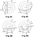
Figs. 6A to 6D are front views illustrating other waterproof connecting structures for a pipe; and -
Fig. 7 is a longitudinal sectional view illustrating another connecting space. - A waterproof connecting structure for a pipe according to a first embodiment of the invention is described.
-
Fig. 1 is a perspective, longitudinal sectional view of asurge tank 4 integrated with an intake manifold 2 used for an internal combustion engine for a vehicle. - The intake manifold 2 is integrally formed by joining a plurality of parts including a
surge tank 4 together by known technique such as vibration welding. The intake manifold 2 includes aguide portion 6 for guiding intake air in which intake air is supplied from a throttle valve connected with theguide portion 6. Intake air entering a space 4a in the surge tank 4 (indicated by a large arrow inFig.1 ) is sucked intosupply ports 8 of the respective cylinders (four cylinders here) and divided throughrespective passages 10 to the respective cylinders. - Within the space 4a in the
surge tank 4, apartition wall 12 is formed in an introduction passage for introducing intake air from theguide portion 6 to thesupply ports 8. Thepartition wall 12 faces downstream relative to the flow of intake air and includes an outer face parallel with the direction of gravitational force. As illustrated inFig, 2 , a connectingspace 14 is formed between thepartition wall 12 and an outerperipheral surface 4b of thesurge tank 4. -
Fig. 3 illustrates a longitudinal sectional view of the waterproof connecting structure and the related portions. The connectingspace 14 is a cylindrical space having an axis in a substantially horizontal direction or right-left direction inFig. 3 . The partition wall 12A closes one of the axial ends of the connectingspace 14 and includes ahole 14a. The connectingspace 14 communicates with the space 4a in thesurge tank 4 via thehole 14a. A wall of thesurge tank 4 on the side of the outerperipheral surface 4b, which corresponds to another one of axial ends of the connectingspace 14, includes afitting hole 14b at the center of the wall. Apressure conduit 16a of agas filter 16 is fitted into thefitting hole 14b in close contact with each other. A connectingconduit 16b is formed in the gas filter at the opposite side of thepressure conduit 16a. The connectingconduit 16b is connected with asuction pressure sensor 20 via arubber hose 18. Thus, intake pressure in the space 4a of thesurge tank 4 is conveyed through thehole 14a, the connectingspace 14, thegas filter 16, and therubber hose 18 to thesuction pressure sensor 20. - A
metal filter 16c and anon-woven filter 16d are disposed in thegas filter 16 in that order from thepressure conduit 16a and fixed withleaf springs - Referring now to
Fig. 4 . the positional relationship among the connectingspace 14, thehole 14a, and thedistal opening 16g of thepressure conduit 16a is illustrated. In particular, when viewed from the direction perpendicular to the outer face of thepartition wall 12, a lower side L1 in an arcuate line defining a part of thehole 14a is an extension of a part of the internal peripheral face of the connectingspace 14 in the axial direction of thereof and is the same with the line of the part of the internal peripheral face of the connectingspace 14. An upper side L2 in a straight line extending in a horizontal direction of thehole 14a is formed below a central axis C of the connectingspace 14. - The
pressure conduit 16a protrudes in the connectingspace 14 at the center of the connectingspace 14 so that the center of thedistal opening 16g of thepressure conduit 16a coincides with the central axis C of the connectingspace 14. Height H1 of a lower end of thedistal opening 16g of thepressure conduit 16a is lower than the height H2 of the upper side L2 of thehole 14a. Accordingly, when viewed from the direction perpendicular to thepartition wall 12, a part of a circular area defined by the contour line of thedistal opening 16g overlaps with a circular area of thehole 14a. - Now, a comparative study was conducted.
- As an Example 1, an intake manifold 2 as illustrated in
Fig. 4 was attached to a gasoline engine and a vehicle was traveled for 2 hours. After that, thegas filter 16 was removed to measure a weight of water that had entered therein. The diameter R1 of thedistal opening 16g of thepressure conduit 16a was 5 mm, the diameter R2 of the connectingspace 14 was 12 mm, and the height H2 from the lowermost end of the lower side L1 tao the upper side L2 was 5 mm. The axial length of the connectingspace 14 was about 20 mm and the distance between the outer face of thepartition wall 12 to thedistal opening 16g in the axial direction of thepressure conduit 16a was 25 mm. - As an Example 2, the same configuration as EXAMPLE 1 was used except that width S of a
hole 114a was made equal to the diameter R1 of thedistal opening 16g (5 mm), as illustrated inFig. 5 . As described above, after the vehicle to which the gasoline engine was attached was traveled for 3 hours, thegas filter 16 was removed to measure a weight of water that had entered therein. - As a Comparative Example, no connecting
space 14 was formed in thesurge tank 4 and thepressure conduit 16a was protruded directly into the space 4a of thesurge tank 4 and thegas filter 16 was attached thereto. After the vehicle was traveled for 2 hours, thegas filter 16 was removed to measure the weight of water that had entered therein. - The result was as follows:
- Example 1: 14 mg
- Example 2: 60 mg
- Comparative Example: 191 mg
- This result shows that the waterproof connecting structure for a pipe including the connecting
space 14, thepartition wall 12 and thehole Figs. 1 to 5 can prevent intrusion of water into thegas filter 16. - The area of the
hole 14a in Example 1 is made greater than that of thehole 114a in Example 2. Thus, it is expected that more droplets enter the connectingspace 14 from the space 4a of thesurge tank 4 in Example 1 than in Example 2. However; in fact, the amount of water that entered thegas filter 16 was less in Example 1 than in Example 2. The reason for this is presumed to be as follows. - That is, comparing the
hole 14a of Example 1 illustrated inFig. 4 with thehole 114a of Example 2 illustrated inFig. 5 , the amount of water droplets that enter the hole from the space 4a of thesurge tank 4 should be greater in Example 1 than in Example 2. However, since the shape of the open or transverse cross-sectional area of thehole 114a in Example 2 is generally square and not elongate, droplets attached around thehole 114a is likely to form a water membrane to block the entire hole 11 a rather than the case in Example 1. - Accordingly, water droplets are temporarily stored in the connecting
space 14, moved by pressure vibration in the space 4a, contacted with thedistal opening 16g of thepressure conduit 16a, and transferred into thegas filter 16. - On the other hand, the shape of the open or transverse cross-sectional area of the
hole 14a of Example 1 is elongate, i.e., thehole 14 has an arcuate lower side L1 and a straight upper side L2 as illustrated inFig. 4 . Therefore, the corners Y of thehole 14a are narrow so that attached water droplets are likely to stay in the corners Y. However, since thehole 14a is horizontally long, a water membrane is unlikely to generate over theentire hole 14a. Especially, thehole 14a is wide at the center and thus a water membrane is unlikely to occur at the center of thehole 14a. - Accordingly, drainage of water from the connecting
space 14 to the space 4a of the surge tank is not impaired as compared with the case in Example 2. Thus, less water accumulates in the connectingspace 14 and intrusion of the water into thegas filter 16 by pressure vibration is less likely to occur than in the case in Example 2. This is believed to be one reason why a difference in effect occurred between Example 1 and Example 2. - The first embodiment has the following advantages.
- (1)Water droplets drifting in intake air within the intake passage(or the surge tank 4) and water droplets conveyed along the wall surface of the
surge tank 4 sometimes reach thepartition wall 12. Even in that case, the possibility for these water droplets to reach thehole hole hole partition wall 12. - In addition, the shape of the open or transverse cross-sectional area of the
hole 14a as illustrated inFig. 4 is elongate (the ratio of the shorter length to the longer length is about 0.4, which is smaller than 1/2). In particular, thehole 14a is formed of two sides: one is a curved, or arcuate lower side L1 extending on an edge of thepartition wall 12 at a central angle less than 180° and the other is a straight upper side L2 extending horizontally. Thehole 14a gradually narrows from the center of thehole 14a toward the opposite ends, or the corners Y. - Since the
hole 14a ofFig. 4 has such a configuration, water tends to concentrate at the corners Y and a water membrane is unlikely to occur at the center due to surface tension properties. Thus, a water membrane over theentire hole 14a is unlikely to occur, allowing conveyance of gas to the gas detector (suction pressure sensor 20) via thehole 14a to be maintained in good condition. In addition, even if water droplets drifting in intake air enter into the connectingspace 14, they are readily drained to thesurge tank 4 via thehole 14a, the entire surface of which is not covered by a water membrane. Thus, both intrusion of the water droplets into the connectingspace 14 and duration of the water droplets in the connectingspace 14 are reduced. - Regarding the
hole 114a ofFig. 5 , water droplets are unlikely to enter the connectingspace 14 via thehole 114a as compared with thehole 14a ofFig. 4 . Even if thehole 114a is blocked by the water droplets, they are unlikely to intrude in thepressure conduit 16a. This is because thehole 114a is offset from the center of thedistal opening 16g of the pipe (thepressure conduit 16a) and thehole 114a is unlikely to contact with thedistal opening 16g even if a water membrane formed on the hole 11 a is vibrated by pressure vibration in thesurge tank 4. - The open areas of the
hole Figs. 4 and 5 are smaller than that of thepartition wall 12, and the transverse cross-sectional area of the connectingspace 14 is enlarged as compared with that of theholes space 14 will block theholes space 14 is also larger than that of thepressure conduit 16a. Accordingly, it is less likely that water having entered the connectingspace 14 will block thedistal opening 16g. - As such, the
holes Figs. 4 and 5 serve to reduce intrusion of water droplets drifting in through intake air as well as water droplets moving along the wall surface of thesurge tank 4. In addition, this water-proof connecting structure is achieved by providing thepressure conduit 16a with connectingspace 14, thepartition wall 12, and thehole surge tank 4 is extremely high. - (2) As illustrated in
Figs. 4 and 5 , the remaining part of thepartition wall 12 excluding thehole distal opening 16g ofpressure conduit 16a, when viewed from the direction perpendicular to thepartition wall 12. Thus, water droplets are less likely to enter thedistal opening 16g of thepressure conduit 16a, whereby water-proof properties are enhanced. - (3) The
hole 14a ofFig. 4 is offset to extend along the edge of thepartition wall 12, i.e., the lower side L1 corresponds to the edge of thepartition wall 12. The open or transverse cross-sectional area of thehole 14 is longer at the edge of thepartition wall 12 and shorter in the radial direction of thepartition wall 12. Thus, even if water enters and stays in the connectingspace 14, it will be easily discharged from inside the connectingspace 14 to thesurge tank 4. In addition, since thehole 14a extends along the edge of thepartition wall 12, thedistal opening 16g may be positioned to be offset from the center of thehole 14a when thepressure conduit 16a is disposed, whereby water-proof properties are enhanced. - The
hole 114a ofFig. 5 also extends along the edge of thepartition wall 12. Thus, similar to the case of thehole 14a, water within the connectingspace 14 can be easily discharged via thehole 114a to thesurge tank 4, whereby water-proof properties are enhanced. In addition, thedistal opening 16g may be positioned offset from the center of thehole 114a when thepressure conduit 16a is disposed, whereby water-proof properties are enhanced. - (4) When the amount of water intruded in the connecting
space 14 is Increased, water tends to move to a lowermost part of the connectingspace 14 in a gravitational direction. In this embodiment, the edge of thepartition wall 12 at which theholes partition wall 12. Thus, a large amount of water in the connectingspace 14 can be easily drained, whereby water-proof properties are enhanced. - (5) As illustrated in
Fig. 3 , the distal end of thepressure conduit 16a protrudes into the connectingspace 14 and thedistal opening 16g therein is spaced from the internal surface of the connectingspace 14. This configuration reduce or prevent water on the internal surface of the connectingspace 14 from entering thedistal opening 16g, whereby water-proof effect on thegas filter 16 or thesuction pressure sensor 20 is enhanced. - The waterproof connecting structure for a pipe of the first embodiment is applied to the pipe connection of
suction pressure sensor 20 for measuring air pressure in an intake passage of an internal combustion engine, which enables sufficient waterproofing against water droplets drifting in through intake air. In addition, the waterproof connecting structure may be formed by providing the connectingspace 14, thepartition wall 12, and thehole pressure conduit 16a. Thus, the degree of freedom of location to attach the structure to thesurge tank 4 is extremely high. Thesuction pressure sensor 20 is thus readily applicable to various kinds of internal combustion engines to detect suction pressure with high accuracy. - (6) Water is also unlikely to enter the
gas filter 16, which is closer to thesurge tank 4 than thesuction pressure sensor 20. That is, breakage of thegas filter 16 due to the water residing therein or freeze of such water is prevented. - The above embodiment may be modified as follows.
- In the first embodiment, the
hole 14a is located on the side of the edge of thepartition wall 12, wherein the edge is the lowermost part of thepartition wall 12 in a gravitational direction. Alternatively, as illustrated inFig. 6A , the hole may be located on the side of the edge which is a middle part of thepartition wall 12 in a gravitational direction, as illustrated as ahole 214a. In such a case, water in the connectingspace 14 drains from a lower end of thehole 214a to the surge tank. Thus, a similar effect as in thehole 14a ofFig. 4 can be obtained. - As illustrated in
Fig. 6B , the upper side may be upwardly convex as a hole 314a having a convex upper side L3, instead of the straight upper side L2 inFig. 4 . In this configuration, the hole 314a is wide at the center, which is effective in improving drainage of water. - As illustrated in
Fig. 6C , the upper side may also be downwardly convex as ahole 414a having a concave upper side L4. In this configuration, the hole 314a is narrow at the center, which is effective in reducing or preventing intrusion of water droplets. Further, thepartition wall 12 coincides with the entiredistal opening 16g, which is effective in reducing or preventing intrusion of water droplets into thedistal opening 16g. - As illustrated in
Fig. 6D , the opposite ends of the upper side L5 may be located on the horizontal phantom line passing the central axis C and only a center portion of the upper side L5 may be protruded toward the lower side L6. Then, the protruded line M may coincide with the entiredistal opening 16g of the pressure conduit when viewed from a direction perpendicular to thepartition wall 12. This configuration is effective to reduce or prevent direct intrusion of water droplets into thedistal opening 16g. - As illustrated in
Fig. 7 , when viewed from the direction perpendicular to thepartition wall 12, the position of thehole 614a and that of the distal opening 616g of thepressure conduit 616a may be offset greatly by making the connectingspace 614 in the form of cylinder have a large diameter. In such a case, thehole 614a is positioned at the lowermost part of thepartition wall 612 in a gravitational direction and thepressure conduit 616a is positioned as uppermost in a gravitational direction as possible. This configuration prevents water droplets from reaching the distal opening 616g even when a large amount of the water droplets enters the connectingspace 614 from inside thesurge tank 604 temporarily and accumulates in the connectingspace 614. - In the above embodiments, the partition wall, in which the hole is formed, is an outer face parallel with the direction of gravitational force that faces in a downstream of the flow of intake air in the surge tank. However, the partition wall may be positioned in another part in the surge tank. For example, the partition may face downward and extends in a horizontal direction or may extend obliquely downwardly.
Claims (10)
- A waterproof connecting structure for a pipe for connecting an intake passage of an internal combustion engine and an external gas detector to convey gas from the intake passage, wherein the pipe includes a distal opening (16g) having a center (C), the structure comprising:a connecting space (14) to which the pipe is connected, wherein the connecting space (l4) has a larger diameter than the pipe;a partition wall (12) formed between the intake passage and the connecting space (14), characterized in thatthe partition wall (12) includes an hole (14a) on the side wall of the intake passage for placing the intake passage and the connecting space (14) in fluid communication, wherein the hole (14a, 314a, 414a, 514a, 614a) is offset, from the centre (C) of the distal opening (16g) of the pipe, to extend along an edge of the partition wall (12).
- The waterproof connecting structure for a pipe of claim 1, wherein the hole (14a, 314a, 414a, 514a, 6.14a) has a traverse cross-sectional area having a shorter length and a longer length and wherein the hole (14a, 314a, 414a, 514a, 614a) extends longer along the edge and extends shorter in a radial direction of the partition wall (12).
- The waterproof connecting structure for a pipe of Claim 2, characterized in that a part of the partition wall (12) other than the hole (14a, 314a, 414a, 514a, 614a) overlaps with a part or all of a distal opening (16g) of the pipe, when viewed from a direction perpendicular to the partition wall (12).
- The waterproof connecting structure for a pipe of Claim 2 or 3, characterized in that a ratio of the shorter length to the longer length in the transverse cross-sectional area of the hole (1-4a) is ½ or less.
- The waterproof connecting structure for a pipe of any one of Claims 1 to 4, characterized in that a distal end of the pipe protrudes into the connecting space (14) and the distal opening (16g) of the pipe is spaced from an internal surface of the connecting space (14).
- The waterproof connecting structure for a pipe of any one of Claims 1 to 5, characterized in that the connecting space (14) is a cylindrical space, wherein the hole (14a, 114a, 314a, 414a, 614a) is formed of two sides, with one side defining the hole (14a, 114a, 314a, 414a, 614a) by a curvature extending along the edge of the partition wall (12) at a central angle less than 180° and the other being a straight or curved side.
- The waterproof connecting structure for a pipe of any one of Claims 1 to 5, characterized in that the connecting space (14) is a cylindrical space, wherein the hole (514a) is formed of two sides, with one side (L6) defining the hole (514a) by a curvature extending along the edge of the partition wall (12) and
wherein opposite ends (15) of the second side are located on a straight line, and a center portion (M) of the second side protrudes towards the first side. - The waterproof connecting structure for a pipe of any one of Claims 1 to 7, characterized in that the gas detector is a suction pressure sensor (20) for measuring air pressure in the intake passage .
- The waterproof connecting structure for a pipe of any one of Claims 1 to 8, characterized in that a gas filter (16) is provided in the pipe.
- The waterproof connecting structure for a pipe of any one of claims 1 to 9, wherein the edge on which the hole (14a, 314a, 414a, 514a, 614a) extends is an edge including a lowermost part of the partition wall (12) relative to gravitational direction.
Applications Claiming Priority (2)
| Application Number | Priority Date | Filing Date | Title |
|---|---|---|---|
| JP2007159441A JP4792427B2 (en) | 2007-06-15 | 2007-06-15 | Piping waterproof connection structure |
| PCT/JP2008/061274 WO2008153213A1 (en) | 2007-06-15 | 2008-06-13 | Waterproof connecting structure for pipe |
Publications (2)
| Publication Number | Publication Date |
|---|---|
| EP2145097A1 EP2145097A1 (en) | 2010-01-20 |
| EP2145097B1 true EP2145097B1 (en) | 2012-05-02 |
Family
ID=39745568
Family Applications (1)
| Application Number | Title | Priority Date | Filing Date |
|---|---|---|---|
| EP08777424A Not-in-force EP2145097B1 (en) | 2007-06-15 | 2008-06-13 | Waterproof connecting structure for pipe |
Country Status (6)
| Country | Link |
|---|---|
| US (1) | US8359910B2 (en) |
| EP (1) | EP2145097B1 (en) |
| JP (1) | JP4792427B2 (en) |
| CN (1) | CN101680399B (en) |
| AT (1) | ATE556214T1 (en) |
| WO (1) | WO2008153213A1 (en) |
Families Citing this family (5)
| Publication number | Priority date | Publication date | Assignee | Title |
|---|---|---|---|---|
| JP5534855B2 (en) * | 2010-02-22 | 2014-07-02 | ヤンマー株式会社 | engine |
| CN102305159A (en) * | 2011-08-26 | 2012-01-04 | 上汽通用五菱汽车股份有限公司 | Engine dual-fuel plastic air inlet manifold |
| JP5814106B2 (en) * | 2011-12-26 | 2015-11-17 | トヨタ自動車株式会社 | Intake manifold |
| JP6915409B2 (en) * | 2017-06-30 | 2021-08-04 | トヨタ紡織株式会社 | Intake manifold |
| KR102586328B1 (en) * | 2018-08-27 | 2023-10-06 | 현대자동차 주식회사 | Intake manifold and engine having the same |
Family Cites Families (22)
| Publication number | Priority date | Publication date | Assignee | Title |
|---|---|---|---|---|
| JPS5866034A (en) * | 1981-10-14 | 1983-04-20 | Nippon Denso Co Ltd | Pressure detecting apparatus |
| US4489595A (en) * | 1983-03-28 | 1984-12-25 | General Motors Corporation | Engine air inlet pressure measurement |
| JPS6093328A (en) * | 1983-10-26 | 1985-05-25 | Fujitsu Ten Ltd | Detection for pressure of intake air in internal combustion engine |
| JPS63233294A (en) | 1987-03-20 | 1988-09-28 | Agency Of Ind Science & Technol | Gas liquid separation type vertical thermo siphon |
| JP2732665B2 (en) * | 1988-07-08 | 1998-03-30 | 株式会社日本自動車部品総合研究所 | Intake pipe pressure detector |
| US5939628A (en) * | 1995-05-30 | 1999-08-17 | Hitachi, Ltd. | Thermal type air flow measuring instrument for internal combustion engine |
| DE19517676B4 (en) * | 1995-05-13 | 2008-01-31 | Robert Bosch Gmbh | Pressure sensor for an internal combustion engine with an intake pipe |
| JPH0968066A (en) | 1995-08-29 | 1997-03-11 | Daihatsu Motor Co Ltd | Intake air pressure detecting device of internal combustion engine |
| US5804718A (en) * | 1996-04-24 | 1998-09-08 | Denso Corporation | Airflow meter having an inverted u-shape bypass passage |
| JPH11141417A (en) * | 1997-11-06 | 1999-05-25 | Toyota Motor Corp | Surge tank |
| JPH11159367A (en) * | 1997-11-28 | 1999-06-15 | Nippon Soken Inc | Passage for pressure transmission in the intake pipe |
| JP2000088688A (en) * | 1998-09-11 | 2000-03-31 | Nippon Soken Inc | Pressure detector for internal combustion engine |
| US6604424B1 (en) | 1999-06-16 | 2003-08-12 | Denso Corporation | Pressure detecting apparatus and installation structure of same |
| DE19934832A1 (en) * | 1999-07-24 | 2001-01-25 | Bosch Gmbh Robert | Pressure sensor for IC engine air intake pipe has anti-freeze fluid in section of sensor channel coupling pressure sensor to air intake pipe closest to sensor surface |
| JP2004285899A (en) * | 2003-03-20 | 2004-10-14 | Keihin Corp | Throttle body |
| JP3848934B2 (en) * | 2003-05-16 | 2006-11-22 | 三菱電機株式会社 | Air flow measurement device |
| JP2005048597A (en) * | 2003-07-29 | 2005-02-24 | Kojima Press Co Ltd | Pressure lead-out port structure for air connector |
| JP4357233B2 (en) * | 2003-07-31 | 2009-11-04 | トヨタ自動車株式会社 | Internal combustion engine surge tank |
| JP4422654B2 (en) * | 2005-08-02 | 2010-02-24 | トヨタ自動車株式会社 | Intake manifold |
| JP4814164B2 (en) * | 2007-07-17 | 2011-11-16 | 本田技研工業株式会社 | Intake device for internal combustion engine |
| US7938105B2 (en) * | 2007-09-25 | 2011-05-10 | Ford Global Technologies, Llc | High flow (delta P) differential pressure EGR system with provision for both flow control and OBD monitor |
| JP5015827B2 (en) * | 2008-03-05 | 2012-08-29 | トヨタ自動車株式会社 | Intake path gas introduction structure and intake manifold |
-
2007
- 2007-06-15 JP JP2007159441A patent/JP4792427B2/en not_active Expired - Fee Related
-
2008
- 2008-06-13 AT AT08777424T patent/ATE556214T1/en active
- 2008-06-13 WO PCT/JP2008/061274 patent/WO2008153213A1/en not_active Ceased
- 2008-06-13 CN CN2008800177428A patent/CN101680399B/en not_active Expired - Fee Related
- 2008-06-13 US US12/602,971 patent/US8359910B2/en not_active Expired - Fee Related
- 2008-06-13 EP EP08777424A patent/EP2145097B1/en not_active Not-in-force
Also Published As
| Publication number | Publication date |
|---|---|
| JP2008309112A (en) | 2008-12-25 |
| EP2145097A1 (en) | 2010-01-20 |
| JP4792427B2 (en) | 2011-10-12 |
| ATE556214T1 (en) | 2012-05-15 |
| US8359910B2 (en) | 2013-01-29 |
| US20100164225A1 (en) | 2010-07-01 |
| CN101680399A (en) | 2010-03-24 |
| CN101680399B (en) | 2012-06-13 |
| WO2008153213A1 (en) | 2008-12-18 |
Similar Documents
| Publication | Publication Date | Title |
|---|---|---|
| KR101291458B1 (en) | Filter device | |
| US8359910B2 (en) | Waterproof connecting structure for pipe | |
| US8991352B2 (en) | Intake manifold section and intake system | |
| CA2674911A1 (en) | Exhaust device of internal combustion engine | |
| US8210061B2 (en) | Gas sensor fitting structure | |
| JP7188272B2 (en) | blow-by gas treatment equipment | |
| CN101495858A (en) | Gas sensor mounting structure | |
| JP2010014008A (en) | Off-road vehicle | |
| ES2356902T3 (en) | INTAKE AIR NEGATIVE PRESSURE DETECTOR FOR INTERNAL COMBUSTION ENGINE. | |
| US7131433B1 (en) | Positive crankcase ventilation valve assembly | |
| JP2010084641A (en) | Surge tank of internal combustion engine and intake manifold | |
| JPH06229221A (en) | Blow-by gas recirculation device | |
| JP3791737B2 (en) | Engine cylinder head cover | |
| US20230149845A1 (en) | Air cleaner | |
| US7249582B2 (en) | Intake apparatus | |
| JPH08261080A (en) | Throttle body pressure introduction passage structure | |
| US6016781A (en) | Pressure-detecting device for internal combustion engine | |
| US8986059B1 (en) | Marine propulsion device | |
| US20210172354A1 (en) | Head cover structure | |
| CN112815127B (en) | Pressure regulating valve and control system thereof, and smoke concentration measuring device having the same | |
| JP2013124591A (en) | Outboard motor, and watercraft having the same | |
| EP1701012B1 (en) | Exhaust gas purifying device | |
| US8240128B2 (en) | Exhaust system with O2 sensor | |
| EP3128167B1 (en) | Leakage detection device for a double walled fluid pipe | |
| JP2008038858A (en) | Intake device for vehicle engine |
Legal Events
| Date | Code | Title | Description |
|---|---|---|---|
| PUAI | Public reference made under article 153(3) epc to a published international application that has entered the european phase |
Free format text: ORIGINAL CODE: 0009012 |
|
| 17P | Request for examination filed |
Effective date: 20091103 |
|
| AK | Designated contracting states |
Kind code of ref document: A1 Designated state(s): AT BE BG CH CY CZ DE DK EE ES FI FR GB GR HR HU IE IS IT LI LT LU LV MC MT NL NO PL PT RO SE SI SK TR |
|
| AX | Request for extension of the european patent |
Extension state: AL BA MK RS |
|
| 17Q | First examination report despatched |
Effective date: 20100208 |
|
| DAX | Request for extension of the european patent (deleted) | ||
| GRAP | Despatch of communication of intention to grant a patent |
Free format text: ORIGINAL CODE: EPIDOSNIGR1 |
|
| GRAS | Grant fee paid |
Free format text: ORIGINAL CODE: EPIDOSNIGR3 |
|
| RIN1 | Information on inventor provided before grant (corrected) |
Inventor name: ISHIKAWA, HIROAKI Inventor name: INOUE, CHIKARA Inventor name: NAKAMORI, IKUMASA Inventor name: ITO, ATSUSHI Inventor name: SHINKAI, FUMIHIRO Inventor name: YAMADA, TETSU |
|
| RAP1 | Party data changed (applicant data changed or rights of an application transferred) |
Owner name: TOYOTA JIDOSHA KABUSHIKI KAISHA Owner name: AISIN SEIKI KABUSHIKI KAISHA |
|
| GRAA | (expected) grant |
Free format text: ORIGINAL CODE: 0009210 |
|
| AK | Designated contracting states |
Kind code of ref document: B1 Designated state(s): AT BE BG CH CY CZ DE DK EE ES FI FR GB GR HR HU IE IS IT LI LT LU LV MC MT NL NO PL PT RO SE SI SK TR |
|
| REG | Reference to a national code |
Ref country code: GB Ref legal event code: FG4D |
|
| REG | Reference to a national code |
Ref country code: CH Ref legal event code: EP Ref country code: AT Ref legal event code: REF Ref document number: 556214 Country of ref document: AT Kind code of ref document: T Effective date: 20120515 |
|
| REG | Reference to a national code |
Ref country code: IE Ref legal event code: FG4D |
|
| REG | Reference to a national code |
Ref country code: DE Ref legal event code: R096 Ref document number: 602008015400 Country of ref document: DE Effective date: 20120705 |
|
| REG | Reference to a national code |
Ref country code: NL Ref legal event code: VDEP Effective date: 20120502 |
|
| REG | Reference to a national code |
Ref country code: LT Ref legal event code: MG4D Effective date: 20120502 |
|
| PG25 | Lapsed in a contracting state [announced via postgrant information from national office to epo] |
Ref country code: SE Free format text: LAPSE BECAUSE OF FAILURE TO SUBMIT A TRANSLATION OF THE DESCRIPTION OR TO PAY THE FEE WITHIN THE PRESCRIBED TIME-LIMIT Effective date: 20120502 Ref country code: CY Free format text: LAPSE BECAUSE OF FAILURE TO SUBMIT A TRANSLATION OF THE DESCRIPTION OR TO PAY THE FEE WITHIN THE PRESCRIBED TIME-LIMIT Effective date: 20120502 Ref country code: FI Free format text: LAPSE BECAUSE OF FAILURE TO SUBMIT A TRANSLATION OF THE DESCRIPTION OR TO PAY THE FEE WITHIN THE PRESCRIBED TIME-LIMIT Effective date: 20120502 Ref country code: NO Free format text: LAPSE BECAUSE OF FAILURE TO SUBMIT A TRANSLATION OF THE DESCRIPTION OR TO PAY THE FEE WITHIN THE PRESCRIBED TIME-LIMIT Effective date: 20120802 Ref country code: IS Free format text: LAPSE BECAUSE OF FAILURE TO SUBMIT A TRANSLATION OF THE DESCRIPTION OR TO PAY THE FEE WITHIN THE PRESCRIBED TIME-LIMIT Effective date: 20120902 Ref country code: PL Free format text: LAPSE BECAUSE OF FAILURE TO SUBMIT A TRANSLATION OF THE DESCRIPTION OR TO PAY THE FEE WITHIN THE PRESCRIBED TIME-LIMIT Effective date: 20120502 Ref country code: LT Free format text: LAPSE BECAUSE OF FAILURE TO SUBMIT A TRANSLATION OF THE DESCRIPTION OR TO PAY THE FEE WITHIN THE PRESCRIBED TIME-LIMIT Effective date: 20120502 |
|
| REG | Reference to a national code |
Ref country code: AT Ref legal event code: MK05 Ref document number: 556214 Country of ref document: AT Kind code of ref document: T Effective date: 20120502 |
|
| PG25 | Lapsed in a contracting state [announced via postgrant information from national office to epo] |
Ref country code: LV Free format text: LAPSE BECAUSE OF FAILURE TO SUBMIT A TRANSLATION OF THE DESCRIPTION OR TO PAY THE FEE WITHIN THE PRESCRIBED TIME-LIMIT Effective date: 20120502 Ref country code: PT Free format text: LAPSE BECAUSE OF FAILURE TO SUBMIT A TRANSLATION OF THE DESCRIPTION OR TO PAY THE FEE WITHIN THE PRESCRIBED TIME-LIMIT Effective date: 20120903 Ref country code: HR Free format text: LAPSE BECAUSE OF FAILURE TO SUBMIT A TRANSLATION OF THE DESCRIPTION OR TO PAY THE FEE WITHIN THE PRESCRIBED TIME-LIMIT Effective date: 20120502 Ref country code: SI Free format text: LAPSE BECAUSE OF FAILURE TO SUBMIT A TRANSLATION OF THE DESCRIPTION OR TO PAY THE FEE WITHIN THE PRESCRIBED TIME-LIMIT Effective date: 20120502 Ref country code: GR Free format text: LAPSE BECAUSE OF FAILURE TO SUBMIT A TRANSLATION OF THE DESCRIPTION OR TO PAY THE FEE WITHIN THE PRESCRIBED TIME-LIMIT Effective date: 20120803 |
|
| PG25 | Lapsed in a contracting state [announced via postgrant information from national office to epo] |
Ref country code: BE Free format text: LAPSE BECAUSE OF FAILURE TO SUBMIT A TRANSLATION OF THE DESCRIPTION OR TO PAY THE FEE WITHIN THE PRESCRIBED TIME-LIMIT Effective date: 20120502 |
|
| PG25 | Lapsed in a contracting state [announced via postgrant information from national office to epo] |
Ref country code: MC Free format text: LAPSE BECAUSE OF NON-PAYMENT OF DUE FEES Effective date: 20120630 Ref country code: CZ Free format text: LAPSE BECAUSE OF FAILURE TO SUBMIT A TRANSLATION OF THE DESCRIPTION OR TO PAY THE FEE WITHIN THE PRESCRIBED TIME-LIMIT Effective date: 20120502 Ref country code: DK Free format text: LAPSE BECAUSE OF FAILURE TO SUBMIT A TRANSLATION OF THE DESCRIPTION OR TO PAY THE FEE WITHIN THE PRESCRIBED TIME-LIMIT Effective date: 20120502 Ref country code: SK Free format text: LAPSE BECAUSE OF FAILURE TO SUBMIT A TRANSLATION OF THE DESCRIPTION OR TO PAY THE FEE WITHIN THE PRESCRIBED TIME-LIMIT Effective date: 20120502 Ref country code: EE Free format text: LAPSE BECAUSE OF FAILURE TO SUBMIT A TRANSLATION OF THE DESCRIPTION OR TO PAY THE FEE WITHIN THE PRESCRIBED TIME-LIMIT Effective date: 20120502 Ref country code: AT Free format text: LAPSE BECAUSE OF FAILURE TO SUBMIT A TRANSLATION OF THE DESCRIPTION OR TO PAY THE FEE WITHIN THE PRESCRIBED TIME-LIMIT Effective date: 20120502 Ref country code: NL Free format text: LAPSE BECAUSE OF FAILURE TO SUBMIT A TRANSLATION OF THE DESCRIPTION OR TO PAY THE FEE WITHIN THE PRESCRIBED TIME-LIMIT Effective date: 20120502 Ref country code: RO Free format text: LAPSE BECAUSE OF FAILURE TO SUBMIT A TRANSLATION OF THE DESCRIPTION OR TO PAY THE FEE WITHIN THE PRESCRIBED TIME-LIMIT Effective date: 20120502 |
|
| REG | Reference to a national code |
Ref country code: CH Ref legal event code: PL |
|
| REG | Reference to a national code |
Ref country code: CH Ref legal event code: PL |
|
| RAP2 | Party data changed (patent owner data changed or rights of a patent transferred) |
Owner name: TOYOTA JIDOSHA KABUSHIKI KAISHA Owner name: AISIN SEIKI KABUSHIKI KAISHA |
|
| PG25 | Lapsed in a contracting state [announced via postgrant information from national office to epo] |
Ref country code: IT Free format text: LAPSE BECAUSE OF FAILURE TO SUBMIT A TRANSLATION OF THE DESCRIPTION OR TO PAY THE FEE WITHIN THE PRESCRIBED TIME-LIMIT Effective date: 20120502 |
|
| PLBE | No opposition filed within time limit |
Free format text: ORIGINAL CODE: 0009261 |
|
| STAA | Information on the status of an ep patent application or granted ep patent |
Free format text: STATUS: NO OPPOSITION FILED WITHIN TIME LIMIT |
|
| REG | Reference to a national code |
Ref country code: IE Ref legal event code: MM4A |
|
| 26N | No opposition filed |
Effective date: 20130205 |
|
| PG25 | Lapsed in a contracting state [announced via postgrant information from national office to epo] |
Ref country code: CH Free format text: LAPSE BECAUSE OF NON-PAYMENT OF DUE FEES Effective date: 20120630 Ref country code: ES Free format text: LAPSE BECAUSE OF FAILURE TO SUBMIT A TRANSLATION OF THE DESCRIPTION OR TO PAY THE FEE WITHIN THE PRESCRIBED TIME-LIMIT Effective date: 20120813 Ref country code: LI Free format text: LAPSE BECAUSE OF NON-PAYMENT OF DUE FEES Effective date: 20120630 Ref country code: IE Free format text: LAPSE BECAUSE OF NON-PAYMENT OF DUE FEES Effective date: 20120613 |
|
| REG | Reference to a national code |
Ref country code: DE Ref legal event code: R097 Ref document number: 602008015400 Country of ref document: DE Effective date: 20130205 |
|
| PG25 | Lapsed in a contracting state [announced via postgrant information from national office to epo] |
Ref country code: BG Free format text: LAPSE BECAUSE OF FAILURE TO SUBMIT A TRANSLATION OF THE DESCRIPTION OR TO PAY THE FEE WITHIN THE PRESCRIBED TIME-LIMIT Effective date: 20120802 Ref country code: MT Free format text: LAPSE BECAUSE OF FAILURE TO SUBMIT A TRANSLATION OF THE DESCRIPTION OR TO PAY THE FEE WITHIN THE PRESCRIBED TIME-LIMIT Effective date: 20120502 |
|
| PG25 | Lapsed in a contracting state [announced via postgrant information from national office to epo] |
Ref country code: TR Free format text: LAPSE BECAUSE OF FAILURE TO SUBMIT A TRANSLATION OF THE DESCRIPTION OR TO PAY THE FEE WITHIN THE PRESCRIBED TIME-LIMIT Effective date: 20120502 |
|
| PG25 | Lapsed in a contracting state [announced via postgrant information from national office to epo] |
Ref country code: LU Free format text: LAPSE BECAUSE OF NON-PAYMENT OF DUE FEES Effective date: 20120613 |
|
| PG25 | Lapsed in a contracting state [announced via postgrant information from national office to epo] |
Ref country code: HU Free format text: LAPSE BECAUSE OF FAILURE TO SUBMIT A TRANSLATION OF THE DESCRIPTION OR TO PAY THE FEE WITHIN THE PRESCRIBED TIME-LIMIT Effective date: 20080613 |
|
| REG | Reference to a national code |
Ref country code: DE Ref legal event code: R084 Ref document number: 602008015400 Country of ref document: DE |
|
| REG | Reference to a national code |
Ref country code: GB Ref legal event code: 746 Effective date: 20160411 |
|
| REG | Reference to a national code |
Ref country code: FR Ref legal event code: PLFP Year of fee payment: 9 |
|
| REG | Reference to a national code |
Ref country code: FR Ref legal event code: PLFP Year of fee payment: 10 |
|
| REG | Reference to a national code |
Ref country code: FR Ref legal event code: PLFP Year of fee payment: 11 |
|
| PGFP | Annual fee paid to national office [announced via postgrant information from national office to epo] |
Ref country code: FR Payment date: 20200512 Year of fee payment: 13 Ref country code: DE Payment date: 20200602 Year of fee payment: 13 |
|
| PGFP | Annual fee paid to national office [announced via postgrant information from national office to epo] |
Ref country code: GB Payment date: 20200603 Year of fee payment: 13 |
|
| REG | Reference to a national code |
Ref country code: DE Ref legal event code: R119 Ref document number: 602008015400 Country of ref document: DE |
|
| GBPC | Gb: european patent ceased through non-payment of renewal fee |
Effective date: 20210613 |
|
| PG25 | Lapsed in a contracting state [announced via postgrant information from national office to epo] |
Ref country code: GB Free format text: LAPSE BECAUSE OF NON-PAYMENT OF DUE FEES Effective date: 20210613 Ref country code: DE Free format text: LAPSE BECAUSE OF NON-PAYMENT OF DUE FEES Effective date: 20220101 |
|
| PG25 | Lapsed in a contracting state [announced via postgrant information from national office to epo] |
Ref country code: FR Free format text: LAPSE BECAUSE OF NON-PAYMENT OF DUE FEES Effective date: 20210630 |