EP2144537B1 - Seat for chairs or armchairs particularly an adjustable office type - Google Patents
Seat for chairs or armchairs particularly an adjustable office type Download PDFInfo
- Publication number
- EP2144537B1 EP2144537B1 EP08754285A EP08754285A EP2144537B1 EP 2144537 B1 EP2144537 B1 EP 2144537B1 EP 08754285 A EP08754285 A EP 08754285A EP 08754285 A EP08754285 A EP 08754285A EP 2144537 B1 EP2144537 B1 EP 2144537B1
- Authority
- EP
- European Patent Office
- Prior art keywords
- load
- seat
- support body
- bearing base
- bearing structure
- Prior art date
- Legal status (The legal status is an assumption and is not a legal conclusion. Google has not performed a legal analysis and makes no representation as to the accuracy of the status listed.)
- Not-in-force
Links
Images





Classifications
-
- A—HUMAN NECESSITIES
- A47—FURNITURE; DOMESTIC ARTICLES OR APPLIANCES; COFFEE MILLS; SPICE MILLS; SUCTION CLEANERS IN GENERAL
- A47C—CHAIRS; SOFAS; BEDS
- A47C7/00—Parts, details, or accessories of chairs or stools
- A47C7/02—Seat parts
-
- A—HUMAN NECESSITIES
- A47—FURNITURE; DOMESTIC ARTICLES OR APPLIANCES; COFFEE MILLS; SPICE MILLS; SUCTION CLEANERS IN GENERAL
- A47C—CHAIRS; SOFAS; BEDS
- A47C4/00—Foldable, collapsible or dismountable chairs
- A47C4/02—Dismountable chairs
-
- A—HUMAN NECESSITIES
- A47—FURNITURE; DOMESTIC ARTICLES OR APPLIANCES; COFFEE MILLS; SPICE MILLS; SUCTION CLEANERS IN GENERAL
- A47C—CHAIRS; SOFAS; BEDS
- A47C4/00—Foldable, collapsible or dismountable chairs
- A47C4/02—Dismountable chairs
- A47C4/028—Upholstered chairs, e.g. metal, plastic or wooden chairs
Definitions
- the present invention relates to a seat for chairs or armchairs, particularly the adjustable office type.
- Chairs or armchairs particularly for office use, are known that comprise a seat possibly paired to a backrest and a pair of arm rests and which are of the adjustable type in particular as relates to the tilt of the seat and backrest.
- adjustable armchairs are generally complex and comprises a plurality of components connected and articulated to each other, which make their production especially costly.
- a theatre chair with removable seat member and backrest member is describes in AU 2007 200 895 A1 .
- Another purpose of the present invention is to provide a seat for chairs or armchairs that makes it possible to satisfy the changing market demands by reducing the number of components to modify, thus reducing waste of materials.
- Another purpose of the present invention is to provide a seat for chairs or armchairs which is versatile and flexible to use, and which can be applied easily and without requiring special modifications to known tilt adjustment devices.
- Another purpose of the present invention is to fulfill the previous tasks with a simple structure, relatively easy to operate, safe to use and effective to operate, as well as relatively inexpensive to produce.
- Embodiments of the present invention provide a seat for chairs or armchairs, which is characterized by load-bearing structure compatible with the frame of a chair or armchair, a removable type seat surface overlapping the load-bearing structure and connection means for coupling seat surface to the load-bearing structure, said load - bearing structure comprising at least one support arm.
- the removable type connection means is a quick release type.
- reference numeral 1 is used to broadly indicate a seat for chairs or armchairs in particular, reclining office type.
- the term "seat” is used to indicate all elements which define the support plane of a chair or armchair and which, in general, is paired to a backrest and, optionally, armrests.
- the seat 1 comprises a load-bearing structure 2, a removable type seat surface 3 which overlaps the load-bearing structure 2 and a connection means 4 to couple the seat surface 3 to the load-bearing structure 2.
- the load-bearing structure 2 is compatible with the frame of a chair or armchair, in particular to the pedestal of an office chair (not shown in the detail).
- the load-bearing structure 2 includes a support body 5 which is compatible with the frame of the chair or armchair and a load-bearing base 6 to which the seat surface 3 is connected.
- the load-bearing base 6 is slidingly paired to the support body 5 along its longitudinal axis 6A, and is provided with a stop means 7 for supporting sliding of the load-bearing base 6 relative to the support body 5.
- the seat surface 3 is formed with a padding support panel 8 and at least one padding layer 9 firmly connected to the support panel 8.
- the padding layer 9 is affixed to the support panel 8 by bonding or comolding so as to form a single body, though other connecting schemes can be envisioned.
- connection means 4 which removably join the seat surface 3 to the load-bearing structure 2, are of a quick release type.
- the connecting means is formed by pairs of tabs 10 which overhanging the side of the load-bearing base 6 turned toward the support panel 8, and each of which is provided with a retaining tooth 11.
- the pairs of tabs 10 are quick release insertible within the corresponding seats 12 defined in the support plane 8, or vice-versa.
- the radial dimensions of the load-bearing structure 2 in a plan view is smaller and is contained within the radial dimension of the seat surface ( see Figure 3 ).
- the radial dimension of the load-bearing base 6, which substantially has the form of a plate is less and is contained within the radial dimension of the padding layer 9 which wraps around the perimeter edge of the support panel 8.
- the radial dimension of the support body 5, which also substantially has the form of a plate is less and is contained within the radial dimension of the load-bearing base 6.
- the profile of the seat surface 3 is linked to the profile of the load-bearing structure 2, as shown in Figure 2 .
- the profile of the portion of padding layer 9 what wraps around the perimeter edge of the support panel 8 connects and continues the course of the profile of the load-bearing base 6.
- Figures 2 and 3 show, in a continuous line one embodiment of the seat surface 3 and in particular of the padding layer 9 and, in a dotted line, another embodiment thereof, wider and of a different configuration respectively.
- the different seat surfaces 3 differ by the different design of the padding layer 9, and the possibly (though riot necessarily) by the shape of the support panel 8. Replacement of the seat surface 3 is simple and easy due to the removable type connection means 4 and in particular of quick release type that affixes the seat surface 3 to the load-bearing structure 2.
- the load-bearing base 6, to which the seat surface 3 is firmly connected and removable, is slidingly paired to the support body 5 along longitudinal axis 6A.
- the load-bearing base 6 has a pair of machined rectilinear guides parallel to longitudinal axis 6A each of which is formed as a groove 13 along which are longitudinally machined buttonholes 14. Inside each rectilinear track there is slidingly housed in both directions at least one runner 15 fastened to the support body 5.
- each runner 15 and the respective rectilinear track is defined a form connection that prevents reciprocal detachment along the transversal directions to axis 6A, the skids 15 thus acting as transfer elements for the load-bearing base 6 on the support body 5.
- each runner 15 comprises a nut 16 which has one end affixed to the side of the support body 5 facing the load-bearing base 6 and which extends through the respective buttonhole 14. At the opposite end of the nut 16 there is formed a head 17, which widens to the sides of the buttonhole 14 so as to define said form connection.
- the runner 15 is fastened to the support body 5 with a screw 18 or other fastener that passes through the thickness of the support body 5 to engage a nut 19 housed in a cavity machined in the head 17.
- Each runner 15 is formed by one or more flexible tabs 20 machined from one or both of its opposite ends, along the slide path. Flexible tabs 20 extend from the opposite ends of head 17 of each runner 15.
- Stop means 7 of the sliding of the load-bearing base 6 relative to the support body 5 includes at least one rack 21, which is machined in the support body 5 and extends in a parallel direction to the longitudinal axis 6A, and an engagement element 22 formed by one or more stop teeth cooperating with the rack 21 and which is paired to the load-bearing base 6.
- Engagement element 22 is movably paired to the load-bearing base 6 between an engaged configuration and a release or disengagement configuration with the rack 21, elastic thrust means being provided, comprising a spring 23, capable of maintaining the engagement element 22 in the engaged configuration.
- the stop teeth are engaged with the rack 21 to block the sliding of the load-bearing base 6 relative to the support body 5.
- the stop teeth are disengaged from the rack 21 to release the sliding of the load-bearing base 6 relative to the support body 5.
- the stop means 7 also includes a push-button device for controlling movement of the engagement element 22 between the two configurations.
- a push-button device is formed by a pin 24 that is provided parallel to the rack 21 and which is rotatively supported around its own axis by a pair of first supports 25 machined in the load-bearing base 6.
- the engagement element 22 is fastened in overhang to the pin 24.
- a bracket 26 protrudes from the pin 24 in a direction opposite to the engagement element 22 and defines a comparison surface for the spring 23.
- a further bracket 27 on which leverage is applied for controlling the rotation of the pin 24 and which is provided with a drive button 28.
- leverage is applied via a lever 29 pivotable around the articulation pin 30 which is parallel to the pin 24, and which is rotatively supported by a pair of corresponding supports 31 machined on the load-bearing base 6.
- One end of the lever 29 acts on the bracket 27, the opposite end being provided with the drive button 28 housed in a corresponding aperture 32 machined in the load-bearing base 6 and from which it protrudes below.
- a cover 33 fastened using the screws 34 to the load-bearing base 6, holds the various elements of the stop means 7 in their corresponding seats.
- Acting on the drive button 28 causes the rotation of the pin 24 in opposition to the thrust action of the spring 23 (counterclockwise in the figures) and, therefore, the release of the engagement element 22 from the rack 21.
- This facilitates sliding of the load-bearing base and as a consequence the seat surface 3 firmly connected to it, relative to the support body 5 to be able to adjust its position along axis 6A.
- return elastic bodies act, which in the depicted embodiment comprise one or more traction springs 35.
- the one or more traction springs 35 act in parallel to the axis 6A, and each has opposite ends hooked to the load-bearing base 6 and to the support body 5, respectively.
- Each traction spring 35 is enclosed between a respective housing containment 36 machined in the support body 5, thus remaining hidden and inaccessible to a user.
- seat 1 includes one or two support arms 37 of a respective armrest which are removably paired to the load-bearing structure 2.
- the load-bearing structure 2 is formed by a crossbrace 38 of the load-bearing base 6 connected to the upper side of the load-bearing base 6.
- Each arm 37 is L-shaped and has a leg which rests on the lower surface of the load-bearing baste 6 and the other leg that extends upward and next to the load-bearing base 6.
- the L-shaped leg that rests on the lower surface of the load-bearing base 6 is provided with holes through which screws 39 or other fasteners pass through the load-bearing base 6.
- the screws 39 engage in corresponding holes machined at the opposite ends of the crossbrace 38. In this way, the arms 37 and the crossbrace 38 are affixed to the load-bearing base 6.
- the support body 5 can be connected below with a tilt control device 40 of seat 1.
- FIGS 8 , 9 and. 10 show seat 1 connected to different types of the control device 40 not illustrated in detail for sake of clarity and as they are of a well known type.
- Each of these adjustment devices 40 is provided with a connection seat 41 for the rod or support pedestal of a chair.
- the support body 5 contains one or more.pairs of ears 42 that protrude there below, each of which is provided with an eye for the articulation with the control device 40.
- load-bearing structure 2 in particular support body 5 of the same, is affixed to the frame or a chair or armchair directly or, possibly, using a tilt control device 40.
- a chair occupant wishes to change the position of the seat surface 3
- stop element 22, thrust by the reaction of the spring 23 returns to an engaged configuration with the rack 21, blocking the seat surface 3 in the desired position.
- the springs 35 insure the return of the seat surface 3 at the beginning of the adjustment travel.
- the seat according to the invention makes it possible to modify the shape of the seat surface according to the various market needs while unaltered load-bearing structure, which, consequently, brings about a reduction of the costs for producing various chairs as well as less waste of material.
- the seat according to the invention also permits simple and safe adjustment of the seat surface, all components of the control device, including the return springs, recessed/encased in the load-bearing structure and inaccessible to a user, with the exception of the drive button.
- the seat according to the invention is versatile allowing it to be equipped with different types of adjustment devices in a simple fashion.
Landscapes
- Life Sciences & Earth Sciences (AREA)
- Engineering & Computer Science (AREA)
- Wood Science & Technology (AREA)
- Chair Legs, Seat Parts, And Backrests (AREA)
- Chairs For Special Purposes, Such As Reclining Chairs (AREA)
Abstract
Description
- The present invention relates to a seat for chairs or armchairs, particularly the adjustable office type.
- Chairs or armchairs, particularly for office use, are known that comprise a seat possibly paired to a backrest and a pair of arm rests and which are of the adjustable type in particular as relates to the tilt of the seat and backrest.
- An office chair is described in
US 3 823 980 . - The structure of such adjustable armchairs is generally complex and comprises a plurality of components connected and articulated to each other, which make their production especially costly.
- One of the disadvantages found in producing these chairs and armchairs is that of meeting the changing demands of the market in particular as concerns the form, dimensions and design of the various components including, in particular, seat surfaces, thus keeping down production costs.
- Currently, in fact, the modification of the seat surface entails the replacement of the entire structure of the chair with significant investment costs and waste of material.
- A theatre chair with removable seat member and backrest member is describes in
AU 2007 200 895 A1 - It is the task of the present invention to provide a seat for chairs or armchairs, particularly for office chairs or armchairs, which permits the modification of the form, dimensions and design in particular of the seat surface simply and at reasonable production costs.
- Another purpose of the present invention is to provide a seat for chairs or armchairs that makes it possible to satisfy the changing market demands by reducing the number of components to modify, thus reducing waste of materials.
- Another purpose of the present invention is to provide a seat for chairs or armchairs which is versatile and flexible to use, and which can be applied easily and without requiring special modifications to known tilt adjustment devices.
- Within the scope of this technical task, another purpose of the present invention is to fulfill the previous tasks with a simple structure, relatively easy to operate, safe to use and effective to operate, as well as relatively inexpensive to produce.
- Embodiments of the present invention provide a seat for chairs or armchairs, which is characterized by load-bearing structure compatible with the frame of a chair or armchair, a removable type seat surface overlapping the load-bearing structure and connection means for coupling seat surface to the load-bearing structure, said load - bearing structure comprising at least one support arm.
- In one embodiment, the removable type connection means is a quick release type.
- Further characteristics and advantages of the invention will be found in the detailed description of preferred though not exclusive embodiments of a seat for chairs or armchairs particularly the adjustable office type, according to the invention, illustrated, by way of non-limiting examples in the attached drawings showing:
-
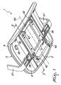
Figure 1 a perspective view from below of a seat according to the invention; -
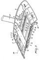
Figure 2 is a perspective view and cross-section view of the seat ofFigure 1 in which an alternative form of the padding is indicated by a dotted line; -
Figure 3 is a plan view from below of the seat ofFigure 1 in which an alternative form of the padding is indicated by a dotted line; -
Figure 4 is a perspective view and exploded view of a seat according to the invention; -
Figure 5 is a perspective view and sectional view along the revered plane ofFigure 1 of the load-bearing structure of the seat according to the invention; -
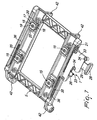
Figure 6 is an overhead perspective view of the load-bearing structure of the seat according to the invention without the seat surface; -
Figure 7 is an overhead perspective view of the support body of the load-bearing structure of the seat according to the invention; -
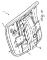
Figures 8 ,9 and10 show in perspective from below the seat according to the invention connected to three different tilt adjustment devices are compatible with the frame of a chair or armchair. - With reference to these figures,
reference numeral 1 is used to broadly indicate a seat for chairs or armchairs in particular, reclining office type. - In the present specification, the term "seat" is used to indicate all elements which define the support plane of a chair or armchair and which, in general, is paired to a backrest and, optionally, armrests.
- In embodiments, the
seat 1 comprises a load-bearingstructure 2, a removabletype seat surface 3 which overlaps the load-bearingstructure 2 and a connection means 4 to couple theseat surface 3 to the load-bearingstructure 2. - The load-bearing
structure 2 is compatible with the frame of a chair or armchair, in particular to the pedestal of an office chair (not shown in the detail). - The load-bearing
structure 2 includes asupport body 5 which is compatible with the frame of the chair or armchair and a load-bearingbase 6 to which theseat surface 3 is connected. - The load-bearing
base 6 is slidingly paired to thesupport body 5 along itslongitudinal axis 6A, and is provided with astop means 7 for supporting sliding of the load-bearingbase 6 relative to thesupport body 5. - The
seat surface 3 is formed with apadding support panel 8 and at least onepadding layer 9 firmly connected to thesupport panel 8. - The
padding layer 9 is affixed to thesupport panel 8 by bonding or comolding so as to form a single body, though other connecting schemes can be envisioned. - In one embodiment, the connection means 4 which removably join the
seat surface 3 to the load-bearingstructure 2, are of a quick release type. Specifically, the connecting means is formed by pairs oftabs 10 which overhanging the side of the load-bearingbase 6 turned toward thesupport panel 8, and each of which is provided with aretaining tooth 11. The pairs oftabs 10 are quick release insertible within thecorresponding seats 12 defined in thesupport plane 8, or vice-versa. - Other ways of forming the removable type connection means 4 and in particular quick release type capable of allowing the removal of the
internal seat surface 3 from the load-bearingstructure 2, may be envisioned, for example by replacing theseat surface 3 with one of a different design. - In one embodiment of the
seat 1, the radial dimensions of the load-bearingstructure 2, in a plan view, is smaller and is contained within the radial dimension of the seat surface (seeFigure 3 ). In particular, the radial dimension of the load-bearingbase 6, which substantially has the form of a plate, is less and is contained within the radial dimension of thepadding layer 9 which wraps around the perimeter edge of thesupport panel 8. Also, the radial dimension of thesupport body 5, which also substantially has the form of a plate, is less and is contained within the radial dimension of the load-bearingbase 6. - Advantageously, the profile of the
seat surface 3 is linked to the profile of the load-bearingstructure 2, as shown inFigure 2 . In particular, the profile of the portion ofpadding layer 9 what wraps around the perimeter edge of thesupport panel 8 connects and continues the course of the profile of the load-bearingbase 6. -
Figures 2 and3 show, in a continuous line one embodiment of theseat surface 3 and in particular of thepadding layer 9 and, in a dotted line, another embodiment thereof, wider and of a different configuration respectively. - Maintaining the load-bearing
structure 2 unchanged enables the replacement of theseat surface 3 to produce seats of different design according to different needs. Thedifferent seat surfaces 3 differ by the different design of thepadding layer 9, and the possibly (though riot necessarily) by the shape of thesupport panel 8. Replacement of theseat surface 3 is simple and easy due to the removable type connection means 4 and in particular of quick release type that affixes theseat surface 3 to the load-bearingstructure 2. - The load-bearing
base 6, to which theseat surface 3 is firmly connected and removable, is slidingly paired to thesupport body 5 alonglongitudinal axis 6A. In the embodiment represented in the drawing figures, the load-bearingbase 6 has a pair of machined rectilinear guides parallel tolongitudinal axis 6A each of which is formed as agroove 13 along which are longitudinally machinedbuttonholes 14. Inside each rectilinear track there is slidingly housed in both directions at least onerunner 15 fastened to thesupport body 5. - Between each
runner 15 and the respective rectilinear track is defined a form connection that prevents reciprocal detachment along the transversal directions toaxis 6A, theskids 15 thus acting as transfer elements for the load-bearingbase 6 on thesupport body 5. - In one embodiment, each
runner 15 comprises anut 16 which has one end affixed to the side of thesupport body 5 facing the load-bearingbase 6 and which extends through therespective buttonhole 14. At the opposite end of thenut 16 there is formed ahead 17, which widens to the sides of thebuttonhole 14 so as to define said form connection. - The
runner 15 is fastened to thesupport body 5 with ascrew 18 or other fastener that passes through the thickness of thesupport body 5 to engage anut 19 housed in a cavity machined in thehead 17. Eachrunner 15 is formed by one or moreflexible tabs 20 machined from one or both of its opposite ends, along the slide path.Flexible tabs 20 extend from the opposite ends ofhead 17 of eachrunner 15. - Stop means 7 of the sliding of the load-bearing
base 6 relative to thesupport body 5 includes at least onerack 21, which is machined in thesupport body 5 and extends in a parallel direction to thelongitudinal axis 6A, and anengagement element 22 formed by one or more stop teeth cooperating with therack 21 and which is paired to the load-bearingbase 6. -
Engagement element 22 is movably paired to the load-bearingbase 6 between an engaged configuration and a release or disengagement configuration with therack 21, elastic thrust means being provided, comprising aspring 23, capable of maintaining theengagement element 22 in the engaged configuration. - In the engaged configuration, the stop teeth are engaged with the
rack 21 to block the sliding of the load-bearingbase 6 relative to thesupport body 5. In the release configuration, the stop teeth are disengaged from therack 21 to release the sliding of the load-bearingbase 6 relative to thesupport body 5. - The stop means 7 also includes a push-button device for controlling movement of the
engagement element 22 between the two configurations. Such a push-button device is formed by apin 24 that is provided parallel to therack 21 and which is rotatively supported around its own axis by a pair offirst supports 25 machined in the load-bearingbase 6. Theengagement element 22 is fastened in overhang to thepin 24. - A
bracket 26 protrudes from thepin 24 in a direction opposite to theengagement element 22 and defines a comparison surface for thespring 23. - At the opposite end of the
pin 24 is defined afurther bracket 27 on which leverage is applied for controlling the rotation of thepin 24 and which is provided with adrive button 28. Such leverage is applied via alever 29 pivotable around thearticulation pin 30 which is parallel to thepin 24, and which is rotatively supported by a pair ofcorresponding supports 31 machined on the load-bearing base 6. One end of thelever 29 acts on thebracket 27, the opposite end being provided with thedrive button 28 housed in a correspondingaperture 32 machined in the load-bearing base 6 and from which it protrudes below. - A
cover 33, fastened using thescrews 34 to the load-bearing base 6, holds the various elements of the stop means 7 in their corresponding seats. - Acting on the
drive button 28 causes the rotation of thepin 24 in opposition to the thrust action of the spring 23 (counterclockwise in the figures) and, therefore, the release of theengagement element 22 from therack 21. This facilitates sliding of the load-bearing base and as a consequence theseat surface 3 firmly connected to it, relative to thesupport body 5 to be able to adjust its position alongaxis 6A. - Between the load-
bearing base 6 and thesupport body 5, return elastic bodies act, which in the depicted embodiment comprise one or more traction springs 35. The one or more traction springs 35 act in parallel to theaxis 6A, and each has opposite ends hooked to the load-bearing base 6 and to thesupport body 5, respectively. Eachtraction spring 35 is enclosed between arespective housing containment 36 machined in thesupport body 5, thus remaining hidden and inaccessible to a user. - In one embodiment,
seat 1 includes one or twosupport arms 37 of a respective armrest which are removably paired to the load-bearing structure 2. In particular, the load-bearing structure 2 is formed by acrossbrace 38 of the load-bearing base 6 connected to the upper side of the load-bearing base 6. Eacharm 37 is L-shaped and has a leg which rests on the lower surface of the load-bearing baste 6 and the other leg that extends upward and next to the load-bearing base 6. - The L-shaped leg that rests on the lower surface of the load-
bearing base 6 is provided with holes through which screws 39 or other fasteners pass through the load-bearing base 6. Thescrews 39 engage in corresponding holes machined at the opposite ends of thecrossbrace 38. In this way, thearms 37 and thecrossbrace 38 are affixed to the load-bearing base 6. - The
support body 5 can be connected below with atilt control device 40 ofseat 1. -
Figures 8 ,9 and.10 show seat 1 connected to different types of thecontrol device 40 not illustrated in detail for sake of clarity and as they are of a well known type. - Each of these
adjustment devices 40 is provided with aconnection seat 41 for the rod or support pedestal of a chair. - In one embodiment, the
support body 5 contains one or more.pairs ofears 42 that protrude there below, each of which is provided with an eye for the articulation with thecontrol device 40. - In operation, load-
bearing structure 2, inparticular support body 5 of the same, is affixed to the frame or a chair or armchair directly or, possibly, using atilt control device 40. In the event a chair occupant wishes to change the position of theseat surface 3, it is sufficient to press thedrive button 28 to release thestop element 22 from therack 21 and to free the relative axial sliding of theseat surface 3 relative to the load-bearing structure 2. By releasingdrive button 28, stopelement 22, thrust by the reaction of thespring 23, returns to an engaged configuration with therack 21, blocking theseat surface 3 in the desired position. Thesprings 35 insure the return of theseat surface 3 at the beginning of the adjustment travel. - In case it is necessary to replace the
seat surface 3, for example with one having different dimensions, shape or design, it is sufficient to detach it from the load-bearing structure 2 and to attach it to a new ordifferent seat surface 3. The execution of the operations replacing theseat surface 3 is simple and quick due to the providing of the connection means 4 of a removable type and, particularly, quick release type. - It has been shown in practice how various embodiments the of described invention achieves its aims. It should be emphasized, in particular, the fact that the seat according to the invention makes it possible to modify the shape of the seat surface according to the various market needs while unaltered load-bearing structure, which, consequently, brings about a reduction of the costs for producing various chairs as well as less waste of material.
- The seat according to the invention also permits simple and safe adjustment of the seat surface, all components of the control device, including the return springs, recessed/encased in the load-bearing structure and inaccessible to a user, with the exception of the drive button.
- Finally, the seat according to the invention is versatile allowing it to be equipped with different types of adjustment devices in a simple fashion.
- The thus conceived invention is subject to many modifications and variations all of which fall within the scope of the inventive concept. Also all details can be replaced by other technically equivalent details. In practice, the materials used, as well as the forms and dimensions can be any of those according to the needs without falling outside the scope of protection of the following claims.
Claims (19)
- A seat (1) for chairs or armchairs, characterized in that it comprises a load-bearing structure (2) compatible with the frame of a chair or armchair, a seat surface (3) overlapping said load-bearing structure and connection means (4) to couple a removable type of said seat surface (3) to said load-bearing structure (2), characterized in that said load-bearing structure (2) comprises at least one support arm (37) for an armrest.
- A seat (1) according to Claim 1, characterized in that, seen in a plan view, the radial dimension of said load-bearing structure (2) is smaller and is contained inside the radial dimension of said seat surface (3).
- A seat (1) according to Claim 1, characterized in that said removable connection means (4) are of the quick release type.
- A seat (1) according to Claim 3, characterized in that said removable and quick release connection means (4) comprise at least one tab (10) defined as overhanging the side of said load-bearing structure (2) turned toward said seat surface (3) and provided with at least one retaining tooth (11) which can be inserted for quick release in a corresponding seat (12) defined in the side of said seat surface (3) turned toward said load-bearing structure (2) or vice-versa.
- A seat (1) according to Claim 4, characterized in that a plurality of said tabs (10) are provided in pairs.
- A seat (1) according to Claim 1, characterized in that said seat surface (3) comprises a support panel (8) and at least one padding layer (9) which is firmly connected to said support panel (8).
- A seat (1) according to Claim 1, characterized in that said seat surface (3) has a profile which connects to the profile of said load-bearing structure (2).
- A seat (1) according to Claim 1, characterized in that said load-bearing structure (2) comprises a support body (5) compatible with said frame and a load-bearing base (6) on which said seat surface is connected and which is slidingly paired to said support body (5) along its longitudinal axis (6A), said load-bearing base (6) being provided with a stop means (7) for supporting the sliding of said load-bearing base (6) relative to said support body (5).
- A seat (1) according to Claim 8, characterized in that said load-bearing base (6) comprises at least one track rectilinear and parallel to said longitudinal axis (6A) which is defined on the one hand between said support body (5) and said load-bearing base (6) and at least one runner (15) which is slidingly housed in said guide and which is define on the other hand between said support body (5) and said load-bearing base (6), between said runner (15) and said guide being defined a form connection which prevents separation along the transverse direction to said longitudinal axis (6A).
- A seat (1) according to Claim 9, characterized in that said runner (15) comprises at least one flexible tab (20) defined by at least one of the two opposite ends, considered in the sliding direction.
- A seat (1) according to Claim 9, characterized in that said guide comprises at least one groove (13) defined in said load-bearing base (6) in a direction parallel to said longitudinal axis (6A) and at least one buttonhole (14) defined along said groove (13) and by the fact that said runner (15) comprises a rod which is fastened to said support body (5) and which extends through said buttonhole (14), and a head (17), which is fastened to the free end of said rod and which widens at the sides of said buttonhole (14) thus defining said form connection.
- A seat (1) according to Claim 8, characterized in that said stop means (7) comprise at least one rack (21) parallel to said longitudinal axis (6A) and firmly affixed to one of said support body (5) and said load-bearing base (6) and at least one pawl (22) which is paired movably to the other between said support body (5) and said load-bearing base (6) between an engaged configuration, in which said pawl (22) engages with said rack (21) for blocking of the sliding of said load-bearing base (6) relative to said support body (5), and a release configuration, in which said pawl (22) is disengaged by said rack (21) for the release of the sliding of said load-bearing base (6) relative to said support body (5), said pawl (22) being held in said engaged configuration by elastic thrust means (23).
- A seat (1) according to Claim 12, characterized in that said pawl (22) is paired to a push button device that controls its motion from said engaged configuration to said release configuration contrary to said elastic thrust means (23).
- A seat (1) according to Claim 13, characterized in that said push button device comprises a pin (24) that is rotatively mounted around its longitudinal axis and which is provided parallel to said rack (21) and to which is fastened in overhang at least one pawl (22), a bracket (26) which protrudes from said pin (24) in the opposed direction to said pawl (22) and on which act said elastic thrust means (23) and a leverage that controls the rotation of said pin (24) and which is provided with a drive button (28).
- A seat (1) according to Claim 8, characterized in that it comprises return elastic bodies acting between said support body (5) and said load-bearing base (6).
- A seat (1) according to Claim 15, characterized in that said return elastic bodies comprise at least one traction spring (35) which acts parallel to said longitudinal axis (6A) and whose opposite ends are hooked to said support body (5) and said load-bearing base (6), respectively, at least one between said support body (5) and said load-bearing base (6) comprising at least one housing containment (36) of said traction spring (35).
- A seat (1) according to Claim 1, characterized in that said load-bearing structure (2) comprises a crossbrace (38) of said load-bearing base (6) to which is anchored at least one support arm (37).
- A seat (1) according to Claim 1, characterized in that it comprises a tilt control device (40) which is fastened to said load-bearing structure (2) and which is compatible with said frame.
- A seat (1) according to Claim 18; characterized in that said support body (5) comprises mounting means to said tilt control device (40).
Applications Claiming Priority (2)
| Application Number | Priority Date | Filing Date | Title |
|---|---|---|---|
| ITMI20070943 ITMI20070943A1 (en) | 2007-05-09 | 2007-05-09 | SEAT FOR CHAIRS OR ARMCHAIRS PARTICULARLY OF ADJUSTABLE OFFICE TYPE. |
| PCT/US2008/005938 WO2008140752A1 (en) | 2007-05-09 | 2008-05-09 | Seat for chairs or armchairs particularly an adjustable office type |
Publications (3)
| Publication Number | Publication Date |
|---|---|
| EP2144537A1 EP2144537A1 (en) | 2010-01-20 |
| EP2144537A4 EP2144537A4 (en) | 2011-07-27 |
| EP2144537B1 true EP2144537B1 (en) | 2012-08-01 |
Family
ID=40002546
Family Applications (1)
| Application Number | Title | Priority Date | Filing Date |
|---|---|---|---|
| EP08754285A Not-in-force EP2144537B1 (en) | 2007-05-09 | 2008-05-09 | Seat for chairs or armchairs particularly an adjustable office type |
Country Status (3)
| Country | Link |
|---|---|
| EP (1) | EP2144537B1 (en) |
| IT (1) | ITMI20070943A1 (en) |
| WO (1) | WO2008140752A1 (en) |
Families Citing this family (3)
| Publication number | Priority date | Publication date | Assignee | Title |
|---|---|---|---|---|
| EP2434927B1 (en) | 2009-05-27 | 2016-08-17 | Steelcase Inc. | Mechanism for horizontally sliding the seat portion of a seat |
| IT1395525B1 (en) | 2009-09-03 | 2012-09-28 | Arper Spa | SEAT ELEMENT |
| DE102012006687B4 (en) * | 2012-03-31 | 2022-12-29 | Adient Us Llc | vehicle seat |
Family Cites Families (9)
| Publication number | Priority date | Publication date | Assignee | Title |
|---|---|---|---|---|
| GB599981A (en) * | 1945-09-27 | 1948-03-25 | Birmingham Guild Ltd | Improvements in chairs and other seats |
| US3823980A (en) * | 1973-05-14 | 1974-07-16 | Blair Mfg Co | Chair |
| US3851920A (en) * | 1973-07-23 | 1974-12-03 | All Steel Inc | Shell chair construction |
| US5820221A (en) * | 1996-09-25 | 1998-10-13 | Tempress, Inc. | Foldable seat having removable panels |
| AU2007200895B2 (en) * | 2000-03-02 | 2009-04-23 | Camatic Pty Ltd | Improved Theatre Chair |
| US6499801B1 (en) * | 2000-03-03 | 2002-12-31 | Steelcase Development Corporation | Chair having removable cover and cushion |
| GB0010238D0 (en) * | 2000-04-28 | 2000-06-14 | Northeastern Components Intern | Locking mechanism for chair and pushbutton control therefor |
| US6842959B2 (en) * | 2001-01-25 | 2005-01-18 | Dahti, Inc. | Load bearing fabric attachment and associated method |
| US7159942B2 (en) * | 2004-08-26 | 2007-01-09 | L & P Property Management Company | Seat slide adjustment mechanism |
-
2007
- 2007-05-09 IT ITMI20070943 patent/ITMI20070943A1/en unknown
-
2008
- 2008-05-09 WO PCT/US2008/005938 patent/WO2008140752A1/en not_active Ceased
- 2008-05-09 EP EP08754285A patent/EP2144537B1/en not_active Not-in-force
Also Published As
| Publication number | Publication date |
|---|---|
| ITMI20070943A1 (en) | 2008-11-10 |
| EP2144537A1 (en) | 2010-01-20 |
| EP2144537A4 (en) | 2011-07-27 |
| WO2008140752A1 (en) | 2008-11-20 |
Similar Documents
| Publication | Publication Date | Title |
|---|---|---|
| US8662591B2 (en) | Reclining chair headrest with height adjustment mechanism | |
| CN101522075B (en) | Reclining chair with enhanced adjustability | |
| EP2282656B1 (en) | Armrest apparatus | |
| US7080885B2 (en) | Task chair | |
| US7500718B2 (en) | Tilt tension mechanism for chair | |
| US8696064B2 (en) | Backrest inclination structure for lumbar support | |
| US11284724B2 (en) | Furniture member having lumbar adjustment mechanism | |
| ES2219609T3 (en) | SEAT FURNITURE ARTICLE. | |
| WO2008140752A1 (en) | Seat for chairs or armchairs particularly an adjustable office type | |
| US5464269A (en) | Upholstered furniture and movable headrest | |
| US20170273462A1 (en) | Back Adjusting and Positioning Structure of Chair | |
| CN201384260Y (en) | Chair cushion capable of being adjusted forwards and backwards | |
| JP3989765B2 (en) | Gas spring for chair | |
| JP4936270B2 (en) | Chair | |
| JP2002119347A (en) | Chair | |
| EP4420561A1 (en) | Armrest structure for a chair, and chair with armrest structure | |
| JP2000050996A (en) | Chair and turntable therefor | |
| KR101722316B1 (en) | Chair of Move Back | |
| CN119732565A (en) | Chair | |
| CN121730592A (en) | Backrest adjustment and adaptive mechanism and seat | |
| KR200367066Y1 (en) | Office chairs | |
| JP2017086370A (en) | Chair | |
| JP2025059579A (en) | Armrests and chairs | |
| JP2007190220A (en) | Connecting structure of armpit | |
| CN114190723A (en) | Zero gravity leisure sofa of strenghthened type upgrades |
Legal Events
| Date | Code | Title | Description |
|---|---|---|---|
| PUAI | Public reference made under article 153(3) epc to a published international application that has entered the european phase |
Free format text: ORIGINAL CODE: 0009012 |
|
| 17P | Request for examination filed |
Effective date: 20091116 |
|
| AK | Designated contracting states |
Kind code of ref document: A1 Designated state(s): AT BE BG CH CY CZ DE DK EE ES FI FR GB GR HR HU IE IS IT LI LT LU LV MC MT NL NO PL PT RO SE SI SK TR |
|
| AX | Request for extension of the european patent |
Extension state: AL BA MK RS |
|
| DAX | Request for extension of the european patent (deleted) | ||
| A4 | Supplementary search report drawn up and despatched |
Effective date: 20110628 |
|
| GRAP | Despatch of communication of intention to grant a patent |
Free format text: ORIGINAL CODE: EPIDOSNIGR1 |
|
| GRAC | Information related to communication of intention to grant a patent modified |
Free format text: ORIGINAL CODE: EPIDOSCIGR1 |
|
| RIN1 | Information on inventor provided before grant (corrected) |
Inventor name: SLONGO, ALESSANDRO Inventor name: COSTAGLIA, MASSIMO |
|
| GRAS | Grant fee paid |
Free format text: ORIGINAL CODE: EPIDOSNIGR3 |
|
| RIN1 | Information on inventor provided before grant (corrected) |
Inventor name: SLONGO, ALESSANDRO Inventor name: COSTAGLIA, MASSIMO |
|
| GRAA | (expected) grant |
Free format text: ORIGINAL CODE: 0009210 |
|
| AK | Designated contracting states |
Kind code of ref document: B1 Designated state(s): AT BE BG CH CY CZ DE DK EE ES FI FR GB GR HR HU IE IS IT LI LT LU LV MC MT NL NO PL PT RO SE SI SK TR |
|
| REG | Reference to a national code |
Ref country code: GB Ref legal event code: FG4D |
|
| REG | Reference to a national code |
Ref country code: CH Ref legal event code: EP Ref country code: AT Ref legal event code: REF Ref document number: 568192 Country of ref document: AT Kind code of ref document: T Effective date: 20120815 |
|
| REG | Reference to a national code |
Ref country code: IE Ref legal event code: FG4D |
|
| REG | Reference to a national code |
Ref country code: DE Ref legal event code: R096 Ref document number: 602008017617 Country of ref document: DE Effective date: 20120927 |
|
| REG | Reference to a national code |
Ref country code: NL Ref legal event code: VDEP Effective date: 20120801 |
|
| REG | Reference to a national code |
Ref country code: AT Ref legal event code: MK05 Ref document number: 568192 Country of ref document: AT Kind code of ref document: T Effective date: 20120801 |
|
| REG | Reference to a national code |
Ref country code: LT Ref legal event code: MG4D Effective date: 20120801 |
|
| PG25 | Lapsed in a contracting state [announced via postgrant information from national office to epo] |
Ref country code: LT Free format text: LAPSE BECAUSE OF FAILURE TO SUBMIT A TRANSLATION OF THE DESCRIPTION OR TO PAY THE FEE WITHIN THE PRESCRIBED TIME-LIMIT Effective date: 20120801 Ref country code: FI Free format text: LAPSE BECAUSE OF FAILURE TO SUBMIT A TRANSLATION OF THE DESCRIPTION OR TO PAY THE FEE WITHIN THE PRESCRIBED TIME-LIMIT Effective date: 20120801 Ref country code: AT Free format text: LAPSE BECAUSE OF FAILURE TO SUBMIT A TRANSLATION OF THE DESCRIPTION OR TO PAY THE FEE WITHIN THE PRESCRIBED TIME-LIMIT Effective date: 20120801 Ref country code: HR Free format text: LAPSE BECAUSE OF FAILURE TO SUBMIT A TRANSLATION OF THE DESCRIPTION OR TO PAY THE FEE WITHIN THE PRESCRIBED TIME-LIMIT Effective date: 20120801 Ref country code: CY Free format text: LAPSE BECAUSE OF FAILURE TO SUBMIT A TRANSLATION OF THE DESCRIPTION OR TO PAY THE FEE WITHIN THE PRESCRIBED TIME-LIMIT Effective date: 20120801 Ref country code: IS Free format text: LAPSE BECAUSE OF FAILURE TO SUBMIT A TRANSLATION OF THE DESCRIPTION OR TO PAY THE FEE WITHIN THE PRESCRIBED TIME-LIMIT Effective date: 20121201 Ref country code: NO Free format text: LAPSE BECAUSE OF FAILURE TO SUBMIT A TRANSLATION OF THE DESCRIPTION OR TO PAY THE FEE WITHIN THE PRESCRIBED TIME-LIMIT Effective date: 20121101 |
|
| PG25 | Lapsed in a contracting state [announced via postgrant information from national office to epo] |
Ref country code: LV Free format text: LAPSE BECAUSE OF FAILURE TO SUBMIT A TRANSLATION OF THE DESCRIPTION OR TO PAY THE FEE WITHIN THE PRESCRIBED TIME-LIMIT Effective date: 20120801 Ref country code: PT Free format text: LAPSE BECAUSE OF FAILURE TO SUBMIT A TRANSLATION OF THE DESCRIPTION OR TO PAY THE FEE WITHIN THE PRESCRIBED TIME-LIMIT Effective date: 20121203 Ref country code: SI Free format text: LAPSE BECAUSE OF FAILURE TO SUBMIT A TRANSLATION OF THE DESCRIPTION OR TO PAY THE FEE WITHIN THE PRESCRIBED TIME-LIMIT Effective date: 20120801 Ref country code: SE Free format text: LAPSE BECAUSE OF FAILURE TO SUBMIT A TRANSLATION OF THE DESCRIPTION OR TO PAY THE FEE WITHIN THE PRESCRIBED TIME-LIMIT Effective date: 20120801 Ref country code: GR Free format text: LAPSE BECAUSE OF FAILURE TO SUBMIT A TRANSLATION OF THE DESCRIPTION OR TO PAY THE FEE WITHIN THE PRESCRIBED TIME-LIMIT Effective date: 20121102 Ref country code: BE Free format text: LAPSE BECAUSE OF FAILURE TO SUBMIT A TRANSLATION OF THE DESCRIPTION OR TO PAY THE FEE WITHIN THE PRESCRIBED TIME-LIMIT Effective date: 20120801 Ref country code: PL Free format text: LAPSE BECAUSE OF FAILURE TO SUBMIT A TRANSLATION OF THE DESCRIPTION OR TO PAY THE FEE WITHIN THE PRESCRIBED TIME-LIMIT Effective date: 20120801 |
|
| PG25 | Lapsed in a contracting state [announced via postgrant information from national office to epo] |
Ref country code: NL Free format text: LAPSE BECAUSE OF FAILURE TO SUBMIT A TRANSLATION OF THE DESCRIPTION OR TO PAY THE FEE WITHIN THE PRESCRIBED TIME-LIMIT Effective date: 20120801 |
|
| PG25 | Lapsed in a contracting state [announced via postgrant information from national office to epo] |
Ref country code: DK Free format text: LAPSE BECAUSE OF FAILURE TO SUBMIT A TRANSLATION OF THE DESCRIPTION OR TO PAY THE FEE WITHIN THE PRESCRIBED TIME-LIMIT Effective date: 20120801 Ref country code: CZ Free format text: LAPSE BECAUSE OF FAILURE TO SUBMIT A TRANSLATION OF THE DESCRIPTION OR TO PAY THE FEE WITHIN THE PRESCRIBED TIME-LIMIT Effective date: 20120801 Ref country code: EE Free format text: LAPSE BECAUSE OF FAILURE TO SUBMIT A TRANSLATION OF THE DESCRIPTION OR TO PAY THE FEE WITHIN THE PRESCRIBED TIME-LIMIT Effective date: 20120801 Ref country code: RO Free format text: LAPSE BECAUSE OF FAILURE TO SUBMIT A TRANSLATION OF THE DESCRIPTION OR TO PAY THE FEE WITHIN THE PRESCRIBED TIME-LIMIT Effective date: 20120801 |
|
| PG25 | Lapsed in a contracting state [announced via postgrant information from national office to epo] |
Ref country code: IT Free format text: LAPSE BECAUSE OF FAILURE TO SUBMIT A TRANSLATION OF THE DESCRIPTION OR TO PAY THE FEE WITHIN THE PRESCRIBED TIME-LIMIT Effective date: 20120801 Ref country code: SK Free format text: LAPSE BECAUSE OF FAILURE TO SUBMIT A TRANSLATION OF THE DESCRIPTION OR TO PAY THE FEE WITHIN THE PRESCRIBED TIME-LIMIT Effective date: 20120801 |
|
| PLBE | No opposition filed within time limit |
Free format text: ORIGINAL CODE: 0009261 |
|
| STAA | Information on the status of an ep patent application or granted ep patent |
Free format text: STATUS: NO OPPOSITION FILED WITHIN TIME LIMIT |
|
| 26N | No opposition filed |
Effective date: 20130503 |
|
| PG25 | Lapsed in a contracting state [announced via postgrant information from national office to epo] |
Ref country code: BG Free format text: LAPSE BECAUSE OF FAILURE TO SUBMIT A TRANSLATION OF THE DESCRIPTION OR TO PAY THE FEE WITHIN THE PRESCRIBED TIME-LIMIT Effective date: 20121101 |
|
| REG | Reference to a national code |
Ref country code: DE Ref legal event code: R097 Ref document number: 602008017617 Country of ref document: DE Effective date: 20130503 |
|
| PG25 | Lapsed in a contracting state [announced via postgrant information from national office to epo] |
Ref country code: ES Free format text: LAPSE BECAUSE OF FAILURE TO SUBMIT A TRANSLATION OF THE DESCRIPTION OR TO PAY THE FEE WITHIN THE PRESCRIBED TIME-LIMIT Effective date: 20121112 |
|
| PG25 | Lapsed in a contracting state [announced via postgrant information from national office to epo] |
Ref country code: MC Free format text: LAPSE BECAUSE OF FAILURE TO SUBMIT A TRANSLATION OF THE DESCRIPTION OR TO PAY THE FEE WITHIN THE PRESCRIBED TIME-LIMIT Effective date: 20120801 |
|
| REG | Reference to a national code |
Ref country code: CH Ref legal event code: PL |
|
| GBPC | Gb: european patent ceased through non-payment of renewal fee |
Effective date: 20130509 |
|
| PG25 | Lapsed in a contracting state [announced via postgrant information from national office to epo] |
Ref country code: DE Free format text: LAPSE BECAUSE OF NON-PAYMENT OF DUE FEES Effective date: 20131203 Ref country code: CH Free format text: LAPSE BECAUSE OF NON-PAYMENT OF DUE FEES Effective date: 20130531 Ref country code: LI Free format text: LAPSE BECAUSE OF NON-PAYMENT OF DUE FEES Effective date: 20130531 |
|
| REG | Reference to a national code |
Ref country code: IE Ref legal event code: MM4A |
|
| REG | Reference to a national code |
Ref country code: FR Ref legal event code: ST Effective date: 20140131 |
|
| REG | Reference to a national code |
Ref country code: DE Ref legal event code: R119 Ref document number: 602008017617 Country of ref document: DE Effective date: 20131203 |
|
| PG25 | Lapsed in a contracting state [announced via postgrant information from national office to epo] |
Ref country code: GB Free format text: LAPSE BECAUSE OF NON-PAYMENT OF DUE FEES Effective date: 20130509 Ref country code: IE Free format text: LAPSE BECAUSE OF NON-PAYMENT OF DUE FEES Effective date: 20130509 |
|
| PG25 | Lapsed in a contracting state [announced via postgrant information from national office to epo] |
Ref country code: FR Free format text: LAPSE BECAUSE OF NON-PAYMENT OF DUE FEES Effective date: 20130531 |
|
| PG25 | Lapsed in a contracting state [announced via postgrant information from national office to epo] |
Ref country code: MT Free format text: LAPSE BECAUSE OF FAILURE TO SUBMIT A TRANSLATION OF THE DESCRIPTION OR TO PAY THE FEE WITHIN THE PRESCRIBED TIME-LIMIT Effective date: 20120801 |
|
| PG25 | Lapsed in a contracting state [announced via postgrant information from national office to epo] |
Ref country code: TR Free format text: LAPSE BECAUSE OF FAILURE TO SUBMIT A TRANSLATION OF THE DESCRIPTION OR TO PAY THE FEE WITHIN THE PRESCRIBED TIME-LIMIT Effective date: 20120801 |
|
| PG25 | Lapsed in a contracting state [announced via postgrant information from national office to epo] |
Ref country code: LU Free format text: LAPSE BECAUSE OF NON-PAYMENT OF DUE FEES Effective date: 20130509 Ref country code: HU Free format text: LAPSE BECAUSE OF FAILURE TO SUBMIT A TRANSLATION OF THE DESCRIPTION OR TO PAY THE FEE WITHIN THE PRESCRIBED TIME-LIMIT; INVALID AB INITIO Effective date: 20080509 |