EP2144125A1 - Liquid-Cooling Type Cooling Device and Image Forming Apparatus - Google Patents
Liquid-Cooling Type Cooling Device and Image Forming Apparatus Download PDFInfo
- Publication number
- EP2144125A1 EP2144125A1 EP20090164641 EP09164641A EP2144125A1 EP 2144125 A1 EP2144125 A1 EP 2144125A1 EP 20090164641 EP20090164641 EP 20090164641 EP 09164641 A EP09164641 A EP 09164641A EP 2144125 A1 EP2144125 A1 EP 2144125A1
- Authority
- EP
- European Patent Office
- Prior art keywords
- heat receiving
- liquid
- main body
- image forming
- heat
- Prior art date
- Legal status (The legal status is an assumption and is not a legal conclusion. Google has not performed a legal analysis and makes no representation as to the accuracy of the status listed.)
- Granted
Links
- 238000001816 cooling Methods 0.000 title claims abstract description 229
- 239000007788 liquid Substances 0.000 claims abstract description 51
- 239000002826 coolant Substances 0.000 claims abstract description 49
- 230000000630 rising effect Effects 0.000 claims abstract description 40
- 239000000463 material Substances 0.000 claims abstract description 16
- XLYOFNOQVPJJNP-UHFFFAOYSA-N water Substances O XLYOFNOQVPJJNP-UHFFFAOYSA-N 0.000 claims description 63
- 239000011347 resin Substances 0.000 claims 1
- 229920005989 resin Polymers 0.000 claims 1
- 238000010586 diagram Methods 0.000 description 12
- 238000002474 experimental method Methods 0.000 description 12
- 238000009833 condensation Methods 0.000 description 7
- 230000005494 condensation Effects 0.000 description 7
- DNIAPMSPPWPWGF-UHFFFAOYSA-N Propylene glycol Chemical group CC(O)CO DNIAPMSPPWPWGF-UHFFFAOYSA-N 0.000 description 6
- 230000002950 deficient Effects 0.000 description 5
- 238000004140 cleaning Methods 0.000 description 4
- 229920006324 polyoxymethylene Polymers 0.000 description 4
- 238000012546 transfer Methods 0.000 description 4
- 230000000007 visual effect Effects 0.000 description 4
- LYCAIKOWRPUZTN-UHFFFAOYSA-N Ethylene glycol Chemical compound OCCO LYCAIKOWRPUZTN-UHFFFAOYSA-N 0.000 description 3
- 230000005855 radiation Effects 0.000 description 3
- RYGMFSIKBFXOCR-UHFFFAOYSA-N Copper Chemical compound [Cu] RYGMFSIKBFXOCR-UHFFFAOYSA-N 0.000 description 2
- 229930182556 Polyacetal Natural products 0.000 description 2
- 238000012790 confirmation Methods 0.000 description 2
- 229910052802 copper Inorganic materials 0.000 description 2
- 239000010949 copper Substances 0.000 description 2
- 238000010438 heat treatment Methods 0.000 description 2
- 239000000203 mixture Substances 0.000 description 2
- 239000003755 preservative agent Substances 0.000 description 2
- 230000002335 preservative effect Effects 0.000 description 2
- 238000003756 stirring Methods 0.000 description 2
- 229930040373 Paraformaldehyde Natural products 0.000 description 1
- VYPSYNLAJGMNEJ-UHFFFAOYSA-N Silicium dioxide Chemical compound O=[Si]=O VYPSYNLAJGMNEJ-UHFFFAOYSA-N 0.000 description 1
- 229910052782 aluminium Inorganic materials 0.000 description 1
- XAGFODPZIPBFFR-UHFFFAOYSA-N aluminium Chemical compound [Al] XAGFODPZIPBFFR-UHFFFAOYSA-N 0.000 description 1
- 230000002528 anti-freeze Effects 0.000 description 1
- 239000007864 aqueous solution Substances 0.000 description 1
- 230000015556 catabolic process Effects 0.000 description 1
- 229910010293 ceramic material Inorganic materials 0.000 description 1
- 239000011248 coating agent Substances 0.000 description 1
- 239000004020 conductor Substances 0.000 description 1
- 238000006731 degradation reaction Methods 0.000 description 1
- 230000000694 effects Effects 0.000 description 1
- 230000007246 mechanism Effects 0.000 description 1
- 229910052751 metal Inorganic materials 0.000 description 1
- 239000002184 metal Substances 0.000 description 1
- 238000000034 method Methods 0.000 description 1
- 238000012986 modification Methods 0.000 description 1
- 230000004048 modification Effects 0.000 description 1
- -1 polyoxymethylene Polymers 0.000 description 1
- 230000008569 process Effects 0.000 description 1
- 238000010791 quenching Methods 0.000 description 1
- 230000000171 quenching effect Effects 0.000 description 1
- 239000007787 solid Substances 0.000 description 1
- 229910001220 stainless steel Inorganic materials 0.000 description 1
- 239000010935 stainless steel Substances 0.000 description 1
- 239000004094 surface-active agent Substances 0.000 description 1
Images



Classifications
-
- G—PHYSICS
- G03—PHOTOGRAPHY; CINEMATOGRAPHY; ANALOGOUS TECHNIQUES USING WAVES OTHER THAN OPTICAL WAVES; ELECTROGRAPHY; HOLOGRAPHY
- G03G—ELECTROGRAPHY; ELECTROPHOTOGRAPHY; MAGNETOGRAPHY
- G03G21/00—Arrangements not provided for by groups G03G13/00 - G03G19/00, e.g. cleaning, elimination of residual charge
- G03G21/20—Humidity or temperature control also ozone evacuation; Internal apparatus environment control
- G03G21/203—Humidity
Definitions
- the present invention generally relates to a liquid-cooling type cooling device which uses circulating liquid and an image forming apparatus using the liquid-cooling type cooling device which prevents temperature inside the image forming apparatus from being increased.
- an image forming apparatus using an electrophotographic system or an inkjet system has been well known. Many units and members whose temperature is increased corresponding to operations of the apparatus are disposed in the image forming apparatus using the electrophotographic system or the inkjet system.
- a reading unit which reads a document by radiating light on the document
- a developing device which forms a visual image by supplying toners onto the electrostatic latent image on the photoconductor body while stirring the toners, the toners which are subjected to friction by the stirring
- a fixing device which fixes the visual image transferred onto a recording medium (paper) by using heat and pressure.
- a cooling fan is used by air cooling.
- the units and the members are referred to as temperature rising parts.
- a heating value has been increased due to high-speed printing, and a heating generation density has been increased due to a small-sized apparatus. Consequently, it has been difficult for the image forming apparatus to sufficiently cool the temperature rising parts by the air cooling.
- cooling devices have been proposed in which cooling efficiency is higher than that of the cooling device by the air cooling.
- a liquid-cooling type cooling device In the liquid-cooling type cooling device, a liquid cooling medium is circulated, heat at a temperature rising part is absorbed by the liquid cooling medium at a heat receiving section, and the heat of the liquid cooling medium is radiated at a radiator.
- the cooling performance is high, and the heat can be absorbed at the heat receiving section in high efficiency. Therefore, the liquid-cooling type cooling device has been proposed to be installed in an image forming apparatus (for example, see Patent Document 1).
- a hydrophilic material is applied onto the outer surfaces of the heat receiving section (for example, see Patent Document 2).
- Patent Document 2 the size of the water droplet is prevented from being increased when the dew is condensed; however, the water droplet is not surely prevented from being dropped from the heat receiving section of the liquid-cooling type cooling device.
- a liquid-cooling type cooling device and an image forming apparatus using the liquid-cooling type cooling device in which a water droplet can be prevented from being dropped from a heat receiving section of the liquid-cooling type cooling device.
- a liquid-cooling type cooling device which cools a temperature rising part of an image forming apparatus by forming a circulating route of a liquid cooling medium.
- the liquid-cooling type cooling device includes a heat receiving section which causes the liquid cooling medium to absorb heat of the temperature rising part, a radiator which causes the heat of the liquid cooling medium to release, and a pump which circulates the liquid cooling medium.
- the heat receiving section includes a heat receiving main body in which a flowing route of the liquid cooling medium and a contacting surface for contacting the temperature rising part are formed, and a heat receiving main body covering part which covers outer surfaces other than the contacting surface of the heat receiving main body.
- the heat receiving main body covering part is formed of a material whose heat conductivity is lower than the heat conductivity of the heat receiving main body.
- a heat receiving main body covering part which covers outer surfaces other than a contacting surface to be contacted a temperature rising part of an image forming apparatus of the heat receiving main body, cover outer surfaces of the heat receiving section, and are formed of a material whose heat conductivity is lower than the heat conductivity of the heat receiving main body. Therefore, the temperature of the heat receiving main body covering part can be maintained to be higher than the temperature of the heat receiving main body.
- a temperature difference between the outer surfaces of the heat receiving section and the ambient temperature can be small. Consequently, the temperature of the outer surfaces of the heat receiving section can be prevented from being lower than a dew point temperature of atmosphere surrounding the heat receiving section, and dew condensation on the outer surfaces of the heat receiving section can be prevented. Consequently, a water droplet is prevented from being formed on the outer surfaces of the heat receiving section. Even if the water droplet is formed, since the size of the water droplet is prevented from being increased, the water droplet is prevented from being dropped from the outer surfaces of the heat receiving section.
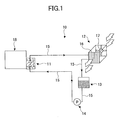
- FIG. 1 is a schematic diagram showing the structure of the liquid-cooling type cooling device 10 according to the embodiment of the present invention.
- FIG. 2 is a perspective view of a structure of a heat receiving section 11 of the liquid-cooling type cooling device 10 shown in FIG. 1 .
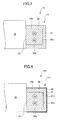
- FIG. 3 is a cross-sectional view along line I-I of FIG. 2 when the heat receiving section 11 contacts a temperature rising part 18.
- a temperature rising part 18 of an image forming apparatus is also shown.
- the liquid-cooling type cooling device 10 has a structure in which the heat receiving section 11, a radiator 12, a tank 13, and a pump (P) 14 are circularly connected by a circulating pipe 15 so that a circulating route of a liquid cooling medium is formed.
- a circulating pipe 15 As the liquid cooling medium, an antifreeze liquid is used in which the main component is propylene glycol and preservative is contained.
- the circulating pipe 15 is formed of metal such as copper and stainless steel.
- the heat receiving section 11 causes the liquid cooling medium, which circulates heat of an object to be cooled, to absorb the heat.
- the structure of the heat receiving section 11 is described below in detail.
- the liquid cooling medium absorbs the heat by passing through the heat receiving section 11 and flows to the radiator 12 via the circulating pipe 15.
- the radiator 12 includes a core part 16 having a water route whose heat releasing area is large (not shown) and a cooling fan 17 which blows air to the core part 16.
- the liquid cooling medium is cooled when the liquid cooling medium is passed through the core part 16; that is, heat is released from the liquid cooling medium.
- the radiator 12 functions as a heat releasing section in the liquid-cooling type cooling device 10.
- the liquid cooling medium passes through the radiator 12 and flows to the tank 13 via the circulating pipe 15.
- the tank 13 temporarily stores the liquid cooling medium output from the radiator 12.
- the tank 13 prevents pressure from being largely changed in the circulating route.
- the liquid cooling medium passes through the tank 13 and flows to the pump 14 via the circulating pipe 15.
- the pump 14 supplies the liquid cooling medium to the heat receiving section 11 via the circulating pipe 15.
- the liquid cooling medium is circulated in the circulating route, and the heat receiving section 11 causes the liquid cooling medium to absorb the heat and the radiator 12 causes the liquid cooling medium to release the heat. Therefore, the object to be cooled can be cooled.
- the heat receiving section 11 contacts the object to be cooled.
- the object to be cooled is the temperature rising part 18 of an image forming apparatus 50 or 501 (see FIG. 7 or 8 ) described below.
- the object to be cooled is, a reading device (not shown), a photoconductor drum 51, a developing device 54, toners (not shown), or a fixing unit 57.
- the heat receiving section 11 which contacts the temperature rising part 18 includes a heat receiving main body 20 and a heat receiving main body covering part 21.
- the heat receiving main body 20 is formed of a high heat conductive material, for example, aluminum.
- the heat receiving main body 20 has a rectangular solid shape and one of the outer surfaces of the heat receiving main body 20 is a contacting surface 22 which contacts the temperature rising part 18.
- the heat receiving main body 20 includes a flowing route 23.
- the flowing route 23 penetrates the heat receiving main body 20 to form one route so that one end 23a and the other end 23b of the flowing route 23 are adjacent to each other at one outer surface 24a of the heat receiving main body 20.
- a part extending from the one end 23a and a part extending from the other end 23b are formed in parallel along the contacting surface 22 and the extended parts are connected by a U-shaped part.
- the one end 23a is connected to one connecting route 25 and the other end 23b is connected to the other connecting route 25.
- the connecting route 25 connected to the one end 23a is connected to the circulating pipe 15 connected to the pump 14, and the connecting route 25 connected to the other end 23b is connected to the circulating pipe 15 connected to the radiator 12.
- the liquid cooling medium supplied to the heat receiving section 11 absorbs heat from the contacting surface 22 of the heat receiving main body 20 contacting the temperature rising part 18 when the liquid cooling medium passes through the flowing route 23, and the liquid cooling medium is supplied to the radiator 12.
- the flowing route 23 extends along the contacting surface 22 and has the U-shaped part.
- the number of the flowing routes and the shape of the flowing route are not limited to the above.
- the flowing route 23 is connected to the circulating pipe 15 via the connecting routes 25.
- the flowing route 23 can be connected to the circulating pipe 15.
- the heat receiving main body covering part 21 is formed to tightly cover outer surfaces 24a, 24b, 24c, 24d, and 24e of the heat receiving main body 20. That is, the heat receiving main body covering part 21 is not formed on the contacting surface 22 of the heat receiving main body 20.
- the heat receiving main body covering part 21 is formed of a material whose heat conductivity is lower than that of the heat receiving main body 20, and is formed of, for example, POM (polyoxymethylene: polyacetal).
- POM polyoxymethylene: polyacetal
- two through holes 21a for passing through the two connecting routes 25 are formed in the outer surface 24a of the heat receiving main body 20.
- the contacting surface 22 of the heat receiving main body 20 is disposed to contact the temperature rising part 18.
- the contacting surface 22 of the heat receiving main body 20 directly contacts the temperature rising part 18 in the present embodiment.
- the structure is not limited to the above.
- the liquid-cooling type cooling device 10 When an image forming apparatus using the liquid-cooling type cooling device 10 operates to form an image, the liquid-cooling type cooling device 10 operates the pump 14 based on a signal from a control device (not shown), and the liquid cooling medium is suctioned from the tank 13 to the pump 14 and is supplied to the flowing route 23 in the heat receiving section 11.
- the liquid cooling medium flowing in the flowing route 23 of the heat receiving main body 20 absorbs the heat of the temperature rising part 18 which contacts the contacting surface 22 of the heat receiving main body 20.
- the heat receiving main body 20 is formed of a high heat conductivity material, and the liquid cooling medium flowing in the flowing route 23 is sufficiently cooled by the radiator 12. Therefore, the heat receiving section 11 can absorb the heat of the temperature rising part 18 with high efficiency.
- the contacting surface 22 of the heat receiving main body 20 contacts the temperature rising part 18, and the outer surfaces 24a, 24b, 24c, 24d, and 24e of the heat receiving main body 20 other than the contacting surface 22 are covered with the heat receiving main body covering part 21. Therefore, the outer surfaces 24a, 24b, 24c, 24d, and 24e of the heat receiving main body 20 do not directly contact the outside. That is, the heat receiving main body 20 formed of the high heat conductivity material does not directly contact the ambient atmosphere. Therefore, even if the temperature of the heat receiving main body 20 falls by the liquid cooling medium flowing in the flowing route 23, dew is prevented from being condensed on the outer surfaces 24a, 24b, 24c, 24d, and 24e of the heat receiving main body 20.
- the outer surface, which contacts the surrounding ambient atmosphere is covered with the heat receiving main body covering part 21 formed of a low heat conductivity material. Therefore, even if the temperature of the heat receiving main body 20 falls when the liquid cooling medium flows in the flowing route 23, the heat receiving main body covering part 21 covering the heat receiving main body 20 prevents the temperature of the heat receiving section 11 from being lowered. Consequently, a temperature difference between the outer surface of the heat receiving main body covering part 21 (the outer surface of the heat receiving section 11) and the surrounding ambient temperature can be small.
- the temperature of the outer surface of the heat receiving section 11 can be prevented from being lower than the dew point temperature of the atmosphere at the position disposed the heat receiving section 11, and dew is prevented from being condensed on the outer surface of the heat receiving section 11. That is, water droplets are prevented from being formed on the outer surface of the heat receiving section 11 and are prevented from being dropped from the outer surface of the heat receiving section 11.
- the liquid-cooling type cooling device 10 is installed in the image forming apparatus 50 or 501 (see FIG. 7 or 8 ) whose internal humidity is likely to become high, the water droplets can be prevented from being dropped from the heat receiving section 11. Consequently, the degradation of the image quality due to blurring of the image and the stain of the paper caused by the dropping of the water droplets from the heat receiving section 11 can be prevented.
- the temperature rising part 18 of the image forming apparatus can be suitably cooled, the image forming apparatus can be suitably operated.
- the liquid-cooling type cooling device 10 can be suitably used in an image forming apparatus, for example, in a so-called high-speed apparatus, which is continuously operated for several days for printing a large number of documents in a printing office.
- the liquid-cooling type cooling device 10 is also continuously operated for a long time for cooling the temperature rising part 18 of the high-speed apparatus.
- the liquid cooling medium is continuously supplied to the heat receiving section 11 during the operation of the high-speed apparatus so that the heat at the temperature rising part 18 of the high-speed apparatus is absorbed, and the temperature of the heat receiving section 11 is maintained to be a low temperature.
- dew dew is condensed
- the size of the water droplet is likely to become large.
- FIG. 4 is a schematic diagram showing the liquid-cooling type cooling device 101.
- a high hydrophilic layer 30 to which a high hydrophilic material is applied is formed on outer surfaces of a heat receiving main body covering part 211 which covers the outer surfaces of the heat receiving main body 20 other than the contacting surface 22.
- the high hydrophilic layer 30 can be formed by applying a surface-active agent, a silica-glass coating agent, and the like onto the heat receiving main body covering part 211. That is, the high hydrophilic layer 30 is formed at parts corresponding to the outer surfaces of the heat receiving section 111 other than the contacting surface 22.
- liquid-cooling type cooling device 101 similar to in the liquid-cooling type cooling device 10, since dew is prevented from being condensed on the outer surfaces of the heat receiving section 111, even if the dew is condensed, the size of water droplets is prevented from being large, and the water droplets are prevented from being dropped from the heat receiving section 111.
- the dew point temperature in atmosphere of a position at the heat receiving section 111 becomes high, and dew is condensed on the outer surfaces of the heat receiving section 111; however, since the outer surfaces of the heat receiving section 111 are covered with the high hydrophilic layer 30, water formed by the dew condensation does not become water droplets, but becomes a water film 31 which thinly covers the outer surfaces of the heat receiving section 111.
- the water film 31 is formed on the high hydrophilic layer 30 of the heat receiving main body covering part 211 on which the dew is prevented from being condensed, the water film 31 is remarkably thin and is evaporated before the water becomes a water droplet to be dropped. Consequently, a large water droplet is prevented from being formed on the outer surfaces of the heat receiving section 111, and dropping of the water droplets is surely prevented.
- liquid-cooling type cooling device 101 even if the liquid-cooling type cooling device 101 is installed in an image forming apparatus whose inter humidity is likely to become high, dropping of the water droplets can be surely prevented from the heat receiving section 111.
- the high hydrophilic layer 30 is formed on the outer surfaces of the heat receiving main body covering part 211 by applying a high hydrophilic material.
- a high hydrophilic material it is sufficient when parts corresponding to the outer surfaces of the heat receiving section 111 are formed of a high hydrophilic material. That is, the embodiment is not limited to the modified example 1.
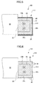
- FIG. 5 is a schematic diagram showing the liquid-cooling type cooling device 102.
- the high hydrophilic layer 30 is formed on outer surfaces of a heat receiving main body covering part 212 which covers the outer surfaces of the heat receiving main body 20 other than the contacting surface 22.
- a heat receiving section 112 provides a moisture absorbing part 32.
- the moisture absorbing part 32 is formed of a high hygroscopic material, and the material is a ceramic material whose base is a diatom earth.
- the moisture absorbing part 32 has a plate shape and is stuck on an outer surface of a heat receiving section 112 at the side of the outer surface 24e (see FIG. 2 ) of the heat receiving main body 20.
- the outer surface 24e is positioned in the gravitational force direction.
- liquid-cooling type cooling device 102 prevents dew from being condensed on the outer surfaces of the heat receiving section 112 and prevents the size of water droplets from being large, the water droplets are prevented from being dropped from the heat receiving section 112 .
- the liquid-cooling type cooling device 102 is installed in the image forming apparatus 50 or 501 (see FIG. 7 or 8 ) whose internal humidity is likely to become high, the water droplets can be surely prevented from being dropped from the heat receiving section 112.
- the moisture absorbing part 32 having the plate shape is disposed on the outer surface of the heat receiving section 112 at the downside.
- a high hygroscopic member is provided at least at a part of the outer surfaces of the heat receiving main body covering part 212. That is, the embodiment is not limited to the modified example 2.
- the moisture absorbing part 32 is provided in the heat receiving main body covering part 212 having the high hydrophilic layer 30.
- the high hydrophilic layer 30 is not always required. That is, the embodiment is not limited to the modified example 2.
- FIG. 6 is a schematic diagram showing the liquid-cooling type cooling device 103.
- plural grooves 33 are formed in outer surfaces of a heat receiving main body covering part 213 which covers the outer surfaces of the heat receiving main body 20 other than the contacting surface 22 in a heat receiving section 113.
- the depth and the width of the groove 33 is suitably determined so that the groove 33 suitably stores water formed by dew condensation on the outer surfaces of the heat receiving main body covering part 213 in the heat receiving section 113.
- the water is stored in the groove 33 by a capillary phenomenon.
- the groove 33 is preferably formed to extend in the vertical direction when the heat receiving section 113 is installed in an image forming apparatus.
- liquid-cooling type cooling device 103 prevents dew from being condensed on the outer surfaces of the heat receiving section 113 and prevents the size of water droplets from being large, the water droplets are prevented from being dropped from the heat receiving section 113.
- the dew point temperature in atmosphere of a position at the heat receiving section 113 becomes high, and dew is condensed on the outer surfaces of the heat receiving section 113; however, since the grooves 33 are formed in the outer surfaces of the heat receiving main body covering part 213 in the heat receiving section 113, water formed by the dew condensation is stored in the grooves 33 without being formed to be water droplets. Therefore, large water droplets can be prevented from being formed on the outer surfaces of the heat receiving section 113, and the water droplets can be surely prevented from being dropped from the heat receiving section 113.
- the liquid-cooling type cooling device 103 of the modified example 3 is installed in an image forming apparatus whose internal humidity is likely to become high, the water droplets can be surely prevented from being dropped from the heat receiving section 113.
- the plural grooves 33 are formed in the heat receiving main body covering part 213.
- the grooves 33 can be formed in the high hydrophilic layer 30 of the heat receiving main body covering part 211 in the modified example 1.
- the grooves 33 can be formed in the high hydrophilic layer 30 of the heat receiving main body covering part 212 in the modified example 2. That is, the embodiment of the present invention is not limited to the modified example 3.
- the liquid-cooling type cooling device 101, 102, or 103 can be installed in the image forming apparatus.
- FIG. 7 is a schematic diagram showing the image forming apparatus 50 using the liquid-cooling type cooling device 10 in the specific example 1.
- the image forming apparatus 50 includes the photoconductor drum 51, a charging device 52, a writing device 53, the developing device 54, a transferring device 55, a cleaning device 56, the fixing unit 57, and a decurler 58.
- the photoconductor drum 51 has a cylindrical shape and an electrostatic latent image is formed on the photoconductor drum 51.
- the photoconductor drum 51 rotates in the arrow direction A1 with a shaft extending in the direction perpendicular to the plane of the paper in FIG. 7 as the center by receiving a driving force from a driving mechanism (not shown).
- the charging device 52 is disposed at a position facing the photoconductor drum 51.
- the charging device 52 uniformly charges an outer surface 51a of the photoconductor drum 51 facing the charging device 52 with desirable potential by receiving electric power from a power supply device (not shown). At this time, since the photoconductor drum 51 rotates in the arrow direction A1, a part of the outer surface 51a at the downstream side from the position facing the charging device 52 is uniformly charged sequentially corresponding to the rotation of the photoconductor drum 51.
- laser beams L (or light having image information of a document such as light reflected from or transmitted through the document) are radiated from the writing device 53 onto the outer surface 51a uniformly charged by the charging device 52.
- the amount of the laser beams L is controlled based on the image information of characters and figures read from the document or image information stored beforehand.
- the electric potential (negative potential) of the outer surface 51a of the photoconductor drum 51 is lowered (the absolute potential rises to become near zero) by the radiation of the laser beams L.
- the amount of the lowering potential becomes large when the radiating amount of the laser beams L becomes large.
- the developing device 54 adheres toners to the electrostatic latent image on the outer surface 51a of the photoconductor drum 51. That is, when the outer surface 51a of the photoconductor drum 51 on which the electrostatic latent image has been formed passes through the developing device 54, an amount of toners corresponding to the electric potential distribution of the electrostatic latent image is adhered onto the outer surface 51a of the photoconductor drum 51, and a toner image having a density distribution corresponding to the electrostatic latent image is visualized (developed) on the outer surface 51a of the photoconductor drum 51.
- the transferring device 55 transfers the toner image onto a sheet (paper) S. That is, when the sheet S is transported toward the photoconductor drum 51 by a sheet transporting path 59 with predetermined timing and is passed through a position between the photoconductor drum 51 and the transferring device 55, the toner image is transferred onto the sheet S by being tightly pressed. The sheet S onto which the toner image has been transferred is transported toward the fixing unit 57 in the arrow direction A2.
- the fixing unit 57 includes a heat applying fixing roller 60 and a pressure applying roller 61.
- the toners adhered onto the sheet S are pressed on the sheet S by being sandwiched between the heat applying fixing roller 60 and the pressure applying roller 61 while being softened by heat of the heat applying fixing roller 60. With this, the toner image is fixed on the sheet S.
- the toner image fixed by the fixing unit 57 is passed through the decurler 58, a curl formed on the sheet S by the fixing unit 57 and so on is corrected and the sheet S is cooled.
- the cleaning device 56 cleans the outer surface 51a of the photoconductor drum 51 after transferring the toner image onto the sheet S. That is, after transferring the toner image onto the sheet S, the unused toners remain on the outer surface 51a of the photoconductor drum 51, and the cleaning device 56 cleans the outer surface 51a of the photoconductor drum 51 by removing the remaining toners from the outer surface 51a of the photoconductor drum 51.
- a quenching lamp (not shown) removes remaining charges on the outer surface 51a of the photoconductor drum 51.
- the image forming apparatus 50 enters a subsequent charging process waiting state.
- the liquid-cooling type cooling device 10 is used to cool the developing device 54. That is, in the specific example 1, the temperature rising part 18 of the image forming apparatus 50 is determined to be the developing device 54. In the developing device 54, friction heat is generated in toners by being stirred so that the toners obtain chargeability, and radiation heat is applied to the toners from the fixing unit 57 and so on. Consequently, the temperature of the toners rises.
- the developing device 54 is cooled so that the internal temperature of the developing device 54 is always less than a target temperature determined by the softening point temperature of the toners.
- the target temperature is determined to be less than 50 °C.
- the liquid-cooling type cooling device 10 is installed in the image forming apparatus 50 so that the contacting surface 22 of the heat receiving section 11 contacts the developing device 54.
- the other elements of the liquid-cooling type cooling device 10 are disposed at positions separated from electric circuits to be insulated, high-voltage sections, and a paper feeding tray (not shown) in the image forming apparatus 50 as much as possible.
- the high-voltage sections are the photoconductor drum 51, the charging device 52, the writing device 53, the developing device 54, the transferring device 55, the fixing unit 57, a control device (not shown), and a power supplying device (not shown).
- the radiator 12 of the liquid-cooling type cooling device 10 is disposed so that wind blown from the cooling fan 17 and passed through the core part 16 is output to the outside of the image forming apparatus 50 (the outside of a cabinet (not shown) of the image forming apparatus 50).
- the liquid-cooling type cooling device 10 can be operated corresponding to an image forming operation of the image forming apparatus 50, or can be operated corresponding the temperature of the temperature rising part 18 (the developing device 54 in the specific example 1).
- a first experiment was performed.
- the image forming apparatus 50 (Imagio Neo 750)
- double-sided printing was continuously performed for three hours at a speed of 75 sheets per one minute.
- the internal temperature of the developing device 54 was measured.
- the maximum internal temperature was 47 °C which was lower than the target temperature 50 °C determined based on the used toners.
- the toners in the developing device 54 were not found to be defective.
- water detecting sensors (not shown) were disposed at positions surrounding the heat receiving section 11 of the liquid-cooling type cooling device 10 in the image forming apparatus 50.
- the water detecting sensors did not detect water. Further, by also a visual confirmation, dropping of water droplets was not found at the positions surrounding the heat receiving section 11 and a water droplet was not formed on the outer surfaces of the heat receiving section 11.
- the liquid-cooling type cooling device 10 is applied to the developing device 54 in the image forming apparatus 50 as the temperature rising part 18.
- the liquid-cooling type cooling device 10 can be applied to other elements in the image forming apparatus 50 as the temperature rising part 18.
- the liquid-cooling type cooling device 10' is described below.
- the liquid-cooling type cooling device 10' is a device modified from the liquid-cooling type cooling device 10.
- liquid-cooling type cooling device 10 instead of installing the liquid-cooling type cooling device 10', a liquid-cooling type cooling device 101', 102', or 103' modified from the liquid-cooling type cooling device 101, 102, or 103 can be installed in the image forming apparatus.
- FIG. 8 is a schematic diagram showing an image forming apparatus 501 using the liquid-cooling type cooling device 10' in the specific example 2.
- the image forming apparatus 501 includes four image forming devices 62(BK) for black, 62(C) for cyan, 62(M) for magenta, and 62(Y) for yellow; an intermediate transfer belt 63, the transferring device 55, the fixing unit 57, and the decurler 58.
- the transferring device 55, the fixing unit 57, and the decurler 58 are the same as those in the image forming apparatus 50 shown in FIG. 7 . Therefore, the same description is omitted.
- the image forming devices 62 represents the four image forming devices 62(BK) for black, 62(C) for cyan, 62(M) for magenta, and 62(Y) for yellow.
- each of the four image forming devices 62 the photoconductor drum 51, the charging device 52, the writing device 53, the developing device 54, and the cleaning device 56 are provided.
- an electrostatic latent image is formed on the photoconductor drum 51, and a toner image is formed on the photoconductor drum 51.
- the toner images formed on the corresponding photoconductor drums 51 are transferred onto the intermediate transfer belt 63 (image carrier).
- the toner images transferred onto the intermediate transfer belt 63 are transferred onto a sheet S transported by the sheet transporting path 59 by the transferring devices 55.
- the toner images transferred onto the sheet S are fixed on the sheet S by the fixing unit 57. With this, a color image is formed on the sheet S.
- the liquid-cooling type cooling device 10' is used to cool the developing device 54 in each of the image forming devices 62. That is, in the specific example 2, the temperature rising parts 18 of the image forming apparatus 501 are determined to be the developing devices 54 of the image forming devices 62. In the image forming apparatus 501 of the specific example 2, the target temperature of the internal temperature of the developing device 54 is determined to be less than 45 °C from a viewpoint of the softening point temperature of the used toners.
- the four heat receiving sections 11 are connected in series by the circulating pipe 15.
- the contacting surface 22 of the heat receiving section 11 contacts the developing device 54 in each of the four image forming devices 62 in the image forming apparatus 501.
- the heat receiving main body 20 is formed of copper and the heat receiving main body covering part 21 is formed of polyacetal.
- an aqueous solution is used in which a mixture of ethylene glycol and propylene glycol is the main component and preservative is contained in the mixture.
- the internal temperature of the developing device 54 in each of the image forming devices 62 was measured.
- the maximum internal temperature was 42 to 44 °C which was lower than the target temperature 45 °C determined based on the used toners.
- the toners in the developing devices 54 were not found to be defective.
- water detecting sensors (not shown) were disposed at positions surrounding each of the heat receiving sections 11 of the liquid-cooling type cooling device 10' in the image forming apparatus 501.
- the water detecting sensors did not detect water.
- dropping of water droplets was not found at the positions surrounding each of the heat receiving sections 11 and a water droplet was not formed on the outer surfaces of each of the heat receiving section 11.
- the liquid-cooling type cooling device 10' is applied to the developing device 54 in the image forming apparatus 501 as the temperature rising part 18.
- the liquid-cooling type cooling device 10' can be applied to other elements in the image forming apparatus 501 as the temperature rising part 18.
- the liquid-cooling type cooling device 10 (10') is applied to the image forming apparatus 50 (501) of the electrophotographic system.
- the present embodiment can be applied to an image forming apparatus which has a unit or a member whose temperature rises when the apparatus is operated. That is, the present embodiment can be applied to, for example, an image forming apparatus of an inkjet system.
- the shape of the heat receiving section 11 is rectangular and the contacting surface 22 is a flat surface.
- the liquid-cooling type cooling device 10 (10') can cool the temperature rising part 18 of the image forming apparatus 50 (501)
- the shape of the heat receiving section 11 is not limited to rectangular and the contacting surface 22 is not limited to the flat surface.
Landscapes
- Life Sciences & Earth Sciences (AREA)
- Engineering & Computer Science (AREA)
- Atmospheric Sciences (AREA)
- Biodiversity & Conservation Biology (AREA)
- Ecology (AREA)
- Environmental & Geological Engineering (AREA)
- Environmental Sciences (AREA)
- Physics & Mathematics (AREA)
- General Physics & Mathematics (AREA)
- Control Or Security For Electrophotography (AREA)
Abstract
Description
- The present invention generally relates to a liquid-cooling type cooling device which uses circulating liquid and an image forming apparatus using the liquid-cooling type cooling device which prevents temperature inside the image forming apparatus from being increased.
- Recently, as image forming apparatuses such as a printer, a facsimile machine, and a multifunctional apparatus including a printing function and a facsimile transmitting function, an image forming apparatus using an electrophotographic system or an inkjet system has been well known. Many units and members whose temperature is increased corresponding to operations of the apparatus are disposed in the image forming apparatus using the electrophotographic system or the inkjet system. As the units and the members whose temperature is increased in an image forming apparatus using the electrophotographic system, for example, there are, a reading unit which reads a document by radiating light on the document, a photoconductor body on which an electrostatic latent image is formed by a writing unit, a developing device which forms a visual image by supplying toners onto the electrostatic latent image on the photoconductor body while stirring the toners, the toners which are subjected to friction by the stirring, and a fixing device which fixes the visual image transferred onto a recording medium (paper) by using heat and pressure.
- When the temperature rises, some functions do not operate well in the image forming apparatus. Therefore, generally, in order to cool a temperature risen unit or member, a cooling fan is used by air cooling. Hereinafter, in some cases, the units and the members are referred to as temperature rising parts. However, recently, in the image forming apparatus, a heating value has been increased due to high-speed printing, and a heating generation density has been increased due to a small-sized apparatus. Consequently, it has been difficult for the image forming apparatus to sufficiently cool the temperature rising parts by the air cooling.
- In order to solve the above problem, cooling devices have been proposed in which cooling efficiency is higher than that of the cooling device by the air cooling. As one of the proposed cooling devices, there is a liquid-cooling type cooling device. In the liquid-cooling type cooling device, a liquid cooling medium is circulated, heat at a temperature rising part is absorbed by the liquid cooling medium at a heat receiving section, and the heat of the liquid cooling medium is radiated at a radiator. In the liquid-cooling type cooling device, the cooling performance is high, and the heat can be absorbed at the heat receiving section in high efficiency. Therefore, the liquid-cooling type cooling device has been proposed to be installed in an image forming apparatus (for example, see Patent Document 1).
- However, since water is evaporated from paper inside the image forming apparatus, humidity becomes higher inside the image forming apparatus than that outside the apparatus. In particular, the humidity is likely to become higher in the image forming apparatus using the liquid-cooling type cooling device than an image forming apparatus using an air-cooling type cooling device which ventilates. In the image forming apparatus using the liquid-cooling type cooling device, temperature on outer surfaces of the heat receiving section having high heat receiving efficiency becomes lower than ambient temperature inside the image forming apparatus, and the temperature on the outer surfaces of the heat receiving section becomes a dew point or less. Consequently, there is a risk that dew is condensed on the outer surfaces of the heat receiving section. When the size of a water droplet formed by the dew condensation becomes large and the water droplet drops from the heat receiving section, a part surrounding the heat receiving section is wetted. When the water droplet drops on image forming units or members such as the photoconductor body, the developing device, and the paper; the image quality is degraded due to blurring of the image or the paper may be stained.
- In order to prevent the size of the water droplet from being increased when the dew is condensed, a hydrophilic material is applied onto the outer surfaces of the heat receiving section (for example, see Patent Document 2).
- [Patent Document 1] Japanese Unexamined Patent Publication No.
2005-164927 - [Patent Document 2] Japanese Unexamined Patent Publication No.
2007-293111 - In Patent Document 2, the size of the water droplet is prevented from being increased when the dew is condensed; however, the water droplet is not surely prevented from being dropped from the heat receiving section of the liquid-cooling type cooling device.
- In a preferred embodiment of the present invention, there is provided a liquid-cooling type cooling device and an image forming apparatus using the liquid-cooling type cooling device in which a water droplet can be prevented from being dropped from a heat receiving section of the liquid-cooling type cooling device.
- Features and advantages of the present invention are set forth in the description that follows, and in part will become apparent from the description and the accompanying drawings, or may be learned by practice of the invention according to the teachings provided in the description. Features and advantages of the present invention will be realized ) and attained by a liquid-cooling type cooling device and an image forming apparatus using the liquid-cooling type cooling device particularly pointed out in the specification in such full, clear, concise, and exact terms so as to enable a person having ordinary skill in the art to practice the invention.
- To achieve one or more of these and other advantages, according to one aspect of the present invention, there is provided a liquid-cooling type cooling device which cools a temperature rising part of an image forming apparatus by forming a circulating route of a liquid cooling medium. The liquid-cooling type cooling device includes a heat receiving section which causes the liquid cooling medium to absorb heat of the temperature rising part, a radiator which causes the heat of the liquid cooling medium to release, and a pump which circulates the liquid cooling medium. The heat receiving section includes a heat receiving main body in which a flowing route of the liquid cooling medium and a contacting surface for contacting the temperature rising part are formed, and a heat receiving main body covering part which covers outer surfaces other than the contacting surface of the heat receiving main body. The heat receiving main body covering part is formed of a material whose heat conductivity is lower than the heat conductivity of the heat receiving main body.
- According to an embodiment of the present invention, in a liquid-cooling type cooling device, even if temperature of a heat receiving main body of a heat receiving section having a flowing route of a liquid cooling medium is lower than ambient temperature at a position disposed at the heat receiving section; a heat receiving main body covering part, which covers outer surfaces other than a contacting surface to be contacted a temperature rising part of an image forming apparatus of the heat receiving main body, cover outer surfaces of the heat receiving section, and are formed of a material whose heat conductivity is lower than the heat conductivity of the heat receiving main body. Therefore, the temperature of the heat receiving main body covering part can be maintained to be higher than the temperature of the heat receiving main body. That is, a temperature difference between the outer surfaces of the heat receiving section and the ambient temperature can be small. Consequently, the temperature of the outer surfaces of the heat receiving section can be prevented from being lower than a dew point temperature of atmosphere surrounding the heat receiving section, and dew condensation on the outer surfaces of the heat receiving section can be prevented. Consequently, a water droplet is prevented from being formed on the outer surfaces of the heat receiving section. Even if the water droplet is formed, since the size of the water droplet is prevented from being increased, the water droplet is prevented from being dropped from the outer surfaces of the heat receiving section.
- Features and advantages of the present invention will become more apparent from the following detailed description when read in conjunction with the accompanying drawings, in which:
-
FIG. 1 is a schematic diagram showing a structure of a liquid-cooling type cooling device according to an embodiment of the present invention; -
FIG. 2 is a perspective view of a structure of a heat receiving section of the liquid-cooling type cooling device shown inFIG. 1 ; -
FIG. 3 is a cross-sectional view along line I-I ofFIG. 2 when the heat receiving section contacts a temperature rising part of an image forming apparatus; -
FIG. 4 is a schematic diagram showing a liquid-cooling type cooling device in a modified example 1; -
FIG. 5 is a schematic diagram showing a liquid-cooling type cooling device in a modified example 2; -
FIG. 6 is a schematic diagram showing a liquid-cooling type cooling device in a modified example 3; -
FIG. 7 is a schematic diagram showing an image forming apparatus using the liquid-cooling type cooling device shown inFIGs. 1 through 3 ; and -
FIG. 8 is a schematic diagram showing another image forming apparatus using a liquid-cooling type cooling device modified from the liquid-cooling type cooling device shown inFIGs. 1 through 3 . - The best mode of carrying out the present invention is described with reference to the accompanying drawings.
- First, a structure of a liquid-cooling
type cooling device 10 according to an embodiment of the present invention is described.FIG. 1 is a schematic diagram showing the structure of the liquid-coolingtype cooling device 10 according to the embodiment of the present invention.FIG. 2 is a perspective view of a structure of aheat receiving section 11 of the liquid-coolingtype cooling device 10 shown inFIG. 1 .FIG. 3 is a cross-sectional view along line I-I ofFIG. 2 when theheat receiving section 11 contacts atemperature rising part 18. InFIG. 1 , atemperature rising part 18 of an image forming apparatus is also shown. - The liquid-cooling
type cooling device 10 has a structure in which theheat receiving section 11, aradiator 12, atank 13, and a pump (P) 14 are circularly connected by a circulatingpipe 15 so that a circulating route of a liquid cooling medium is formed. As the liquid cooling medium, an antifreeze liquid is used in which the main component is propylene glycol and preservative is contained. The circulatingpipe 15 is formed of metal such as copper and stainless steel. - The
heat receiving section 11 causes the liquid cooling medium, which circulates heat of an object to be cooled, to absorb the heat. The structure of theheat receiving section 11 is described below in detail. The liquid cooling medium absorbs the heat by passing through theheat receiving section 11 and flows to theradiator 12 via the circulatingpipe 15. - The
radiator 12 includes acore part 16 having a water route whose heat releasing area is large (not shown) and a coolingfan 17 which blows air to thecore part 16. In theradiator 12, the liquid cooling medium is cooled when the liquid cooling medium is passed through thecore part 16; that is, heat is released from the liquid cooling medium. In other words, theradiator 12 functions as a heat releasing section in the liquid-coolingtype cooling device 10. The liquid cooling medium passes through theradiator 12 and flows to thetank 13 via the circulatingpipe 15. - The
tank 13 temporarily stores the liquid cooling medium output from theradiator 12. Thetank 13 prevents pressure from being largely changed in the circulating route. The liquid cooling medium passes through thetank 13 and flows to thepump 14 via the circulatingpipe 15. - The
pump 14 supplies the liquid cooling medium to theheat receiving section 11 via the circulatingpipe 15. With this, in the liquid-coolingtype cooling device 10, the liquid cooling medium is circulated in the circulating route, and theheat receiving section 11 causes the liquid cooling medium to absorb the heat and theradiator 12 causes the liquid cooling medium to release the heat. Therefore, the object to be cooled can be cooled. - The
heat receiving section 11 contacts the object to be cooled. The object to be cooled is thetemperature rising part 18 of animage forming apparatus 50 or 501 (seeFIG. 7 or8 ) described below. InFIG. 7 , for example, the object to be cooled is, a reading device (not shown), aphotoconductor drum 51, a developingdevice 54, toners (not shown), or a fixingunit 57. - As shown in
FIGs. 2 and3 , theheat receiving section 11 which contacts thetemperature rising part 18 includes a heat receivingmain body 20 and a heat receiving mainbody covering part 21. The heat receivingmain body 20 is formed of a high heat conductive material, for example, aluminum. The heat receivingmain body 20 has a rectangular solid shape and one of the outer surfaces of the heat receivingmain body 20 is a contactingsurface 22 which contacts thetemperature rising part 18. - The heat receiving
main body 20 includes a flowingroute 23. The flowingroute 23 penetrates the heat receivingmain body 20 to form one route so that oneend 23a and theother end 23b of the flowingroute 23 are adjacent to each other at oneouter surface 24a of the heat receivingmain body 20. - That is, in the flowing
route 23, a part extending from the oneend 23a and a part extending from theother end 23b are formed in parallel along the contactingsurface 22 and the extended parts are connected by a U-shaped part. - The one
end 23a is connected to one connectingroute 25 and theother end 23b is connected to the other connectingroute 25. The connectingroute 25 connected to the oneend 23a is connected to the circulatingpipe 15 connected to thepump 14, and the connectingroute 25 connected to theother end 23b is connected to the circulatingpipe 15 connected to theradiator 12. - Therefore, the liquid cooling medium supplied to the
heat receiving section 11 absorbs heat from the contactingsurface 22 of the heat receivingmain body 20 contacting thetemperature rising part 18 when the liquid cooling medium passes through the flowingroute 23, and the liquid cooling medium is supplied to theradiator 12. - In the above, the flowing
route 23 extends along the contactingsurface 22 and has the U-shaped part. However, when the flowingroute 23 is formed by a structure in which the liquid cooling medium can efficiently absorb heat from an object to be cooled via the contactingsurface 22 of theheat receiving section 11, the number of the flowing routes and the shape of the flowing route are not limited to the above. In addition, in the above, the flowingroute 23 is connected to the circulatingpipe 15 via the connectingroutes 25. However, without using the connectingroute 25, the flowingroute 23 can be connected to the circulatingpipe 15. - The heat receiving main
body covering part 21 is formed to tightly coverouter surfaces main body 20. That is, the heat receiving mainbody covering part 21 is not formed on the contactingsurface 22 of the heat receivingmain body 20. The heat receiving mainbody covering part 21 is formed of a material whose heat conductivity is lower than that of the heat receivingmain body 20, and is formed of, for example, POM (polyoxymethylene: polyacetal). In addition, in the heat receiving mainbody covering part 21, two throughholes 21a for passing through the two connectingroutes 25 are formed in theouter surface 24a of the heat receivingmain body 20. - As shown in
FIG. 3 , in theheat receiving section 11, the contactingsurface 22 of the heat receivingmain body 20 is disposed to contact thetemperature rising part 18. The contactingsurface 22 of the heat receivingmain body 20 directly contacts thetemperature rising part 18 in the present embodiment. However, when heat of thetemperature rising part 18 is efficiently absorbed by the liquid cooling medium flowing in the flowingroute 23 of the heat receivingmain body 20, the structure is not limited to the above. - When an image forming apparatus using the liquid-cooling
type cooling device 10 operates to form an image, the liquid-coolingtype cooling device 10 operates thepump 14 based on a signal from a control device (not shown), and the liquid cooling medium is suctioned from thetank 13 to thepump 14 and is supplied to the flowingroute 23 in theheat receiving section 11. - With this, heat generated from the
temperature rising part 18 of the image forming apparatus is absorbed by the liquid cooling medium which flows in the flowingroute 23 in theheat receiving section 11, and thetemperature rising part 18 is cooled. The liquid cooling medium whose temperature has risen is supplied to theradiator 12 via the circulatingpipe 15, and the heat is released by theradiator 12. The liquid cooling medium whose heat has been released by theradiator 12 returns thetank 13 via the circulatingpipe 15. After this, the liquid cooling medium is circulated again in the circulatingpipe 15, and cools thetemperature rising part 18. - In the
heat receiving section 11, the liquid cooling medium flowing in the flowingroute 23 of the heat receivingmain body 20 absorbs the heat of thetemperature rising part 18 which contacts the contactingsurface 22 of the heat receivingmain body 20. The heat receivingmain body 20 is formed of a high heat conductivity material, and the liquid cooling medium flowing in the flowingroute 23 is sufficiently cooled by theradiator 12. Therefore, theheat receiving section 11 can absorb the heat of thetemperature rising part 18 with high efficiency. - In addition, in the
heat receiving section 11, the contactingsurface 22 of the heat receivingmain body 20 contacts thetemperature rising part 18, and theouter surfaces main body 20 other than the contactingsurface 22 are covered with the heat receiving mainbody covering part 21. Therefore, theouter surfaces main body 20 do not directly contact the outside. That is, the heat receivingmain body 20 formed of the high heat conductivity material does not directly contact the ambient atmosphere. Therefore, even if the temperature of the heat receivingmain body 20 falls by the liquid cooling medium flowing in the flowingroute 23, dew is prevented from being condensed on theouter surfaces main body 20. - In addition, in the
heat receiving section 11, the outer surface, which contacts the surrounding ambient atmosphere, is covered with the heat receiving mainbody covering part 21 formed of a low heat conductivity material. Therefore, even if the temperature of the heat receivingmain body 20 falls when the liquid cooling medium flows in the flowingroute 23, the heat receiving mainbody covering part 21 covering the heat receivingmain body 20 prevents the temperature of theheat receiving section 11 from being lowered. Consequently, a temperature difference between the outer surface of the heat receiving main body covering part 21 (the outer surface of the heat receiving section 11) and the surrounding ambient temperature can be small. - With this, the temperature of the outer surface of the
heat receiving section 11 can be prevented from being lower than the dew point temperature of the atmosphere at the position disposed theheat receiving section 11, and dew is prevented from being condensed on the outer surface of theheat receiving section 11. That is, water droplets are prevented from being formed on the outer surface of theheat receiving section 11 and are prevented from being dropped from the outer surface of theheat receiving section 11. - Therefore, even if the liquid-cooling
type cooling device 10 is installed in theimage forming apparatus 50 or 501 (seeFIG. 7 or8 ) whose internal humidity is likely to become high, the water droplets can be prevented from being dropped from theheat receiving section 11. Consequently, the degradation of the image quality due to blurring of the image and the stain of the paper caused by the dropping of the water droplets from theheat receiving section 11 can be prevented. In addition, since thetemperature rising part 18 of the image forming apparatus can be suitably cooled, the image forming apparatus can be suitably operated. - The liquid-cooling
type cooling device 10 can be suitably used in an image forming apparatus, for example, in a so-called high-speed apparatus, which is continuously operated for several days for printing a large number of documents in a printing office. - That is, since the high-seed apparatus is continuously operated for a long time, the liquid-cooling
type cooling device 10 is also continuously operated for a long time for cooling thetemperature rising part 18 of the high-speed apparatus. In theheat receiving section 11, the liquid cooling medium is continuously supplied to theheat receiving section 11 during the operation of the high-speed apparatus so that the heat at thetemperature rising part 18 of the high-speed apparatus is absorbed, and the temperature of theheat receiving section 11 is maintained to be a low temperature. In a case where dew is condensed, when the continuous operating time is long, the size of the water droplet is likely to become large. - In a conventional liquid-cooling type cooling device in which the size of the water droplets formed by the dew condensation at the heat receiving section is prevented from being large, when the continuous operating time becomes large in the high-speed apparatus, the amount of the water droplets formed at the outer surface of the heat receiving section is increased; consequently, there is a risk that dropping of the water droplets is generated. However, in the liquid-cooling
type cooling device 10 according to the present embodiment, since the dew condensation itself is prevented at theheat receiving section 11, regardless of the length of the continuous operating time, the water droplets can be prevented from being dropped. - Next, a liquid-cooling
type cooling device 101 of a modified example 1 according to the embodiment of the present invention is described. The basic structure of the liquid-coolingtype cooling device 101 is the same as that of the liquid-coolingtype cooling device 10. Therefore, in the modified example 1 shown inFIG. 4 , when an element is similar to or the same as that of the liquid-coolingtype cooling device 10 shown inFIGs. 1 through 3 , the same reference number as that shown inFIGs. 1 through 3 is used, and the same description as that shown inFIGs. 1 through 3 is omitted.FIG. 4 is a schematic diagram showing the liquid-coolingtype cooling device 101. - As shown in
FIG. 4 , in the liquid-coolingtype cooling device 101, a highhydrophilic layer 30 to which a high hydrophilic material is applied is formed on outer surfaces of a heat receiving mainbody covering part 211 which covers the outer surfaces of the heat receivingmain body 20 other than the contactingsurface 22. The highhydrophilic layer 30 can be formed by applying a surface-active agent, a silica-glass coating agent, and the like onto the heat receiving mainbody covering part 211. That is, the highhydrophilic layer 30 is formed at parts corresponding to the outer surfaces of theheat receiving section 111 other than the contactingsurface 22. - In the liquid-cooling
type cooling device 101, similar to in the liquid-coolingtype cooling device 10, since dew is prevented from being condensed on the outer surfaces of theheat receiving section 111, even if the dew is condensed, the size of water droplets is prevented from being large, and the water droplets are prevented from being dropped from theheat receiving section 111. - In addition, in the liquid-cooling
type cooling device 101, when the humidity in theimage forming apparatus 50 or 501 (seeFIG. 7 orFIG. 8 ) having the liquid-coolingtype cooling device 101 becomes remarkably high, the dew point temperature in atmosphere of a position at theheat receiving section 111 becomes high, and dew is condensed on the outer surfaces of theheat receiving section 111; however, since the outer surfaces of theheat receiving section 111 are covered with the highhydrophilic layer 30, water formed by the dew condensation does not become water droplets, but becomes awater film 31 which thinly covers the outer surfaces of theheat receiving section 111. - Since the
water film 31 is formed on the highhydrophilic layer 30 of the heat receiving mainbody covering part 211 on which the dew is prevented from being condensed, thewater film 31 is remarkably thin and is evaporated before the water becomes a water droplet to be dropped. Consequently, a large water droplet is prevented from being formed on the outer surfaces of theheat receiving section 111, and dropping of the water droplets is surely prevented. - As described above, in the liquid-cooling
type cooling device 101, even if the liquid-coolingtype cooling device 101 is installed in an image forming apparatus whose inter humidity is likely to become high, dropping of the water droplets can be surely prevented from theheat receiving section 111. - In the modified example 1, the high
hydrophilic layer 30 is formed on the outer surfaces of the heat receiving mainbody covering part 211 by applying a high hydrophilic material. However, it is sufficient when parts corresponding to the outer surfaces of theheat receiving section 111 are formed of a high hydrophilic material. That is, the embodiment is not limited to the modified example 1. - Next, a liquid-cooling
type cooling device 102 of a modified example 2 according to the embodiment of the present invention is described. The basic structure of the liquid-coolingtype cooling device 102 is the same as that of the liquid-coolingtype cooling device 101 in the modified example 1. Therefore, in the modified example 2 shown inFIG. 5 , when an element is similar to or the same as that of the liquid-coolingtype cooling device 101 shown inFIG. 4 , the same reference number as that shown inFIG. 4 is used, and the same description as that shown inFIG. 4 is omitted.FIG. 5 is a schematic diagram showing the liquid-coolingtype cooling device 102. - As shown in
FIG. 5 , in the liquid-coolingtype cooling device 102, the highhydrophilic layer 30 is formed on outer surfaces of a heat receiving mainbody covering part 212 which covers the outer surfaces of the heat receivingmain body 20 other than the contactingsurface 22. In addition to the highhydrophilic layer 30, aheat receiving section 112 provides amoisture absorbing part 32. - The
moisture absorbing part 32 is formed of a high hygroscopic material, and the material is a ceramic material whose base is a diatom earth. Themoisture absorbing part 32 has a plate shape and is stuck on an outer surface of aheat receiving section 112 at the side of theouter surface 24e (seeFIG. 2 ) of the heat receivingmain body 20. Theouter surface 24e is positioned in the gravitational force direction. - Similar to the liquid-cooling
type cooling device 10, since the liquid-coolingtype cooling device 102 prevents dew from being condensed on the outer surfaces of theheat receiving section 112 and prevents the size of water droplets from being large, the water droplets are prevented from being dropped from theheat receiving section 112 . - In addition, similar to the liquid-cooling
type cooling device 101 shown inFIG. 4 , even if dew is condensed on the outer surfaces of theheat receiving section 112, since the dew becomes thewater film 31 without forming water droplets, the water droplets is surely prevented from being dropped from theheat receiving section 112. - In addition, even if the dew is condensed on the outer surfaces of the
heat receiving section 112 of the liquid-coolingtype cooling device 102, the water droplets formed by the dew are absorbed by themoisture absorbing part 32. Therefore, large water droplets are surely prevented from being formed on the outer surfaces of theheat receiving section 112 and the water droplets are prevented from being dropped from theheat receiving section 112. - Therefore, even if the liquid-cooling
type cooling device 102 is installed in theimage forming apparatus 50 or 501 (seeFIG. 7 or8 ) whose internal humidity is likely to become high, the water droplets can be surely prevented from being dropped from theheat receiving section 112. - In the modified example 2, the
moisture absorbing part 32 having the plate shape is disposed on the outer surface of theheat receiving section 112 at the downside. However, it is sufficient when a high hygroscopic member is provided at least at a part of the outer surfaces of the heat receiving mainbody covering part 212. That is, the embodiment is not limited to the modified example 2. - In addition, in the modified example 2, the
moisture absorbing part 32 is provided in the heat receiving mainbody covering part 212 having the highhydrophilic layer 30. However, the highhydrophilic layer 30 is not always required. That is, the embodiment is not limited to the modified example 2. - Next, a liquid-cooling
type cooling device 103 of a modified example 3 according to the embodiment of the present invention is described. The basic structure of the liquid-coolingtype cooling device 103 is the same as that of the liquid-coolingtype cooling device 10 shown inFIGs. 1 through 3 in the embodiment of the present invention. Therefore, in the modified example 3 shown inFIG. 6 , when an element is similar to or the same as that of the liquid-coolingtype cooling device 10 shown inFIGs. 1 through 3 , the same reference number as that shown inFIGs. 1 through 3 is used, and the same description as that shown inFIGs. 1 through 3 is omitted.FIG. 6 is a schematic diagram showing the liquid-coolingtype cooling device 103. - As shown in
FIG. 6 , in the liquid-coolingtype cooling device 103,plural grooves 33 are formed in outer surfaces of a heat receiving mainbody covering part 213 which covers the outer surfaces of the heat receivingmain body 20 other than the contactingsurface 22 in aheat receiving section 113. The depth and the width of thegroove 33 is suitably determined so that thegroove 33 suitably stores water formed by dew condensation on the outer surfaces of the heat receiving mainbody covering part 213 in theheat receiving section 113. The water is stored in thegroove 33 by a capillary phenomenon. In order to suitably store the water in thegroove 33, thegroove 33 is preferably formed to extend in the vertical direction when theheat receiving section 113 is installed in an image forming apparatus. - Similar to the liquid-cooling
type cooling device 10 shown inFIGs. 1 through 3 , since the liquid-coolingtype cooling device 103 prevents dew from being condensed on the outer surfaces of theheat receiving section 113 and prevents the size of water droplets from being large, the water droplets are prevented from being dropped from theheat receiving section 113. - In addition, in the liquid-cooling
type cooling device 103, when the humidity in theimage forming apparatus 50 or 501 (seeFIG. 7 orFIG. 8 ) having the liquid-coolingtype cooling device 103 becomes remarkably high, the dew point temperature in atmosphere of a position at theheat receiving section 113 becomes high, and dew is condensed on the outer surfaces of theheat receiving section 113; however, since thegrooves 33 are formed in the outer surfaces of the heat receiving mainbody covering part 213 in theheat receiving section 113, water formed by the dew condensation is stored in thegrooves 33 without being formed to be water droplets. Therefore, large water droplets can be prevented from being formed on the outer surfaces of theheat receiving section 113, and the water droplets can be surely prevented from being dropped from theheat receiving section 113. - Therefore, even if the liquid-cooling
type cooling device 103 of the modified example 3 is installed in an image forming apparatus whose internal humidity is likely to become high, the water droplets can be surely prevented from being dropped from theheat receiving section 113. - In the modified example 3, the
plural grooves 33 are formed in the heat receiving mainbody covering part 213. However, thegrooves 33 can be formed in the highhydrophilic layer 30 of the heat receiving mainbody covering part 211 in the modified example 1. In addition, thegrooves 33 can be formed in the highhydrophilic layer 30 of the heat receiving mainbody covering part 212 in the modified example 2. That is, the embodiment of the present invention is not limited to the modified example 3. - Next, a specific example 1 of an image forming apparatus in which the liquid-cooling
type cooling device 10 is installed is described. In the specific example 1, instead of installing the liquid-coolingtype cooling device 10, the liquid-coolingtype cooling device - In the specific example 1, operations of the image forming apparatus have been studied. As the image forming apparatus, a monochrome image forming apparatus whose model name is Imagio Neo 750 (a product of Ricoh) is used.
FIG. 7 is a schematic diagram showing theimage forming apparatus 50 using the liquid-coolingtype cooling device 10 in the specific example 1. - As shown in
FIG. 7 , theimage forming apparatus 50 includes thephotoconductor drum 51, a chargingdevice 52, awriting device 53, the developingdevice 54, a transferringdevice 55, acleaning device 56, the fixingunit 57, and adecurler 58. - The
photoconductor drum 51 has a cylindrical shape and an electrostatic latent image is formed on thephotoconductor drum 51. Thephotoconductor drum 51 rotates in the arrow direction A1 with a shaft extending in the direction perpendicular to the plane of the paper inFIG. 7 as the center by receiving a driving force from a driving mechanism (not shown). The chargingdevice 52 is disposed at a position facing thephotoconductor drum 51. - The charging
device 52 uniformly charges anouter surface 51a of thephotoconductor drum 51 facing the chargingdevice 52 with desirable potential by receiving electric power from a power supply device (not shown). At this time, since thephotoconductor drum 51 rotates in the arrow direction A1, a part of theouter surface 51a at the downstream side from the position facing the chargingdevice 52 is uniformly charged sequentially corresponding to the rotation of thephotoconductor drum 51. - Next, laser beams L (or light having image information of a document such as light reflected from or transmitted through the document) are radiated from the
writing device 53 onto theouter surface 51a uniformly charged by the chargingdevice 52. The amount of the laser beams L is controlled based on the image information of characters and figures read from the document or image information stored beforehand. - At this time, the electric potential (negative potential) of the
outer surface 51a of thephotoconductor drum 51 is lowered (the absolute potential rises to become near zero) by the radiation of the laser beams L. The amount of the lowering potential becomes large when the radiating amount of the laser beams L becomes large. By the radiation of the laser beams L having the image information, an electrostatic latent image having an electric potential distribution corresponding to the image information is formed on theouter surface 51a of thephotoconductor drum 51. - The developing
device 54 adheres toners to the electrostatic latent image on theouter surface 51a of thephotoconductor drum 51. That is, when theouter surface 51a of thephotoconductor drum 51 on which the electrostatic latent image has been formed passes through the developingdevice 54, an amount of toners corresponding to the electric potential distribution of the electrostatic latent image is adhered onto theouter surface 51a of thephotoconductor drum 51, and a toner image having a density distribution corresponding to the electrostatic latent image is visualized (developed) on theouter surface 51a of thephotoconductor drum 51. - The transferring
device 55 transfers the toner image onto a sheet (paper) S. That is, when the sheet S is transported toward thephotoconductor drum 51 by asheet transporting path 59 with predetermined timing and is passed through a position between thephotoconductor drum 51 and the transferringdevice 55, the toner image is transferred onto the sheet S by being tightly pressed. The sheet S onto which the toner image has been transferred is transported toward the fixingunit 57 in the arrow direction A2. - The fixing
unit 57 includes a heat applying fixingroller 60 and apressure applying roller 61. When the sheet S is transported to the fixingunit 57, and is passed through a position between the heat applying fixingroller 60 and thepressure applying roller 61; the toners adhered onto the sheet S are pressed on the sheet S by being sandwiched between the heat applying fixingroller 60 and thepressure applying roller 61 while being softened by heat of the heat applying fixingroller 60. With this, the toner image is fixed on the sheet S. When the toner image fixed by the fixingunit 57 is passed through thedecurler 58, a curl formed on the sheet S by the fixingunit 57 and so on is corrected and the sheet S is cooled. - The
cleaning device 56 cleans theouter surface 51a of thephotoconductor drum 51 after transferring the toner image onto the sheet S. That is, after transferring the toner image onto the sheet S, the unused toners remain on theouter surface 51a of thephotoconductor drum 51, and thecleaning device 56 cleans theouter surface 51a of thephotoconductor drum 51 by removing the remaining toners from theouter surface 51a of thephotoconductor drum 51. In addition, a quenching lamp (not shown) removes remaining charges on theouter surface 51a of thephotoconductor drum 51. - Then the
image forming apparatus 50 enters a subsequent charging process waiting state. - In the specific example 1, the liquid-cooling
type cooling device 10 is used to cool the developingdevice 54. That is, in the specific example 1, thetemperature rising part 18 of theimage forming apparatus 50 is determined to be the developingdevice 54. In the developingdevice 54, friction heat is generated in toners by being stirred so that the toners obtain chargeability, and radiation heat is applied to the toners from the fixingunit 57 and so on. Consequently, the temperature of the toners rises. - Generally, when the temperature of the toners rises near the softening point temperature, the toners are fused, solidified, or transformed, and defective developing is caused. In order to avoid the above, the developing
device 54 is cooled so that the internal temperature of the developingdevice 54 is always less than a target temperature determined by the softening point temperature of the toners. In theimage forming apparatus 50 of the specific example 1, the target temperature is determined to be less than 50 °C. - The liquid-cooling
type cooling device 10 is installed in theimage forming apparatus 50 so that the contactingsurface 22 of theheat receiving section 11 contacts the developingdevice 54. The other elements of the liquid-coolingtype cooling device 10 are disposed at positions separated from electric circuits to be insulated, high-voltage sections, and a paper feeding tray (not shown) in theimage forming apparatus 50 as much as possible. The high-voltage sections are thephotoconductor drum 51, the chargingdevice 52, thewriting device 53, the developingdevice 54, the transferringdevice 55, the fixingunit 57, a control device (not shown), and a power supplying device (not shown). - In addition, the
radiator 12 of the liquid-coolingtype cooling device 10 is disposed so that wind blown from the coolingfan 17 and passed through thecore part 16 is output to the outside of the image forming apparatus 50 (the outside of a cabinet (not shown) of the image forming apparatus 50). The liquid-coolingtype cooling device 10 can be operated corresponding to an image forming operation of theimage forming apparatus 50, or can be operated corresponding the temperature of the temperature rising part 18 (the developingdevice 54 in the specific example 1). - In the specific example 1, a first experiment was performed. In the first experiment, in the image forming apparatus 50 (Imagio Neo 750), double-sided printing was continuously performed for three hours at a speed of 75 sheets per one minute.
- In the first experiment, the internal temperature of the developing
device 54 was measured. In the results of the first experiment, the maximum internal temperature was 47 °C which was lower than thetarget temperature 50 °C determined based on the used toners. In addition, the toners in the developingdevice 54 were not found to be defective. - In the first experiment, water detecting sensors (not shown) were disposed at positions surrounding the
heat receiving section 11 of the liquid-coolingtype cooling device 10 in theimage forming apparatus 50. The water detecting sensors did not detect water. Further, by also a visual confirmation, dropping of water droplets was not found at the positions surrounding theheat receiving section 11 and a water droplet was not formed on the outer surfaces of theheat receiving section 11. - In addition, in the first experiment, when plural sheets S randomly selected from a large number of the sheets S onto which the double-sided printing was applied were inspected, a defective image such as a blurring image was not detected from a viewpoint of the image quality and the plural sheets S were not stained.
- In the specific example 1, the liquid-cooling
type cooling device 10 is applied to the developingdevice 54 in theimage forming apparatus 50 as thetemperature rising part 18. However, the liquid-coolingtype cooling device 10 can be applied to other elements in theimage forming apparatus 50 as thetemperature rising part 18. - Next, a specific example 2 of an image forming apparatus in which a liquid-cooling type cooling device 10' is installed is described. The liquid-cooling type cooling device 10' is described below. The liquid-cooling type cooling device 10' is a device modified from the liquid-cooling
type cooling device 10. - In the specific example 2, instead of installing the liquid-cooling type cooling device 10', a liquid-cooling type cooling device 101', 102', or 103' modified from the liquid-cooling
type cooling device - In the specific example 2, operations of the image forming apparatus have been studied. As the image forming apparatus, a four-image forming device connecting tandem type image forming apparatus whose model name is Imagio Neo C600 (a product of Ricoh) is used.
FIG. 8 is a schematic diagram showing animage forming apparatus 501 using the liquid-cooling type cooling device 10' in the specific example 2. - As shown in
FIG. 8 , theimage forming apparatus 501 includes four image forming devices 62(BK) for black, 62(C) for cyan, 62(M) for magenta, and 62(Y) for yellow; anintermediate transfer belt 63, the transferringdevice 55, the fixingunit 57, and thedecurler 58. The transferringdevice 55, the fixingunit 57, and thedecurler 58 are the same as those in theimage forming apparatus 50 shown inFIG. 7 . Therefore, the same description is omitted. - In the following, the
image forming devices 62 represents the four image forming devices 62(BK) for black, 62(C) for cyan, 62(M) for magenta, and 62(Y) for yellow. - Similar to the
image forming apparatus 50 shown inFIG. 7 , in each of the fourimage forming devices 62, thephotoconductor drum 51, the chargingdevice 52, thewriting device 53, the developingdevice 54, and thecleaning device 56 are provided. In each of the fourimage forming devices 62, an electrostatic latent image is formed on thephotoconductor drum 51, and a toner image is formed on thephotoconductor drum 51. The toner images formed on the corresponding photoconductor drums 51 are transferred onto the intermediate transfer belt 63 (image carrier). - The toner images transferred onto the
intermediate transfer belt 63 are transferred onto a sheet S transported by thesheet transporting path 59 by the transferringdevices 55. The toner images transferred onto the sheet S are fixed on the sheet S by the fixingunit 57. With this, a color image is formed on the sheet S. - In the specific example 2, the liquid-cooling type cooling device 10' is used to cool the developing
device 54 in each of theimage forming devices 62. That is, in the specific example 2, thetemperature rising parts 18 of theimage forming apparatus 501 are determined to be the developingdevices 54 of theimage forming devices 62. In theimage forming apparatus 501 of the specific example 2, the target temperature of the internal temperature of the developingdevice 54 is determined to be less than 45 °C from a viewpoint of the softening point temperature of the used toners. - In the liquid-cooling type cooling device 10', in order to cool the four developing
devices 54 in theimage forming devices 62, the fourheat receiving sections 11 are connected in series by the circulatingpipe 15. The contactingsurface 22 of theheat receiving section 11 contacts the developingdevice 54 in each of the fourimage forming devices 62 in theimage forming apparatus 501. - In the
heat receiving section 11 of the specific example 2, the heat receivingmain body 20 is formed of copper and the heat receiving mainbody covering part 21 is formed of polyacetal. - In addition, as the liquid cooling medium, an aqueous solution is used in which a mixture of ethylene glycol and propylene glycol is the main component and preservative is contained in the mixture.
- In the specific example 2, a second experiment was performed. In the second experiment, in the image forming apparatus 501 (Imagio Neo C600), color double-sided printing was continuously performed for four hours at a speed of 45 sheets per one minute.
- In the second experiment, the internal temperature of the developing
device 54 in each of theimage forming devices 62 was measured. In the results of the second experiment, the maximum internal temperature was 42 to 44 °C which was lower than the target temperature 45 °C determined based on the used toners. In addition, the toners in the developingdevices 54 were not found to be defective. - In the second experiment, water detecting sensors (not shown) were disposed at positions surrounding each of the
heat receiving sections 11 of the liquid-cooling type cooling device 10' in theimage forming apparatus 501. The water detecting sensors did not detect water. Further, by also a visual confirmation, dropping of water droplets was not found at the positions surrounding each of theheat receiving sections 11 and a water droplet was not formed on the outer surfaces of each of theheat receiving section 11. - In addition, in the second experiment, when plural sheets S randomly selected from a large number of the sheets S onto which the color double-sided printing was applied were inspected, a defective image such as a blurry image was not detected from a viewpoint of the image quality and the plural sheets S were not stained.
- In the specific example 2, the liquid-cooling type cooling device 10' is applied to the developing
device 54 in theimage forming apparatus 501 as thetemperature rising part 18. However, the liquid-cooling type cooling device 10' can be applied to other elements in theimage forming apparatus 501 as thetemperature rising part 18. - In the embodiment of the present invention, the liquid-cooling type cooling device 10 (10') is applied to the image forming apparatus 50 (501) of the electrophotographic system. However, the present embodiment can be applied to an image forming apparatus which has a unit or a member whose temperature rises when the apparatus is operated. That is, the present embodiment can be applied to, for example, an image forming apparatus of an inkjet system.
- In addition, in the embodiment of the present invention, the shape of the
heat receiving section 11 is rectangular and the contactingsurface 22 is a flat surface. However, when the liquid-cooling type cooling device 10 (10') can cool thetemperature rising part 18 of the image forming apparatus 50 (501), the shape of theheat receiving section 11 is not limited to rectangular and the contactingsurface 22 is not limited to the flat surface. - Further, the present invention is not limited to the specifically disclosed embodiment, and variations and modifications may be made without departing from the scope of the present invention.
- The present invention is based on Japanese Priority Patent Application No.
2008-180078, filed on July 10, 2008
Claims (6)
- A liquid-cooling type cooling device (10, 10', 101, 102, 103) which cools a temperature rising part (18) of an image forming apparatus (50, 501) by forming a circulating route of a liquid cooling medium characterized by:a heat receiving section (11, 111, 112, 113) which causes the liquid cooling medium to absorb heat of the temperature rising part (18);a radiator (12) which causes the heat of the liquid cooling medium to release; anda pump (14) which circulates the liquid cooling medium, characterized in thatthe heat receiving section (11, 111, 112, 113) includesa heat receiving main body (20) in which a flowing route (23) of the liquid cooling medium and a contacting surface (22) for contacting the temperature rising part (18) are formed, and a heat receiving main body covering part (21, 211, 212, 213) which covers outer surfaces (24a, 24b, 24c, 24d, and 24e) other than the contacting surface (22) of the heat receiving main body (20); andthe heat receiving main body covering part (21, 211, 212, 213) is formed of a material whose heat conductivity is lower than the heat conductivity of the heat receiving main body (20).
- The liquid-cooling type cooling device (10) as claimed in claim 1, characterized in that
the heat receiving main body covering part (21) is formed of a resin. - The liquid-cooling type cooling device (101) as claimed in claim 1, characterized in that
outer surfaces of the heat receiving main body covering part (211) are formed of a material whose hydrophilic property is high. - The liquid-cooling type cooling device (102) as claimed in claim 1, characterized in that
at least a part of outer surfaces of the heat receiving main body covering part (212) is formed of a material whose moisture absorbing property is high. - The liquid-cooling type cooling device (103) as claimed in claim 1, characterized in that
a groove (33) capable of storing a water droplet is formed in at least a part of outer surfaces of the heat receiving main body covering part (213). - An image forming apparatus (50, 501) characterized by:the liquid-cooling type cooling device (10, 10', 101, 102, 103) as claimed in any one of claims 1 through 5.
Applications Claiming Priority (1)
| Application Number | Priority Date | Filing Date | Title |
|---|---|---|---|
| JP2008180078A JP5251314B2 (en) | 2008-07-10 | 2008-07-10 | Liquid cooling type cooling apparatus and image forming apparatus |
Publications (2)
| Publication Number | Publication Date |
|---|---|
| EP2144125A1 true EP2144125A1 (en) | 2010-01-13 |
| EP2144125B1 EP2144125B1 (en) | 2017-08-30 |
Family
ID=41138735
Family Applications (1)
| Application Number | Title | Priority Date | Filing Date |
|---|---|---|---|
| EP09164641.4A Not-in-force EP2144125B1 (en) | 2008-07-10 | 2009-07-06 | Liquid-Cooling Type Cooling Device and Image Forming Apparatus |
Country Status (4)
| Country | Link |
|---|---|
| US (1) | US8515303B2 (en) |
| EP (1) | EP2144125B1 (en) |
| JP (1) | JP5251314B2 (en) |
| CN (1) | CN101625540B (en) |
Cited By (2)
| Publication number | Priority date | Publication date | Assignee | Title |
|---|---|---|---|---|
| EP2348368A1 (en) * | 2010-01-14 | 2011-07-27 | Ricoh Company, Ltd | Image forming apparatus |
| EP2363755A1 (en) * | 2010-02-04 | 2011-09-07 | Ricoh Company, Ltd. | Cooling device and image forming apparatus including the same |
Families Citing this family (14)
| Publication number | Priority date | Publication date | Assignee | Title |
|---|---|---|---|---|
| JP5392619B2 (en) * | 2008-11-13 | 2014-01-22 | 株式会社リコー | Image forming apparatus |
| US8606138B2 (en) * | 2009-08-05 | 2013-12-10 | Ricoh Company, Limited | Cooling device having a turbulence generating unit |
| JP5594589B2 (en) * | 2010-01-06 | 2014-09-24 | 株式会社リコー | Cooling device and image forming apparatus |
| JP5594527B2 (en) | 2010-09-09 | 2014-09-24 | 株式会社リコー | Cooling device and image forming apparatus |
| JP5880998B2 (en) | 2010-09-16 | 2016-03-09 | 株式会社リコー | Cooling device, image forming apparatus |
| JP2012081709A (en) * | 2010-10-14 | 2012-04-26 | Fuji Xerox Co Ltd | Image forming apparatus |
| JP5790999B2 (en) | 2011-03-08 | 2015-10-07 | 株式会社リコー | Cooling device and image forming apparatus |
| JP5769065B2 (en) | 2011-04-18 | 2015-08-26 | 株式会社リコー | Cooling device and image forming apparatus |
| US8725026B2 (en) | 2011-06-10 | 2014-05-13 | Ricoh Company, Ltd. | Cooling device and image forming apparatus including same |
| JP6256788B2 (en) | 2012-03-27 | 2018-01-10 | 株式会社リコー | Cooling device and image forming apparatus |
| JP2013222038A (en) * | 2012-04-16 | 2013-10-28 | Ricoh Co Ltd | Image forming apparatus |
| US9046858B2 (en) * | 2012-12-27 | 2015-06-02 | Ricoh Company, Ltd. | Cooling device and image forming apparatus including same |
| JP2014203015A (en) * | 2013-04-09 | 2014-10-27 | シャープ株式会社 | Image forming apparatus |
| JP2018054262A (en) * | 2016-09-30 | 2018-04-05 | 澁谷工業株式会社 | Steam generator |
Citations (5)
| Publication number | Priority date | Publication date | Assignee | Title |
|---|---|---|---|---|
| EP0282353A2 (en) * | 1987-03-13 | 1988-09-14 | Brother Kogyo Kabushiki Kaisha | Image recording apparatus |
| JP2005164927A (en) | 2003-12-02 | 2005-06-23 | Canon Inc | Image forming apparatus |
| JP2007293111A (en) | 2006-04-26 | 2007-11-08 | Ricoh Co Ltd | Cooling device / image forming device |
| JP2008039288A (en) * | 2006-08-07 | 2008-02-21 | Matsushita Electric Ind Co Ltd | Heat pump water heater |
| JP2008180078A (en) | 2008-02-04 | 2008-08-07 | Alps Electric Co Ltd | Passive keyless entry |
Family Cites Families (8)
| Publication number | Priority date | Publication date | Assignee | Title |
|---|---|---|---|---|
| JPS6011987U (en) * | 1983-07-05 | 1985-01-26 | 三協アルミニウム工業株式会社 | Condensation prevention member |
| US6166907A (en) * | 1999-11-26 | 2000-12-26 | Chien; Chuan-Fu | CPU cooling system |
| US6785490B2 (en) * | 2001-06-01 | 2004-08-31 | Ricoh Company, Ltd. | Developer and image formation apparatus having developer |
| JP2004151240A (en) * | 2002-10-29 | 2004-05-27 | Canon Inc | Fixing device |
| JP2005227610A (en) * | 2004-02-13 | 2005-08-25 | Ricoh Co Ltd | Cooling method and image forming apparatus implementing the same |
| JP2006003628A (en) * | 2004-06-17 | 2006-01-05 | Ricoh Co Ltd | Image forming apparatus |
| JP4751769B2 (en) * | 2006-06-05 | 2011-08-17 | 株式会社リコー | Cooling method, cooling device, and image forming apparatus |
| JP4934490B2 (en) * | 2007-05-07 | 2012-05-16 | 株式会社リコー | Image forming apparatus |
-
2008
- 2008-07-10 JP JP2008180078A patent/JP5251314B2/en not_active Expired - Fee Related
-
2009
- 2009-07-02 US US12/496,961 patent/US8515303B2/en not_active Expired - Fee Related
- 2009-07-06 EP EP09164641.4A patent/EP2144125B1/en not_active Not-in-force
- 2009-07-08 CN CN2009101401380A patent/CN101625540B/en not_active Expired - Fee Related
Patent Citations (5)
| Publication number | Priority date | Publication date | Assignee | Title |
|---|---|---|---|---|
| EP0282353A2 (en) * | 1987-03-13 | 1988-09-14 | Brother Kogyo Kabushiki Kaisha | Image recording apparatus |
| JP2005164927A (en) | 2003-12-02 | 2005-06-23 | Canon Inc | Image forming apparatus |
| JP2007293111A (en) | 2006-04-26 | 2007-11-08 | Ricoh Co Ltd | Cooling device / image forming device |
| JP2008039288A (en) * | 2006-08-07 | 2008-02-21 | Matsushita Electric Ind Co Ltd | Heat pump water heater |
| JP2008180078A (en) | 2008-02-04 | 2008-08-07 | Alps Electric Co Ltd | Passive keyless entry |
Cited By (4)
| Publication number | Priority date | Publication date | Assignee | Title |
|---|---|---|---|---|
| EP2348368A1 (en) * | 2010-01-14 | 2011-07-27 | Ricoh Company, Ltd | Image forming apparatus |
| US8682204B2 (en) | 2010-01-14 | 2014-03-25 | Ricoh Company, Limited | Image forming apparatus having heat radiating unit |
| EP2363755A1 (en) * | 2010-02-04 | 2011-09-07 | Ricoh Company, Ltd. | Cooling device and image forming apparatus including the same |
| US8805231B2 (en) | 2010-02-04 | 2014-08-12 | Ricoh Company, Limited | Cooling device and image forming apparatus including the same |
Also Published As
| Publication number | Publication date |
|---|---|
| JP5251314B2 (en) | 2013-07-31 |
| US20100008694A1 (en) | 2010-01-14 |
| CN101625540A (en) | 2010-01-13 |
| JP2010020071A (en) | 2010-01-28 |
| US8515303B2 (en) | 2013-08-20 |
| CN101625540B (en) | 2012-03-28 |
| EP2144125B1 (en) | 2017-08-30 |
Similar Documents
| Publication | Publication Date | Title |
|---|---|---|
| US8515303B2 (en) | Liquid-cooling type cooling device and image forming apparatus | |
| US7885554B2 (en) | Developing device, image forming apparatus, image forming system, cartridge, developing unit and photoconductor unit | |
| US8068759B2 (en) | Image forming apparatus and cooling method used therein | |
| CN102402171B (en) | Cooling device and image forming apparatus | |
| US9229398B2 (en) | Image forming apparatus | |
| JP2009251021A (en) | Image forming device | |
| US8744283B2 (en) | Image forming apparatus and image forming method | |
| US7474870B2 (en) | Fixing unit, electro-photographic image forming apparatus having the same, and printing method thereof | |
| US6375318B1 (en) | Heated media input tray for an imaging device | |
| JP4806287B2 (en) | Cooling device / image forming device | |
| CN101017356A (en) | A cooling device and image forming apparatus having the same | |
| US7400338B2 (en) | Image forming apparatus with temperature detection | |
| JP2007047540A (en) | Image forming apparatus | |
| EP3908883B1 (en) | Developing cartridge having a heat transfer blocking member | |
| JP5692638B2 (en) | Image forming apparatus | |
| JPH11305637A (en) | Image forming device | |
| US20260079444A1 (en) | Cooling device and image forming apparatus | |
| US20260079443A1 (en) | Cooling device and image forming apparatus | |
| US20240426647A1 (en) | Cooling device and image forming apparatus | |
| US11947311B2 (en) | Image forming apparatus | |
| KR100950529B1 (en) | Electrophotographic image forming apparatus | |
| JP2010072089A (en) | Image forming apparatus, lifetime determination method, and computer program | |
| JP2008064901A (en) | Image forming apparatus | |
| US20070248385A1 (en) | Material supply device | |
| JP5527593B2 (en) | Image forming apparatus |
Legal Events
| Date | Code | Title | Description |
|---|---|---|---|
| PUAI | Public reference made under article 153(3) epc to a published international application that has entered the european phase |
Free format text: ORIGINAL CODE: 0009012 |
|
| 17P | Request for examination filed |
Effective date: 20090706 |
|
| AK | Designated contracting states |
Kind code of ref document: A1 Designated state(s): AT BE BG CH CY CZ DE DK EE ES FI FR GB GR HR HU IE IS IT LI LT LU LV MC MK MT NL NO PL PT RO SE SI SK SM TR |
|
| 17Q | First examination report despatched |
Effective date: 20140707 |
|
| GRAP | Despatch of communication of intention to grant a patent |
Free format text: ORIGINAL CODE: EPIDOSNIGR1 |
|
| INTG | Intention to grant announced |
Effective date: 20170301 |
|
| GRAS | Grant fee paid |
Free format text: ORIGINAL CODE: EPIDOSNIGR3 |
|
| GRAA | (expected) grant |
Free format text: ORIGINAL CODE: 0009210 |
|
| AK | Designated contracting states |
Kind code of ref document: B1 Designated state(s): AT BE BG CH CY CZ DE DK EE ES FI FR GB GR HR HU IE IS IT LI LT LU LV MC MK MT NL NO PL PT RO SE SI SK SM TR |
|
| REG | Reference to a national code |
Ref country code: GB Ref legal event code: FG4D |
|
| REG | Reference to a national code |
Ref country code: CH Ref legal event code: EP |
|
| REG | Reference to a national code |
Ref country code: AT Ref legal event code: REF Ref document number: 924146 Country of ref document: AT Kind code of ref document: T Effective date: 20170915 |
|
| REG | Reference to a national code |
Ref country code: IE Ref legal event code: FG4D |
|
| REG | Reference to a national code |
Ref country code: DE Ref legal event code: R096 Ref document number: 602009048016 Country of ref document: DE |
|
| REG | Reference to a national code |
Ref country code: NL Ref legal event code: MP Effective date: 20170830 |
|
| REG | Reference to a national code |
Ref country code: LT Ref legal event code: MG4D |
|
| REG | Reference to a national code |
Ref country code: AT Ref legal event code: MK05 Ref document number: 924146 Country of ref document: AT Kind code of ref document: T Effective date: 20170830 |
|
| PG25 | Lapsed in a contracting state [announced via postgrant information from national office to epo] |
Ref country code: FI Free format text: LAPSE BECAUSE OF FAILURE TO SUBMIT A TRANSLATION OF THE DESCRIPTION OR TO PAY THE FEE WITHIN THE PRESCRIBED TIME-LIMIT Effective date: 20170830 Ref country code: AT Free format text: LAPSE BECAUSE OF FAILURE TO SUBMIT A TRANSLATION OF THE DESCRIPTION OR TO PAY THE FEE WITHIN THE PRESCRIBED TIME-LIMIT Effective date: 20170830 Ref country code: HR Free format text: LAPSE BECAUSE OF FAILURE TO SUBMIT A TRANSLATION OF THE DESCRIPTION OR TO PAY THE FEE WITHIN THE PRESCRIBED TIME-LIMIT Effective date: 20170830 Ref country code: LT Free format text: LAPSE BECAUSE OF FAILURE TO SUBMIT A TRANSLATION OF THE DESCRIPTION OR TO PAY THE FEE WITHIN THE PRESCRIBED TIME-LIMIT Effective date: 20170830 Ref country code: SE Free format text: LAPSE BECAUSE OF FAILURE TO SUBMIT A TRANSLATION OF THE DESCRIPTION OR TO PAY THE FEE WITHIN THE PRESCRIBED TIME-LIMIT Effective date: 20170830 Ref country code: NO Free format text: LAPSE BECAUSE OF FAILURE TO SUBMIT A TRANSLATION OF THE DESCRIPTION OR TO PAY THE FEE WITHIN THE PRESCRIBED TIME-LIMIT Effective date: 20171130 |
|
| PG25 | Lapsed in a contracting state [announced via postgrant information from national office to epo] |
Ref country code: GR Free format text: LAPSE BECAUSE OF FAILURE TO SUBMIT A TRANSLATION OF THE DESCRIPTION OR TO PAY THE FEE WITHIN THE PRESCRIBED TIME-LIMIT Effective date: 20171201 Ref country code: IS Free format text: LAPSE BECAUSE OF FAILURE TO SUBMIT A TRANSLATION OF THE DESCRIPTION OR TO PAY THE FEE WITHIN THE PRESCRIBED TIME-LIMIT Effective date: 20171230 Ref country code: LV Free format text: LAPSE BECAUSE OF FAILURE TO SUBMIT A TRANSLATION OF THE DESCRIPTION OR TO PAY THE FEE WITHIN THE PRESCRIBED TIME-LIMIT Effective date: 20170830 Ref country code: BG Free format text: LAPSE BECAUSE OF FAILURE TO SUBMIT A TRANSLATION OF THE DESCRIPTION OR TO PAY THE FEE WITHIN THE PRESCRIBED TIME-LIMIT Effective date: 20171130 Ref country code: ES Free format text: LAPSE BECAUSE OF FAILURE TO SUBMIT A TRANSLATION OF THE DESCRIPTION OR TO PAY THE FEE WITHIN THE PRESCRIBED TIME-LIMIT Effective date: 20170830 |
|
| PG25 | Lapsed in a contracting state [announced via postgrant information from national office to epo] |
Ref country code: NL Free format text: LAPSE BECAUSE OF FAILURE TO SUBMIT A TRANSLATION OF THE DESCRIPTION OR TO PAY THE FEE WITHIN THE PRESCRIBED TIME-LIMIT Effective date: 20170830 |
|
| PG25 | Lapsed in a contracting state [announced via postgrant information from national office to epo] |
Ref country code: RO Free format text: LAPSE BECAUSE OF FAILURE TO SUBMIT A TRANSLATION OF THE DESCRIPTION OR TO PAY THE FEE WITHIN THE PRESCRIBED TIME-LIMIT Effective date: 20170830 Ref country code: CZ Free format text: LAPSE BECAUSE OF FAILURE TO SUBMIT A TRANSLATION OF THE DESCRIPTION OR TO PAY THE FEE WITHIN THE PRESCRIBED TIME-LIMIT Effective date: 20170830 Ref country code: DK Free format text: LAPSE BECAUSE OF FAILURE TO SUBMIT A TRANSLATION OF THE DESCRIPTION OR TO PAY THE FEE WITHIN THE PRESCRIBED TIME-LIMIT Effective date: 20170830 Ref country code: PL Free format text: LAPSE BECAUSE OF FAILURE TO SUBMIT A TRANSLATION OF THE DESCRIPTION OR TO PAY THE FEE WITHIN THE PRESCRIBED TIME-LIMIT Effective date: 20170830 |
|
| PG25 | Lapsed in a contracting state [announced via postgrant information from national office to epo] |
Ref country code: EE Free format text: LAPSE BECAUSE OF FAILURE TO SUBMIT A TRANSLATION OF THE DESCRIPTION OR TO PAY THE FEE WITHIN THE PRESCRIBED TIME-LIMIT Effective date: 20170830 Ref country code: SM Free format text: LAPSE BECAUSE OF FAILURE TO SUBMIT A TRANSLATION OF THE DESCRIPTION OR TO PAY THE FEE WITHIN THE PRESCRIBED TIME-LIMIT Effective date: 20170830 Ref country code: IT Free format text: LAPSE BECAUSE OF FAILURE TO SUBMIT A TRANSLATION OF THE DESCRIPTION OR TO PAY THE FEE WITHIN THE PRESCRIBED TIME-LIMIT Effective date: 20170830 Ref country code: SK Free format text: LAPSE BECAUSE OF FAILURE TO SUBMIT A TRANSLATION OF THE DESCRIPTION OR TO PAY THE FEE WITHIN THE PRESCRIBED TIME-LIMIT Effective date: 20170830 |
|
| REG | Reference to a national code |
Ref country code: DE Ref legal event code: R097 Ref document number: 602009048016 Country of ref document: DE |
|
| PLBE | No opposition filed within time limit |
Free format text: ORIGINAL CODE: 0009261 |
|
| STAA | Information on the status of an ep patent application or granted ep patent |
Free format text: STATUS: NO OPPOSITION FILED WITHIN TIME LIMIT |
|
| REG | Reference to a national code |
Ref country code: FR Ref legal event code: PLFP Year of fee payment: 10 |
|
| 26N | No opposition filed |
Effective date: 20180531 |
|
| PG25 | Lapsed in a contracting state [announced via postgrant information from national office to epo] |
Ref country code: SI Free format text: LAPSE BECAUSE OF FAILURE TO SUBMIT A TRANSLATION OF THE DESCRIPTION OR TO PAY THE FEE WITHIN THE PRESCRIBED TIME-LIMIT Effective date: 20170830 |
|
| PGFP | Annual fee paid to national office [announced via postgrant information from national office to epo] |
Ref country code: DE Payment date: 20180723 Year of fee payment: 10 Ref country code: FR Payment date: 20180725 Year of fee payment: 10 |
|
| PGFP | Annual fee paid to national office [announced via postgrant information from national office to epo] |
Ref country code: GB Payment date: 20180719 Year of fee payment: 10 |
|
| REG | Reference to a national code |
Ref country code: CH Ref legal event code: PL |
|
| PG25 | Lapsed in a contracting state [announced via postgrant information from national office to epo] |
Ref country code: MC Free format text: LAPSE BECAUSE OF FAILURE TO SUBMIT A TRANSLATION OF THE DESCRIPTION OR TO PAY THE FEE WITHIN THE PRESCRIBED TIME-LIMIT Effective date: 20170830 Ref country code: LU Free format text: LAPSE BECAUSE OF NON-PAYMENT OF DUE FEES Effective date: 20180706 |
|
| REG | Reference to a national code |
Ref country code: BE Ref legal event code: MM Effective date: 20180731 |
|
| REG | Reference to a national code |
Ref country code: IE Ref legal event code: MM4A |
|
| PG25 | Lapsed in a contracting state [announced via postgrant information from national office to epo] |
Ref country code: LI Free format text: LAPSE BECAUSE OF NON-PAYMENT OF DUE FEES Effective date: 20180731 Ref country code: IE Free format text: LAPSE BECAUSE OF NON-PAYMENT OF DUE FEES Effective date: 20180706 Ref country code: CH Free format text: LAPSE BECAUSE OF NON-PAYMENT OF DUE FEES Effective date: 20180731 |
|
| PG25 | Lapsed in a contracting state [announced via postgrant information from national office to epo] |
Ref country code: BE Free format text: LAPSE BECAUSE OF NON-PAYMENT OF DUE FEES Effective date: 20180731 |
|
| PG25 | Lapsed in a contracting state [announced via postgrant information from national office to epo] |
Ref country code: MT Free format text: LAPSE BECAUSE OF NON-PAYMENT OF DUE FEES Effective date: 20180706 |
|
| REG | Reference to a national code |
Ref country code: DE Ref legal event code: R119 Ref document number: 602009048016 Country of ref document: DE |
|
| GBPC | Gb: european patent ceased through non-payment of renewal fee |
Effective date: 20190706 |
|
| PG25 | Lapsed in a contracting state [announced via postgrant information from national office to epo] |
Ref country code: TR Free format text: LAPSE BECAUSE OF FAILURE TO SUBMIT A TRANSLATION OF THE DESCRIPTION OR TO PAY THE FEE WITHIN THE PRESCRIBED TIME-LIMIT Effective date: 20170830 |
|
| PG25 | Lapsed in a contracting state [announced via postgrant information from national office to epo] |
Ref country code: DE Free format text: LAPSE BECAUSE OF NON-PAYMENT OF DUE FEES Effective date: 20200201 Ref country code: GB Free format text: LAPSE BECAUSE OF NON-PAYMENT OF DUE FEES Effective date: 20190706 |
|
| PG25 | Lapsed in a contracting state [announced via postgrant information from national office to epo] |
Ref country code: PT Free format text: LAPSE BECAUSE OF FAILURE TO SUBMIT A TRANSLATION OF THE DESCRIPTION OR TO PAY THE FEE WITHIN THE PRESCRIBED TIME-LIMIT Effective date: 20170830 Ref country code: HU Free format text: LAPSE BECAUSE OF FAILURE TO SUBMIT A TRANSLATION OF THE DESCRIPTION OR TO PAY THE FEE WITHIN THE PRESCRIBED TIME-LIMIT; INVALID AB INITIO Effective date: 20090706 |
|
| PG25 | Lapsed in a contracting state [announced via postgrant information from national office to epo] |
Ref country code: CY Free format text: LAPSE BECAUSE OF FAILURE TO SUBMIT A TRANSLATION OF THE DESCRIPTION OR TO PAY THE FEE WITHIN THE PRESCRIBED TIME-LIMIT Effective date: 20170830 Ref country code: FR Free format text: LAPSE BECAUSE OF NON-PAYMENT OF DUE FEES Effective date: 20190731 Ref country code: MK Free format text: LAPSE BECAUSE OF NON-PAYMENT OF DUE FEES Effective date: 20170830 |