EP2143865A2 - Object protective door - Google Patents
Object protective door Download PDFInfo
- Publication number
- EP2143865A2 EP2143865A2 EP08169232A EP08169232A EP2143865A2 EP 2143865 A2 EP2143865 A2 EP 2143865A2 EP 08169232 A EP08169232 A EP 08169232A EP 08169232 A EP08169232 A EP 08169232A EP 2143865 A2 EP2143865 A2 EP 2143865A2
- Authority
- EP
- European Patent Office
- Prior art keywords
- grooves
- plate
- door
- wire
- alarm
- Prior art date
- Legal status (The legal status is an assumption and is not a legal conclusion. Google has not performed a legal analysis and makes no representation as to the accuracy of the status listed.)
- Granted
Links
- 230000001681 protective effect Effects 0.000 title 1
- 239000004020 conductor Substances 0.000 claims abstract description 16
- 239000000853 adhesive Substances 0.000 claims abstract description 8
- 230000001070 adhesive effect Effects 0.000 claims abstract description 8
- 230000015556 catabolic process Effects 0.000 claims description 2
- 230000004308 accommodation Effects 0.000 abstract 1
- 239000010410 layer Substances 0.000 description 17
- 239000000463 material Substances 0.000 description 6
- 239000002184 metal Substances 0.000 description 4
- 239000012790 adhesive layer Substances 0.000 description 2
- 239000011093 chipboard Substances 0.000 description 2
- 238000010276 construction Methods 0.000 description 2
- 230000001419 dependent effect Effects 0.000 description 2
- 238000009429 electrical wiring Methods 0.000 description 2
- 239000011521 glass Substances 0.000 description 2
- 239000004566 building material Substances 0.000 description 1
- 239000000945 filler Substances 0.000 description 1
- 230000002093 peripheral effect Effects 0.000 description 1
- 239000011241 protective layer Substances 0.000 description 1
Images


Classifications
-
- E—FIXED CONSTRUCTIONS
- E06—DOORS, WINDOWS, SHUTTERS, OR ROLLER BLINDS IN GENERAL; LADDERS
- E06B—FIXED OR MOVABLE CLOSURES FOR OPENINGS IN BUILDINGS, VEHICLES, FENCES OR LIKE ENCLOSURES IN GENERAL, e.g. DOORS, WINDOWS, BLINDS, GATES
- E06B3/00—Window sashes, door leaves, or like elements for closing wall or like openings; Layout of fixed or moving closures, e.g. windows in wall or like openings; Features of rigidly-mounted outer frames relating to the mounting of wing frames
- E06B3/70—Door leaves
- E06B3/82—Flush doors, i.e. with completely flat surface
- E06B3/827—Flush doors, i.e. with completely flat surface of metal without an internal frame, e.g. with exterior panels substantially of metal
-
- E—FIXED CONSTRUCTIONS
- E05—LOCKS; KEYS; WINDOW OR DOOR FITTINGS; SAFES
- E05G—SAFES OR STRONG-ROOMS FOR VALUABLES; BANK PROTECTION DEVICES; SAFETY TRANSACTION PARTITIONS
- E05G1/00—Safes or strong-rooms for valuables
- E05G1/02—Details
- E05G1/024—Wall or panel structure
-
- E—FIXED CONSTRUCTIONS
- E05—LOCKS; KEYS; WINDOW OR DOOR FITTINGS; SAFES
- E05G—SAFES OR STRONG-ROOMS FOR VALUABLES; BANK PROTECTION DEVICES; SAFETY TRANSACTION PARTITIONS
- E05G1/00—Safes or strong-rooms for valuables
- E05G1/10—Safes or strong-rooms for valuables with alarm, signal or indicator
-
- G—PHYSICS
- G08—SIGNALLING
- G08B—SIGNALLING OR CALLING SYSTEMS; ORDER TELEGRAPHS; ALARM SYSTEMS
- G08B13/00—Burglar, theft or intruder alarms
- G08B13/02—Mechanical actuation
- G08B13/04—Mechanical actuation by breaking of glass
-
- E—FIXED CONSTRUCTIONS
- E06—DOORS, WINDOWS, SHUTTERS, OR ROLLER BLINDS IN GENERAL; LADDERS
- E06B—FIXED OR MOVABLE CLOSURES FOR OPENINGS IN BUILDINGS, VEHICLES, FENCES OR LIKE ENCLOSURES IN GENERAL, e.g. DOORS, WINDOWS, BLINDS, GATES
- E06B3/00—Window sashes, door leaves, or like elements for closing wall or like openings; Layout of fixed or moving closures, e.g. windows in wall or like openings; Features of rigidly-mounted outer frames relating to the mounting of wing frames
- E06B3/70—Door leaves
- E06B3/7015—Door leaves characterised by the filling between two external panels
- E06B2003/703—Door leaves characterised by the filling between two external panels containing a metallic layer
-
- E—FIXED CONSTRUCTIONS
- E06—DOORS, WINDOWS, SHUTTERS, OR ROLLER BLINDS IN GENERAL; LADDERS
- E06B—FIXED OR MOVABLE CLOSURES FOR OPENINGS IN BUILDINGS, VEHICLES, FENCES OR LIKE ENCLOSURES IN GENERAL, e.g. DOORS, WINDOWS, BLINDS, GATES
- E06B3/00—Window sashes, door leaves, or like elements for closing wall or like openings; Layout of fixed or moving closures, e.g. windows in wall or like openings; Features of rigidly-mounted outer frames relating to the mounting of wing frames
- E06B3/70—Door leaves
- E06B2003/7046—Door leaves with provisions for locks, hinges or other fittings
-
- E—FIXED CONSTRUCTIONS
- E06—DOORS, WINDOWS, SHUTTERS, OR ROLLER BLINDS IN GENERAL; LADDERS
- E06B—FIXED OR MOVABLE CLOSURES FOR OPENINGS IN BUILDINGS, VEHICLES, FENCES OR LIKE ENCLOSURES IN GENERAL, e.g. DOORS, WINDOWS, BLINDS, GATES
- E06B3/00—Window sashes, door leaves, or like elements for closing wall or like openings; Layout of fixed or moving closures, e.g. windows in wall or like openings; Features of rigidly-mounted outer frames relating to the mounting of wing frames
- E06B3/70—Door leaves
- E06B2003/7049—Specific panel characteristics
- E06B2003/7051—Specific panel characteristics of layered construction involving different materials
Definitions
- the invention relates to an object protection door.
- the DE 44 37 293 A1 discloses a security door with a multi-layered structure of chipboard and filler material, of which a chipboard is provided on both surfaces with an electrically conductive layer which is formed in the form of a wire mat over the entire door surface. If the door leaf is bombarded, the outer layer deforms so much that it touches the inner layer, whereby a short circuit between the two electrically conductive layers is generated for the purpose of triggering an alarm.
- the invention has for its object to provide an object protection door, which is provided with an alarm plate, which triggers an alarm in the event of a burglary, but is constructed so that damage to the alarm-triggering elements is prevented by stretching or distortion of the door leaf.
- an object protection door with a door frame and a door panel for receiving at least one layer or plate with resistant and / or breakdown-resistant property, with an alarm plate, which consists of at least two plates, wherein the first plate extending in a first direction grooves and grooves extending in a second direction, wherein the first plate includes cutouts and has additional grooves extending in the second direction, the additional grooves being spaced from the cutouts, and conductor loops in at least part of the grooves resulting electrically conductive wire is arranged.
- the invention provides an object protection door with an alarm plate with integrated electrically conductive elements, in particular in the form of conductor loops or wire loops, which has sufficient rigidity and has a stable surface.
- object protection doors are used, for example, in the office area to protect sensitive computer rooms.
- the door has a door frame, which allows the use of multiple door layers, the alarm plate is preferably placed on the outside of the door.
- the alarm plate preferably consists of at least two layers, one layer of which has grooves with a first direction and grooves with a second direction and, if appropriate, cutouts for receiving locks or the like which have pre-set or recessed grooves in order to connect the electrically conductive elements to the Redirect outbreaks.
- the grooves extend in the vertical direction and serve as guide grooves for receiving an electrical wire.
- Grooves extending in the horizontal direction are provided, in particular, on the upper edge of the door and lower edge of the door, and in front of and behind broken-out areas for the purpose of redirecting the wire elements.
- the grooved layer is covered by another layer, wherein an adhesive is used between the two layers, such that the conductor loops or wire loops running inside the grooves are kept free of the adhesive and thus lie loosely within the grooves. In this way, it is ensured that in the case of an elongation caused by temperature increase or slight distortion of the door leaf, the electrical conductors forming the conductor loops or wire loops are not damaged.
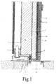
- the sheet 2 is extended at the edge of the door in a section 3, which is bent over the sheet metal by 90 ° and results in a folded portion. In this way, through the sheet 2 with the frontal section 3, a chamber 4, z. B. for receiving a durable material, formed, which may optionally be divided by another extending in the plane of the door panel 5, as far as necessary.
- Another sheet 6 which serves as a conclusion of the door construction and for receiving an alarm plate 8a, 8b, which is formed in two layers in the illustrated embodiment and will be described in more detail below.
- an insulating layer 10 or the like On the alarm plate 8a, 8b is optionally followed by an insulating layer 10 or the like, which is covered by a thin sheet metal plate 11, wherein the metal plate 11 has laterally bent portions 12 which close the door laterally, as is apparent from Fig. 1 evident.
- the filling of the chamber 4 consists of a demand-dependent material, preferably a burglary-resistant material.
- Fig. 1 the door frame is designated 14.
- the door construction described may be formed blunt or folded.
- a layer 8a according to Fig. 2 first, in one direction extending grooves 16 which are substantially parallel to each other and further grooves 17, 18, which in the illustrated embodiment extend transversely to the grooves 18, ie in a second direction, and further grooves 19, 20, 21, 22, 23, 24, 25, 26 which extend transversely to the grooves 16.
- the transverse grooves 17, 18 are provided in the illustrated embodiment at the upper edge and lower edge of the door and serve to deflect the conductor loops inserted into the grooves 16.
- the transverse grooves designated 19, 20 are located in front of and behind or above or below an outbreak 28, which may be provided for receiving door hinges, for example.
- transverse grooves 19, 20 it is achieved that the lying above and below the eruption 28 groups of grooves are interconnected, that is, in the region of the transverse grooves 19, 20 of the conductor loops forming electrically conductive wire does not over the Outbreak 28 away, but can be redirected before the outbreaks.
- a cable entrance 30 is provided and a cable exit 32, between which the conductor loop forming electrically conductive wire is laid substantially meandering running.
- a transverse groove 19, 20 is provided above the aperture 28 and below the aperture 28, which serves to allow deflection of the wire above and below the aperture 28, thereby ensuring that an electrically conductive wire between the cable inlet 30th and the cable exit 32 can be laid without interruption over the longitudinal and transverse grooves.
- a transverse groove 23 are provided above the aperture 34, 35 and a transverse groove 21 below this aperture 34, 35, which means that the electrically conductive wire is below the aperture 35 in the region of the transverse groove 21 meander-shaped from longitudinal groove to longitudinal groove is deflected and deflected in the groove 23 above the outbreak 34 accordingly. Further, it is provided in the illustrated embodiment that essentially no wire is laid above the transverse groove 26, but only below the groove 26, as a result of which the groove 26 serves in the same way for deflecting the wire.
- Fig. 6 shows a section to illustrate the deflection of the wire in the circular region I according to Fig. 2 , According to Fig. 6 are located in the groove 18 a plurality of wire loops 40, 41, 42 as arcuate connections against the extending in the longitudinal grooves sections of the electric wire, in Fig. 6 indicated by the reference numerals 44 to 50 are. As previously mentioned, a wire is endless between the cable entrance 30 and the cable exit 32 within the longitudinal grooves and the transverse grooves of Figs Fig. 2 laid plate 8a laid.
- Fig. 3 shows an example of a plate 8b with outbreaks, wherein the outbreak 28a and 28 of the plate 8a after Fig. 2 corresponding to the outbreaks 52 and 53 are opposite.
- an outbreak 54 is provided in the upper region of the plate 8b, which corresponds to a door portion of the plate 8b above the transverse groove 26.
- the plate 8b on an outbreak 56 which corresponds to the example of circular outbreaks 34, 35 of the plate 8a and covering in terms of area and has the shape of a rectangle or square.
- the plates 8a, 8b are firmly joined together by means of an adhesive, the adhesive preferably being applied to the surfaces or lands defined by the grooves of the plate 8a, provided that the adhesive does not enter the grooves and thus not electrically incorporates conductive wire. Rather, the electrically conductive wire is loosely laid in the longitudinal and transverse grooves of the plate 8a and is intended to remain loose within the longitudinal and transverse grooves even after the plate 8b has been applied to the plate 8a. In this way, it is ensured that when the door or the alarm plate is warped and / or in the case of expansion at higher temperatures, the electrically conductive wire is not damaged or travels.
- the wire forming the conductor loops in Fig. 2 generally designated 43, is preferably covered over its entire course within the grooves of the plate 8a lying through the plate 8b.
- the plate 8a has a plurality of vertically extending grooves, also referred to as longitudinal grooves, which, with 55 in Fig. 2 are indicated, and depending on demand, a corresponding number of transverse grooves such as the grooves 19, 20, 24, 25, etc.
- FIG. 4 and 5 show various examples of how the electrically conductive wire in the grooves 55 and 20, 21, etc. may be laid.
- Corresponding Fig. 4 is each of the grooves 55, which in the present case in the longitudinal direction, ie vertically extending, chosen with a width which makes up a multiple of the wire diameter of the wire 43, so that there is sufficient space in each groove 55 is to receive the wire 43.
- the groove height is preferably slightly larger than the diameter of the wire 43.
- the grooves are largely matched to the diameter of the wire 43, that is, the groove width as well as the groove height are only slightly larger than the diameter of the electric wire 43 is selected.
- the adhesive layer is in 4 and 5 60, and as mentioned above, is applied so as to exist only between the respective grooves 55 on a surface facing the plate 8b and not to flow into the grooves 55, 20, 21 and so on. In this way, it is ensured that the wire 43 runs loosely within the grooves 20, 21, etc. and 55.
- the adhesive layer should preferably be applied only on the webs between the adjacent grooves or at least partially on the webs between adjacent grooves, so that sticking to the electrical wire 43 is prevented.
- the alarm plate 8a, 8b is placed on the sheet metal wall 6 and glued or otherwise connected with this, such that the alarm plate 8a, 8b runs in the plane of the relevant door.
- the alarm plate 8a, 8b is preferably made of a fire protection material, as it is available on the market under the brand PROMATECT ® , that is, from a material which is non-combustible according to building material class DIN 4102 with a classification temperature of preferably 500 ° C.
- the conductor loop forming wire is preferably not bare, but provided with an insulating protective layer. In the case of a breakthrough, the wire is damaged or travels, and thus triggers an alarm via an electrical circuit not further explained.
- the alarm plate is composed of a plate 8a and a plate 8b.
- One of the plates has a longitudinally or vertically extending plurality of preferably mutually parallel grooves 55, 44, 45, 46, etc., and in the transverse direction to these grooves extending further grooves 17, 18, 19, 20, etc.
- a part of this transversely extending grooves 17, 18 provided along the lower edge of the plate 8a and for the most part receive the conductor loops between adjacent vertically extending grooves.
- Further transverse grooves are provided opposite to broken portions formed in the plate 8a, such as the portions 28, 28a, 30, 34, 35, which portions may have a rectangular or cylindrical shape.
- transversely extending grooves such as the grooves 19, 20, etc. to allow a corresponding guidance of the electric wire in front of or behind the outbreaks.
- the conductor loops in each case can be returned in time from a broken area and a passage of the wire can be excluded over the broken area, because in such a case, the wire would have to be loosely guided over the broken area and thus the risk would be exposed to damage.
Landscapes
- Physics & Mathematics (AREA)
- General Physics & Mathematics (AREA)
- Engineering & Computer Science (AREA)
- Civil Engineering (AREA)
- Structural Engineering (AREA)
- Burglar Alarm Systems (AREA)
- Elimination Of Static Electricity (AREA)
Abstract
Description
Aus der
Die
Der Erfindung liegt die Aufgabe zugrunde, eine Objektschutztür zu schaffen, die mit einer Alarmplatte versehen ist, die im Falle eines Einbruchs einen Alarm auslöst, aber derart konstruiert ist, dass durch Dehnung oder Verziehungen des Türblattes eine Beschädigung der alarmauslösenden Elemente verhindert wird.The invention has for its object to provide an object protection door, which is provided with an alarm plate, which triggers an alarm in the event of a burglary, but is constructed so that damage to the alarm-triggering elements is prevented by stretching or distortion of the door leaf.
Diese Aufgabe wird erfindungsgemäß gelöst durch eine Objektschutztür mit einem Türrahmen und einer Türverkleidung zur Aufnahme mindestens einer Schicht oder Platte mit widerstandsfähiger und/oder durchbruchsfester Eigenschaft, mit einer Alarmplatte, die aus wenigstens zwei Platten besteht, wobei die erste Platte in einer ersten Richtung verlaufende Nuten und in einer zweiten Richtung verlaufende Nuten aufweist, bei der die erste Platte Ausbrüche beinhaltet sowie zusätzliche, in der zweiten Richtung verlaufende Nuten aufweist, wobei die zusätzlichen Nuten in Abstand zu den Ausbrüchen vorgesehen sind, und bei der zumindest in einem Teil der Nuten ein Leiterschleifen ergebender elektrisch leitender Draht angeordnet ist.This object is achieved by an object protection door with a door frame and a door panel for receiving at least one layer or plate with resistant and / or breakdown-resistant property, with an alarm plate, which consists of at least two plates, wherein the first plate extending in a first direction grooves and grooves extending in a second direction, wherein the first plate includes cutouts and has additional grooves extending in the second direction, the additional grooves being spaced from the cutouts, and conductor loops in at least part of the grooves resulting electrically conductive wire is arranged.
Weitere Ausgestaltungen der Objektschutztür ergeben sich aus den Unteransprüchen.Further embodiments of the object door result from the dependent claims.
Die Erfindung schafft eine Objektschutztür mit einer Alarmplatte mit integrierten elektrisch leitenden Elementen, insbesondere in Form von Leiterschleifen bzw. Drahtschleifen, die eine ausreichende Steifigkeit aufweist und eine stabile Oberfläche besitzt. Derartige Objektschutztüren werden zum Beispiel im Bürobereich zur Absicherung von sensiblen EDV-Räumen eingesetzt. Die Tür weist einen Türrahmen auf, der den Einsatz mehrerer Türschichten gestattet, wobei die Alarmplatte vorzugsweise türaußenseitig aufgesetzt ist. Die Alarmplatte besteht aus vorzugsweise mindestens zwei Schichten, von welchen eine Schicht Nuten mit einer ersten Richtung und Nuten mit einer zweiten Richtung aufweist sowie ggf. Ausbrüche zur Aufnahme von Schlössern oder dergleichen, die vorgesetzte oder nachgesetzte Nuten aufweisen, um die elektrisch leitenden Elemente an den Ausbrüchen umzuleiten. Gemäß einer bevorzugten Ausführungsform verlaufen die Nuten in Vertikalrichtung und dienen als Führungsnuten zur Aufnahme eines elektrischen Drahtes. In Horizontalrichtung verlaufende Nuten sind insbesondere an der Türoberkante und Türunterkante vorgesehen sowie vor und hinter ausgebrochenen Bereichen zum Zwecke der Umleitung der Drahtelemente.The invention provides an object protection door with an alarm plate with integrated electrically conductive elements, in particular in the form of conductor loops or wire loops, which has sufficient rigidity and has a stable surface. Such object protection doors are used, for example, in the office area to protect sensitive computer rooms. The door has a door frame, which allows the use of multiple door layers, the alarm plate is preferably placed on the outside of the door. The alarm plate preferably consists of at least two layers, one layer of which has grooves with a first direction and grooves with a second direction and, if appropriate, cutouts for receiving locks or the like which have pre-set or recessed grooves in order to connect the electrically conductive elements to the Redirect outbreaks. According to a preferred embodiment, the grooves extend in the vertical direction and serve as guide grooves for receiving an electrical wire. Grooves extending in the horizontal direction are provided, in particular, on the upper edge of the door and lower edge of the door, and in front of and behind broken-out areas for the purpose of redirecting the wire elements.
Die mit Nuten versehene Schicht wird durch eine weitere Schicht abgedeckt, wobei zwischen den beiden Schichten ein Klebemittel eingesetzt wird, derart, dass die innerhalb der Nuten verlaufenden Leiterschleifen bzw. Drahtschleifen von dem Klebemittel freigehalten werden und damit lose innerhalb der Nuten zum Liegen kommen. Auf diese Weise ist sichergestellt, dass im Falle einer Dehnung durch Temperaturerhöhung oder geringfügiges Verziehen des Türblattes die die Leiterschleifen bzw. Drahtschleifen bildenden elektrischen Leiter nicht beschädigt werden.The grooved layer is covered by another layer, wherein an adhesive is used between the two layers, such that the conductor loops or wire loops running inside the grooves are kept free of the adhesive and thus lie loosely within the grooves. In this way, it is ensured that in the case of an elongation caused by temperature increase or slight distortion of the door leaf, the electrical conductors forming the conductor loops or wire loops are not damaged.
Im Folgenden wird eine bevorzugte Ausführungsform der erfindungsgemäßen Objektschutztür zur Erläuterung weiterer Vorteile und Merkmale anhand der Zeichnungen beschrieben.In the following, a preferred embodiment of the object protection door according to the invention for explaining further advantages and features will be described with reference to the drawings.
- Fig. 1Fig. 1
- eine horizontale Schnittansicht durch eine bevorzugte Ausführungsform einer Objektschutztür,a horizontal sectional view through a preferred embodiment of an object protection door,
- Fig. 2Fig. 2
- eine Draufsicht auf einen Teil der Alarmplatte mit den Nuten zur Aufnahme von Leiterschleifen,a plan view of a portion of the alarm plate with the grooves for receiving conductor loops,
- Fig. 3Fig. 3
-
eine Darstellung einer Ausführungsform einer zweiten Schicht der Alarmplatte, die auf die Platte nach
Fig. 2 aufgelegt wird,an illustration of an embodiment of a second layer of the alarm plate, which after the plateFig. 2 is hung up, - Fig. 4Fig. 4
- eine Teilschnittansicht durch die Alarmplatte, unda partial sectional view through the alarm plate, and
- Fig. 5Fig. 5
-
eine
Fig. 4 entsprechende Teilschnittansicht zur Darstellung einer weiteren Ausführungsform, undaFig. 4 corresponding partial sectional view to illustrate a further embodiment, and - Fig. 6Fig. 6
-
eine Teilansicht der ersten Schicht entsprechend der Darstellung in
Fig. 2 .a partial view of the first layer as shown in FIGFig. 2 ,
Nachfolgend wird die erfindungsgemäße Objektschutztür anhand der Zeichnungen näher beschrieben.
In
Die aus den Schichten 8a, 8b bestehende Alarmplatte wird nachfolgend unter Bezugnahme auf die
Gemäß
Soweit Ausbrüche in der Alarmplatte 8a, 8b vorhanden sind, sollen diese hinsichtlich der Platten 8a, 8b weitgehend deckungsgleich vorgesehen sein. Der die Leiterschleifen bildende Draht, in
Insgesamt weist die Platte 8a eine Vielzahl von in Vertikalrichtung verlaufenden Nuten, auch als Längsnuten bezeichnet, auf, die mit 55 in
Wie sich aus
Der die Leiterschleifen bildende Draht ist vorzugsweise nicht blank, sondern mit einer isolierenden Schutzschicht versehen. Im Falle eines Durchbruches wird der Draht beschädigt oder reist, und löst auf diese Weise einen Alarm über eine nicht weiter erläuterte elektrische Schaltung aus.The conductor loop forming wire is preferably not bare, but provided with an insulating protective layer. In the case of a breakthrough, the wire is damaged or travels, and thus triggers an alarm via an electrical circuit not further explained.
Bei den vorstehend beschriebenen Ausführungsformen besteht die Alarmplatte aus einer Platte 8a und einer Platte 8b. Eine der Platten weist eine in Längsrichtung bzw. Vertikalrichtung verlaufende Mehrzahl von vorzugsweise parallel zueinander stehenden Nuten 55, 44, 45, 46 usw. auf, sowie in Querrichtung zu diesen Nuten verlaufende weitere Nuten 17, 18, 19, 20 usw. Ein Teil dieser in Querrichtung verlaufenden Nuten 17, 18 die entlang der Unterkante bzw. Oberkante der Platte 8a vorgesehen sind und zum überwiegenden Teile die Leiterschleifen bzw. Leiterbögen zwischen benachbarten, in Vertikalrichtung verlaufenden Nuten, aufnehmen. Weitere quer verlaufende Nuten sind gegenüber in der Platte 8a ausgebildeten ausgebrochenen Bereichen wie den Bereichen 28, 28a, 30, 34, 35 vorgesehen, wobei diese ausgebrochenen Bereiche eine rechteckige oder zylindrische Form haben können. In Abstand zu diesen ausgebrochenen Bereichen sind entsprechende in Querrichtung verlaufende Nuten vorgesehen, wie die Nuten 19, 20 usw. um eine entsprechende Führung des elektrischen Drahtes vor oder hinter den Ausbrüchen zu ermöglichen. Auf diese Weise wird erreicht, dass die Leiterschleifen jeweils rechtzeitig von einem ausgebrochenen Bereich zurückgeführt werden können und ein Durchführen des Drahtes über den ausgebrochenen Bereich ausgeschlossen werden kann, weil in einem solchen Falle der Draht lose über dem ausgebrochenen Bereich geführt werden müsste und damit der Gefahr ausgesetzt sein würde, beschädigt zu werden. Aufgrund der quer verlaufenden Nuten zur Umleitung des Drahtes vor oder hinter Ausbrüchen, d.h. oberhalb oder unterhalb von Ausbrüchen, ergibt es sich, dass die einzelnen vertikalen Längenabschnitte des die Leiterschleifen bildenden Drahtes unterschiedlich groß sind und nicht jeweils über eine Länge sich erstrecken, die zwischen den Nuten 17 und 18 definiert ist.In the embodiments described above, the alarm plate is composed of a
Claims (5)
mit einer Alarmplatte (8a, 8b), die aus wenigstens zwei Platten (8a, 8b) besteht,
wobei die erste Platte (8a) in einer ersten Richtung verlaufende Nuten (55) und in einer zweiten Richtung verlaufende Nuten (17, 18) aufweist,
bei der die erste Platte (8a) Ausbrüche (28, 28a, 34, 35) beinhaltet sowie zusätzliche, in der zweiten Richtung verlaufende Nuten (19, 20, 21, 22, 23 usw.) aufweist, wobei die zusätzlichen Nuten in Abstand zu den Ausbrüchen (28, 28a, 34, 35) vorgesehen sind, und bei der zumindest in einem Teil der Nuten ein Leiterschleifen ergebender elektrisch leitender Draht (43) angeordnet ist.Object protection door with a door frame (1) and a door trim (3, 6, 11, 12) for receiving at least one layer or panel (4) with a resistant and / or breakdown-resistant property,
with an alarm plate (8a, 8b) consisting of at least two plates (8a, 8b),
the first plate (8a) having grooves (55) extending in a first direction and grooves (17, 18) extending in a second direction,
wherein the first plate (8a) includes cutouts (28, 28a, 34, 35) and additional grooves (19, 20, 21, 22, 23, etc.) extending in the second direction, the additional grooves being spaced apart the outbreaks (28, 28a, 34, 35) are provided, and in which at least in a part of the grooves a conductor loops resulting electrically conductive wire (43) is arranged.
dadurch gekennzeichnet, dass
die zusätzlichen Nuten (19, 20, 21, 22, 23) oberhalb bzw. unterhalb eines Ausbruchs (28, 28a, 34, 35) vorgesehen sind zur Aufnahme von Abschnitten des elektrisch leitfähigen Drahtes.Object protection door according to claim 1,
characterized in that
the additional grooves (19, 20, 21, 22, 23) above or below an opening (28, 28 a, 34, 35) are provided for receiving portions of the electrically conductive wire.
dadurch gekennzeichnet, dass
in der zweiten Richtung verlaufende Nuten (17, 18) im Bereich der Türoberkante und im Bereich der Türunterkante vorgesehen sind.Object protection door according to at least one of the preceding claims,
characterized in that
in the second direction extending grooves (17, 18) are provided in the region of the door upper edge and in the region of the lower door edge.
dadurch gekennzeichnet, dass
zwischen den Platten der Alarmplatte (8a, 8b) ein Klebemittel vorgesehen ist.Object protection door according to at least one of the preceding claims,
characterized in that
between the plates of the alarm plate (8a, 8b) an adhesive is provided.
dadurch gekennzeichnet, dass
das Klebemittel (60) auf Flächenabschnitten der die Nuten (55, 19, 20, 22, 23) aufweisenden Platte (8a) aufgebracht ist, die der zweiten Platte (8b) gegenüberliegen.Object protection door according to claim 4,
characterized in that
the adhesive (60) is applied to surface portions of the grooves (55, 19, 20, 22, 23) having plate (8a) facing the second plate (8b).
Applications Claiming Priority (1)
| Application Number | Priority Date | Filing Date | Title |
|---|---|---|---|
| DE200810040303 DE102008040303B3 (en) | 2008-07-10 | 2008-07-10 | Object protective door |
Publications (3)
| Publication Number | Publication Date |
|---|---|
| EP2143865A2 true EP2143865A2 (en) | 2010-01-13 |
| EP2143865A3 EP2143865A3 (en) | 2011-12-07 |
| EP2143865B1 EP2143865B1 (en) | 2014-01-15 |
Family
ID=40936604
Family Applications (1)
| Application Number | Title | Priority Date | Filing Date |
|---|---|---|---|
| EP20080169232 Active EP2143865B1 (en) | 2008-07-10 | 2008-11-17 | Object protective door |
Country Status (2)
| Country | Link |
|---|---|
| EP (1) | EP2143865B1 (en) |
| DE (1) | DE102008040303B3 (en) |
Families Citing this family (2)
| Publication number | Priority date | Publication date | Assignee | Title |
|---|---|---|---|---|
| SI2633145T1 (en) | 2010-10-27 | 2014-11-28 | Baumert (Societe Par Actions Simplifiee Unipersonelle | Hermetische feuerschutztur |
| DE102011119189A1 (en) | 2011-11-23 | 2013-05-23 | Karl-Heinz Schmezer | Safety device for lockable room used in home, has wire safety alarm signal that is triggered, while interrupting outside partial alarm wires lying in region of wall and/or door element |
Citations (3)
| Publication number | Priority date | Publication date | Assignee | Title |
|---|---|---|---|---|
| GB228730A (en) | 1924-03-07 | 1925-02-12 | George Bertram Carpenter | Improvements relating to burglar alarms |
| DE4437293A1 (en) | 1994-10-19 | 1996-04-25 | Weisschaedel Geb Weckesser Hed | Security door e.g. for public buildings |
| JP2003248870A (en) | 2002-02-22 | 2003-09-05 | Shuzo Hazue | Metal-framed glass sliding door with crime-preventing function |
Family Cites Families (4)
| Publication number | Priority date | Publication date | Assignee | Title |
|---|---|---|---|---|
| GB202816A (en) * | 1922-07-24 | 1923-08-30 | George William Frost | An improvement in safes, strong room doors and the like |
| US4234875A (en) * | 1978-03-06 | 1980-11-18 | Sandstone, Inc. | Security structure |
| EP0396869A1 (en) * | 1989-05-09 | 1990-11-14 | Thomas Matouschek | Alarm device for surface protection |
| DE9300924U1 (en) * | 1993-01-23 | 1993-03-18 | ON Spectral GmbH Optronic und Nachrichtentechnik, 2732 Sittensen | Metal grid secured with optical fibers |
-
2008
- 2008-07-10 DE DE200810040303 patent/DE102008040303B3/en active Active
- 2008-11-17 EP EP20080169232 patent/EP2143865B1/en active Active
Patent Citations (3)
| Publication number | Priority date | Publication date | Assignee | Title |
|---|---|---|---|---|
| GB228730A (en) | 1924-03-07 | 1925-02-12 | George Bertram Carpenter | Improvements relating to burglar alarms |
| DE4437293A1 (en) | 1994-10-19 | 1996-04-25 | Weisschaedel Geb Weckesser Hed | Security door e.g. for public buildings |
| JP2003248870A (en) | 2002-02-22 | 2003-09-05 | Shuzo Hazue | Metal-framed glass sliding door with crime-preventing function |
Also Published As
| Publication number | Publication date |
|---|---|
| DE102008040303B3 (en) | 2009-09-10 |
| EP2143865B1 (en) | 2014-01-15 |
| EP2143865A3 (en) | 2011-12-07 |
Similar Documents
| Publication | Publication Date | Title |
|---|---|---|
| EP1416636B2 (en) | Sensor element for a capacitive touch switch with an electrically conductive element and method of producing the same | |
| EP2106006A2 (en) | Cable feedthrough | |
| EP3117112A1 (en) | Fastening system for assembling appliances, in particular electrical appliances | |
| WO2019242925A1 (en) | Support system for arranging a photovoltaic unit having at least one photovoltaic module | |
| DE202009014251U1 (en) | System for connecting electrical conductors with mutually different potentials as well as plug-in adapters for the system | |
| EP2143865B1 (en) | Object protective door | |
| EP1538297B1 (en) | Partitioned insert for fire doors | |
| DE102017125231A1 (en) | Conduit holder system, connection part, busbar element, busbar system, mechanical connection element, method for producing a conductor rail element and method for producing a conductor rail system | |
| DE102009008037B4 (en) | Modular safety cabinet for holding data and / or computer equipment | |
| DE19948329C2 (en) | Control cabinet and process for its manufacture | |
| EP2660403B1 (en) | Insulation holder | |
| DE10110795A1 (en) | Surround profile firestop endfaces have edges joined by web pieces between slots either side in rows parallel to the profile using firestop strips held in center part groove. | |
| EP3566271B1 (en) | Door for an electrical cabinet | |
| EP3454441B1 (en) | Electrical junction box | |
| DE2144640A1 (en) | Connection of electrical wires or cable cores to electrical busbars | |
| EP0886992B1 (en) | Equipment chassis for electronic equipment | |
| DE202011100030U1 (en) | Device for connecting and fixing lattice mats | |
| DE102008056483B4 (en) | Busbar arrangement with contacting area | |
| DE102016214042B4 (en) | Fuse unit | |
| EP2056405B1 (en) | Connector element for mechanically fixing pipes or the like to a casing or the like and for providing a terminal for the connection to a protective earth conductor | |
| EP3557655A1 (en) | Battery pack and electric hand-held tool | |
| WO2012025177A1 (en) | Wire strain relief for connection or distribution modules and connection or distribution module | |
| EP3716423B1 (en) | Tool for the aligned mounting of tool inserts | |
| DE202023101998U1 (en) | Heat-absorbing fence element and privacy fence | |
| DE20105501U1 (en) | Busbar |
Legal Events
| Date | Code | Title | Description |
|---|---|---|---|
| PUAI | Public reference made under article 153(3) epc to a published international application that has entered the european phase |
Free format text: ORIGINAL CODE: 0009012 |
|
| 17P | Request for examination filed |
Effective date: 20081117 |
|
| AK | Designated contracting states |
Kind code of ref document: A2 Designated state(s): AT BE BG CH CY CZ DE DK EE ES FI FR GB GR HR HU IE IS IT LI LT LU LV MC MT NL NO PL PT RO SE SI SK TR |
|
| AX | Request for extension of the european patent |
Extension state: AL BA MK RS |
|
| PUAL | Search report despatched |
Free format text: ORIGINAL CODE: 0009013 |
|
| AK | Designated contracting states |
Kind code of ref document: A3 Designated state(s): AT BE BG CH CY CZ DE DK EE ES FI FR GB GR HR HU IE IS IT LI LT LU LV MC MT NL NO PL PT RO SE SI SK TR |
|
| AX | Request for extension of the european patent |
Extension state: AL BA MK RS |
|
| RIC1 | Information provided on ipc code assigned before grant |
Ipc: E06B 3/82 20060101ALI20111028BHEP Ipc: G08B 13/04 20060101ALI20111028BHEP Ipc: G08B 13/12 20060101ALI20111028BHEP Ipc: E05G 1/10 20060101ALI20111028BHEP Ipc: E05G 1/024 20060101AFI20111028BHEP |
|
| 17Q | First examination report despatched |
Effective date: 20120502 |
|
| AKX | Designation fees paid |
Designated state(s): CH DE FR GB LI |
|
| RBV | Designated contracting states (corrected) |
Designated state(s): CH FR GB LI |
|
| REG | Reference to a national code |
Ref country code: DE Ref legal event code: R108 |
|
| RBV | Designated contracting states (corrected) |
Designated state(s): CH FI FR GB LI |
|
| REG | Reference to a national code |
Ref country code: DE Ref legal event code: R108 Effective date: 20120919 |
|
| GRAP | Despatch of communication of intention to grant a patent |
Free format text: ORIGINAL CODE: EPIDOSNIGR1 |
|
| GRAS | Grant fee paid |
Free format text: ORIGINAL CODE: EPIDOSNIGR3 |
|
| GRAA | (expected) grant |
Free format text: ORIGINAL CODE: 0009210 |
|
| AK | Designated contracting states |
Kind code of ref document: B1 Designated state(s): CH FI FR GB LI |
|
| REG | Reference to a national code |
Ref country code: GB Ref legal event code: FG4D Free format text: NOT ENGLISH Ref country code: CH Ref legal event code: EP |
|
| REG | Reference to a national code |
Ref country code: CH Ref legal event code: NV Representative=s name: HEPP WENGER RYFFEL AG, CH |
|
| PLBE | No opposition filed within time limit |
Free format text: ORIGINAL CODE: 0009261 |
|
| STAA | Information on the status of an ep patent application or granted ep patent |
Free format text: STATUS: NO OPPOSITION FILED WITHIN TIME LIMIT |
|
| 26N | No opposition filed |
Effective date: 20141016 |
|
| REG | Reference to a national code |
Ref country code: FR Ref legal event code: PLFP Year of fee payment: 8 |
|
| REG | Reference to a national code |
Ref country code: FR Ref legal event code: PLFP Year of fee payment: 9 |
|
| REG | Reference to a national code |
Ref country code: FR Ref legal event code: PLFP Year of fee payment: 10 |
|
| P01 | Opt-out of the competence of the unified patent court (upc) registered |
Effective date: 20230419 |
|
| PGFP | Annual fee paid to national office [announced via postgrant information from national office to epo] |
Ref country code: GB Payment date: 20231123 Year of fee payment: 16 |
|
| PGFP | Annual fee paid to national office [announced via postgrant information from national office to epo] |
Ref country code: FR Payment date: 20231120 Year of fee payment: 16 Ref country code: FI Payment date: 20231121 Year of fee payment: 16 Ref country code: CH Payment date: 20231201 Year of fee payment: 16 |