EP2143676A1 - Paper sheet taking-out device - Google Patents
Paper sheet taking-out device Download PDFInfo
- Publication number
- EP2143676A1 EP2143676A1 EP08710526A EP08710526A EP2143676A1 EP 2143676 A1 EP2143676 A1 EP 2143676A1 EP 08710526 A EP08710526 A EP 08710526A EP 08710526 A EP08710526 A EP 08710526A EP 2143676 A1 EP2143676 A1 EP 2143676A1
- Authority
- EP
- European Patent Office
- Prior art keywords
- take
- sheet
- postal matter
- out position
- holes
- Prior art date
- Legal status (The legal status is an assumption and is not a legal conclusion. Google has not performed a legal analysis and makes no representation as to the accuracy of the status listed.)
- Withdrawn
Links
Images










Classifications
-
- B—PERFORMING OPERATIONS; TRANSPORTING
- B65—CONVEYING; PACKING; STORING; HANDLING THIN OR FILAMENTARY MATERIAL
- B65H—HANDLING THIN OR FILAMENTARY MATERIAL, e.g. SHEETS, WEBS, CABLES
- B65H1/00—Supports or magazines for piles from which articles are to be separated
- B65H1/02—Supports or magazines for piles from which articles are to be separated adapted to support articles on edge
-
- B—PERFORMING OPERATIONS; TRANSPORTING
- B65—CONVEYING; PACKING; STORING; HANDLING THIN OR FILAMENTARY MATERIAL
- B65H—HANDLING THIN OR FILAMENTARY MATERIAL, e.g. SHEETS, WEBS, CABLES
- B65H3/00—Separating articles from piles
- B65H3/08—Separating articles from piles using pneumatic force
- B65H3/12—Suction bands, belts, or tables moving relatively to the pile
- B65H3/124—Suction bands or belts
-
- B—PERFORMING OPERATIONS; TRANSPORTING
- B65—CONVEYING; PACKING; STORING; HANDLING THIN OR FILAMENTARY MATERIAL
- B65H—HANDLING THIN OR FILAMENTARY MATERIAL, e.g. SHEETS, WEBS, CABLES
- B65H1/00—Supports or magazines for piles from which articles are to be separated
- B65H1/02—Supports or magazines for piles from which articles are to be separated adapted to support articles on edge
- B65H1/025—Supports or magazines for piles from which articles are to be separated adapted to support articles on edge with controlled positively-acting mechanical devices for advancing the pile to present the articles to the separating device
-
- B—PERFORMING OPERATIONS; TRANSPORTING
- B65—CONVEYING; PACKING; STORING; HANDLING THIN OR FILAMENTARY MATERIAL
- B65H—HANDLING THIN OR FILAMENTARY MATERIAL, e.g. SHEETS, WEBS, CABLES
- B65H3/00—Separating articles from piles
- B65H3/08—Separating articles from piles using pneumatic force
- B65H3/10—Suction rollers
-
- B—PERFORMING OPERATIONS; TRANSPORTING
- B65—CONVEYING; PACKING; STORING; HANDLING THIN OR FILAMENTARY MATERIAL
- B65H—HANDLING THIN OR FILAMENTARY MATERIAL, e.g. SHEETS, WEBS, CABLES
- B65H3/00—Separating articles from piles
- B65H3/08—Separating articles from piles using pneumatic force
- B65H3/12—Suction bands, belts, or tables moving relatively to the pile
-
- B—PERFORMING OPERATIONS; TRANSPORTING
- B65—CONVEYING; PACKING; STORING; HANDLING THIN OR FILAMENTARY MATERIAL
- B65H—HANDLING THIN OR FILAMENTARY MATERIAL, e.g. SHEETS, WEBS, CABLES
- B65H7/00—Controlling article feeding, separating, pile-advancing, or associated apparatus, to take account of incorrect feeding, absence of articles, or presence of faulty articles
- B65H7/16—Controlling air-supply to pneumatic separators
-
- B—PERFORMING OPERATIONS; TRANSPORTING
- B65—CONVEYING; PACKING; STORING; HANDLING THIN OR FILAMENTARY MATERIAL
- B65H—HANDLING THIN OR FILAMENTARY MATERIAL, e.g. SHEETS, WEBS, CABLES
- B65H2511/00—Dimensions; Position; Numbers; Identification; Occurrences
- B65H2511/20—Location in space
- B65H2511/21—Angle
- B65H2511/214—Inclination
-
- B—PERFORMING OPERATIONS; TRANSPORTING
- B65—CONVEYING; PACKING; STORING; HANDLING THIN OR FILAMENTARY MATERIAL
- B65H—HANDLING THIN OR FILAMENTARY MATERIAL, e.g. SHEETS, WEBS, CABLES
- B65H2511/00—Dimensions; Position; Numbers; Identification; Occurrences
- B65H2511/50—Occurence
- B65H2511/51—Presence
-
- B—PERFORMING OPERATIONS; TRANSPORTING
- B65—CONVEYING; PACKING; STORING; HANDLING THIN OR FILAMENTARY MATERIAL
- B65H—HANDLING THIN OR FILAMENTARY MATERIAL, e.g. SHEETS, WEBS, CABLES
- B65H2511/00—Dimensions; Position; Numbers; Identification; Occurrences
- B65H2511/50—Occurence
- B65H2511/515—Absence
-
- B—PERFORMING OPERATIONS; TRANSPORTING
- B65—CONVEYING; PACKING; STORING; HANDLING THIN OR FILAMENTARY MATERIAL
- B65H—HANDLING THIN OR FILAMENTARY MATERIAL, e.g. SHEETS, WEBS, CABLES
- B65H2515/00—Physical entities not provided for in groups B65H2511/00 or B65H2513/00
- B65H2515/20—Volume; Volume flow
-
- B—PERFORMING OPERATIONS; TRANSPORTING
- B65—CONVEYING; PACKING; STORING; HANDLING THIN OR FILAMENTARY MATERIAL
- B65H—HANDLING THIN OR FILAMENTARY MATERIAL, e.g. SHEETS, WEBS, CABLES
- B65H2701/00—Handled material; Storage means
- B65H2701/10—Handled articles or webs
- B65H2701/19—Specific article or web
- B65H2701/1916—Envelopes and articles of mail
Definitions
- the present invention relates to a sheet take-out apparatus for taking out sheets in the stacking state one by one in the surface direction.
- a sheet processing apparatus for moving the plurality of sheets in a stacking direction, conveying a sheet at one end to a take-out position, generating a negative pressure via holes of a belt standing by at the take-out position, absorbing the sheet, moving the belt in this state in a take-out direction, thereby taking out the absorbed sheet in a surface direction is known (for example, refer to Patent Document 1).
- the apparatus particularly detects the density of sheets conveyed to the take-out position and controls the conveying speed of the sheets conveyed to the take-out position according to the density of sheets. By doing this, the sheet take-out operation is stabilized and the processing efficiency is enhanced.
- Patent Document 1 Japanese Patent Application 2001-335165
- An object of the present invention is to provide a sheet take-out apparatus for stabilizing the sheet take-out operation and enhancing the processing efficiency.
- the sheet take-out apparatus of the present invention includes an insertion portion to stack and insert a plurality of sheets in an upright state, a supply structure to move the plurality of inserted sheets in the stacking direction and supply a sheet at a leading edge in a moving direction to a take-out position at one end of the insertion portion, a take-out structure to rotate in contact with the sheet supplied to the take-out position, thereby take out the sheet in a direction almost perpendicular to the stacking direction, and a suction structure to permit an air current to act on the sheet at the leading edge in the moving direction which is supplied to the take-out position by the supply structure and absorbing the sheet toward the take-out position, wherein the suction structure, so as to raise the fallen sheet at the leading edge in the moving direction and permit it to face the take-out structure, makes the flow rate of the air current acting on the sheet different in the surface of the sheet.
- the sheet supplied to the take-out position in the fallen state by permitting an air current to act on it by the suction structure, faces the take-out structure, so that it is possible to permit the sheet to make contact with the take-out structure surely and stably, stabilize the sheet take-out operation, and enhance the processing efficiency.
- the sheet take-out apparatus of the present invention includes an insertion portion to stack and insert a plurality of sheets in an upright state, a supply structure to move the plurality of inserted sheets in the stacking direction and supply the sheet at the leading edge in the moving direction to the take-out position at one end of the insertion portion, a take-out structure to rotate in contact with the sheet supplied to the take-out position, thereby take out the sheet in a direction almost perpendicular to the stacking direction, a suction structure to permit an air current to act on the sheet, supplied to the take-out position by the supply structure, at the leading edge in the moving direction and absorb the sheet toward the take-out position, and a posture detection portion to detect the posture of the sheet, supplied to the take-out position by the supply structure, at the leading edge in the moving direction, wherein the suction structure, according to the detection results by the posture detection portion, switches a position to permit the air current to act on the sheet at the leading edge in the moving direction.
- the position for permitting the air current to act on the sheet by the absorbing structure is switched, so that even when the sheet is supplied to the take-out position in any posture, it can face surely the take-out structure.
- the sheet take-out apparatus of the present invention includes an insertion portion to stack and insert a plurality of sheets in an upright state, a supply structure to move the plurality of inserted sheets in the stacking direction and supply a sheet at a leading edge in a moving direction to the take-out position at one end of the insertion portion, a take-out structure to rotate in contact with the sheet supplied to the take-out position, thereby take out the sheet in the almost horizontal direction almost perpendicular to the stacking direction, and a suction structure to permit an air current to act on the sheet, supplied to the take-out position by the supply structure, at the leading edge in the moving direction and absorb the sheet toward the take-out position, wherein the supply structure supplies the sheet at the leading edge in the moving direction toward the take-out position in a posture that the upper end thereof is inclined toward an upstream side in the moving direction, and the suction structure, via holes arranged above the position where the take-out structure makes contact with the sheet supplied to the take-out position, permits an air current to act on the neighborhood
- the suction structure via the holes arranged above the position where the take-out structure makes contact with the sheet at the leading edge in the moving direction which is supplied to the take-out position, the suction structure permits the air current for sucking the sheet to act on the sheet, so that the take-out structure and the concerned sheet can make contact with each other at the position where the suction structure sucks the sheet to the take-out position, and the sheet at the leading edge in the moving direction can face surely the take-out structure
- FIG. 1 shows a block diagram of the schematic structure of a postal matter processing apparatus 100 (hereinafter, referred to as just a processing apparatus 100) including a sheet take-out apparatus 1 (hereinafter, referred to as just a take-out apparatus 1) relating to the embodiments of the present invention.
- the processing apparatus 100 in addition to the take-out apparatus 1, includes a discriminator 102, a rejection portion 104, a switch-back portion 106, and a stacker 108.
- sheets processed by the processing apparatus 100 of this embodiment are postal matter, though processed media (that is, sheets) are not limited to postal matter.
- Postal matter is set in the take-out apparatus 1 in the stacking state and since the take-out apparatus 1 is operated as described later, is taken out one by one onto a conveying path 101.
- a conveying path 101 On the conveying path 101, a plurality of sets of endless conveying belts not drawn are extended so as to hold the conveying path 101 and the postal matter is held and conveyed between the conveying belts.
- the postal matter taken out on the conveying path 101 passes through the discriminator 102 and here, various information is read from the postal matter.
- the discriminator 102 on the basis of the read various information, discriminates the conveying posture and sorting destination of the postal matter. Particularly, the discriminator 102 reads the destination information such as the zip code and address which are written on each postal matter and discriminates the sorting destination.
- the postal matter passing through the discriminator 102 is distributed in the conveying direction thereof via a gate G1. Namely, the postal matter which is discriminated as postal matter to be rejected by the discriminator 102 is conveyed to the rejection portion 104 via the gate G1 and the other postal matter is conveyed to the stacker 108 via the gate G1.
- the discriminator 102 discriminates that the concerned postal matter must be reversed in the conveying direction
- the postal matter is fed to the switch-back portion 106 via a gate G2 and the conveying direction is reversed here.
- the postal matter which does not need to be reversed in the conveying direction makes a detour to the switch-back portion 106 via the gate G2 and is conveyed to the stacker 108.
- the postal matter fed to the stacker 108 on the conveying path 101 is sorted and stacked in a sorting and stacking pocket not drawn according to the discrimination results by the discriminator 102.
- the postal matter sorted and stacked in each sorting and stacking pocket is stacked in the state that the top and bottom thereof are arranged properly.
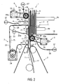
- FIG. 2 shows a plan view showing the take-out apparatus 1 relating the embodiments of the present invention which is viewed from above.
- the take-out apparatus 1 includes an insertion portion 2 for inserting a plurality of sheets P in the stacking state, a supply structure (described later) for moving the plurality of inserted sheets P in the stacking direction and supplying the sheet at the leading edge in the moving direction to a take-out position 20, a take-out structure 3 for feeding the postal matter P supplied to the take-out position 20 in the surface direction thereof and taking out it on a conveying path 10 which will be described later, a suction structure 4 for taking out, among the postal matter inserted via the insertion portion 2, the postal matter P at the leading edge and sucking it toward the take-out position 20, a separation structure 5 for separating the second and subsequent postal matter P which are taken out following the postal matter P taken out from the take-out position 20, an aiding structure 6 for permitting a negative pressure to act on the postal matter P supplied to the take-out position 20 on the upstream side
- the take-out apparatus 1 includes a sensor 11 for detecting passing of the postal matter P taken out from the take-out position 20 at one end of the insertion portion 2 onto the conveying path 10 and a plurality of conveying guides 12 to 18.
- the sensor 11 includes a light emission portion and a light receiving portion so as to hold the conveying path 10 through which the postal matter P passes and when the optical axis thereof is blocked off by the postal matter P, detects passing of the concerned postal matter P.
- the sensors 11 are arranged in a plurality of rows in the perpendicular direction to the sheet of paper on which FIG. 2 is drawn or a line sensor composed of elements lined up in the perpendicular direction to the sheet of paper are arranged.
- the plurality of conveying guides 12 to 18 guide the movement and conveyance thereof by making contact with the end side and surface of the postal matter P.
- a plurality of postal mater P are inserted together in the stacking state and in the upright state.
- two floor belts 8a and 8b for permitting the lower end of each of the postal matter P to make contact with them and moving it in the stacking direction (the direction of an arrow F shown in FIG. 2 ) are arranged.
- a backup plate 9 simply connected to the floor belt 8b (one of the two) for moving in the direction of the arrow F in cooperation with it, thereby supplying the postal matter P at the leading edge in the moving direction to the take-out position 20 is arranged.
- the two floor belts 8a and 8b and the backup plate 9 function as a supply structure of the present invention.
- the conveying guide 18 is extended to the position for specifying one side of the insertion portion 2 in the direction of the arrow F and guides the end side of each of the postal matter P.
- the conveying guides 12, 13, and 14 are arranged in line with each other along the take-out position 20 on one end side of the insertion portion 2, function so as to stop the postal matter P at the leading edge in the moving direction which is supplied in the direction of the arrow F at the take-out position 20, and function so as to guide the postal matter P taken out from the take-out position 20 in contact with one side thereof.
- the take-out structure 3 includes a chamber 21, the guide 14, and a vacuum pump 22 (or an equivalent article). Further, the take-out structure 3 includes an endless take-out belt 23 that at least the part of a fixed area moves in the direction of an arrow T1 (the take-out direction of the postal matter P) shown in the drawing along the take-out position 20 and a motor 24 for driving the take-out belt 23.
- the take-out belt 23, so that at least one part thereof moves in the direction of the arrow T1 shown in the drawing along the take-out position 20 and the conveying path 10 continued from the take-out position 20, is wound with a plurality of rollers 25, stretched, and positioned.
- the guide 14 is arranged at the position opposite to the take-out position 20 so as to hold the belt inside the take-out belt 23.
- the chamber 21 is arranged on the back side of the guide 14, that is, at the position opposite to the take-out position 20 by holding the take-out belt 23 and the guide 14.
- the take-out belt 23, as shown in FIG. 3 by partially enlarged, has many absorbing holes 23a.
- the guide 14, as shown in FIG. 4 in the moving direction T1 of the take-out belt 23 (that is, the take-out direction of the postal matter P), has a plurality of long and narrow slits 14a.
- a negative pressure acts on the postal matter P supplied to the take-out position 20 and the postal matter P is absorbed to the surface of the take-out belt 23 and in correspondence with movement of the take-out belt 23, is taken out from the take-out position 20 onto the conveying path 10.
- the absorbing force by the vacuum pump 22 in the direction of the arrow S1 is set so that the conveying force for discharging the first postal matter P absorbed to the take-out belt 23 in the take-out direction T1 is at least larger than the frictional force acting between the first sheet and the second sheet.
- the take-out structure 3 basically, separates the postal matter P at the take-out position 20 one by one and discharges them onto the conveying path 10, though sheets which are discharged onto the conveying path 10 in the stacking state of a plurality of sheets are separated one by one by the separation structure 5 which will be described later.
- the suction structure 4 includes a chamber 26 arranged on the back side of the conveying guide 13 for the take-out position 20 and a blower 27 (or an equivalent article) for sucking air in the chamber 26.
- the chamber 26, between the take-out structure 3 aforementioned and the aiding structure 6 which will be described later, is arranged in the neighborhood of the take-out position 20 in the posture that the opening thereof not drawn is opposite to the back of the guide 13.
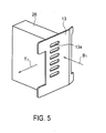
- the guide 13, as shown in Fig. 5 as partially enlarged has a plurality of holes 13a in accordance with the width of the opening of the chamber 26. In other words, the plurality of holes 13a are arranged in the opening of the chamber 26.
- the suction structure 4 by installation of the suction structure 4, the postal matter P to be taken out next can be supplied quickly to the take-out position 20 and even if the supply force by the supply structures 8a, 8b, and 9 in the direction of the arrow F is weak, only the first postal matter P can be always supplied stably and quickly to the take-out position 20. By doing this, the aforementioned take-out operation of the postal matter P by the take-out structure 3 can be quickened.
- the separation structure 5, for the conveying path 10 extended on the downstream side (downward in FIG.2 ) of the take-out position 20, is installed on the opposite side of the take-out structure 3.
- the separation structure 5, by permitting a negative pressure to act on the postal matter P conveyed on the conveying path 10 from the opposite side of the take-out structure 3, gives separation torque in the opposite direction to the take-out direction of the postal matter P to it.
- the separation structure 5 is operated, even when, following the postal matter P taken out from the take-out position 20, the second and subsequent postal matter P (three or more pieces of postal matter may be taken out in the stacking state) are taken out, the second and subsequent postal matter P are stopped by the negative pressure and separation torque or are returned in the opposite direction and are separated from the first postal matter P.
- the separation structure 5, as shown in FIG. 6 as partially enlarged, has a separation roller 31 installed rotatably in both forward and backward directions in the take-out direction T1 of the postal matter P.
- the separation roller 31, as shown also in FIG. 7 is rotatably attached to the rotary shaft fixedly attached to the conveying path 10, that is, a cylinder 32 having a chamber 33, which will be described later, via a bearing 34 and has many absorbing holes 31a passing through so as to connect the inner peripheral surface and outer peripheral surface.
- the separation roller 31 is formed by a rigid body of an almost cylindrical metallic material and is arranged at the position where the outer peripheral surface thereof is exposed onto the conveying path 10.
- FIG. 7 shows a cross section view along the broken line VII-VII shown in FIH. 6.
- the separation structure 5 includes an AC servomotor 35 for rotating the separation roller 31 at desired torque in both forward and backward directions and an endless timing belt 36 for transferring the drive force by the motor 35 to the separation roller 31.
- the timing belt 36 is wound and stretched round a pulley 35a fixed to the rotary shaft of the motor 35 and a pulley (not drawn) fixed to a rotary shaft 31b (refer to FIG. 7 ) of the separation roller 31.
- the separation structure 5 has a vacuum pump 37 (or an equivalent article) connected to the chamber 33 of the cylinder 32 to which the separation roller 31 is attached rotatably via a pipe 38.
- a negative pressure acts on the surface of the postal matter P passing on the conveying path 10 and the postal matter P is absorbed to the outer peripheral surface of the separation roller 31.
- the separation roller 31 is rotating, also to the postal matter P absorbed to the outer peripheral surface of the separation roller 31, the conveying force in the rotational direction of the separation roller 31 is given.
- the area where the negative pressure acts on the postal matter P via the absorbing hole 310 of the separation roller 31 is referred to as a separation area As.
- the AC servomotor 35 basically, drives and controls the separation roller 31 so as to give always fixed separation torque in the opposite direction (the direction of an arrow T2 shown in the drawing) to the take-out direction to the separation roller 31.
- the separation torque when conveying one postal matter P on the conveying path 10, is set so that the separation roller 31 realizing absorption of one postal matter P can accompany the concerned postal matter P in the conveying direction and when taking out a plurality of postal matter P on the conveying path 10 in the stacking state, is set so that the second and subsequent postal matter P on the side of the separation roller 31 are stopped or returned in the opposite direction and can be separated from the first postal matter P.
- the reverse speed of the separation roller 31 is given an upper limit. Concretely, it is set at the upper limit speed the absolute value of which is smaller than the take-out speed of the postal matter P.
- the conveying forces F1 and F2 acting on the two postal matter P1 and P2 are set at a value sufficiently larger than the maximum value of the frictional forces F3 and F4 generated between the two, so that the second postal matter P2 given the conveying force F2 in the opposite direction is returned in the opposite direction T2 to the take-out direction T1 and is separated from the first postal matter P1.
- the separation roller 31 is formed by a metallic roller, and the separation torque is given to the postal matter P taken out onto the conveying path 10, and the negative pressure acts on the postal matter P, so that compared with a conventional separation roller suing a rubber roller, the separation roller 31 can lengthen greatly the use life span of the roller, can keep the separation capacity good for a long period of time, can respond to increasing of the processing speed of the postal matter P, thereby can increase the throughput.
- the separation torque given to the separation roller 31 may be set to a zero. Namely, the separation torque is generally set at a zero and when the leading edge of the postal matter is detected by the sensor 11, the separation torque is given to the separation roller 31.
- the aiding structure 6 arranged above the suction structure 4 shown in the drawing, that is, on the upstream side of the postal matter P in the take-out direction T1 has a structure almost similar to that of the separation structure 5 aforementioned.
- the aiding structure 6 has an aiding roller 51 installed rotatably in both forward and backward directions in the take-out direction T1 of the postal matter P.
- the aiding roller 51 is attached rotatably to the rotary shaft fixedly installed opposite to the take-out position 20, that is, a cylinder 53 internally having a chamber and has may absorbing holes 52 passing through so as to connect the inner peripheral surface and the outer peripheral surface. Further, the aiding roller 51 is formed by a rigid body of an almost cylindrical metallic material and is arranged at the position where the outer peripheral surface thereof is exposed onto the take-out position 20. Further, the cylinder 53 as a rotary shaft has a chamber for generating a negative pressure and is positioned and fixed in the posture that the opening of the chamber faces the take-out position 20.
- the aiding structure 6 includes an AC servomotor 55 for rotating the aiding roller 51 at desired torque in both forward and backward directions and an endless timing belt 56 for transferring the drive force by the motor 55 to the aiding roller 51.
- the timing belt 56 is wound and stretched round a pulley 55a fixed to the rotary shaft of the motor 55 and a pulley (not drawn) fixed to the rotary shaft of the aiding roller 51.
- the aiding structure 6 has a vacuum pump 57 (or an equivalent article) connected to the chamber of the cylinder 53 to which the aiding roller 51 is attached rotatably via a pipe 58. And, halfway on the pipe 58, an electromagnetic valve 59 for turning on or off the negative pressure is attached.
- the aiding structure 6 rotates and stops the aiding roller 51 at a desired speed in both forward and backward directions and turns on or off the negative pressure by the vacuum pump 57, thereby supports the take-out operation and separation operation of the postal matter P.
- the aiding structure 6 permits the negative pressure to act on the trailing edge of the postal matter P in the take-out direction, absorbs it, rotates it in the forward direction T1, thereby supports the take-out of the concerned postal matter P.
- it can give conveying force larger and stabler than that when taking out ordinary postal matter P, thus the take-out operation of the postal matter P can be stabilized.
- the aiding structure 6 absorbs the trailing edge side of the second postal matter P supplied next to the take-out position to the aiding roller 51, gives the desired torque in the opposite direction, and applies breaks, thereby can prevent overlap feed of the postal matter P in cooperation with the separation structure 5 aforementioned.
- the aiding structure 6 controls the torque in the opposite direction given to the aiding roller 51 and controls the time for applying breaks, thereby can control the gap and pitch of the postal matter P to be taken out from the take-out position 20 onto the conveying path 10.
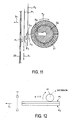
- the aiding structure 6 adopts the four kinds of control states shown in FIGS. 12 to 15 and operates according to the flow chart shown in FIG. 16 . Further, the aiding structure 6 controls the "rotational speed" (the direction included) of the aiding roller 51 and the "existence of negative pressure", thereby adopts the four kinds of control states aforementioned. The aiding structure 6 controls the "rotational speed” by the AC servomotor 55 and controls the "existence of negative pressure" by switching the electromagnetic valve 59.
- the aiding roller 51 rotates at an angular velocity of ⁇ in the take-out direction T1 of the postal matter P, and the electromagnetic valve 59 is opened, and a negative pressure is generated to one postal matter P supplied to the take-out position 20.
- the postal matter P1 in contact with the aiding roller 51 is absorbed to the peripheral surface of the aiding roller 51 and is pressed in the direction of the arrow T1 at a fixed speed in synchronization with the rotation of the aiding roller 51.
- the aiding roller 51 rotates at a fixed angular velocity of ⁇ in the take-out direction T1 of the postal matter P, and the electromagnetic valve 59 is closed, and the negative pressure is turned off.
- the first postal matter P1 does not always move at the speed synchronized with the rotation of the aiding roller 51. Namely, in this state, the concerned postal matter P can move quickly or slowly under the influence of other elements.
- the aiding roller 51 stops or rotates at a fixed angular velocity in the opposite direction to the take-out direction T1, and the electromagnetic valve 59 is opened, and a negative pressure is generated.
- the second postal matter P2 is stopped or is fed in the opposite direction and is applied with breaks, thus the aiding structure 6 supports the separation from the first postal matter P1.
- the aiding roller 51 stops or rotates at a fixed angular velocity in the take-out direction T1, and the electromagnetic valve 59 is closed, and the negative pressure is turned off, thus the aiding structure 6 contributes to forming of a gap between the trailing edge of the preceding first postal matter P1 and the trailing edge of the second postal matter P2 in contact with the aiding roller 51 and discharges the second postal matter P2 with weak force.
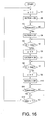
- the aiding structure 6, as shown in FIG. 16 on the basis of the information from the sensor 11 and the length range information of the postal matter P to be processed, shifts the postal matter P between the first to fourth control states aforementioned, thereby performs efficiently the take-out and separation operations of the plurality of postal matter P which are inserted in a batch.
- the aiding roller 51 at the start time of the take-out operation of the postal matter P, adopts the first control state ( FIG. 12 ). Namely, the aiding structure 6 generates a negative pressure on the peripheral surface of the aiding roller 51 and rotates it in the forward direction (Steps S1, S2). And, it monitors the output of the sensor 11 and at the point of time when the output signal of the sensor 11 becomes "dark (the state that the postal matter P blocks off the optical axis of the sensor)" (YES at Step S3), shifts to the second control state ( FIG. 13 ). Namely, at this point of time, the aiding structure 6 closes the electromagnetic valve 59 and eliminates the negative pressure (Step S4).
- the aiding structure 6 shifts to the third control state ( FIG. 14 ). Namely, at this time, the aiding structure 6 stops or rotates backward the aiding roller 51 (Step S6) and generates a negative pressure (Step S7).
- the aiding structure 6 shifts to the fourth control state ( FIG. 15 ). Namely, at this time, the aiding structure 6 stops or rotates forward the aiding roller 51 (Step S9), closes the electromagnetic valve 59, and eliminates the negative pressure (Step S10).
- the aiding structure 6 monitors the sensor 11 and after the output of the sensor 11 becomes "light" (YES at Step S11) and furthermore the fixed period of time T1 elapses (YES at Step S12), returns to the first control state at Step S1 ( FIG. 12 ), and then, until a stop command is issued from the host control system, continues the processes at Steps S1 to S12.
- the aiding structure 6 is installed in the neighborhood of the take-out position 20 of the postal matter P, so that it can support the take-out and separation operations of the postal matter P, can respond to the high speed process of the postal matter P, and can increase the throughput. Further, the aiding structure 6 can control the negative pressure and absorb the postal matter P to the aiding roller 51, so that the aiding roller 51 can use a metallic roller and can be operated stably over a long period of time.
- the postal matter P set in the insertion portion 2 are fed in the direction of the arrow F shown in the drawing by the supply structures 8a, 8b, and 9 and are pulled near the take-out position 20 one by one by the suction structure 4.
- the suction structure 4 is installed, even if the supply force of the postal matter P by the supply structures 8a, 8b, and 9 is small, the first postal matter P can be arranged quickly at the take-out position 20.
- the conveying state is disordered at the speed connection portion and the conveying position of the postal matter P is varied. Further, as V is reduced, the number of postal matter P discharged from the insertion portion 2 per unit time is reduced, so that the throughput is lowered.
- the initial speed of the take-out belt 23 is set to a value close to Va, and for example, the timing that the preceding postal matter P is pulled out by the conveying structure 7 using the sensor 11 and the speed becomes Va is obtained, and the speed of the take-out belt 23 is reduced at this timing and is reaccelerated to the initial speed Va at the timing that the necessary gap is formed.
- the sensor 11 is installed to monitor passing of the leading edge or trailing edge of the postal matter P and the gap between the postal matter P. In the take-out control, these information can be used or triggered.
- a control signal of the AC servomotor 24 when it is intended to apply acceleration and deceleration control to the take-out belt 23, thereby form a more appropriate gap and a control signal of an electromagnetic valve when it is intended to install the electromagnetic valve in the pipes 22a and 58 connected to the vacuum pumps 22 and 57 and control existence of air suction may be considered.
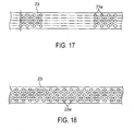
- the take-out belt 23 of the type shown in FIG. 17 is composed of the areas including many absorbing holes 23a in the longitudinal direction thereof and the areas including no absorbing holes 23a at all which are lined up alternately and the take-out belt 23 of the type shown in FIG. 18 is composed of many absorbing holes 23a continued in the longitudinal direction thereof.
- the gaps between the postal matter P can be hardly formed, so that it is necessary to turn on or off the absorption operation by the take-out structure 3 and form gaps mutually between the postal matter P.
- control method for the electromagnetic valve for example, a way of using the sensor 11, when one postal matter P is taken out, and the optical axis of the sensor 11 is blocked, and "dark" is generated, turning on the electromagnetic valve (the electromagnetic valve is closed), stopping the discharge operation, thereby standing by the take-out of the next postal matter P, when the output of the sensor 11 becomes "light” (the state of no postal matter P) or at the timing that appropriate gaps are formed between the postal matter, turning off the electromagnetic valve (the electromagnetic valve is opened), and taking out the next postal matter may be considered.
- the information of a plurality of rows of the sensors 11 is used as a control signal and on the basis of the finer and more correct position information of the postal matter P, the acceleration and deceleration control for the take-out belt 23 and the on-off control for the electromagnetic valve are repeated.
- FIGS. 19 and 20 an operation illustration for explaining the operation of the suction structure 4 aforementioned.
- FIGS. 19 and 20 a drawing of the take-out position 20 between the insertion portion 2 and the chamber 26 which is viewed from the downstream side of the postal matter P in the take-out direction.
- the supply force of the postal matter P by the floor belts 8a and 8b and the backup plate 9 is set comparatively weak. Therefore, the postal matter P moved in the direction of the arrow F in the state that the lower end thereof is in contact with the floor belts 8a and 8b, generally as shown in the drawing, in the posture that the lower end side precedes the upper end side, that is, in the state that the upper end inclines toward the backup plate 9 (the upstream side in the moving direction), is moved toward the take-out position 20.
- the suction structure 4 permits an air current to act and as shown by the arrow in FIG. 20 , raises the fallen postal matter P, and permits the surface of the postal matter P to face the take-out belt 23 in an area as wide as possible.
- a negative pressure can act sufficiently on the concerned postal matter P via the absorbing holes 23a of the take-out belt 23 and the postal matter P can be absorbed to the take-out belt 23 surely and stably.
- the suction structure 4 permits the air current to act on the postal matter P closest to the take-out position 20, raises the fallen postal matter P, and permits it to face the take-out belt 23, almost all the postal matter P can be permitted to surely face the take-out belt 23 without being pressed to it and can be absorbed, and the take-out operation of the postal matter P can be stabilized, and the processing efficient can be enhanced.
- the suction structure 4 permits the air current to act on the postal matter P closest to the take-out position 20, raises the fallen postal matter P, and permits it to face the take-out belt 23, almost all the postal matter P can be permitted to surely face the take-out belt 23 without being pressed to it and can be absorbed, and the take-out operation of the postal matter P can be stabilized, and the processing efficient can be enhanced.
- the fallen postal matter P cannot be raised normally.
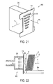
- the conveying guide 13 arranged opposite to the opening of the chamber 26 (suction chamber) of the absorption structure 60 of this embodiment has a plurality of holes 61 different in the opening area.
- a plurality of holes 13a in the same shape (opening area) are formed in the conveying guide 13, while in this embodiment, the holes 61 are made different in the shape such that the holes 61 slowly increase in the opening area in the ascending order of locations.
- the flow rate of the air current acting on the postal matter P supplied to the take-out position 20 opposite to the conveying guide 13 can be made different in the height direction in the surface of the concerned postal mater and as shown in FIG. 22 , on the neighborhood of the upper end of the postal matter supplied to the take-out position 20 which is away from the floor belts 8a and 8b, a stronger air current can act.
- the raising speed of the ordinary light postal matter P can be increased and the processing speed can be increased.
- the length of the holes 61 of the conveying guide 13 is increased slowly in the ascending order of locations and the opening area is made different, though for example, as shown in FIG. 23 , it is possible to change the arrangement density of many holes 62 in the same shape and make the flow rate of the air current acting in the surface of the postal matter P supplied to the take-out position 20 different.
- FIG. 24 the constitution of the essential section of a suction structure 70 relating to still another embodiment which can quickly raise the fallen postal matter P is shown.
- the conveying guide 13 having a plurality of holes 13a in the same shape which is explained in FIG. 5 , the internal structure of the chamber 25 is advised.
- a partition wall 71 is arranged in the chamber 26.
- the partition wall 71 is not installed, as shown in the drawing, if air is sucked in from the lower part of the chamber 26, air is sucked in from the lower holes 13a close to the suction source prior to the upper holes 13a and the flow rate of air of the former is higher than that of the latter.
- the partition wall 71 is installed.
- the partition wall 71 is installed in the chamber 26 and the flow path of air is formed is explained, though it is possible, in place of installation of the partition wall 71, to arrange the suction port of the chamber 26 upward. Further, it is possible to make the shape of the holes 13a of the conveying guide 13a equal to the shape (61 or 62) shown in FIG. 21 or 23 .
- the suction position by the suction structure 4 may be shifted to another place.
- a plurality of suction holes 81 are formed in the guide 14 of the take-out structure 3 opposite to the take-out position 20 across the take-out belt 23 .
- the plurality of slits 14a aforementioned for generating a negative pressure in the absorbing holes 23a of the take-out belt 23 are formed, though the plurality of holes 81 are formed above the slits 14a, that is, at the position off the take-out belt 23 upward in the drawing.
- the chamber 26 of the suction structure 4 are extended up to the back of the holes 81 and an air current for attracting the postal matter P to the take-out position 20 via the plurality of holes 81 is generated. Namely, the suction position by the suction structure 4 is set above the suction position of the take-out belt 23.
- the negative pressure acting on the postal matter P via the absorbing holes 23a of the take-out belt 23 functions so as to absorb the postal matter P to the take-out belt 23, while the air current acting on the postal matter P via the plurality of holes 81 of the guide 14 functions so as to pull the postal matter P near the take-out position 20.
- the vacuum pump 22 (the negative pressure generation structure) for generating a comparatively strong absorbing force for absorbing the postal matter P to the take-out belt 23 generates a high negative pressure and acts the suction force on the postal matter P
- the blower 27 (the suction apparatus) for generating an air current for pulling the postal matter P near the take-out position 20 sucks a large amount of air at a comparatively low negative pressure.
- the air current for absorbing the postal matter P in the neighborhood of the absorbing position of the take-out belt 23 and above the take-out belt 23 is generated, thus the fallen postal matter P can be raised at the absorbing position of the take-out belt 23 and the absorbance stability for the take-out belt 23 can be enhanced.
- the plurality of holes 81 for sucking are installed at the position off upward the take-out belt 23, though a plurality of holes 82 (described later) passing through the guide 14 may be formed under the take-out belt 23.
- the holes 81 of the guide 14 are used together with the plurality of holes 61 (62) of the suction structure 60 explained by referring to FIG. 21 ( FIG. 23 ) which are different in the opening area (density), the postal matter P can be raised surer and stabler and quickly and it is more preferable for stabilization of the take-out operation of the postal matter P.
- the embodiment for detecting the inclined state of the postal matter P at the leading edge in the moving direction which is supplied to the take-out position 20 by the supply structures 8a, 8b, and 9 and on the basis of the detection results, controlling turning on or off the air current by the suction structure 4 will be explained by referring to FIGS. 26 to 31 .
- the conveying guide 13 of the suction structure 4 the conveying guide 13 having the plurality of holes 61 different in the shape which are explained in FIG. 21 is used.
- two sensors 91 and 92 (a posture detection portion) for detecting the inclined state of the postal matter P at the leading edge in the moving direction are arranged.
- the sensor 91 having an optical axis passing near the upper end of the postal matter P supplied to the take-out position 20 and the sensor 92 having an optical axis passing in the neighborhood of the lower end are installed:
- a hole opening and closing structure 110 for selectively opening or closing the plurality of holes 61 of the guide 13 is installed between the conveying guide 13 of the suction structure 4 and the opening of the chamber 26 .
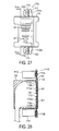
- the hole opening and closing structure 110 includes an upper hole closing plate 111 for simultaneously opening and closing the three holes 61 having a comparatively large opening area which is formed above the conveying guide 13, a lower hole closing plate 112 for simultaneously opening and closing the three holes 61 having a comparatively small opening area which is formed under the conveying guide 13, two stepping motors 113 and 114 for driving the hole closing plates 111 and 112 stepwise between the two positions of the open position and closed position, and pinion gears 115 and 116 for transferring the drive forces of the stepping motors 113 and 114 respectively to the hole closing plates 111 and 112.
- FIGS. 27 and 28 are the states that holes 111a and 112a of the hole closing plates 111 and 112 are overlaid so as to coincide with the holes 61 of the conveying guide 13 and the air current can act on the postal matter P at the take-out position 20 via all the holes 61.
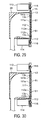
- FIG. 29 shows the state that the hole 111a of the upper hole closing plate 111 is slid to the open position where it is connected to the corresponding hole 61 of the conveying slide 13 and the lower hole closing plate 112 is slid to the closed position where the corresponding hole 61 of the conveying slide 13 is blocked and in this state, only on the neighborhood of the upper end of the postal matter P supplied to the take-out position 20, the air current can act.
- FIG. 29 shows the state that the hole 111a of the upper hole closing plate 111 is slid to the open position where it is connected to the corresponding hole 61 of the conveying slide 13 and the lower hole closing plate 112 is slid to the closed position where the corresponding hole 61 of the
- FIG. 30 shows the state that the upper hole closing plate 111 is slid to the closed position where the corresponding hole 61 of the conveying slide 13 is blocked and the hole 112a of the lower hole closing plate 112 is slid to the open position where it is connected to the corresponding hole 61 of the conveying slide 13 and in this state, only on the neighborhood of the lower end of the postal matter P supplied to the take-out position20, the air current can act.
- a plurality of slotted holes 111b and 112b for receiving a plurality of pins 13b projected from the conveying guide 13 so as to slide vertically are formed and the hole closing plates 111 and 112 can slide in the direction that they mutually separate and make contact, that is, in the vertical direction.
- racks 111c and 112c meshing with the pinion gears 115 and 116 attached to the rotary shafts of the stepping motors 113 and 114 aforementioned are formed and by driving the motors 113 and 114, the hole closing plates 111 and 112 can be moved between the closed position and the open position.
- the slotted holes 111b and 112b of the hole closing plates 111 and 112 are extended in the direction crossing the longitudinal direction of the plurality of holes 61 of the conveying guide 13.
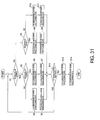
- the controller of the take-out apparatus 1 controls to open and close the two hole closing plates 111 and 112 of the hole opening and closing structure 110.
- the controller monitors the output of the sensors 91 and 92 and judges the posture of the postal matter P at the leading edge in the moving direction which is supplied toward the take-out position 20 by the supply structures 8a, 8b, and 9 (Steps S1, S2, S3).
- the controller on the basis of the output of the sensors 91 and 92, detects the inclined state of the postal matter P supplied to the take-out position 20. Further, the processes at Steps S1 to S3 are executed for each take-out of one postal matter P by the take-out structure 3.
- the controller on the basis of the output of the two sensors 91 and 92, so as to permit many air currents to act on the neighborhood of the upper end of the postal matter P and raise positively the postal matter P, moves the upper hole closing plate 111 of the hole opening and closing structure 110 to the open position (Steep S4) and moves the lower hole closing plate 112 to the closed position (Step S5).
- the air current is generated using only the upper three holes, thus compared with the case that the air current is generated via all of the six holes 61, stronger suction force can act on the neighborhood of the upper end of the postal matter P, thus the postal matter P can be raised faster and surer.
- Step S1 to S3 when judging that the outputs of the two sensors 91 and 92 are dark (YES at Step S1, YES at Step S2), the controller judges that the postal matter P at the leading edge in the moving direction is supplied in the posture that it is almost parallel to the take-out position 20, moves the two hole closing plates 111 and 112 to the closed position (Steps S6, S7), and stops the suction by the suction structure 4.
- the controller judges that the postal matter P at the leading edge in the moving direction is in the posture that the upper end thereof is inclined on the downstream side in the moving direction, moves the upper hole closing plate 111 to the closed position (Step S8), and moves the lower hole closing plate 112 to the open position (Step S9).
- the controller can permit the air current to act only on the neighborhood of the lower end of the postal matter P closest to the take-out position 20 and can raise the fallen postal matter P in cooperation with the two floor belts 8a and 8b.
- Step S1 to S3 when judging that the two sensors 91 and 92 are light (NO at Step S1, NO at Step S3), the controller judges that no postal mater P arrives at the take-out position 20, moves the two hole closing plates 111 and 112 to the open position (Steps S10, S11), and sucks quickly the postal matter P closest to the take-out position 20 in the take-out position 20. At this time, it is possible to control the blower 27 so as to generate many air currents via the six holes 61.
- the controller continues the aforementioned operations at Steps S1 to S11 until the postal matter P in the insertion portion 2 are all gone (NO at Step S12), moves the two hole closing plates 111 and 112 respectively to the closed position (Steps S13, S14), and then finishes the operation.
- the posture of the postal matter P supplied to the take-out position 20 is detected, and the air current by the suction structure 4 is switched above and below, so that independently of the posture of the postal matter P supplied to the take-out position 20, it can face surely on the take-out belt 23, and the take-out operation of the postal matter P can be stabilized, and the processing efficiency can be enhanced.
- the hole opening and closing structure 110 is operated so as to move the two hole closing plates 111 and 112 between the open position and the closed position is explained, though the hole closing plates 111 and 112 are operated respectively by the stepping motors 113 and 114, so that the hole closing plates 111 and 112 can be moved easily to a halfway position between the open position and the closed position. If the movement of the hole closing plates 111 and 112 is stopped between the open position and the closed position like this, the opening area of the holes 61 of the conveying guide 13 can be adjusted optionally. In this case, for example, it is possible to arrange three or more sensors at the take-out position 20, detect the inclined state of the postal matter P supplied to the take-out position 20 more in detail, and adjust stepwise the flow rate of the air current acting on the concerned postal matter P.
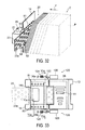
- the embodiment that the hole opening and closing structure 120 is attached to the holes 81 of the guide 14 of the take-out structure 3 which is explained already by referring to FIG. 25 will be explained by referring to FIGS. 32 to 37 .
- the case that only at the position off the take-out belt 23 of the guide 14 upward, the plurality of holes 81 are formed is explained, though here, also at the position off the take-out belt 23 of the guide 14 downward, the plurality of holes 82 are formed (refer to FIG. 33 ) and the hole opening and closing structure 120 is attached also to the holes 82.
- the guide 14 in place of the plurality of slits 14a aforementioned, one comparatively large and vertically long hole 14b (refer to FIG. 33 ) is formed.
- two sensors 93 and 94 for detecting the inclined state of the postal matter P at the leading edge in the moving direction are arranged.
- the sensor 93 installed upward in the drawing is arranged at the position where the optical axis passes in the neighborhood of the upper end of the postal matter P supplied to the take-out position 20 and the sensor 94 installed downward in the drawing is arranged at the position where the optical axis passes in the neighborhood of the lower end of the concerned postal matter P.
- the two sensors 93 and 94 function similarly to the sensors 91 and 92 which are explained by referring to Fig. 26 and function so as to detect the inclined state of the postal matter P supplied to the take-out position 20.
- a pressure sensor 95 is attached to the chamber 21 of the take-out structure 3.
- the pressure sensor 95 detects the inner pressure of the chamber 21, thereby detects the state of the negative pressure acting on the postal matter P via the many absorbing holes 23a of the take-out belt 23. More in detail, in the state that the postal matter P is normally absorbed into the absorbing holes 23a of the take-out belt 23, the inner pressure of the chamber 21 is lowered and the degree of vacuum is increased, while in the state that the postal matter P is not absorbed sufficiently into the absorbing holes 23a of the take-out belt 23, the inner pressure of the chamber 21 is kept high straight and the degree of vacuum is kept low straight.
- the inner pressure of the chamber 21 detected by the pressure sensor 95 is lower than a preset threshold value (the degree of vacuum is high), it can be judged that the postal matter P is normally absorbed to the take-out belt 23, while when the inner pressure of the chamber 21 is higher than the preset threshold value (the degree of vacuum is low), it can be judged that the postal matter P is not absorbed normally to the take-out belt 23.
- a preset threshold value the degree of vacuum is high
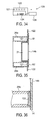
- the hole opening and closing structure 120 includes an upper structure for simultaneously opening and closing the plurality of upper holes 81 of the guide 14 of the take-out structure 3 and a lower structure for simultaneously opening and closing the plurality of lower holes 82 of the guide 14.
- the upper structure and lower structure have the same constitution, so that here, the lower structure shown in FIG. 34 will be explained as a representative.
- the hole opening and closing structure 120 includes a plurality of holes 121 in the shape almost coinciding with the holes 82 of the guide 14, a hole closing plate 122 for simultaneously opening and closing the plurality of holes 82 of the guide 14, and a solenoid 126 for moving the hole closing plate 122 in the direction of the arrow shown in the drawing against the pressing force of a tension spring 124.
- FIG. 34 the state that the solenoid 126 is turned on is shown.
- the opening portion of the chamber 26 of the suction structure 4, as shown in FIG. 35 is extended up to the back side of the upper holes 81 of the guide 14 of the take-out structure 3 and is extended up to the back side of the lower holes 82 of the guide 14.
- the negative pressure acts on the postal matter P at the take-out position 20 and via the upper holes 81 of the guide 14 opposite to the upper opening 26a where the chamber 26 of the suction structure 4 is extended and the lower holes 82 of the guide 14 opposite to the lower opening 26b of the chamber 26, the air current acts on the postal matter P at the take-out position 20.
- the opening of the chamber 26b extended under the suction structure 4 is arranged so as to be adhered closely to the back of the guide 14.
- the hole closing plate 122 is arranged slidably. For example, as shown in FIGS. 33 and 35 , if the solenoid 126 is turned on in the state that the holes 81 and 82 are opened and the hole closing plate 122 is slid on the innermost side of the sheet of paper in FIG. 36 , the plurality of holes 121 of the hole closing plate 122 are shifted from the plurality of holes 82 of the guide 14 and the hole closing plate 122 is moved to the closed position where the holes 82 are closed.
- the controller of the take-out apparatus 1 controls to open and close the two hole closing plates 122 of the hole opening and closing structure 120.
- the upper hole closing plate is assumed as 122a and the lower hole closing plate is assumed as 122b.
- the controller monitors the output of the sensors 93 and 94 and judges the posture of the postal matter P at the leading edge in the moving direction which is supplied toward the take-out position 20 by the supply structures 8a, 8b, and 9 (Steps S21, S22, S23).
- the controller on the basis of the output of the sensors 93 and 94, detects the inclined state of the postal matter P supplied to the take-out position 20. Further, the processes at Steps S21 to S23 are executed for each take-out of one postal matter P by the take-out structure 3.
- the controller on the basis of the output of the two sensors 93 and 94, so as to permit many air currents to act on the neighborhood of the upper end of the postal matter P and raise positively the postal matter P, moves the upper hole closing plate 122a of the hole opening and closing structure 120 to the open position (Steep S24) and moves the lower hole closing plate 122b to the closed position (Step S25).
- the postal mater P at the take-out position 20 can be sucked in toward the guide 14 of the take-out structure 3 and the concerned postal matter P can be absorbed satisfactorily to the take-out belt 23.
- the air current acts on the concerned postal matter P via the holes 81 above the take-out belt 23, so that the postal matter P can be brought directly close to the guide 14.
- Step S21 when judging that the outputs of the two sensors 93 and 94 are dark (YES at Step S21, YES at Step S22), the controller judges that the postal matter P at the leading edge in the moving direction is supplied in the posture that it is almost parallel to the take-out position 20 and refers to the output of the pressure sensor 95 of the take-out structure 3 (Step S26).
- Step S26 When judging at Step S26 that the degree of vacuum of the chamber 21 of the take-out structure 3 is sufficiently high (YES at Step S26), the controller judges that the postal matter P at the leading edge in the moving direction which is detected by the two sensors 93 and 94 is absorbed firmly to the take-out belt 23, moves the two hole closing plates 122a and 122b to the closed position (Steps S27, S28), and stops the suction by the suction structure 4.
- Step S26 when judging at Step S26 that the degree of vacuum of the chamber 21 of the take-out structure 3 is insufficient (NO at Step S26), the controller judges that the postal matter P at the leading edge in the moving direction which is detected by the two sensors 93 and 94 is not absorbed firmly to the take-out belt 23, moves the two hole closing plates 122a and 122b to the open position (Steps S29, S30), and continues the suction by the suction structure 4.
- a state may be considered that although the postal matter P at the leading edge in the moving direction is detected by the two sensors 93 and 94 and is supplied to the take-out position 20, the concerned postal matter P is not absorbed to the take-out belt 23 for some reason. Therefore, in such a case, it is possible to switch the suction by the blower to suction stronger than usual.
- Step S21 when judging that the output of the lower sensor 94 is light (NO at Step S21) and the output of the upper sensor 93 is dark (YES at Step S23), the controller judges that the postal matter P at the leading edge in the moving direction is in the state that the upper end thereof is inclined toward the downstream side in the moving direction, moves the upper hole closing plate 122a to the closed position (Step S31), and moves the lower hole closing plate 122b to the open position (Step S32). By doing this, the controller can permit the air current to act only on the neighborhood of the lower end of the postal matter P closest to the take-out position 20 and can raise the fallen postal matter P in cooperation with the two floor belts 8a and 8b.
- Step S21 to S23 when judging that the two sensors 93 and 94 are light (NO at Step S21, NO at Step S23), the controller judges that no postal mater P arrives at the take-out position 20, moves the two hole closing plates 122a and 122b to the open position (Steps S33, S34), and sucks quickly the postal matter P closest to the take-out position 20 in the take-out position 20.
- the controller continues the aforementioned operations at Steps S21 to S34 until the postal matter P in the insertion portion 2 are all gone (NO at Step S35), moves the two hole closing plates 122a and 122b respectively to the closed position (Steps S36, S37), and then finishes the operation.
- a step of judging whether the concerned postal matter P is absorbed to the take-out belt 34 or not using the pressure sensor 95 is added, so that when the postal matter P supplied to the take-out position 20 is not absorbed to the take-out belt 23, the air current by the suction structure 4 can act continuously on the postal matter P and the postal matter P can be absorbed surely to the take-out belt 23.
- the air current acts on the postal matter P at the take-out position 20 is explained, though if a sufficient amount of an air current can at on the postal matter P at the take-out position 20, the holes 61 of the conveying guide 13 may be omitted.
- the conveying guide 13 and guide 14 are formed by different members.
- the guides may be formed as an integrated guide 134.
- the take-out belt 23 opposite to the opening of the chamber 21 of the take-out structure 3 the negative pressure acts on the postal matter P at the take-out position 20 and via the upper holes 81' of the guide 134 opposite to the upper opening 26a where the chamber 26 of the suction structure 4 is extended, the air current may act on the postal matter P at the take-out position 20.
- the present invention is not limited straight to the aforementioned embodiments and at the execution stage, within a range which is not deviated from the objects thereof, the components can be modified and concreted. Further, by appropriate combinations of a plurality of components disclosed in the embodiments aforementioned, various inventions can be formed. For example, from all the components indicated in the aforementioned embodiments, some components may be eliminated. Furthermore, components extending over different embodiments may be combined appropriately.
- the sheet take-out apparatus of the present invention includes the aforementioned constitution and operation, so that the sheet take-out operation can be stabilized and the processing efficiency can be increased.
Landscapes
- Engineering & Computer Science (AREA)
- Mechanical Engineering (AREA)
- Sheets, Magazines, And Separation Thereof (AREA)
Abstract
Description
- The present invention relates to a sheet take-out apparatus for taking out sheets in the stacking state one by one in the surface direction.
- Conventionally, as an apparatus for taking out a plurality of sheets in a stacking state one by one, a sheet processing apparatus for moving the plurality of sheets in a stacking direction, conveying a sheet at one end to a take-out position, generating a negative pressure via holes of a belt standing by at the take-out position, absorbing the sheet, moving the belt in this state in a take-out direction, thereby taking out the absorbed sheet in a surface direction is known (for example, refer to Patent Document 1).
- The apparatus particularly detects the density of sheets conveyed to the take-out position and controls the conveying speed of the sheets conveyed to the take-out position according to the density of sheets. By doing this, the sheet take-out operation is stabilized and the processing efficiency is enhanced.
- However, even if the sheet conveying speed is controlled like this, it is entirely impossible that there are no tilt and gap between sheets conveyed to the take-out position and the belt, thus the sheets may not be absorbed stably to the belt, and the take-out operation may be unstable.
Patent Document 1: Japanese Patent Application2001-335165 - An object of the present invention is to provide a sheet take-out apparatus for stabilizing the sheet take-out operation and enhancing the processing efficiency.
- To accomplish the above object, the sheet take-out apparatus of the present invention includes an insertion portion to stack and insert a plurality of sheets in an upright state, a supply structure to move the plurality of inserted sheets in the stacking direction and supply a sheet at a leading edge in a moving direction to a take-out position at one end of the insertion portion, a take-out structure to rotate in contact with the sheet supplied to the take-out position, thereby take out the sheet in a direction almost perpendicular to the stacking direction, and a suction structure to permit an air current to act on the sheet at the leading edge in the moving direction which is supplied to the take-out position by the supply structure and absorbing the sheet toward the take-out position, wherein the suction structure, so as to raise the fallen sheet at the leading edge in the moving direction and permit it to face the take-out structure, makes the flow rate of the air current acting on the sheet different in the surface of the sheet.
- According to the present invention, the sheet supplied to the take-out position in the fallen state, by permitting an air current to act on it by the suction structure, faces the take-out structure, so that it is possible to permit the sheet to make contact with the take-out structure surely and stably, stabilize the sheet take-out operation, and enhance the processing efficiency.
- Further, the sheet take-out apparatus of the present invention includes an insertion portion to stack and insert a plurality of sheets in an upright state, a supply structure to move the plurality of inserted sheets in the stacking direction and supply the sheet at the leading edge in the moving direction to the take-out position at one end of the insertion portion, a take-out structure to rotate in contact with the sheet supplied to the take-out position, thereby take out the sheet in a direction almost perpendicular to the stacking direction, a suction structure to permit an air current to act on the sheet, supplied to the take-out position by the supply structure, at the leading edge in the moving direction and absorb the sheet toward the take-out position, and a posture detection portion to detect the posture of the sheet, supplied to the take-out position by the supply structure, at the leading edge in the moving direction, wherein the suction structure, according to the detection results by the posture detection portion, switches a position to permit the air current to act on the sheet at the leading edge in the moving direction.
- According to the present invention, in accordance with the posture of the sheet at the leading edge in the moving direction which is supplied to the take-out position, the position for permitting the air current to act on the sheet by the absorbing structure is switched, so that even when the sheet is supplied to the take-out position in any posture, it can face surely the take-out structure.
- Furthermore, the sheet take-out apparatus of the present invention includes an insertion portion to stack and insert a plurality of sheets in an upright state, a supply structure to move the plurality of inserted sheets in the stacking direction and supply a sheet at a leading edge in a moving direction to the take-out position at one end of the insertion portion, a take-out structure to rotate in contact with the sheet supplied to the take-out position, thereby take out the sheet in the almost horizontal direction almost perpendicular to the stacking direction, and a suction structure to permit an air current to act on the sheet, supplied to the take-out position by the supply structure, at the leading edge in the moving direction and absorb the sheet toward the take-out position, wherein the supply structure supplies the sheet at the leading edge in the moving direction toward the take-out position in a posture that the upper end thereof is inclined toward an upstream side in the moving direction, and the suction structure, via holes arranged above the position where the take-out structure makes contact with the sheet supplied to the take-out position, permits an air current to act on the neighborhood of the upper end of the inclined sheet at the leading edge in the moving direction, raises the sheet, and permits it to face the take-out structure.
- According to the aforementioned invention, via the holes arranged above the position where the take-out structure makes contact with the sheet at the leading edge in the moving direction which is supplied to the take-out position, the suction structure permits the air current for sucking the sheet to act on the sheet, so that the take-out structure and the concerned sheet can make contact with each other at the position where the suction structure sucks the sheet to the take-out position, and the sheet at the leading edge in the moving direction can face surely the take-out structure
-
-
FIG. 1 is a block diagram showing the constitution of the postal matter processing apparatus relating to the embodiments of the present invention. -
FIG. 2 is a schematic view showing the constitution of the take-out apparatus incorporated in the processing apparatus shown inFIG. 1 . -
FIG. 3 is a partially enlarged perspective view showing the constitution of the essential section of the take-out structure of the take-out apparatus shown inFIG. 2 which is enlarged partially. -
FIG. 4 is a partially enlarged perspective view showing the state that the belt is removed from the constitution shown inFIG. 3 . -
FIG. 5 is a partially enlarged perspective view of the essential section of the suction structure incorporated in the take-out apparatus shown inFIG. 2 which is enlarged partially. -
FIG. 6 is a partially enlarged cross sectional view of the essential section of the separation structure incorporated in the take-out apparatus shown inFIG. 2 which is enlarged partially. -
FIG. 7 is a partially enlarged cross sectional view of the constitution shown inFIG. 6 which is cut along the cutaway line VII-VII. -
FIG. 8 is a partially enlarged cross sectional view for explaining the behavior of the separation roller and postal matter in the state that one postal matter is conveyed on the conveying path. -
FIG. 9 is a partially enlarged cross sectional view showing one postal matter taken out on the conveying path in the bent state. -
FIG. 10 is a schematic view showing the take-out apparatus with the absorption chamber opposite to the separation roller added. -
FIG. 11 is a partially enlarged cross sectional view for explaining the behavior of the separation roller and postal matter in the state that two pieces of postal matter are conveyed on the conveying path in the stacking state. -
FIG. 12 is a schematic view for explaining the first control state of the aiding structure. -
FIG. 13 is a schematic view for explaining the second control state of the aiding structure. -
FIG. 14 is a schematic view for explaining the third control state of the aiding structure. -
FIG. 15 is a schematic view for explaining the fourth control state of the aiding structure. -
FIG. 16 is a flow chart for explaining the first to fourth control operations by the aiding structure. -
FIG. 17 is a partially enlarged view showing the take-out belt having intermittent absorbing holes in the longitudinal direction. -
FIG. 18 is a partially enlarged view showing the take-out belt having continuous absorbing holes in the longitudinal direction. -
FIG. 19 is an operation illustration for explaining the operation by the suction structure. -
FIG. 20 is an operation illustration for explaining the operation by the suction structure. -
FIG. 21 is a perspective view showing an embodiment different in the opening area of the conveying guide holes of the suction structure. -
FIG. 22 is an operation illustration for explaining the operation by the suction structure shown inFIG. 21 . -
FIG. 23 is a perspective view showing another embodiment of the suction structure shown inFIG. 21 . -
FIG. 24 is an operation illustration for explaining the operation of the suction structure in another embodiment. -
FIG. 25 is a perspective view showing an embodiment in which suction holes are formed in the guide of the take-out structure. -
FIG. 26 is a perspective view for explaining the constitution for detecting the posture of postal matter supplied to the take-out position. -
FIG. 27 is a schematic view showing the hole opening and closing structure attached to the conveying guide of the suction structure. -
FIG. 28 is a cross sectional view along the line V28 - V28 shown inFIG. 27 . -
FIG. 29 is a cross sectional view showing the state that the upper hole closing plate is moved to the open position by the hole opening and closing structure shown inFIG. 27 and the lower hole closing plate is moved to the closed position. -
FIG. 30 is a cross sectional view showing the state that the upper hole closing plate is moved to the closed position by the hole opening and closing structure shown inFIG. 27 and the lower hole closing plate is moved to the open position. -
FIG. 31 is a flow chart for explaining the control operation of the hole opening and closing structure shown inFIG. 27 on the basis of the sensor output shown inFIG. 26 . -
FIG. 32 is a perspective view for explaining the constitution for detecting the posture of postal matter supplied to the take-out position. -
FIG. 33 is a schematic view showing the hole opening and closing structure for opening and closing the suction holes formed in the guide of the take-out structure. -
FIG. 34 is a schematic view showing the hole opening and closing structure shown inFIG. 33 . -
FIG. 35 is a cross sectional view along the line V35 -V35 shown inFIG. 33 . -
FIG. 36 is a partially enlarged cross sectional view along the line V36 -V36 shown inFIG. 33 . -
FIG. 37 is a flow chart for explaining the control operation of the hole opening and closing structure shown inFIG. 33 . -
FIG. 38 is a perspective view showing still another embodiment of the suction structure shown inFIG. 23 . -
FIG. 39 is a perspective view showing the suction structure and take-out structure shown inFIG. 38 . - Hereinafter, the embodiments of the present invention will be explained in detail with reference with the accompanying drawings.
-
FIG. 1 shows a block diagram of the schematic structure of a postal matter processing apparatus 100 (hereinafter, referred to as just a processing apparatus 100) including a sheet take-out apparatus 1 (hereinafter, referred to as just a take-out apparatus 1) relating to the embodiments of the present invention. Theprocessing apparatus 100, in addition to the take-out apparatus 1, includes adiscriminator 102, arejection portion 104, a switch-back portion 106, and astacker 108. Further, sheets processed by theprocessing apparatus 100 of this embodiment are postal matter, though processed media (that is, sheets) are not limited to postal matter. - Postal matter is set in the take-
out apparatus 1 in the stacking state and since the take-out apparatus 1 is operated as described later, is taken out one by one onto aconveying path 101. On theconveying path 101, a plurality of sets of endless conveying belts not drawn are extended so as to hold theconveying path 101 and the postal matter is held and conveyed between the conveying belts. - The postal matter taken out on the conveying
path 101 passes through thediscriminator 102 and here, various information is read from the postal matter. Thediscriminator 102, on the basis of the read various information, discriminates the conveying posture and sorting destination of the postal matter. Particularly, thediscriminator 102 reads the destination information such as the zip code and address which are written on each postal matter and discriminates the sorting destination. - The postal matter passing through the
discriminator 102 is distributed in the conveying direction thereof via a gate G1. Namely, the postal matter which is discriminated as postal matter to be rejected by thediscriminator 102 is conveyed to therejection portion 104 via the gate G1 and the other postal matter is conveyed to thestacker 108 via the gate G1. - At this time, when the
discriminator 102 discriminates that the concerned postal matter must be reversed in the conveying direction, the postal matter is fed to the switch-back portion 106 via a gate G2 and the conveying direction is reversed here. The postal matter which does not need to be reversed in the conveying direction makes a detour to the switch-back portion 106 via the gate G2 and is conveyed to thestacker 108. - The postal matter fed to the
stacker 108 on the conveyingpath 101 is sorted and stacked in a sorting and stacking pocket not drawn according to the discrimination results by thediscriminator 102.
The postal matter sorted and stacked in each sorting and stacking pocket is stacked in the state that the top and bottom thereof are arranged properly. -
FIG. 2 shows a plan view showing the take-outapparatus 1 relating the embodiments of the present invention which is viewed from above.
The take-out apparatus 1 includes an insertion portion 2 for inserting a plurality of sheets P in the stacking state, a supply structure (described later) for moving the plurality of inserted sheets P in the stacking direction and supplying the sheet at the leading edge in the moving direction to a take-out position 20, a take-out structure 3 for feeding the postal matter P supplied to the take-out position 20 in the surface direction thereof and taking out it on a conveying path 10 which will be described later, a suction structure 4 for taking out, among the postal matter inserted via the insertion portion 2, the postal matter P at the leading edge and sucking it toward the take-out position 20, a separation structure 5 for separating the second and subsequent postal matter P which are taken out following the postal matter P taken out from the take-out position 20, an aiding structure 6 for permitting a negative pressure to act on the postal matter P supplied to the take-out position 20 on the upstream side of the take-out structure 3, moving it in both forward and backward directions, thereby aiding the take-out operation, and a conveying structure 7 for pulling out the postal matter P passing through the separation structure 5 at a slightly faster speed than the take-out speed and conveying it toward the downstream side. - Further, the take-out
apparatus 1 includes asensor 11 for detecting passing of the postal matter P taken out from the take-outposition 20 at one end of theinsertion portion 2 onto the conveyingpath 10 and a plurality of conveyingguides 12 to 18. Thesensor 11 includes a light emission portion and a light receiving portion so as to hold the conveyingpath 10 through which the postal matter P passes and when the optical axis thereof is blocked off by the postal matter P, detects passing of the concerned postal matter P. In this embodiment, thesensors 11 are arranged in a plurality of rows in the perpendicular direction to the sheet of paper on whichFIG. 2 is drawn or a line sensor composed of elements lined up in the perpendicular direction to the sheet of paper are arranged. Further, the plurality of conveyingguides 12 to 18 guide the movement and conveyance thereof by making contact with the end side and surface of the postal matter P. - Into the
insertion portion 2, a plurality of postal mater P are inserted together in the stacking state and in the upright state. On the bottom of theinsertion portion 2, twofloor belts FIG. 2 ) are arranged. Further, among the plurality of postal matter P, at the position facing the postal matter P at the trailing edge in the moving direction, abackup plate 9 simply connected to thefloor belt 8b (one of the two) for moving in the direction of the arrow F in cooperation with it, thereby supplying the postal matter P at the leading edge in the moving direction to the take-outposition 20 is arranged. Namely, the twofloor belts backup plate 9 function as a supply structure of the present invention. - Further, the conveying
guide 18 is extended to the position for specifying one side of theinsertion portion 2 in the direction of the arrow F and guides the end side of each of the postal matter P. Further, the conveying guides 12, 13, and 14 are arranged in line with each other along the take-outposition 20 on one end side of theinsertion portion 2, function so as to stop the postal matter P at the leading edge in the moving direction which is supplied in the direction of the arrow F at the take-outposition 20, and function so as to guide the postal matter P taken out from the take-outposition 20 in contact with one side thereof. - The take-out
structure 3 includes achamber 21, theguide 14, and a vacuum pump 22 (or an equivalent article). Further, the take-outstructure 3 includes an endless take-outbelt 23 that at least the part of a fixed area moves in the direction of an arrow T1 (the take-out direction of the postal matter P) shown in the drawing along the take-outposition 20 and amotor 24 for driving the take-outbelt 23. The take-outbelt 23, so that at least one part thereof moves in the direction of the arrow T1 shown in the drawing along the take-outposition 20 and the conveyingpath 10 continued from the take-outposition 20, is wound with a plurality ofrollers 25, stretched, and positioned. - The
guide 14 is arranged at the position opposite to the take-outposition 20 so as to hold the belt inside the take-outbelt 23. Thechamber 21 is arranged on the back side of theguide 14, that is, at the position opposite to the take-outposition 20 by holding the take-outbelt 23 and theguide 14. The take-outbelt 23, as shown inFIG. 3 by partially enlarged, has many absorbingholes 23a.
Further, theguide 14, as shown inFIG. 4 , in the moving direction T1 of the take-out belt 23 (that is, the take-out direction of the postal matter P), has a plurality of long andnarrow slits 14a. - And, if the
vacuum pump 22 is operated and thechamber 21 is evacuated, via the opening (not drawn) of thechamber 21 opposite to theguide 14, the plurality ofslits 14a of theguide 14, and the many absorbingholes 23a of the take-outbelt 23 moving in the direction of the arrow T1, a negative pressure (an arrow S1 shown in the drawing) acts on the postal matter P supplied to the take-outposition 20 and the postal matter P is absorbed to the surface of the take-outbelt 23 and in correspondence with movement of the take-outbelt 23, is taken out from the take-outposition 20 onto the conveyingpath 10. - In this case, the absorbing force by the
vacuum pump 22 in the direction of the arrow S1 is set so that the conveying force for discharging the first postal matter P absorbed to the take-outbelt 23 in the take-out direction T1 is at least larger than the frictional force acting between the first sheet and the second sheet. The take-outstructure 3, basically, separates the postal matter P at the take-outposition 20 one by one and discharges them onto the conveyingpath 10, though sheets which are discharged onto the conveyingpath 10 in the stacking state of a plurality of sheets are separated one by one by theseparation structure 5 which will be described later. - The
suction structure 4 includes achamber 26 arranged on the back side of the conveyingguide 13 for the take-outposition 20 and a blower 27 (or an equivalent article) for sucking air in thechamber 26. Thechamber 26, between the take-outstructure 3 aforementioned and the aidingstructure 6 which will be described later, is arranged in the neighborhood of the take-outposition 20 in the posture that the opening thereof not drawn is opposite to the back of theguide 13. Further, theguide 13, as shown inFig. 5 as partially enlarged, has a plurality ofholes 13a in accordance with the width of the opening of thechamber 26. In other words, the plurality ofholes 13a are arranged in the opening of thechamber 26. - And, if the
blower 27 is operated and the air in thechamber 26 is sucked, an air current is generated in the direction of an arrow B1 shown in the drawing via the plurality ofholes 13a of theguide 13 and among a plurality of postal matter P inserted into theinsertion portion 2, the postal matter P nearest to the take-outposition 20 is sucked toward the take-outposition 20. After the postal matter P sucked to the take-outposition 20 is taken out, the next postal matter P is sucked toward the take-outposition 20. Namely, by installation of thesuction structure 4, the postal matter P to be taken out next can be supplied quickly to the take-outposition 20 and even if the supply force by thesupply structures position 20. By doing this, the aforementioned take-out operation of the postal matter P by the take-outstructure 3 can be quickened. - The
separation structure 5, for the conveyingpath 10 extended on the downstream side (downward inFIG.2 ) of the take-outposition 20, is installed on the opposite side of the take-outstructure 3. Theseparation structure 5, by permitting a negative pressure to act on the postal matter P conveyed on the conveyingpath 10 from the opposite side of the take-outstructure 3, gives separation torque in the opposite direction to the take-out direction of the postal matter P to it. Namely, if theseparation structure 5 is operated, even when, following the postal matter P taken out from the take-outposition 20, the second and subsequent postal matter P (three or more pieces of postal matter may be taken out in the stacking state) are taken out, the second and subsequent postal matter P are stopped by the negative pressure and separation torque or are returned in the opposite direction and are separated from the first postal matter P. - More in detail, the
separation structure 5, as shown inFIG. 6 as partially enlarged, has aseparation roller 31 installed rotatably in both forward and backward directions in the take-out direction T1 of the postal matter P. Theseparation roller 31, as shown also inFIG. 7 , is rotatably attached to the rotary shaft fixedly attached to the conveyingpath 10, that is, acylinder 32 having achamber 33, which will be described later, via abearing 34 and has many absorbingholes 31a passing through so as to connect the inner peripheral surface and outer peripheral surface. Theseparation roller 31 is formed by a rigid body of an almost cylindrical metallic material and is arranged at the position where the outer peripheral surface thereof is exposed onto the conveyingpath 10. Further, thecylinder 32 as a rotary shaft has thechamber 33 for generating a negative pressure and is positioned and fixed in the posture that anopening 33a of thechamber 33 faces the conveyingpath 10.FIG. 7 shows a cross section view along the broken line VII-VII shown in FIH. 6. - Further, the
separation structure 5 includes anAC servomotor 35 for rotating theseparation roller 31 at desired torque in both forward and backward directions and anendless timing belt 36 for transferring the drive force by themotor 35 to theseparation roller 31. Thetiming belt 36 is wound and stretched round apulley 35a fixed to the rotary shaft of themotor 35 and a pulley (not drawn) fixed to arotary shaft 31b (refer toFIG. 7 ) of theseparation roller 31. Furthermore, theseparation structure 5 has a vacuum pump 37 (or an equivalent article) connected to thechamber 33 of thecylinder 32 to which theseparation roller 31 is attached rotatably via apipe 38. - And, if the
vacuum pump 37 is operated and thechamber 33 is evacuated, via theopening 33a of thechamber 33 and among the many absorbingholes 31a of theseparation roller 31, a specificabsorbing hole 310 opposite to theopening 33a, a negative pressure (an arrow S2 shown in the drawing) acts on the surface of the postal matter P passing on the conveyingpath 10 and the postal matter P is absorbed to the outer peripheral surface of theseparation roller 31. In this case, when theseparation roller 31 is rotating, also to the postal matter P absorbed to the outer peripheral surface of theseparation roller 31, the conveying force in the rotational direction of theseparation roller 31 is given. Further, in the following description, the area where the negative pressure acts on the postal matter P via the absorbinghole 310 of theseparation roller 31 is referred to as a separation area As. - On the other hand, the
AC servomotor 35, basically, drives and controls theseparation roller 31 so as to give always fixed separation torque in the opposite direction (the direction of an arrow T2 shown in the drawing) to the take-out direction to theseparation roller 31. The separation torque, when conveying one postal matter P on the conveyingpath 10, is set so that theseparation roller 31 realizing absorption of one postal matter P can accompany the concerned postal matter P in the conveying direction and when taking out a plurality of postal matter P on the conveyingpath 10 in the stacking state, is set so that the second and subsequent postal matter P on the side of theseparation roller 31 are stopped or returned in the opposite direction and can be separated from the first postal matter P. - Namely, as shown in
FIG. 8 , when one postal matter P is taken out normally from the take-outposition 20 and is conveyed on the conveyingpath 10, conveying force F1 in the forward direction (the direction of the arrow T1) which is given to the concerned postal matter P by the take-outstructure 3 is larger than conveying force F2 in the opposite direction which is given to the postal matter P by theseparation roller 31 which is given the separation torque in the opposite direction (the direction of the arrow T2), thus the concerned postal matter P is conveyed in the forward direction T1 and theseparation roller 31 accompanies the postal matter P or is stopped or runs idle in the opposite direction to the take-out direction. - When the
separation roller 31 runs idle in the opposite direction, if fixed separation torque is given continuously, the rotational speed is slowly increased, thus the take-out of the postal matter P may be influenced adversely, so that in this embodiment, the reverse speed of theseparation roller 31 is given an upper limit. Concretely, it is set at the upper limit speed the absolute value of which is smaller than the take-out speed of the postal matter P. - In this embodiment, at the position where the concerned postal matter P is away from the position where the concerned postal matter P is absorbed to the take-out
belt 23, that is, the position where thechamber 21 is opposite to the take-outposition 20 on the downstream side in the take-out direction T1, there is the separation area As to which theseparation roller 31 is opposite, so that even if the negative pressure S1 by thechamber 21 is made sufficiently stronger than the negative pressure S2 by theseparation roller 31, it is highly possible that only one postal matter P conveyed is attracted to the side of theseparation roller 31 and makes contact with it. - In this case, for example, if the concerned postal matter P is thin postal matter P with low stiffness, as shown in
FIG. 9 , the return force in the opposite direction by theseparation roller 31 acts excessively on the postal matter P and as shown in the drawing, there is a possibility that the postal matter P may be broken. Therefore, as shown inFIG. 10 , it is desired to add achamber 41 at the position opposite to the separation roller 31 (the separation area As) inside the take-outbelt 23 and furthermore add avacuum pump 42 for evacuating thechamber 41. As mentioned above, if a negative pressure S3 in the direction toward the take-outbelt 23 acts on the postal matter P at the position opposite to the separation area As, the aforementioned problem of breaking as shown inFIG. 9 can be solved. - On the other hand, as shown in
FIG. 11 , when two postal matter P are taken out from the take-outposition 20 onto the conveyingpath 10 in the stacking state, the first postal matter P1 on the near side to the take-outbelt 23 is given the conveying force F1 aforementioned from the take-outstructure 3 and is conveyed in the forward direction T1 and the second postal matter P2 on the near side to theseparation roller 31 is given the conveying force F2 aforementioned in the opposite direction T2 from theseparation roller 31. At this time, between the two postal matter P1 and P2, frictional forces F3 and F4 act mutually in the opposite directions. The frictional forces F3 and F4 are generated when the two postal matter P1 and P2 are in contact with each other, though when the two are away from each other, they become a zero. - In either case, the conveying forces F1 and F2 acting on the two postal matter P1 and P2 are set at a value sufficiently larger than the maximum value of the frictional forces F3 and F4 generated between the two, so that the second postal matter P2 given the conveying force F2 in the opposite direction is returned in the opposite direction T2 to the take-out direction T1 and is separated from the first postal matter P1.
- As mentioned above, the
separation roller 31 is formed by a metallic roller, and the separation torque is given to the postal matter P taken out onto the conveyingpath 10, and the negative pressure acts on the postal matter P, so that compared with a conventional separation roller suing a rubber roller, theseparation roller 31 can lengthen greatly the use life span of the roller, can keep the separation capacity good for a long period of time, can respond to increasing of the processing speed of the postal matter P, thereby can increase the throughput. Further, when only one postal matter P is taken out, it is highly possible that theseparation roller 31 runs idle, so that except the case that a plurality of postal matter P are taken out in the stacking state (overlap feed), the separation torque given to theseparation roller 31 may be set to a zero. Namely, the separation torque is generally set at a zero and when the leading edge of the postal matter is detected by thesensor 11, the separation torque is given to theseparation roller 31. - Again in
FIG. 2 , the aidingstructure 6 arranged above thesuction structure 4 shown in the drawing, that is, on the upstream side of the postal matter P in the take-out direction T1 has a structure almost similar to that of theseparation structure 5 aforementioned. Namely, the aidingstructure 6 has an aidingroller 51 installed rotatably in both forward and backward directions in the take-out direction T1 of the postal matter P. - The aiding
roller 51 is attached rotatably to the rotary shaft fixedly installed opposite to the take-outposition 20, that is, acylinder 53 internally having a chamber and has may absorbingholes 52 passing through so as to connect the inner peripheral surface and the outer peripheral surface. Further, the aidingroller 51 is formed by a rigid body of an almost cylindrical metallic material and is arranged at the position where the outer peripheral surface thereof is exposed onto the take-outposition 20. Further, thecylinder 53 as a rotary shaft has a chamber for generating a negative pressure and is positioned and fixed in the posture that the opening of the chamber faces the take-outposition 20. - Further, the aiding
structure 6 includes anAC servomotor 55 for rotating the aidingroller 51 at desired torque in both forward and backward directions and anendless timing belt 56 for transferring the drive force by themotor 55 to the aidingroller 51. Thetiming belt 56 is wound and stretched round apulley 55a fixed to the rotary shaft of themotor 55 and a pulley (not drawn) fixed to the rotary shaft of the aidingroller 51. Furthermore, the aidingstructure 6 has a vacuum pump 57 (or an equivalent article) connected to the chamber of thecylinder 53 to which the aidingroller 51 is attached rotatably via apipe 58. And, halfway on thepipe 58, anelectromagnetic valve 59 for turning on or off the negative pressure is attached. - And, the aiding
structure 6 rotates and stops the aidingroller 51 at a desired speed in both forward and backward directions and turns on or off the negative pressure by thevacuum pump 57, thereby supports the take-out operation and separation operation of the postal matter P. For example, when taking out the postal matter P supplied to the take-outposition 20 by the take-outstructure 3, the aidingstructure 6 permits the negative pressure to act on the trailing edge of the postal matter P in the take-out direction, absorbs it, rotates it in the forward direction T1, thereby supports the take-out of the concerned postal matter P. By doing this, for example, when taking out large postal matter P comparatively heavy, it can give conveying force larger and stabler than that when taking out ordinary postal matter P, thus the take-out operation of the postal matter P can be stabilized. - Further, when the first postal matter P is taken out by the take-out
structure 3 and then the trailing edge of the postal matter P in the take-out direction comes out up to the position free of interference with the aidingroller 51, the aidingstructure 6 absorbs the trailing edge side of the second postal matter P supplied next to the take-out position to the aidingroller 51, gives the desired torque in the opposite direction, and applies breaks, thereby can prevent overlap feed of the postal matter P in cooperation with theseparation structure 5 aforementioned. In this case, the aidingstructure 6 controls the torque in the opposite direction given to the aidingroller 51 and controls the time for applying breaks, thereby can control the gap and pitch of the postal matter P to be taken out from the take-outposition 20 onto the conveyingpath 10. - Concretely, the aiding
structure 6 adopts the four kinds of control states shown inFIGS. 12 to 15 and operates according to the flow chart shown inFIG. 16 . Further, the aidingstructure 6 controls the "rotational speed" (the direction included) of the aidingroller 51 and the "existence of negative pressure", thereby adopts the four kinds of control states aforementioned. The aidingstructure 6 controls the "rotational speed" by theAC servomotor 55 and controls the "existence of negative pressure" by switching theelectromagnetic valve 59. - Firstly, in the first control state shown in
FIG. 12 , the aidingroller 51 rotates at an angular velocity of ω in the take-out direction T1 of the postal matter P, and theelectromagnetic valve 59 is opened, and a negative pressure is generated to one postal matter P supplied to the take-outposition 20. In this state, the postal matter P1 in contact with the aidingroller 51 is absorbed to the peripheral surface of the aidingroller 51 and is pressed in the direction of the arrow T1 at a fixed speed in synchronization with the rotation of the aidingroller 51. - Further, in the second control state shown in
FIG. 13 , that is, in the state that the leading edge of the first postal matter P1 reaches thesensor 11, the aidingroller 51 rotates at a fixed angular velocity of ω in the take-out direction T1 of the postal matter P, and theelectromagnetic valve 59 is closed, and the negative pressure is turned off. In this state, the first postal matter P1 does not always move at the speed synchronized with the rotation of the aidingroller 51. Namely, in this state, the concerned postal matter P can move quickly or slowly under the influence of other elements. - Further, in the third control state shown in
FIG. 14 , that is, in the state that the trailing edge of the first postal matter P1 in the take-out direction is off the position of interference with the aidingroller 51, the aidingroller 51 stops or rotates at a fixed angular velocity in the opposite direction to the take-out direction T1, and theelectromagnetic valve 59 is opened, and a negative pressure is generated. In this state, the second postal matter P2 is stopped or is fed in the opposite direction and is applied with breaks, thus the aidingstructure 6 supports the separation from the first postal matter P1. - Furthermore, in the fourth control state shown in
FIG. 15 , the aidingroller 51 stops or rotates at a fixed angular velocity in the take-out direction T1, and theelectromagnetic valve 59 is closed, and the negative pressure is turned off, thus the aidingstructure 6 contributes to forming of a gap between the trailing edge of the preceding first postal matter P1 and the trailing edge of the second postal matter P2 in contact with the aidingroller 51 and discharges the second postal matter P2 with weak force. - And, the aiding
structure 6, as shown inFIG. 16 , on the basis of the information from thesensor 11 and the length range information of the postal matter P to be processed, shifts the postal matter P between the first to fourth control states aforementioned, thereby performs efficiently the take-out and separation operations of the plurality of postal matter P which are inserted in a batch. - The aiding
roller 51, at the start time of the take-out operation of the postal matter P, adopts the first control state (FIG. 12 ). Namely, the aidingstructure 6 generates a negative pressure on the peripheral surface of the aidingroller 51 and rotates it in the forward direction (Steps S1, S2). And, it monitors the output of thesensor 11 and at the point of time when the output signal of thesensor 11 becomes "dark (the state that the postal matter P blocks off the optical axis of the sensor)" (YES at Step S3), shifts to the second control state (FIG. 13 ). Namely, at this point of time, the aidingstructure 6 closes theelectromagnetic valve 59 and eliminates the negative pressure (Step S4). - Next, on the basis of the information (the elapsed time after the output signal becomes "dark") from the
sensor 11, the distance information between the aidingroller 51 and thesensor 11, and the maximum length information of the postal matter P, when a distance L0 from the leading edge of the first postal matter P1 to the opposite position of the aidingroller 51 becomes larger than a length Dmax of the longest postal matter P, that is, when the trailing edge of the first postal matter P1 in the take-out direction is off the aiding roller 51 (YES at Step S5), the aidingstructure 6 shifts to the third control state (FIG. 14 ). Namely, at this time, the aidingstructure 6 stops or rotates backward the aiding roller 51 (Step S6) and generates a negative pressure (Step S7). - Next, when a distance L1 from the leading edge of the first postal matter P1 to the separation area As aforementioned becomes larger than a length Dmin of the shortest postal matter (YES at Step S8), the aiding
structure 6 shifts to the fourth control state (FIG. 15 ). Namely, at this time, the aidingstructure 6 stops or rotates forward the aiding roller 51 (Step S9), closes theelectromagnetic valve 59, and eliminates the negative pressure (Step S10). - And, the aiding
structure 6 monitors thesensor 11 and after the output of thesensor 11 becomes "light" (YES at Step S11) and furthermore the fixed period of time T1 elapses (YES at Step S12), returns to the first control state at Step S1 (FIG. 12 ), and then, until a stop command is issued from the host control system, continues the processes at Steps S1 to S12. - As mentioned above, the aiding
structure 6 is installed in the neighborhood of the take-outposition 20 of the postal matter P, so that it can support the take-out and separation operations of the postal matter P, can respond to the high speed process of the postal matter P, and can increase the throughput. Further, the aidingstructure 6 can control the negative pressure and absorb the postal matter P to the aidingroller 51, so that the aidingroller 51 can use a metallic roller and can be operated stably over a long period of time. - Hereinafter, the processing operation when the take-out
apparatus 1 aforementioned causes no overlap feed will be explained by referring toFIG. 2 .
The postal matter P set in theinsertion portion 2 are fed in the direction of the arrow F shown in the drawing by thesupply structures position 20 one by one by thesuction structure 4. When thesuction structure 4 is installed, even if the supply force of the postal matter P by thesupply structures position 20. - The postal matter P pulled near the take-out
position 20, in the state that it is absorbed to the surface of the take-outbelt 23 of the take-outstructure 3, upon receipt of the conveying force from the take-outbelt 23, is discharged in the take-out direction T1. The discharged postal matter P, in the state that it is pulled out by the conveyingstructure 7, is conveyed downward on the conveyingpath 10. - In this case, assuming the conveying speed of the postal matter P of the entire apparatus (that is, the conveying structure 7) as Va, for the discharging speed V of the postal matter P at the time of take-out, a relationship of Va □ V is held. Namely, if the postal matter P is pulled out and accelerated by the conveying
structure 7, the separation of the postal matter P can be promoted. Further, as the difference between Va and V is increased, the opening degree of the gap between the postal matter P can be accelerated. - However, on the one hand, if the speed difference is increased excessively, the conveying state is disordered at the speed connection portion and the conveying position of the postal matter P is varied. Further, as V is reduced, the number of postal matter P discharged from the
insertion portion 2 per unit time is reduced, so that the throughput is lowered. - As a method for solving the above problem and promoting the separation more effectively, there is a method for controlling acceleration and deceleration of the take-out belt 23 (the AC servomotor 24) available. Namely, the initial speed of the take-out
belt 23 is set to a value close to Va, and for example, the timing that the preceding postal matter P is pulled out by the conveyingstructure 7 using thesensor 11 and the speed becomes Va is obtained, and the speed of the take-outbelt 23 is reduced at this timing and is reaccelerated to the initial speed Va at the timing that the necessary gap is formed. By doing this, the above problems (conveying variations, reduction in the throughput) are avoided as far as possible, and the take-outbelt 23 is decelerated temporarily to obtain a difference from Va, thus the gap between the trailing edge of the preceding postal matter P and the leading edge of the succeeding postal matter P can be formed easily. - The
sensor 11 is installed to monitor passing of the leading edge or trailing edge of the postal matter P and the gap between the postal matter P. In the take-out control, these information can be used or triggered. As an example of a control subject, a control signal of theAC servomotor 24 when it is intended to apply acceleration and deceleration control to the take-outbelt 23, thereby form a more appropriate gap and a control signal of an electromagnetic valve when it is intended to install the electromagnetic valve in thepipes vacuum pumps - On the other hand, as the take-out
belt 23, there are the type shown inFIG. 17 and the type shown inFIG. 18 are available. The take-outbelt 23 of the type shown inFIG. 17 is composed of the areas including many absorbingholes 23a in the longitudinal direction thereof and the areas including no absorbingholes 23a at all which are lined up alternately and the take-outbelt 23 of the type shown inFIG. 18 is composed of many absorbingholes 23a continued in the longitudinal direction thereof. - When the take-out
belt 23 shown inFIG. 17 is used, for each hole group appearing periodically, one postal matter P is absorbed to the belt, so that the take-out is performed at a fixed pitch. On the other hand, when the take-outbelt 23 of the continuous hole type shown inFIG. 18 is used, the postal matter P are continuously absorbed and discharged to the belt surface one after another, so that the throughput (the processing speed) can be increased. - However, on the other hand, in the belt shown in
FIG. 18 , the gaps between the postal matter P can be hardly formed, so that it is necessary to turn on or off the absorption operation by the take-outstructure 3 and form gaps mutually between the postal matter P.
For that purpose, it is necessary to install an electromagnetic valve on thepipe 22a and control to open or close the electromagnetic valve using the information from thesensor 11. - As an example of the control method for the electromagnetic valve, for example, a way of using the
sensor 11, when one postal matter P is taken out, and the optical axis of thesensor 11 is blocked, and "dark" is generated, turning on the electromagnetic valve (the electromagnetic valve is closed), stopping the discharge operation, thereby standing by the take-out of the next postal matter P, when the output of thesensor 11 becomes "light" (the state of no postal matter P) or at the timing that appropriate gaps are formed between the postal matter, turning off the electromagnetic valve (the electromagnetic valve is opened), and taking out the next postal matter may be considered. - To increase the throughput, the information of a plurality of rows of the sensors 11 (or line sensors) is used as a control signal and on the basis of the finer and more correct position information of the postal matter P, the acceleration and deceleration control for the take-out
belt 23 and the on-off control for the electromagnetic valve are repeated. - In
FIGS. 19 and 20 , an operation illustration for explaining the operation of thesuction structure 4 aforementioned. InFIGS. 19 and 20 , a drawing of the take-outposition 20 between theinsertion portion 2 and thechamber 26 which is viewed from the downstream side of the postal matter P in the take-out direction. - In this embodiment, to prevent the postal matter P supplied to the take-out
position 20 by thesupply structures belt 23 by a strong force, the supply force of the postal matter P by thefloor belts backup plate 9 is set comparatively weak. Therefore, the postal matter P moved in the direction of the arrow F in the state that the lower end thereof is in contact with thefloor belts position 20. - And, on the postal matter P at the leading edge in the moving direction which is supplied with such a weak force, the
suction structure 4 permits an air current to act and as shown by the arrow inFIG. 20 , raises the fallen postal matter P, and permits the surface of the postal matter P to face the take-outbelt 23 in an area as wide as possible. By doing this, a negative pressure can act sufficiently on the concerned postal matter P via the absorbingholes 23a of the take-outbelt 23 and the postal matter P can be absorbed to the take-outbelt 23 surely and stably. - Inversely, when the inclination or gap remains between the postal matter P supplied to the take-out
position 20 and the take-outbelt 23, the negative pressure of the take-outbelt 23 cannot act sufficiently on the postal matter P, and a slide is caused between the postal matter P and the take-outbelt 23, and the take-out operation becomes unstable, and the processing efficiency is lowered. For example, when postal matter P which is comparatively heavy and tall is supplied to the take-outposition 20 in the inclined state, to raise the postal matter P, a comparatively large suction force is required, and it becomes highly possible that the failure as described above is caused. - Namely, as in the above embodiment, if the
suction structure 4 permits the air current to act on the postal matter P closest to the take-outposition 20, raises the fallen postal matter P, and permits it to face the take-outbelt 23, almost all the postal matter P can be permitted to surely face the take-outbelt 23 without being pressed to it and can be absorbed, and the take-out operation of the postal matter P can be stabilized, and the processing efficient can be enhanced. However, when processing postal matter P which is comparatively heavy and tall, there is a possibility that the fallen postal matter P cannot be raised normally. - The inventors of the present invention, therefore, to the invention explained in the embodiment aforementioned, added another advice capable of surely raising the postal matter P supplied to the take-out
position 20 which is comparatively heavy or tall from falling. Hereinafter, anabsorption structure 60 of another embodiment to which such an advice is added will be explained by referring toFIGS. 21 and 22 . Further, here, to the components functioning similarly to those of thesuction structure 4 of the embodiment aforementioned, the same numerals are assigned and the detailed explanation will be omitted. - As shown in
FIG. 21 , the conveyingguide 13 arranged opposite to the opening of the chamber 26 (suction chamber) of theabsorption structure 60 of this embodiment has a plurality ofholes 61 different in the opening area. In the embodiment aforementioned, as shown inFIG. 5 , a plurality ofholes 13a in the same shape (opening area) are formed in the conveyingguide 13, while in this embodiment, theholes 61 are made different in the shape such that theholes 61 slowly increase in the opening area in the ascending order of locations. - Namely, as shown in
FIG. 21 , if the opening area of theholes 61 is made different slowly, the flow rate of the air current acting on the postal matter P supplied to the take-outposition 20 opposite to the conveyingguide 13 can be made different in the height direction in the surface of the concerned postal mater and as shown inFIG. 22 , on the neighborhood of the upper end of the postal matter supplied to the take-outposition 20 which is away from thefloor belts - By doing this, compared with the case shown in
FIG. 5 that theholes 13 are formed in the same shape, even if the postal matter P is comparatively heavy and tall, it is possible to raise them comparatively easily from falling and surely take out by facing them on the take-outbelt 23. Further, in this embodiment, the raising speed of the ordinary light postal matter P can be increased and the processing speed can be increased. - Further, in this embodiment, as shown in
FIG. 21 , the length of theholes 61 of the conveyingguide 13 is increased slowly in the ascending order of locations and the opening area is made different, though for example, as shown inFIG. 23 , it is possible to change the arrangement density ofmany holes 62 in the same shape and make the flow rate of the air current acting in the surface of the postal matter P supplied to the take-outposition 20 different. Concretely, as shown in the drawing, it is desirable to make the density of theupper holes 62 of the conveyingguide 13 opposite to the neighborhood of the upper end of the postal matter P supplied to the take-outposition 20 higher than the density of theholes 62 opposite to the other parts. - In
FIG. 24 , the constitution of the essential section of asuction structure 70 relating to still another embodiment which can quickly raise the fallen postal matter P is shown. In this embodiment, by using the conveyingguide 13 having a plurality ofholes 13a in the same shape which is explained inFIG. 5 , the internal structure of thechamber 25 is advised. - Namely, to form the flow path of air flowing in the direction of the arrow in the
chamber 26, apartition wall 71 is arranged in thechamber 26. When thepartition wall 71 is not installed, as shown in the drawing, if air is sucked in from the lower part of thechamber 26, air is sucked in from thelower holes 13a close to the suction source prior to theupper holes 13a and the flow rate of air of the former is higher than that of the latter. However, as described above, to raise the fallen postal matter P which is comparatively heavy and tall, it is desired to increase the flow rate of air through the holes close to the upper part of thechamber 26, so that to form the flow path for sucking air from the upper part inside thechamber 26 as shown in the drawing, thepartition wall 71 is installed. - By doing this, by the air current flowing via the upper end of the
partition wall 71, theholes 13a arranged on the upper part of thechamber 26 suck air prior, and the suction rate of air can be made higher than that of thelower holes 13a, thus the fallen postal matter P can be raised easily. Further, here, the case that thepartition wall 71 is installed in thechamber 26 and the flow path of air is formed is explained, though it is possible, in place of installation of thepartition wall 71, to arrange the suction port of thechamber 26 upward. Further, it is possible to make the shape of theholes 13a of the conveyingguide 13a equal to the shape (61 or 62) shown inFIG. 21 or23 . - Further, as shown in
FIG. 25 , the suction position by thesuction structure 4 may be shifted to another place. In this embodiment, in theguide 14 of the take-outstructure 3 opposite to the take-outposition 20 across the take-outbelt 23, a plurality of suction holes 81 are formed. In this case, in theguide 14, the plurality ofslits 14a aforementioned for generating a negative pressure in the absorbingholes 23a of the take-outbelt 23 are formed, though the plurality ofholes 81 are formed above theslits 14a, that is, at the position off the take-outbelt 23 upward in the drawing. And, separately from thechamber 21 of the take-outstructure 3 opened in theslits 14a, thechamber 26 of thesuction structure 4 are extended up to the back of theholes 81 and an air current for attracting the postal matter P to the take-outposition 20 via the plurality ofholes 81 is generated. Namely, the suction position by thesuction structure 4 is set above the suction position of the take-outbelt 23. - The negative pressure acting on the postal matter P via the absorbing
holes 23a of the take-outbelt 23 functions so as to absorb the postal matter P to the take-outbelt 23, while the air current acting on the postal matter P via the plurality ofholes 81 of theguide 14 functions so as to pull the postal matter P near the take-outposition 20. In other words, the vacuum pump 22 (the negative pressure generation structure) for generating a comparatively strong absorbing force for absorbing the postal matter P to the take-outbelt 23 generates a high negative pressure and acts the suction force on the postal matter P, while the blower 27 (the suction apparatus) for generating an air current for pulling the postal matter P near the take-outposition 20 sucks a large amount of air at a comparatively low negative pressure. - Namely, as in this embodiment, the air current for absorbing the postal matter P in the neighborhood of the absorbing position of the take-out
belt 23 and above the take-outbelt 23 is generated, thus the fallen postal matter P can be raised at the absorbing position of the take-outbelt 23 and the absorbance stability for the take-outbelt 23 can be enhanced. - Further, here, to raise the postal matter P the upper end of which is inclined on the upstream side of the postal matter P in the moving direction by the
supply structures holes 81 for sucking are installed at the position off upward the take-outbelt 23, though a plurality of holes 82 (described later) passing through theguide 14 may be formed under the take-outbelt 23. Further, if theholes 81 of theguide 14 are used together with the plurality of holes 61 (62) of thesuction structure 60 explained by referring toFIG. 21 (FIG. 23 ) which are different in the opening area (density), the postal matter P can be raised surer and stabler and quickly and it is more preferable for stabilization of the take-out operation of the postal matter P. - Next, the embodiment for detecting the inclined state of the postal matter P at the leading edge in the moving direction which is supplied to the take-out
position 20 by thesupply structures suction structure 4 will be explained by referring toFIGS. 26 to 31 . Further, here, as the conveyingguide 13 of thesuction structure 4, the conveyingguide 13 having the plurality ofholes 61 different in the shape which are explained inFIG. 21 is used. - As shown in
FIG. 26 , at the take-outposition 20 of the postal matter P at one end of theinsertion portion 2, among the postal matter P supplied in the direction of the arrow F by thesupply structures sensors 91 and 92 (a posture detection portion) for detecting the inclined state of the postal matter P at the leading edge in the moving direction are arranged. Concretely, in the neighborhood of the take-outposition 20, thesensor 91 having an optical axis passing near the upper end of the postal matter P supplied to the take-outposition 20 and thesensor 92 having an optical axis passing in the neighborhood of the lower end are installed: - Namely, when the postal matter P at the leading edge in the moving direction which is supplied to the take-out
position 20, as shown inFIG. 26 , is fed toward the take-outposition 20 as usual in the state that the upper end thereof is inclined on the upstream side in the moving direction, in the state immediately before the concerned postal matter P is sucked by thesuction structure 4, theupper sensor 91 becomes light and thelower sensor 92 becomes dark. And, if thesuction structure 4 functions and the concerned postal matter P is sucked to the take-outposition 20, the detection signals of the twosensors - Inversely, when the postal matter P at the leading edge in the moving direction which is supplied to the take-out
position 20 is fed to the take-outposition 20 in the posture that the upper end thereof is inclined on the downstream side in the moving direction (not drawn), theupper sensor 91 becomes dark prior and thelower sensor 92 becomes light. And, when thesuction structure 4 is operated and the concerned postal matter P is arranged at the take-outposition 20, the outputs of bothsensors - As shown in
FIGS. 27 and 28 , in this embodiment, between the conveyingguide 13 of thesuction structure 4 and the opening of thechamber 26, a hole opening andclosing structure 110 for selectively opening or closing the plurality ofholes 61 of theguide 13 is installed. - The hole opening and
closing structure 110 includes an upperhole closing plate 111 for simultaneously opening and closing the threeholes 61 having a comparatively large opening area which is formed above the conveyingguide 13, a lowerhole closing plate 112 for simultaneously opening and closing the threeholes 61 having a comparatively small opening area which is formed under the conveyingguide 13, two steppingmotors hole closing plates motors hole closing plates - The states shown in
FIGS. 27 and 28 are the states that holes 111a and 112a of thehole closing plates holes 61 of the conveyingguide 13 and the air current can act on the postal matter P at the take-outposition 20 via all theholes 61. Further,FIG. 29 shows the state that thehole 111a of the upperhole closing plate 111 is slid to the open position where it is connected to the correspondinghole 61 of the conveyingslide 13 and the lowerhole closing plate 112 is slid to the closed position where the correspondinghole 61 of the conveyingslide 13 is blocked and in this state, only on the neighborhood of the upper end of the postal matter P supplied to the take-outposition 20, the air current can act. Furthermore,FIG. 30 shows the state that the upperhole closing plate 111 is slid to the closed position where the correspondinghole 61 of the conveyingslide 13 is blocked and thehole 112a of the lowerhole closing plate 112 is slid to the open position where it is connected to the correspondinghole 61 of the conveyingslide 13 and in this state, only on the neighborhood of the lower end of the postal matter P supplied to the take-out position20, the air current can act. - Namely, in the
hole closing plates holes pins 13b projected from the conveyingguide 13 so as to slide vertically are formed and thehole closing plates hole closing plates racks 111c and 112c meshing with the pinion gears 115 and 116 attached to the rotary shafts of the steppingmotors motors hole closing plates holes hole closing plates holes 61 of the conveyingguide 13. - Here, by referring to the flow chart shown in
FIG. 31 , the control operation of thesuction structure 4 having the hole opening and closing structure110 aforementioned will be explained. Further, the operation based on the flow chart is performed by the controller of the take-outapparatus 1, Namely, the controller, on the basis of the output of thesensors hole closing plates closing structure 110. - Firstly, the controller monitors the output of the
sensors position 20 by thesupply structures sensors position 20. Further, the processes at Steps S1 to S3 are executed for each take-out of one postal matter P by the take-outstructure 3. - For example, as shown in
FIG. 26 , if the postal matter P at the leading edge in the moving direction is supplied to the take-outposition 20 in the posture that the upper end thereof is inclined on the upstream side in the moving direction, the output of thelower sensor 92 becomes dark (YES at Step S1) and the output of theupper sensor 91 becomes light (NO at Step S2). In this case, the controller, on the basis of the output of the twosensors hole closing plate 111 of the hole opening andclosing structure 110 to the open position (Steep S4) and moves the lowerhole closing plate 112 to the closed position (Step S5). - As mentioned above, among the six
holes 61 of the conveyingguide 13, the air current is generated using only the upper three holes, thus compared with the case that the air current is generated via all of the sixholes 61, stronger suction force can act on the neighborhood of the upper end of the postal matter P, thus the postal matter P can be raised faster and surer. - As explained in the embodiment aforementioned, even if the air current acts via all the
holes 61 of the conveying guide 13 (refer toFIG. 27 ) in which the opening area of theupper holes 61 is made larger than that of thelower holes 61, many air currents can act on the neighborhood of the upper end of the postal matter P at the take-outposition 20, while as in this embodiment, if the hole opening andclosing structure 110 is operated and the lower threeholes 61 are blocked, a stronger absorbing force can be generated, - As a result of the judgment at Steps S1 to S3, when judging that the outputs of the two
sensors position 20, moves the twohole closing plates suction structure 4. - At this time, although the postal matter P at the leading edge in the moving direction is supplied to the take-out
position 20, if the air current is generated continuously via thesuction structure 4, after the concerned postal matter P is absorbed to the take-outbelt 23, the air current acts on the postal matter P, thus the air current operates as a brake for disturbing the take-out operation of the postal matter P. Therefore, in this embodiment, when judging that both outputs of thesensors suction structure 4. - As a result of the judgment at Steps S1 to S3, when judging that the output of the
lower sensor 92 is light (NO at Step S1) and the output of theupper sensor 91 is dark (YES at Step S3), the controller judges that the postal matter P at the leading edge in the moving direction is in the posture that the upper end thereof is inclined on the downstream side in the moving direction, moves the upperhole closing plate 111 to the closed position (Step S8), and moves the lowerhole closing plate 112 to the open position (Step S9). By doing this, the controller can permit the air current to act only on the neighborhood of the lower end of the postal matter P closest to the take-outposition 20 and can raise the fallen postal matter P in cooperation with the twofloor belts - Furthermore, as a result of the judgment at Steps S1 to S3, when judging that the two
sensors position 20, moves the twohole closing plates position 20 in the take-outposition 20. At this time, it is possible to control theblower 27 so as to generate many air currents via the sixholes 61. - The controller continues the aforementioned operations at Steps S1 to S11 until the postal matter P in the
insertion portion 2 are all gone (NO at Step S12), moves the twohole closing plates - As mentioned above, according to this embodiment, the posture of the postal matter P supplied to the take-out
position 20 is detected, and the air current by thesuction structure 4 is switched above and below, so that independently of the posture of the postal matter P supplied to the take-outposition 20, it can face surely on the take-outbelt 23, and the take-out operation of the postal matter P can be stabilized, and the processing efficiency can be enhanced. - Further, in this embodiment, the case that the hole opening and
closing structure 110 is operated so as to move the twohole closing plates hole closing plates motors hole closing plates hole closing plates holes 61 of the conveyingguide 13 can be adjusted optionally. In this case, for example, it is possible to arrange three or more sensors at the take-outposition 20, detect the inclined state of the postal matter P supplied to the take-outposition 20 more in detail, and adjust stepwise the flow rate of the air current acting on the concerned postal matter P. - Or, when there is no need to adjust stepwise the flow rate of the air current acting on the postal matter P at the take-out
position 20, it is possible, in place of the steppingmotors - Next, the embodiment that the hole opening and
closing structure 120 is attached to theholes 81 of theguide 14 of the take-outstructure 3 which is explained already by referring toFIG. 25 will be explained by referring toFIGS. 32 to 37 . Further, in the embodiment explained by referring toFIG. 25 , the case that only at the position off the take-outbelt 23 of theguide 14 upward, the plurality ofholes 81 are formed is explained, though here, also at the position off the take-outbelt 23 of theguide 14 downward, the plurality ofholes 82 are formed (refer toFIG. 33 ) and the hole opening andclosing structure 120 is attached also to theholes 82. Further, in theguide 14, in place of the plurality ofslits 14a aforementioned, one comparatively large and verticallylong hole 14b (refer toFIG. 33 ) is formed. - As shown in
FIG. 32 , at the position where the take-outbelt 23 of the take-outstructure 3 makes contact with the postal matter P, twosensors sensor 93 installed upward in the drawing is arranged at the position where the optical axis passes in the neighborhood of the upper end of the postal matter P supplied to the take-outposition 20 and thesensor 94 installed downward in the drawing is arranged at the position where the optical axis passes in the neighborhood of the lower end of the concerned postal matter P. Namely, the twosensors sensors Fig. 26 and function so as to detect the inclined state of the postal matter P supplied to the take-outposition 20. - Further, in this embodiment, a
pressure sensor 95 is attached to thechamber 21 of the take-outstructure 3. Thepressure sensor 95 detects the inner pressure of thechamber 21, thereby detects the state of the negative pressure acting on the postal matter P via the many absorbingholes 23a of the take-outbelt 23. More in detail, in the state that the postal matter P is normally absorbed into the absorbingholes 23a of the take-outbelt 23, the inner pressure of thechamber 21 is lowered and the degree of vacuum is increased, while in the state that the postal matter P is not absorbed sufficiently into the absorbingholes 23a of the take-outbelt 23, the inner pressure of thechamber 21 is kept high straight and the degree of vacuum is kept low straight. Namely, when the inner pressure of thechamber 21 detected by thepressure sensor 95 is lower than a preset threshold value (the degree of vacuum is high), it can be judged that the postal matter P is normally absorbed to the take-outbelt 23, while when the inner pressure of thechamber 21 is higher than the preset threshold value (the degree of vacuum is low), it can be judged that the postal matter P is not absorbed normally to the take-outbelt 23. - As shown in
FIG. 33 , the hole opening andclosing structure 120 includes an upper structure for simultaneously opening and closing the plurality ofupper holes 81 of theguide 14 of the take-outstructure 3 and a lower structure for simultaneously opening and closing the plurality oflower holes 82 of theguide 14. The upper structure and lower structure have the same constitution, so that here, the lower structure shown inFIG. 34 will be explained as a representative. - The hole opening and
closing structure 120 includes a plurality ofholes 121 in the shape almost coinciding with theholes 82 of theguide 14, ahole closing plate 122 for simultaneously opening and closing the plurality ofholes 82 of theguide 14, and asolenoid 126 for moving thehole closing plate 122 in the direction of the arrow shown in the drawing against the pressing force of atension spring 124. InFIG. 34 , the state that thesolenoid 126 is turned on is shown. - In the states shown in
FIGS. 33 and35 , to the open position where theupper holes 81 of theguide 14 and theholes 121 of the upperhole closing plate 122 almost coincide with each other, thehole closing plate 122 is moved and to the open position where thelower holes 82 of theguide 14 and theholes 121 of the lowerhole closing plate 122 almost coincide with each other, thehole closing plate 122 is moved. Namely, in this state (the state that the twohole closing plates 122 are moved to the open position), via the plurality ofupper holes 81 of theguide 14 and the plurality oflower holes 82 thereof, the air current can act on the postal matter P at the take-outposition 20. And, if therespective solenoids 126 are turned on in this state, thehole closing plate 122 is moved to the closed position shown inFIG. 34 and the correspondingholes guide 14 are blocked. - In this embodiment, the opening portion of the
chamber 26 of thesuction structure 4, as shown inFIG. 35 , is extended up to the back side of theupper holes 81 of theguide 14 of the take-outstructure 3 and is extended up to the back side of thelower holes 82 of theguide 14. Namely, via theholes 14b of theguide 14 opposite to the opening of thechamber 21 of the take-outstructure 3, the negative pressure acts on the postal matter P at the take-outposition 20 and via theupper holes 81 of theguide 14 opposite to theupper opening 26a where thechamber 26 of thesuction structure 4 is extended and thelower holes 82 of theguide 14 opposite to thelower opening 26b of thechamber 26, the air current acts on the postal matter P at the take-outposition 20. - As only the lower constitution is shown in
FIG. 36 as a representative, the opening of thechamber 26b extended under thesuction structure 4 is arranged so as to be adhered closely to the back of theguide 14. And, inside the opening of thechamber 26b, thehole closing plate 122 is arranged slidably. For example, as shown inFIGS. 33 and35 , if thesolenoid 126 is turned on in the state that theholes hole closing plate 122 is slid on the innermost side of the sheet of paper inFIG. 36 , the plurality ofholes 121 of thehole closing plate 122 are shifted from the plurality ofholes 82 of theguide 14 and thehole closing plate 122 is moved to the closed position where theholes 82 are closed. - Hereinafter, by referring to the flow chart shown in
FIG. 37 , the control operation of thesuction structure 4 having the hole opening andclosing structure 120 aforementioned will be explained. Further, the operation based on the flow chart is performed by the controller of the take-outapparatus 1. Namely, the controller, on the basis of the output of the twosensors pressure sensor 95 which are described above, controls to open and close the twohole closing plates 122 of the hole opening andclosing structure 120. In the above explanation, the upper hole closing plate is assumed as 122a and the lower hole closing plate is assumed as 122b. - Firstly, the controller monitors the output of the
sensors position 20 by thesupply structures sensors position 20. Further, the processes at Steps S21 to S23 are executed for each take-out of one postal matter P by the take-outstructure 3. - For example, as shown in
FIG. 32 , if the postal matter P at the leading edge in the moving direction is supplied to the take-outposition 20 in the posture that the upper end thereof is inclined on the upstream side in the moving direction, the output of thelower sensor 94 becomes dark (YES at Step S21) and the output of theupper sensor 93 becomes light (NO at Step S22). In this case, the controller, on the basis of the output of the twosensors closing structure 120 to the open position (Steep S24) and moves the lower hole closing plate 122b to the closed position (Step S25). - By doing this, the postal mater P at the take-out
position 20 can be sucked in toward theguide 14 of the take-outstructure 3 and the concerned postal matter P can be absorbed satisfactorily to the take-outbelt 23. Particularly, in this case, the air current acts on the concerned postal matter P via theholes 81 above the take-outbelt 23, so that the postal matter P can be brought directly close to theguide 14. - As a result of the judgment at Steps S21 to S23, when judging that the outputs of the two
sensors position 20 and refers to the output of thepressure sensor 95 of the take-out structure 3 (Step S26). - When judging at Step S26 that the degree of vacuum of the
chamber 21 of the take-outstructure 3 is sufficiently high (YES at Step S26), the controller judges that the postal matter P at the leading edge in the moving direction which is detected by the twosensors belt 23, moves the two hole closing plates 122a and 122b to the closed position (Steps S27, S28), and stops the suction by thesuction structure 4. - At this time, although the postal matter P at the leading edge in the moving direction is absorbed to the take-out
belt 23, if the air current is generated continuously via theholes sensors pressure sensor 95 is sufficiently low, the controller judges that the postal matter P at the take-outposition 20 is absorbed to the take-outbelt 23 and turns off the air current by thesuction structure 4. - On the other hand, when judging at Step S26 that the degree of vacuum of the
chamber 21 of the take-outstructure 3 is insufficient (NO at Step S26), the controller judges that the postal matter P at the leading edge in the moving direction which is detected by the twosensors belt 23, moves the two hole closing plates 122a and 122b to the open position (Steps S29, S30), and continues the suction by thesuction structure 4. - Namely, in this case, a state may be considered that although the postal matter P at the leading edge in the moving direction is detected by the two
sensors position 20, the concerned postal matter P is not absorbed to the take-outbelt 23 for some reason. Therefore, in such a case, it is possible to switch the suction by the blower to suction stronger than usual. - As a result of the judgment at Steps S21 to S23, when judging that the output of the
lower sensor 94 is light (NO at Step S21) and the output of theupper sensor 93 is dark (YES at Step S23), the controller judges that the postal matter P at the leading edge in the moving direction is in the state that the upper end thereof is inclined toward the downstream side in the moving direction, moves the upper hole closing plate 122a to the closed position (Step S31), and moves the lower hole closing plate 122b to the open position (Step S32). By doing this, the controller can permit the air current to act only on the neighborhood of the lower end of the postal matter P closest to the take-outposition 20 and can raise the fallen postal matter P in cooperation with the twofloor belts - Furthermore, as a result of the judgment at Steps S21 to S23, when judging that the two
sensors position 20, moves the two hole closing plates 122a and 122b to the open position (Steps S33, S34), and sucks quickly the postal matter P closest to the take-outposition 20 in the take-outposition 20. - The controller continues the aforementioned operations at Steps S21 to S34 until the postal matter P in the
insertion portion 2 are all gone (NO at Step S35), moves the two hole closing plates 122a and 122b respectively to the closed position (Steps S36, S37), and then finishes the operation. - As mentioned above, according to this embodiment, when it is detected by the two
sensors position 20, before turning off the suction force by thesuction structure 4, a step of judging whether the concerned postal matter P is absorbed to the take-outbelt 34 or not using thepressure sensor 95 is added, so that when the postal matter P supplied to the take-outposition 20 is not absorbed to the take-outbelt 23, the air current by thesuction structure 4 can act continuously on the postal matter P and the postal matter P can be absorbed surely to the take-outbelt 23. - Further, in this embodiment, the case that via the plurality of
holes 61 of the conveyingguide 13, the plurality ofupper holes 81 of theguide 14, and the plurality oflower holes 82 thereof, the air current acts on the postal matter P at the take-outposition 20 is explained, though if a sufficient amount of an air current can at on the postal matter P at the take-outposition 20, theholes 61 of the conveyingguide 13 may be omitted. - In the preceding embodiment, the conveying
guide 13 and guide 14 are formed by different members. However, as shown inFIGS. 38 and 39 , the guides may be formed as anintegrated guide 134. In this case, at the part corresponding to thechamber 26 of thesuction structure 4, a plurality ofholes 13a' are formed and at the part opposite to theupper opening 26a where thechamber 26 is extended, two holes 81' are formed. Therefore, via the take-outbelt 23 opposite to the opening of thechamber 21 of the take-outstructure 3, the negative pressure acts on the postal matter P at the take-outposition 20 and via the upper holes 81' of theguide 134 opposite to theupper opening 26a where thechamber 26 of thesuction structure 4 is extended, the air current may act on the postal matter P at the take-outposition 20. - Further, the present invention is not limited straight to the aforementioned embodiments and at the execution stage, within a range which is not deviated from the objects thereof, the components can be modified and concreted. Further, by appropriate combinations of a plurality of components disclosed in the embodiments aforementioned, various inventions can be formed.
For example, from all the components indicated in the aforementioned embodiments, some components may be eliminated. Furthermore, components extending over different embodiments may be combined appropriately. - The sheet take-out apparatus of the present invention includes the aforementioned constitution and operation, so that the sheet take-out operation can be stabilized and the processing efficiency can be increased.
Claims (11)
- A sheet take-out apparatus comprising:an insertion portion to stack and insert a plurality of sheets in an upright state;a supply structure to move the plurality of inserted sheets in the stacking direction and supply a sheet at a leading edge in a moving direction to a take-out position at one end of the insertion portion;a take-out structure to rotate in contact with the sheet supplied to the take-out position, thereby take out the sheet in a direction almost perpendicular to the stacking direction; anda suction structure to permit an air current to act on the sheet, supplied to the take-out position by the supply structure, at the leading edge in the moving direction and absorb the sheet toward the take-out position,wherein the suction structure, so as to raise the fallen sheet at the leading edge in the moving direction and permit it to face the take-out structure, makes a flow rate of the air current acting on the sheet different in a surface thereof.
- The sheet take-out apparatus according to Claim 1,
wherein:the supply structure supplies the sheet at the leading edge in the moving direction toward the take-out position in a posture that the upper end thereof is inclined toward an upstream side in the moving direction; andthe suction structure makes the flow rate of the air current acting on the neighborhood of the upper end of the inclined sheet at the leading edge in the moving direction higher than the flow rate of the air current acting on the other part. - The sheet take-out apparatus according to Claim 2, wherein the suction structure comprises:a conveying guide extended along the take-out position and given many through holes;a suction chamber opposite to an opening connected to the many holes on a back away from the take-out position of the conveying guide; anda suction apparatus to generate an air current to suck air in the suction chamber and draw the sheet to the take-out position via the many holes of the conveying guide,wherein the many holes of the conveying guide are formed so that an opening area of the holes opposite to the neighborhood of the upper end of the sheet supplied to the take-out position is larger than an opening area of the holes opposite to the other part.
- The sheet take-out apparatus according to Claim 2, wherein the suction structure comprises:a conveying guide extended along the take-out position and given many through holes;a suction chamber opposite to an opening connected to the many holes on a back away from the take-out position of the conveying guide; anda suction apparatus to generate an air current to suck air in the suction chamber and draw the sheet to the take-out position via the many holes of the conveying guide,wherein the many holes of the conveying guide are formed so that density of the holes opposite to the neighborhood of the upper end of the sheet supplied to the take-out position is higher than density of the holes opposite to the other part.
- The sheet take-out apparatus according to Claim 2, wherein the suction structure comprises:a conveying guide extended along the take-out position and given many through holes;a suction chamber opposite to an opening connected to the many holes on a back away from the take-out position of the conveying guide;a suction apparatus to generate an air current to suck air in the suction chamber and draw the sheet to the take-out position via the many holes of the conveying guide; anda partition wall to specify an air flow path in the suction chamber, among the many holes of the conveying guide, so as to suck air starting from the holes opposite to the neighborhood of the upper end of the sheet supplied to the take-out position and then suck slowly from the lower holes.
- A sheet take-out apparatus comprising:an insertion portion to stack and insert a plurality of sheets in an upright state;a supply structure to move the plurality of inserted sheets in the stacking direction and supply a sheet at a leading edge in a moving direction to a take-out position at one end of the insertion portion;a take-out structure to rotate in contact with the sheet supplied to the take-out position, thereby take out the sheet in a direction almost perpendicular to the stacking direction;a suction structure to permit an air current to act on the sheet, supplied to the take-out position by the supply structure, at the leading edge in the moving direction and absorb the sheet toward the take-out position; anda posture detection portion to detect the posture of the sheet, supplied to the take-out position by the supply structure, at the leading edge in the moving direction,wherein the suction structure, according to detection results by the posture detection portion, switches a position to permit the air current to act on the sheet at the leading edge in the moving direction.
- The sheet take-out apparatus according to Claim 6, wherein the suction structure, so as to permit the air current to act on a part where the sheet at the leading edge in the moving direction is away from the take-out position and absorb the sheet to the take-out position, switches the position where the air current acts on the sheet according to the posture of the sheet.
- A sheet take-out apparatus comprising:an insertion portion to stack and insert a plurality of sheets in an upright state;a supply structure to move the plurality of inserted sheets in the stacking direction and supply a sheet at a leading edge in a moving direction to a take-out position at one end of the insertion portion;a take-out structure to rotate in contact with the sheet supplied to the take-out position, thereby take out the sheet in a direction almost perpendicular to the stacking direction; anda suction structure to permit an air current to act on the sheet, supplied to the take-out position by the supply structure, at the leading edge in the moving direction and absorb the sheet toward the take-out position, whereinthe supply structure supplies the sheet at the leading edge in the moving direction toward the take-out position in a posture that the upper end thereof is inclined toward an upstream side in the moving direction; andthe suction structure, via holes formed above a position where the take-out structure makes contact with the sheet supplied to the take-out position, permits the air current to act on a neighborhood of an upper end of the inclined sheet at the leading edge in the moving direction, raises the sheet, and permits it to face on the take-out structure.
- The sheet take-out apparatus according to Claim 8, wherein the suction structure, via holes arranged under a position where the take-out structure makes contact with the sheet supplied to the take-out position, permits the air current to act also on a neighborhood of a lower end of the sheet at the leading edge in the moving direction.
- The sheet take-out apparatus according to Claim 9 further comprising:a posture detection portion to detect a posture of the sheet, supplied to the take-out position by the supply structure, at the leading edge in the moving direction; anda controller, on the basis of detection results of the posture detection portion, to switch turning on or off the air current acting on the sheet at the leading edge in the moving direction via the upper holes of the suction structure and the air current acting on the sheet at the leading edge in the moving direction via the lower holes.
- The sheet take-out apparatus according to Claim 10,
wherein the take-out structure comprises:a take-out belt having many absorbing holes to make contact with the sheet supplied to the take-out position and move in the almost horizontal direction;a negative pressure generation structure to permit a negative pressure to act on the sheet supplied to the take-out position and absorb the sheet to the take-out belt; anda negative pressure detection portion to detect the negative pressure by the negative pressure generation structure, andthe controller, on the basis of the detection results of the posture detection portion and the detection results of the negative pressure detection portion, to switch turning on or off the air current acting on the sheet at the leading edge in the moving direction via the upper holes of the suction structure and the air current acting on the sheet at the leading edge in the moving direction via the lower holes.
Applications Claiming Priority (2)
| Application Number | Priority Date | Filing Date | Title |
|---|---|---|---|
| JP2007117323A JP2008273666A (en) | 2007-04-26 | 2007-04-26 | Paper sheet take-out device |
| PCT/JP2008/000423 WO2008136167A1 (en) | 2007-04-26 | 2008-03-03 | Paper sheet taking-out device |
Publications (2)
| Publication Number | Publication Date |
|---|---|
| EP2143676A1 true EP2143676A1 (en) | 2010-01-13 |
| EP2143676A4 EP2143676A4 (en) | 2011-12-07 |
Family
ID=39943288
Family Applications (1)
| Application Number | Title | Priority Date | Filing Date |
|---|---|---|---|
| EP08710526A Withdrawn EP2143676A4 (en) | 2007-04-26 | 2008-03-03 | Paper sheet taking-out device |
Country Status (5)
| Country | Link |
|---|---|
| US (1) | US20100038840A1 (en) |
| EP (1) | EP2143676A4 (en) |
| JP (1) | JP2008273666A (en) |
| KR (1) | KR101127715B1 (en) |
| WO (1) | WO2008136167A1 (en) |
Families Citing this family (10)
| Publication number | Priority date | Publication date | Assignee | Title |
|---|---|---|---|---|
| JP5658868B2 (en) * | 2009-02-19 | 2015-01-28 | 株式会社東芝 | Paper sheet take-out device |
| JP5367463B2 (en) * | 2009-06-04 | 2013-12-11 | 株式会社東芝 | Paper sheet take-out device |
| JP6396345B2 (en) * | 2013-03-11 | 2018-09-26 | フィリップス ライティング ホールディング ビー ヴィ | Light emitting diode module with improved light characteristics |
| US9061849B2 (en) | 2013-03-14 | 2015-06-23 | United States Postal Service | System and method of article feeder operation |
| US9376275B2 (en) | 2013-03-12 | 2016-06-28 | United States Postal Service | Article feeder with a retractable product guide |
| US9340377B2 (en) | 2013-03-12 | 2016-05-17 | United States Postal Service | System and method of automatic feeder stack management |
| US9056738B2 (en) | 2013-03-13 | 2015-06-16 | United States Postal Service | Anti-rotation device and method of use |
| US9044783B2 (en) | 2013-03-12 | 2015-06-02 | The United States Postal Service | System and method of unloading a container of items |
| JP2016050107A (en) * | 2014-09-02 | 2016-04-11 | 株式会社東芝 | Paper sheet feeding apparatus and paper sheet processing apparatus |
| KR101903159B1 (en) * | 2018-03-04 | 2018-10-04 | (주) 다온콘트롤 | Letter feeder supplying letters by the sheet |
Family Cites Families (19)
| Publication number | Priority date | Publication date | Assignee | Title |
|---|---|---|---|---|
| FR2521962B1 (en) * | 1982-02-19 | 1985-12-27 | Hotchkiss Brandt Sogeme | FLAT OBJECT DEPLOYER SUCH AS POSTAL FOLD |
| US4513957A (en) * | 1983-05-03 | 1985-04-30 | Ncr Corporation | Item dispensing system |
| JPH0515466Y2 (en) * | 1986-05-19 | 1993-04-23 | ||
| JPH01187137A (en) * | 1988-01-22 | 1989-07-26 | Hitachi Ltd | Paper feeder |
| JPH02182629A (en) * | 1989-01-05 | 1990-07-17 | Toshiba Corp | Take-off device for paper sheet |
| FR2689038A1 (en) * | 1992-03-27 | 1993-10-01 | Cga Hbs | Device for arranging a pile of flat objects on edge toward an unloading head of an automatic sorting system and method for implementing this device. |
| FR2696163B1 (en) * | 1992-09-25 | 1994-11-04 | Cga Hbs | Stacker for flat articles including a tracker. |
| JP2972706B2 (en) * | 1998-03-20 | 1999-11-08 | 日本電気株式会社 | Separation and feeder for mail |
| JPH11278697A (en) * | 1998-03-27 | 1999-10-12 | Hitachi Ltd | Paper sheet separation device |
| JP2990185B1 (en) * | 1998-10-02 | 1999-12-13 | 日本電気株式会社 | Paper feeder |
| US6270070B1 (en) * | 1999-12-21 | 2001-08-07 | Pitney Bowes Inc. | Apparatus and method for detecting and correcting high stack forces |
| US6217020B1 (en) * | 1999-12-21 | 2001-04-17 | Pitney Bowes Inc. | Method and apparatus for detecting proper mailpiece position for feeding |
| US6511062B1 (en) * | 2000-02-07 | 2003-01-28 | Lockheed Martin Corporation | Presentation control for flat article singulation mechanism and sensors suitable for use therewith |
| JP3394496B2 (en) * | 2000-04-03 | 2003-04-07 | 松下電器産業株式会社 | Paper sheet separation and supply device |
| JP3868716B2 (en) | 2000-05-25 | 2007-01-17 | 株式会社東芝 | Paper sheet processing equipment |
| DE10139231C1 (en) * | 2001-08-09 | 2003-03-13 | Siemens Dematic Ag | Device for feeding flat objects |
| DE10328619A1 (en) * | 2003-06-25 | 2005-01-27 | Siemens Ag | Device for separating flat objects |
| JP4468272B2 (en) * | 2005-09-07 | 2010-05-26 | 株式会社東芝 | Paper sheet take-out device |
| FR2906235B1 (en) * | 2006-09-21 | 2009-05-29 | Solystic Sas | DEVICE FOR DEPILING POSTAL SHIPMENTS WITH OPTIMIZED MANAGEMENT OF DEPILING CONDITIONS |
-
2007
- 2007-04-26 JP JP2007117323A patent/JP2008273666A/en active Pending
-
2008
- 2008-03-03 KR KR1020097022219A patent/KR101127715B1/en not_active Expired - Fee Related
- 2008-03-03 EP EP08710526A patent/EP2143676A4/en not_active Withdrawn
- 2008-03-03 WO PCT/JP2008/000423 patent/WO2008136167A1/en not_active Ceased
-
2009
- 2009-10-26 US US12/605,488 patent/US20100038840A1/en not_active Abandoned
Also Published As
| Publication number | Publication date |
|---|---|
| EP2143676A4 (en) | 2011-12-07 |
| KR20090123013A (en) | 2009-12-01 |
| KR101127715B1 (en) | 2012-03-22 |
| JP2008273666A (en) | 2008-11-13 |
| WO2008136167A1 (en) | 2008-11-13 |
| US20100038840A1 (en) | 2010-02-18 |
Similar Documents
| Publication | Publication Date | Title |
|---|---|---|
| US20100038840A1 (en) | Sheet take-out apparatus | |
| KR100902983B1 (en) | Paper sheet separating and take-out device | |
| EP0990609B1 (en) | Sheet feeding apparatus | |
| KR101127654B1 (en) | Sheets retrieving device, sheets handling device, sheets retrieving method, and sheets handling method | |
| KR20030091783A (en) | Take-out apparatus | |
| KR101343769B1 (en) | Paper sheet take-out device and paper sheet processing apparatus with the same | |
| JP2008308303A (en) | Paper feeder | |
| JP2008280139A (en) | Paper sheet separating and taking out apparatus and control method thereof | |
| JP4881206B2 (en) | Paper sheet separating and taking out device | |
| EP1321403A1 (en) | Method and apparatus for aligning a banknote | |
| JPH11322101A (en) | Sheet feeding apparatus and image reading apparatus having the same | |
| EP2030921B1 (en) | Sheet take-out apparatus | |
| JP2014181129A (en) | Take-out device for paper or the like | |
| JP2011102178A (en) | Paper sheet takeout device | |
| JP7395391B2 (en) | sheet feeding device | |
| JP4319967B2 (en) | Paper processing apparatus and image forming apparatus | |
| JP3531525B2 (en) | Paper sheet separation device | |
| JP4624185B2 (en) | Paper sheet processing equipment | |
| JPH11106071A (en) | Sheet feeding device and image reading device | |
| JP2022053157A (en) | Sheet feeding device | |
| JP2024093974A (en) | Sheet Feeding Device | |
| JP4810276B2 (en) | Paper sheet supply apparatus and paper sheet supply method | |
| JP2002240972A (en) | Paper sheet separation device | |
| JPS60232335A (en) | Paper feeder | |
| JP2002370841A (en) | Paper sheet transport device and paper sheet transport system |
Legal Events
| Date | Code | Title | Description |
|---|---|---|---|
| PUAI | Public reference made under article 153(3) epc to a published international application that has entered the european phase |
Free format text: ORIGINAL CODE: 0009012 |
|
| 17P | Request for examination filed |
Effective date: 20090828 |
|
| AK | Designated contracting states |
Kind code of ref document: A1 Designated state(s): AT BE BG CH CY CZ DE DK EE ES FI FR GB GR HR HU IE IS IT LI LT LU LV MC MT NL NO PL PT RO SE SI SK TR |
|
| DAX | Request for extension of the european patent (deleted) | ||
| A4 | Supplementary search report drawn up and despatched |
Effective date: 20111107 |
|
| RIC1 | Information provided on ipc code assigned before grant |
Ipc: B65H 1/02 20060101ALI20111101BHEP Ipc: B65H 3/12 20060101AFI20111101BHEP Ipc: B65H 7/16 20060101ALI20111101BHEP |
|
| STAA | Information on the status of an ep patent application or granted ep patent |
Free format text: STATUS: THE APPLICATION HAS BEEN WITHDRAWN |
|
| 18W | Application withdrawn |
Effective date: 20120829 |