EP2143601A1 - Wiper assembly - Google Patents
Wiper assembly Download PDFInfo
- Publication number
- EP2143601A1 EP2143601A1 EP08159837A EP08159837A EP2143601A1 EP 2143601 A1 EP2143601 A1 EP 2143601A1 EP 08159837 A EP08159837 A EP 08159837A EP 08159837 A EP08159837 A EP 08159837A EP 2143601 A1 EP2143601 A1 EP 2143601A1
- Authority
- EP
- European Patent Office
- Prior art keywords
- wiper
- arm structure
- wiper assembly
- impact
- vehicle
- Prior art date
- Legal status (The legal status is an assumption and is not a legal conclusion. Google has not performed a legal analysis and makes no representation as to the accuracy of the status listed.)
- Granted
Links
Images


Classifications
-
- B—PERFORMING OPERATIONS; TRANSPORTING
- B60—VEHICLES IN GENERAL
- B60S—SERVICING, CLEANING, REPAIRING, SUPPORTING, LIFTING, OR MANOEUVRING OF VEHICLES, NOT OTHERWISE PROVIDED FOR
- B60S1/00—Cleaning of vehicles
- B60S1/02—Cleaning windscreens, windows or optical devices
- B60S1/04—Wipers or the like, e.g. scrapers
- B60S1/0488—Wiper arrangement for crash protection or impact absorption
-
- B—PERFORMING OPERATIONS; TRANSPORTING
- B60—VEHICLES IN GENERAL
- B60S—SERVICING, CLEANING, REPAIRING, SUPPORTING, LIFTING, OR MANOEUVRING OF VEHICLES, NOT OTHERWISE PROVIDED FOR
- B60S1/00—Cleaning of vehicles
- B60S1/02—Cleaning windscreens, windows or optical devices
- B60S1/04—Wipers or the like, e.g. scrapers
- B60S1/043—Attachment of the wiper assembly to the vehicle
- B60S1/0433—Attachement of a wiper modular assembly to the vehicle
-
- B—PERFORMING OPERATIONS; TRANSPORTING
- B60—VEHICLES IN GENERAL
- B60S—SERVICING, CLEANING, REPAIRING, SUPPORTING, LIFTING, OR MANOEUVRING OF VEHICLES, NOT OTHERWISE PROVIDED FOR
- B60S1/00—Cleaning of vehicles
- B60S1/02—Cleaning windscreens, windows or optical devices
- B60S1/04—Wipers or the like, e.g. scrapers
- B60S1/043—Attachment of the wiper assembly to the vehicle
- B60S1/0441—Attachment of the wiper assembly to the vehicle characterised by the attachment means
Definitions
- the present invention relates generally to a pedestrian safety device, and more particularly, to a wiper assembly which is designed to dampen an impact force for an extraneous object during a collision.
- the present invention relates to a wiper assembly according to claim 1 and further to a vehicle comprising a wiper assembly according to claim 7.
- Vehicles are equipped with windscreen wipers to wipe rain, snow, dirt etc. off from the windshield.
- the windscreen wipers are generally arranged on a wiper assembly which is fixedly mounted onto the vehicle chassis.
- the wiper assembly is in most cases arranged below the bonnet, with exception to the windshield wipers which protrude upwards in a space between the windshield and a rear edge of the bonnet.
- the windshield wipers are mounted on wiper shafts which have a fixed length in their longitudinal direction and protrude upwards from the wiper assembly.
- the pedestrian will in a worst case scenario end up on top of the bonnet which will give way and be deformed to dampen the fall.
- WO 2007/020175 shows a known windshield wiper device which comprises a collapsible wiper arm spindle, which spindle can be displaced axially when subjected to an impact.
- the spindle is fitted with a radial spring loaded device holding the spindle in position.
- the spindle is subjected to an axial force exceeding the radial spring force, the spindle is displaced.
- a great impact force is required to displace the spindle.
- One object of the present invention is to provide an improved wiper assembly that addresses the above problems with wiper assemblies, and it is also an object of the present invention to provide a wiper assembly which is impact absorbing and can remain functional after an impact.
- the invention relates to a wiper assembly for a vehicle, which wiper assembly comprises an arm structure which is mounted to said vehicle with attachment means and which arm structure is provided with protruding wiper shafts. Said wiper shafts are rotatable and mounted on said arm structure, and an electric motor is arranged to generate and transfer rotational movement to said wiper shafts via a linkage.
- At least one of the attachment means is provided with impact absorbing means, which is arranged to dampen an impact force acting on at least one wiper shaft during a collision with an object.
- said impact absorbing means is arranged to give way from a first position to a second position when said wiper shaft and said arm structure are subjected to an impact force and to return said wiper shaft and said arm structure to said first position after being subjected to an impact.
- said impact absorbing means is arranged on a guide pin, which has a first end fixedly attached to said vehicle and a free second end, and that at least one end of said arm structure is movable guided on the guide pin.
- said guide pin is provided with a stop at said second end, which stop constitutes a terminal point for a deflection movement between said second and first positions of said wiper shaft and said arm structure when provided in said first position.
- said impact absorbing means is a resilient means.
- said resilient means is a coil spring.
- attachment means with impact absorbing means can be provided in both ends of the arm structure below the wiper shafts.
- the major part of the wiper assembly according to the invention is mounted below a bonnet of the vehicle, except for windshield wipers which protrude upwards towards a windshield in a free space between the windshield and the bonnet.
- Figure 1 shows an isometric view of a wiper assembly 1 in a first position when it is not deflected and Figure 2 shows the wiper assembly in a second position when it is deflected.
- the first position is a normal operating position for the wiper assembly 1 and the second position is the position during an impact event for the wiper assembly 1.
- the wiper assembly 1 comprises an arm structure 2 which includes a housing 3, wherein an electric motor 4 is mounted.
- the housing 3 is preferably fixedly attached to the vehicle chassis 5 with rubber bushings 6, which rubber bushings 6 absorb vibrations and mitigate noise created from its mounting.
- the arm structure 2 is mounted to the vehicle chassis 5 with attachment means 7 and which arm structure 2 is provided with upwards protruding wiper shafts 8, 9, which are rotatable and mounted on said arm structure 2.
- the electric motor 4 is arranged to generate and transfer rotational movement to the wiper shafts 8, 9, so that they can transfer a wiping movement to windscreen wipers attached on the wiper shafts 8, 9.
- the wiper shafts 8, 9 have fixed lengths in their longitudinal direction, which lengths are constant during operation of the windshield wipers.
- the rotational movement from the motor 4 is transferred to the wiper shafts 8, 9 via a linkage 10.
- the linkage comprises at least two elongated arms 11, 12 which are connected to the wiper shafts 8, 9 via connectors 19, 20, 21, 22.
- a first connector 19 with a first end is connected to an output shaft 23 of the motor 4 and a second end of the first connector 19 is connected to a first end 24 of the first elongated arm 11.
- a second end 25 of the first elongated arm 11 is connected to a first end of a second connector 20, which in its second end is connected to the first wiper shaft 8.
- the first wiper shaft 8 is connected to a first end of a third connector 21, which third connector 21 in a second end is connected to a first end 26 of a second elongated arm 12.
- a second end 27 of the second elongated arm 12 is connected to a first end of a fourth connector 22, which in its second end is connected to a second wiper shaft 9.
- the motor 4 drives the first connector 19 which drives the motor 4 via the first elongated arm 11 and the second connector 20.
- the first connector 19, the first elongated arm 11 and the second connector 20 transfers the rotational movement from the motor 4 to the first wiper shaft 8.
- the first wiper shaft 8 drives the third connector 21, which in turn drives and transfers the rotational movement from the first wiper shaft 8 to the second wiper shaft 9 via the second elongated arm 12 and the fourth connector 22.
- the first and second wiper shafts 8, 9 rotates synchronous with each other.
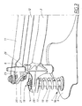
- Figure 3 shows an isometric view of the impact absorbing means 13 in a first position when it is not deflected and Figure 4 shows the impact absorbing means 13 in a second position when it is deflected.
- At least one of the attachment means 7 is provided with impact absorbing means 13, which is arranged to dampen an impact force F acting on at least one wiper shaft during a collision with an object.
- the impact absorbing means 13 is arranged to give way and to allow deflection of the arm structure 2 and its first wiper shaft 8, when subjected to an impact force F, as shown in Fig. 4 .
- the arm structure 2 gives way from a first position, shown in Figure 1 and 3 , to a second position, shown in Figure 2 and 4 .
- the impact absorbing means 13 is also arranged to return the arm structure 2 and its first wiper shaft 8 from the second position to the first position after the action of the impact force F so that the wiper assembly 1 can be reused.
- the impact absorbing means 13 shown in Figure 3 and 4 is positioned below a first wiper shaft 8, as shown in Figure 1 and 2 .
- the arm structure 2 is provided with the first wiper shaft 8, which is connected to the first and second elongated arms 11, 12 via the second and third connectors 20, 21.
- the arm structure 2 is provided with an opening 14 in a protruding part 28 arranged on the arm structure 2.
- the impact absorbing means 13 is arranged on a guide pin 15, which has a first end 16 fixedly attached to the vehicle chassis 5 and a free second end 17. At least one end of the arm structure 2 is movable guided on the guide pin 15.
- the guide pin 15 is provided with a stop 18 at the second end 17 of the guide pin 15, which stop 18 is arranged to constitute a terminal point for a deflection movement when the arm structure 2 and its first wiper shaft 8 moves between the first and the second position or vice versa or when the arm structure 2 and its first wiper shaft 8 is stationary in its first position.
- the stop 18 is constituted by a washer and a nut.
- the impact absorbing means 13 is a resilient means, which can be a coil spring as shown in Figure 3 .
- the magnitude of the impact force F, that is needed to compress the coil spring and deflect the arm structure 2 between the first and second positions, can easily be adapted to a desired condition by providing a spring having a different size and/or spring constant.
Landscapes
- Engineering & Computer Science (AREA)
- Mechanical Engineering (AREA)
- Vibration Dampers (AREA)
Abstract
Description
- The present invention relates generally to a pedestrian safety device, and more particularly, to a wiper assembly which is designed to dampen an impact force for an extraneous object during a collision.
- The present invention relates to a wiper assembly according to claim 1 and further to a vehicle comprising a wiper assembly according to
claim 7. - Vehicles are equipped with windscreen wipers to wipe rain, snow, dirt etc. off from the windshield. The windscreen wipers are generally arranged on a wiper assembly which is fixedly mounted onto the vehicle chassis. The wiper assembly is in most cases arranged below the bonnet, with exception to the windshield wipers which protrude upwards in a space between the windshield and a rear edge of the bonnet. The windshield wipers are mounted on wiper shafts which have a fixed length in their longitudinal direction and protrude upwards from the wiper assembly. During a collision with for example a pedestrian, the pedestrian will in a worst case scenario end up on top of the bonnet which will give way and be deformed to dampen the fall. Even if the bonnet gives way during a collision the protruding parts such as the wiper shafts which are fixedly mounted below the bonnet will still protrude upwards. When the bonnet gives way and deforms, the protruding parts will still constitute hard impact objects which the pedestrian may contact during collision and which objects may injure the pedestrian when landing on the bonnet.
- Thus it is an object to minimize the magnitude of impact forces caused by protruding objects, to which the pedestrian can be exposed. There are prior art arrangements which have tried to address this problem. For example,
WO 2007/020175 shows a known windshield wiper device which comprises a collapsible wiper arm spindle, which spindle can be displaced axially when subjected to an impact. The spindle is fitted with a radial spring loaded device holding the spindle in position. When the spindle is subjected to an axial force exceeding the radial spring force, the spindle is displaced. However, a great impact force is required to displace the spindle. When the spindle gives way for the impact force it will happen suddenly and the spindle will immediately touch the bottom of the windshield wiper device and thus not dampen the blow from the impact force. Another disadvantage with this windshield wiper device is that when it once has been subjected to an impact, the device will have to be exchanged since it will not be able to remain functional. - One object of the present invention is to provide an improved wiper assembly that addresses the above problems with wiper assemblies, and it is also an object of the present invention to provide a wiper assembly which is impact absorbing and can remain functional after an impact.
- The above problems have been solved by a wiper assembly according to the appended claims.
- According to a preferred embodiment, the invention relates to a wiper assembly for a vehicle, which wiper assembly comprises an arm structure which is mounted to said vehicle with attachment means and which arm structure is provided with protruding wiper shafts. Said wiper shafts are rotatable and mounted on said arm structure, and an electric motor is arranged to generate and transfer rotational movement to said wiper shafts via a linkage.
- According to an example at least one of the attachment means is provided with impact absorbing means, which is arranged to dampen an impact force acting on at least one wiper shaft during a collision with an object.
- According to an example said impact absorbing means is arranged to give way from a first position to a second position when said wiper shaft and said arm structure are subjected to an impact force and to return said wiper shaft and said arm structure to said first position after being subjected to an impact.
- According to an example said impact absorbing means is arranged on a guide pin, which has a first end fixedly attached to said vehicle and a free second end, and that at least one end of said arm structure is movable guided on the guide pin.
- According to an example said guide pin is provided with a stop at said second end, which stop constitutes a terminal point for a deflection movement between said second and first positions of said wiper shaft and said arm structure when provided in said first position.
- According to an example said impact absorbing means is a resilient means. According to another example said resilient means is a coil spring.
- According to another example attachment means with impact absorbing means can be provided in both ends of the arm structure below the wiper shafts.
- The invention will be described in detail with reference to the attached figures. It is to be understood that the drawings are designed solely for the purpose of illustration and are not intended as a definition of the limits of the invention, for which reference should be made to the appended claims. It should be further understood that the drawings are not necessarily drawn to scale and that, unless otherwise indicated, they are merely intended to schematically illustrate the structures and procedures described herein.
- Figure 1
- shows an isometric view of a wiper assembly in a first position when it is not deflected according to one embodiment of the invention;
- Figure 2
- shows an isometric view of a wiper assembly in a second position when it is deflected;
- Figure 3
- shows an isometric view, mirror-inverted in relation to
Figure 1 , of the impact absorbing means in a first position when it is not deflected; and - Figure 4
- shows an isometric view, mirror-inverted in relation to
Figure 2 , of the impact absorbing means in a second position when it is deflected. - In the description directions, such as upwards, downwards etc., will be given, which are to be interpreted in relation to the longitudinal axis of a vehicle in a forward driving condition.
- In a preferred embodiment the major part of the wiper assembly according to the invention is mounted below a bonnet of the vehicle, except for windshield wipers which protrude upwards towards a windshield in a free space between the windshield and the bonnet.
-
Figure 1 shows an isometric view of a wiper assembly 1 in a first position when it is not deflected andFigure 2 shows the wiper assembly in a second position when it is deflected. The first position is a normal operating position for the wiper assembly 1 and the second position is the position during an impact event for the wiper assembly 1. The wiper assembly 1 comprises anarm structure 2 which includes ahousing 3, wherein an electric motor 4 is mounted. Thehousing 3 is preferably fixedly attached to thevehicle chassis 5 withrubber bushings 6, which rubber bushings 6 absorb vibrations and mitigate noise created from its mounting. - The
arm structure 2 is mounted to thevehicle chassis 5 with attachment means 7 and whicharm structure 2 is provided with upwards protrudingwiper shafts arm structure 2. The electric motor 4 is arranged to generate and transfer rotational movement to thewiper shafts wiper shafts wiper shafts - The rotational movement from the motor 4 is transferred to the
wiper shafts linkage 10. The linkage comprises at least twoelongated arms wiper shafts connectors first connector 19 with a first end is connected to anoutput shaft 23 of the motor 4 and a second end of thefirst connector 19 is connected to afirst end 24 of the firstelongated arm 11. Asecond end 25 of the firstelongated arm 11 is connected to a first end of asecond connector 20, which in its second end is connected to thefirst wiper shaft 8. - The
first wiper shaft 8 is connected to a first end of athird connector 21, whichthird connector 21 in a second end is connected to afirst end 26 of a secondelongated arm 12. Asecond end 27 of the secondelongated arm 12 is connected to a first end of afourth connector 22, which in its second end is connected to asecond wiper shaft 9. - In operation, the motor 4 drives the
first connector 19 which drives the motor 4 via the firstelongated arm 11 and thesecond connector 20. Thus, thefirst connector 19, the firstelongated arm 11 and thesecond connector 20 transfers the rotational movement from the motor 4 to thefirst wiper shaft 8. - Thus, the
first wiper shaft 8, drives thethird connector 21, which in turn drives and transfers the rotational movement from thefirst wiper shaft 8 to thesecond wiper shaft 9 via the secondelongated arm 12 and thefourth connector 22. In operation, the first and second wiper shafts 8, 9 rotates synchronous with each other. -
Figure 3 shows an isometric view of theimpact absorbing means 13 in a first position when it is not deflected andFigure 4 shows theimpact absorbing means 13 in a second position when it is deflected. - At least one of the attachment means 7 is provided with
impact absorbing means 13, which is arranged to dampen an impact force F acting on at least one wiper shaft during a collision with an object. Theimpact absorbing means 13 is arranged to give way and to allow deflection of thearm structure 2 and itsfirst wiper shaft 8, when subjected to an impact force F, as shown inFig. 4 . Thus, when subjected to an impact, thearm structure 2 gives way from a first position, shown inFigure 1 and3 , to a second position, shown inFigure 2 and4 . Theimpact absorbing means 13 is also arranged to return thearm structure 2 and itsfirst wiper shaft 8 from the second position to the first position after the action of the impact force F so that the wiper assembly 1 can be reused. - The impact absorbing means 13 shown in
Figure 3 and4 is positioned below afirst wiper shaft 8, as shown inFigure 1 and 2 . Thearm structure 2 is provided with thefirst wiper shaft 8, which is connected to the first and secondelongated arms third connectors arm structure 2 is provided with anopening 14 in a protrudingpart 28 arranged on thearm structure 2. Theimpact absorbing means 13 is arranged on aguide pin 15, which has afirst end 16 fixedly attached to thevehicle chassis 5 and a freesecond end 17. At least one end of thearm structure 2 is movable guided on theguide pin 15. - The
guide pin 15 is provided with astop 18 at thesecond end 17 of theguide pin 15, which stop 18 is arranged to constitute a terminal point for a deflection movement when thearm structure 2 and itsfirst wiper shaft 8 moves between the first and the second position or vice versa or when thearm structure 2 and itsfirst wiper shaft 8 is stationary in its first position. In one embodiment thestop 18 is constituted by a washer and a nut. - The
impact absorbing means 13 is a resilient means, which can be a coil spring as shown inFigure 3 . The magnitude of the impact force F, that is needed to compress the coil spring and deflect thearm structure 2 between the first and second positions, can easily be adapted to a desired condition by providing a spring having a different size and/or spring constant. - The invention is not limited to the above examples, but may be varied freely within the scope of the appended claims.
Claims (7)
- Wiper assembly for a vehicle, which wiper assembly comprises- an arm structure (2) which is mounted to said vehicle with attachment means (7) and which arm structure (2) is provided with protruding wiper shafts (8, 9),- said wiper shafts (8, 9) are rotatable and mounted on said arm structure (2),- an electric motor (4) is arranged to generate and transfer rotational movement to said wiper shafts (8, 9) via a linkage (10),characterized in that- at least one of the attachment means (7) is provided with impact absorbing means (13), which is arranged to dampen an impact force F acting on at least one wiper shaft (8, 9) during a collision with an object.
- Wiper assembly according to claim 1, characterized in that said impact absorbing means (13) is arranged to give way from a first position to a second position when said wiper shaft (8, 9) and said arm structure (2) are subjected to an impact force F and to return said wiper shaft (8, 9) and said arm structure (2) to said first position after subjected to an impact.
- Wiper assembly according to claim 1 or 2, characterized in that said impact absorbing means (13) is arranged on a guide pin (15), which has a first end (16) fixedly attached to said vehicle and a free second end (17), and that at least one end of said arm structure (2) is movable guided on the guide pin (15).
- Wiper assembly according to claim 3, characterized in that said guide pin (15) is provided with a stop (18) at said second end (17), which stop (18) constitutes a terminal point for a deflection movement between said second and first positions of said wiper shaft (8, 9) and said arm structure (2) when provided in said first position.
- Wiper assembly according to any of claims 1-3, characterized in that said impact absorbing means (13) is a resilient means.
- Wiper assembly according to claim 5, characterized in that said resilient means is a coil spring.
- A vehicle comprising a wiper assembly according to claims 1-6.
Priority Applications (2)
| Application Number | Priority Date | Filing Date | Title |
|---|---|---|---|
| EP20080159837 EP2143601B1 (en) | 2008-07-07 | 2008-07-07 | Wiper assembly |
| CN2009201567004U CN201511932U (en) | 2008-07-07 | 2009-06-23 | Wiper assembly and vehicles including the wiper assembly |
Applications Claiming Priority (1)
| Application Number | Priority Date | Filing Date | Title |
|---|---|---|---|
| EP20080159837 EP2143601B1 (en) | 2008-07-07 | 2008-07-07 | Wiper assembly |
Publications (2)
| Publication Number | Publication Date |
|---|---|
| EP2143601A1 true EP2143601A1 (en) | 2010-01-13 |
| EP2143601B1 EP2143601B1 (en) | 2013-01-23 |
Family
ID=39929752
Family Applications (1)
| Application Number | Title | Priority Date | Filing Date |
|---|---|---|---|
| EP20080159837 Not-in-force EP2143601B1 (en) | 2008-07-07 | 2008-07-07 | Wiper assembly |
Country Status (2)
| Country | Link |
|---|---|
| EP (1) | EP2143601B1 (en) |
| CN (1) | CN201511932U (en) |
Cited By (3)
| Publication number | Priority date | Publication date | Assignee | Title |
|---|---|---|---|---|
| FR2965773A1 (en) * | 2010-10-11 | 2012-04-13 | Peugeot Citroen Automobiles Sa | Flexible fitting for outlet axle of windscreen wiper mechanism of motor vehicle for protecting pedestrians during shock, has ball-joint link including ball-joint fixed at pressure spring located in housing placed in outlet axle |
| DE102016206778A1 (en) * | 2016-04-21 | 2017-10-26 | Robert Bosch Gmbh | Windscreen wiper device and motor vehicle with such a windscreen wiper device |
| CN108819901A (en) * | 2018-06-14 | 2018-11-16 | 贵州大学 | A kind of automobile wiper support device being easily installed |
Families Citing this family (1)
| Publication number | Priority date | Publication date | Assignee | Title |
|---|---|---|---|---|
| CN103847699B (en) * | 2012-12-03 | 2016-12-21 | 博世汽车部件(长沙)有限公司 | Wiper system and toggle thereof for vehicle |
Citations (7)
| Publication number | Priority date | Publication date | Assignee | Title |
|---|---|---|---|---|
| WO2003047926A1 (en) * | 2001-12-07 | 2003-06-12 | Valeo Systemes D'essuyage | Arrangement for fixing a wiper device which can be used to retract the drive shaft in the event of an impact |
| DE10255774A1 (en) * | 2002-11-29 | 2004-06-09 | Robert Bosch Gmbh | Windscreen wiper device, in particular for a motor vehicle |
| DE10255775A1 (en) * | 2002-11-29 | 2004-06-09 | Robert Bosch Gmbh | Windscreen wiper device, in particular for a motor vehicle |
| US20040123412A1 (en) * | 2002-12-30 | 2004-07-01 | Buchanan Harry Charles | Energy absorbing pedestrian safety feature for vehicle wiper pivot apparatus |
| FR2859961A1 (en) * | 2003-09-19 | 2005-03-25 | Volkswagen Ag | Flexible assembly for driving shaft of windshield wiper, has bushings displaced, along with shaft, in axial direction when shaft is subjected to collision, and clutch spring arranged coaxially to shaft |
| WO2007020175A1 (en) | 2005-08-18 | 2007-02-22 | Robert Bosch Gmbh | Windshield wiper device |
| DE102005039763A1 (en) * | 2005-08-23 | 2007-03-01 | Robert Bosch Gmbh | Windshield wiper device |
-
2008
- 2008-07-07 EP EP20080159837 patent/EP2143601B1/en not_active Not-in-force
-
2009
- 2009-06-23 CN CN2009201567004U patent/CN201511932U/en not_active Expired - Lifetime
Patent Citations (7)
| Publication number | Priority date | Publication date | Assignee | Title |
|---|---|---|---|---|
| WO2003047926A1 (en) * | 2001-12-07 | 2003-06-12 | Valeo Systemes D'essuyage | Arrangement for fixing a wiper device which can be used to retract the drive shaft in the event of an impact |
| DE10255774A1 (en) * | 2002-11-29 | 2004-06-09 | Robert Bosch Gmbh | Windscreen wiper device, in particular for a motor vehicle |
| DE10255775A1 (en) * | 2002-11-29 | 2004-06-09 | Robert Bosch Gmbh | Windscreen wiper device, in particular for a motor vehicle |
| US20040123412A1 (en) * | 2002-12-30 | 2004-07-01 | Buchanan Harry Charles | Energy absorbing pedestrian safety feature for vehicle wiper pivot apparatus |
| FR2859961A1 (en) * | 2003-09-19 | 2005-03-25 | Volkswagen Ag | Flexible assembly for driving shaft of windshield wiper, has bushings displaced, along with shaft, in axial direction when shaft is subjected to collision, and clutch spring arranged coaxially to shaft |
| WO2007020175A1 (en) | 2005-08-18 | 2007-02-22 | Robert Bosch Gmbh | Windshield wiper device |
| DE102005039763A1 (en) * | 2005-08-23 | 2007-03-01 | Robert Bosch Gmbh | Windshield wiper device |
Cited By (3)
| Publication number | Priority date | Publication date | Assignee | Title |
|---|---|---|---|---|
| FR2965773A1 (en) * | 2010-10-11 | 2012-04-13 | Peugeot Citroen Automobiles Sa | Flexible fitting for outlet axle of windscreen wiper mechanism of motor vehicle for protecting pedestrians during shock, has ball-joint link including ball-joint fixed at pressure spring located in housing placed in outlet axle |
| DE102016206778A1 (en) * | 2016-04-21 | 2017-10-26 | Robert Bosch Gmbh | Windscreen wiper device and motor vehicle with such a windscreen wiper device |
| CN108819901A (en) * | 2018-06-14 | 2018-11-16 | 贵州大学 | A kind of automobile wiper support device being easily installed |
Also Published As
| Publication number | Publication date |
|---|---|
| CN201511932U (en) | 2010-06-23 |
| EP2143601B1 (en) | 2013-01-23 |
Similar Documents
| Publication | Publication Date | Title |
|---|---|---|
| US7823246B2 (en) | Breakaway mounting bracket assembly for a wiper system | |
| EP2143601B1 (en) | Wiper assembly | |
| KR20010005814A (en) | Wiper system | |
| CN102582567A (en) | Engine hood pop-up device beneficial to pedestrian protection | |
| CN100537311C (en) | Windshield wiping device, especially for a motor vehicle | |
| KR100824550B1 (en) | Wiper arm | |
| US8510896B2 (en) | Wiper device for vehicle | |
| US20070289081A1 (en) | Windscreen Wiper Device | |
| JP4950925B2 (en) | Wiper device | |
| US8516647B2 (en) | Collapsible pivot body for a windshield wiper system | |
| US7240392B2 (en) | Park safe mechanism for wiper systems | |
| EP3388293B1 (en) | Movement transmission device for vehicle wiper device | |
| JP4199696B2 (en) | Wiper device | |
| EP3395628A1 (en) | Vehicle wiper device | |
| KR20020038122A (en) | Safety device for pivot shaft of windshield wiper | |
| KR20060109992A (en) | Device for fastening a window wiping device to a motor vehicle | |
| JP3205293B2 (en) | Wiper bracket | |
| KR100980968B1 (en) | Wiper device for Vehicle | |
| EP2974914B1 (en) | Bearing preventing overloading, especially in the windshield wiper mechanism of automobiles, and automobile windshield wiping mechanism containing such a bearing | |
| KR100326716B1 (en) | Impulse absorption apparatus of pivot axis for wiper arm of car | |
| KR100521679B1 (en) | Wind shield wiper driving mechanism for automobile | |
| KR200303896Y1 (en) | Wiper device for vehicle | |
| KR0158998B1 (en) | Wiper for a vehicle | |
| KR100368925B1 (en) | Wiper device for use in an automobile | |
| KR20150110274A (en) | Wiper motor apparatus provided with shock absorbing structure for pedestrian protection |
Legal Events
| Date | Code | Title | Description |
|---|---|---|---|
| PUAI | Public reference made under article 153(3) epc to a published international application that has entered the european phase |
Free format text: ORIGINAL CODE: 0009012 |
|
| AK | Designated contracting states |
Kind code of ref document: A1 Designated state(s): AT BE BG CH CY CZ DE DK EE ES FI FR GB GR HR HU IE IS IT LI LT LU LV MC MT NL NO PL PT RO SE SI SK TR |
|
| AX | Request for extension of the european patent |
Extension state: AL BA MK RS |
|
| 17P | Request for examination filed |
Effective date: 20100512 |
|
| AKX | Designation fees paid |
Designated state(s): DE GB SE |
|
| 17Q | First examination report despatched |
Effective date: 20110404 |
|
| RAP1 | Party data changed (applicant data changed or rights of an application transferred) |
Owner name: VOLVO CAR CORPORATION |
|
| GRAP | Despatch of communication of intention to grant a patent |
Free format text: ORIGINAL CODE: EPIDOSNIGR1 |
|
| GRAS | Grant fee paid |
Free format text: ORIGINAL CODE: EPIDOSNIGR3 |
|
| GRAA | (expected) grant |
Free format text: ORIGINAL CODE: 0009210 |
|
| AK | Designated contracting states |
Kind code of ref document: B1 Designated state(s): DE GB SE |
|
| REG | Reference to a national code |
Ref country code: GB Ref legal event code: FG4D |
|
| REG | Reference to a national code |
Ref country code: DE Ref legal event code: R096 Ref document number: 602008021825 Country of ref document: DE Effective date: 20130321 |
|
| REG | Reference to a national code |
Ref country code: SE Ref legal event code: TRGR |
|
| PLBE | No opposition filed within time limit |
Free format text: ORIGINAL CODE: 0009261 |
|
| STAA | Information on the status of an ep patent application or granted ep patent |
Free format text: STATUS: NO OPPOSITION FILED WITHIN TIME LIMIT |
|
| 26N | No opposition filed |
Effective date: 20131024 |
|
| REG | Reference to a national code |
Ref country code: DE Ref legal event code: R097 Ref document number: 602008021825 Country of ref document: DE Effective date: 20131024 |
|
| PGFP | Annual fee paid to national office [announced via postgrant information from national office to epo] |
Ref country code: SE Payment date: 20190709 Year of fee payment: 12 |
|
| PGFP | Annual fee paid to national office [announced via postgrant information from national office to epo] |
Ref country code: GB Payment date: 20190710 Year of fee payment: 12 |
|
| REG | Reference to a national code |
Ref country code: SE Ref legal event code: EUG |
|
| GBPC | Gb: european patent ceased through non-payment of renewal fee |
Effective date: 20200707 |
|
| PG25 | Lapsed in a contracting state [announced via postgrant information from national office to epo] |
Ref country code: GB Free format text: LAPSE BECAUSE OF NON-PAYMENT OF DUE FEES Effective date: 20200707 |
|
| PG25 | Lapsed in a contracting state [announced via postgrant information from national office to epo] |
Ref country code: SE Free format text: LAPSE BECAUSE OF NON-PAYMENT OF DUE FEES Effective date: 20200708 |
|
| PGFP | Annual fee paid to national office [announced via postgrant information from national office to epo] |
Ref country code: DE Payment date: 20230620 Year of fee payment: 16 |
|
| P01 | Opt-out of the competence of the unified patent court (upc) registered |
Effective date: 20231212 |
|
| REG | Reference to a national code |
Ref country code: DE Ref legal event code: R119 Ref document number: 602008021825 Country of ref document: DE |
|
| PG25 | Lapsed in a contracting state [announced via postgrant information from national office to epo] |
Ref country code: DE Free format text: LAPSE BECAUSE OF NON-PAYMENT OF DUE FEES Effective date: 20250201 |