EP2142853B1 - Ceramic burner - Google Patents
Ceramic burner Download PDFInfo
- Publication number
- EP2142853B1 EP2142853B1 EP08749938.0A EP08749938A EP2142853B1 EP 2142853 B1 EP2142853 B1 EP 2142853B1 EP 08749938 A EP08749938 A EP 08749938A EP 2142853 B1 EP2142853 B1 EP 2142853B1
- Authority
- EP
- European Patent Office
- Prior art keywords
- fuel
- chamber
- air
- ceramic burner
- burner according
- Prior art date
- Legal status (The legal status is an assumption and is not a legal conclusion. Google has not performed a legal analysis and makes no representation as to the accuracy of the status listed.)
- Active
Links
Images

Classifications
-
- C—CHEMISTRY; METALLURGY
- C21—METALLURGY OF IRON
- C21B—MANUFACTURE OF IRON OR STEEL
- C21B9/00—Stoves for heating the blast in blast furnaces
-
- F—MECHANICAL ENGINEERING; LIGHTING; HEATING; WEAPONS; BLASTING
- F23—COMBUSTION APPARATUS; COMBUSTION PROCESSES
- F23D—BURNERS
- F23D14/00—Burners for combustion of a gas, e.g. of a gas stored under pressure as a liquid
- F23D14/20—Non-premix gas burners, i.e. in which gaseous fuel is mixed with combustion air on arrival at the combustion zone
- F23D14/22—Non-premix gas burners, i.e. in which gaseous fuel is mixed with combustion air on arrival at the combustion zone with separate air and gas feed ducts, e.g. with ducts running parallel or crossing each other
-
- C—CHEMISTRY; METALLURGY
- C21—METALLURGY OF IRON
- C21B—MANUFACTURE OF IRON OR STEEL
- C21B9/00—Stoves for heating the blast in blast furnaces
- C21B9/02—Brick hot-blast stoves
- C21B9/04—Brick hot-blast stoves with combustion shaft
-
- C—CHEMISTRY; METALLURGY
- C21—METALLURGY OF IRON
- C21B—MANUFACTURE OF IRON OR STEEL
- C21B9/00—Stoves for heating the blast in blast furnaces
- C21B9/02—Brick hot-blast stoves
- C21B9/06—Linings
-
- F—MECHANICAL ENGINEERING; LIGHTING; HEATING; WEAPONS; BLASTING
- F27—FURNACES; KILNS; OVENS; RETORTS
- F27D—DETAILS OR ACCESSORIES OF FURNACES, KILNS, OVENS OR RETORTS, IN SO FAR AS THEY ARE OF KINDS OCCURRING IN MORE THAN ONE KIND OF FURNACE
- F27D99/00—Subject matter not provided for in other groups of this subclass
- F27D99/0001—Heating elements or systems
- F27D99/0033—Heating elements or systems using burners
-
- Y—GENERAL TAGGING OF NEW TECHNOLOGICAL DEVELOPMENTS; GENERAL TAGGING OF CROSS-SECTIONAL TECHNOLOGIES SPANNING OVER SEVERAL SECTIONS OF THE IPC; TECHNICAL SUBJECTS COVERED BY FORMER USPC CROSS-REFERENCE ART COLLECTIONS [XRACs] AND DIGESTS
- Y02—TECHNOLOGIES OR APPLICATIONS FOR MITIGATION OR ADAPTATION AGAINST CLIMATE CHANGE
- Y02E—REDUCTION OF GREENHOUSE GAS [GHG] EMISSIONS, RELATED TO ENERGY GENERATION, TRANSMISSION OR DISTRIBUTION
- Y02E20/00—Combustion technologies with mitigation potential
- Y02E20/34—Indirect CO2mitigation, i.e. by acting on non CO2directly related matters of the process, e.g. pre-heating or heat recovery
Definitions
- the present invention relates to a ceramic burner for use in a combustion chamber of a regenerative heat generator, such as a hot blast stove of a blast furnace.
- Such stoves generally comprise a combustion chamber and a heat-retention shaft.
- the combustion chamber and the heat-retention shaft are separated from one another by a wall constructed from refractory bricks.
- a ceramic burner such a ceramic burner is located in a bottom section of the combustion chamber.
- Combustion air and combustible fuel are supplied to the ceramic burner and a mixture of the combustion air and fuel is burned in the combustion chamber.
- the flue gases emanating from the combustion rise upwards in the combustion chamber, are diverted via a cupola and then pass through the heat-retention shaft filled with checker bricks. Heat from the flue gases is absorbed by the checker bricks.
- the flue gasses which have now cooled down escape the stove via an exhaust gas chamber and at least one discharge port.
- the supply of combustion air and fuel is discontinued and air is blown through the stove in the opposite direction.
- the air is heated as it passes through the heat-retention shaft containing the hot checker bricks, diverted via a cupola into the combustion chamber, where it leaves the stove via a hot blast outlet in the shell of the stove to be fed to the blast furnace.
- the ceramic burner generally comprises a fuel chamber for feeding the combustible fuel supplied to the ceramic burner to a mixing region and an air chamber for feeding the combustion air supplied to the ceramic burner to the mixing region.
- the fuel and air chambers are usually separated from each other by means of a partition constructed from refractory bricks.
- the combustible fuel and the combustion air are mixed in the mixing region to form a combustible mixture.
- Another problem is the combustible fuel, e.g. CO gas, leaking out of the fuel chamber and causing a high concentration of CO in the exhaust gasses.
- This problem is particularly present in stoves where the burner feed chamber and the exhaust gas chamber are arranged next to each other in the bottom section of the stove, with only a separation of refractory bricks between them. Due to the porosity of the refractory bricks, such a separation of refractory bricks can never be fully gastight. Leakage of fuel out of the fuel chamber, e.g. into the exhaust gas chamber, is accentuated by the ageing brick walls. The leakage of CO gas into the exhaust gas chamber and hence into the exhaust fumes causes the CO concentration to be too high.
- CO gas e.g. CO gas
- a crossover from the fuel chamber into the air chamber, and vice versa, may cause uncontrolled damage to the refractory design and accelerate the destruction of the refractory bricks.
- US 4,997,362 discloses a gas tight metallic fuel container arranged in the burner feed chamber, the fuel container comprising the fuel chamber therein, a wall portion of the fuel container forming the partition wall between the fuel chamber and the air chamber, thereby avoiding a crossover from the fuel chamber into the air chamber, and vice versa.
- the object of the present invention is to provide an improved ceramic burner for use in a combustion chamber of a regenerative heat generator, such as a hot blast stove. This object is achieved by a ceramic burner as claimed in claim 1.
- the present invention proposes a ceramic burner for use in a combustion chamber of a regenerative heat generator, such as a hot blast stove of a blast furnace, wherein the ceramic burner comprises a burner feed chamber with a partition wall for dividing the burner feed chamber into a fuel chamber and an air chamber.
- the fuel chamber has a fuel inlet for receiving combustible fuel and a fuel outlet for feeding the combustible fuel to a mixing zone.
- the air chamber has an air inlet for receiving combustion air and an air outlet for feeding the combustion air to the mixing zone.
- the ceramic burner further comprises a gastight metallic fuel container arranged in the burner feed chamber, the fuel container comprising the fuel chamber therein, a wall portion of the fuel container forming the partition wall between the fuel chamber and the air chamber.
- the gastight metallic fuel container effectively prevents that the contents of fuel chamber leaks into the air chamber, thereby avoiding a premature mixing thereof. Also, the metallic fuel container is only insignificantly influenced by the ageing of the installation. The metallic partition wall does not deteriorate in such as way as to allow fuel to pass therethrough.
- the ceramic burner according to the present invention and the regenerative heat generator comprising such a ceramic burner therefore have a prolonged life.
- the gastight metallic fuel container allows for the fuel chamber to be effectively isolated from the air chamber within the burner feed chamber and from the exhaust gas chamber.
- the burner feed chamber is divided into fuel and air chambers, simply by installing the fuel container therein.
- the fuel chamber is defined as being the space inside the fuel container and the air chamber is defined as being the space outside the fuel container.
- the gastight metallic fuel container prevents any leakages of combustible fuel, such as CO rich gas, from the fuel chamber into the exhaust gas chamber. The CO content of the exhaust fumes is thereby not unnecessarily high.
- the partition wall is undulated in a direction perpendicular to the fuel flow towards the mixing zone.
- the undulated partition wall preferably forms fuel channels inside the fuel container and air channels outside the fuel container, the alternating fuel channels and air channels leading the combustible fuel and the combustion air to the mixing zone.
- the undulated configuration of the partition wall allows for the fuel and air to reach into the respective other chamber, while still avoiding their mixing.
- the fuel and the air are guided towards the mixing zone in alternate fuel and air channels opening up into the mixing zone.
- the fuel and air are already premixed on entry into the mixing zone. This provides for an improved mixing of the fuel and the air in the mixing zone and hence for a better combustible mixture.
- the fuel container is suspended from a metallic construction resting on a support rim of the combustion chamber.
- a suspended arrangement of the fuel container in the burner feed chamber allows to prolong the lifetime of the fuel container and hence of the ceramic burner. Indeed, as the fuel container is exposed to expansion and/or compression effects with respect to the burner feed chamber, the fuel container itself is free to expand or contract within the burner feed chamber, without being exposed to expansion and compression forces with respect to the burner feed chamber.
- the metallic construction can comprise a plurality of metal bars, which may have a double T shaped cross-section.
- the support rim comprises a plurality of metal support plates in the refractory brickwork of the combustion chamber for supporting the metallic construction.
- the metal support plates can be arranged so as to be moveably resting on the refractory brickwork of the combustion chamber.
- the metal support plates are arranged in an interlocked configuration so as to resist tensile stress.
- the metal support plates can be bolted together.
- the fuel container can be screwed to the metallic construction. This allows for the fuel container to be easily detached for maintenance or replacement if needed. It should however be noted that it is not excluded to connect the fuel container to the metallic construction in a more permanent manner, e.g. through welding.
- the fuel container comprises a plurality of metal sheet elements, which are preferably screwed together to form the fuel container.
- the fuel container can hence be constructed on site. Furthermore, the access to the burner feed chamber need not be as big as to fit the completed fuel container through. The access can be kept relatively small. Another advantage of such a construction is the fact that, should a portion of the fuel container be damaged, that portion can easily be detached for maintenance or replacement, without having to dismantle the whole ceramic burner.
- the metallic construction and/or the fuel container and/or an inlet duct of the fuel container are made from stainless steel.
- the ceramic burner may, in addition to the fuel container, comprise a metallic air container, the air container comprising the air chamber therein.
- the air container is not described in detail herein, it will be understood that it may comprise the same features as the fuel container, in particular concerning its construction and attachment within the burner feed chamber.
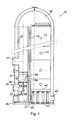
- Fig.1 shows a cut through a typical hot blast stove 10, comprising a combustion chamber 12 and a heat-retention chamber 14 separated from one another by a wall 16 constructed from refractory bricks.
- a ceramic burner 20 is located in a bottom section 18 of the combustion chamber 12.
- the ceramic burner 20 comprises a burner feed chamber 21 with a fuel inlet 22 for feeding combustible fuel, generally gas, to a fuel chamber 24 of the burner feed chamber 21 and an air inlet 26 for feeding combustion air to an air chamber 28 of the burner feed chamber 21.
- the fuel and air chambers 24, 28 are separated from each other by means of a partition wall 30.
- the fuel chamber 24 has a fuel outlet 32 opening up into a mixing zone 34.
- the air chamber 28 has an air outlet 36 also opening up into the mixing zone 34. In the mixing zone 34, the combustible fuel and the combustion air are mixed to form a combustible mixture, which is then burnt in the combustion chamber 12 of the hot blast stove 10.
- combustible fuel and combustion air are fed to the ceramic burner 20 and the resulting combustible mixture is lit.
- the flue gases emanating from the combustion of the combustible mixture rise upwards in the combustion chamber 12, At the upper end of the combustion chamber 12, the hot flue gases enter a cupola 38 which diverts them into the heat-retention chamber 14 filled with checker bricks, schematically represented by reference sign 40.
- the checker bricks 40 absorb heat from the flue gases.
- the checker bricks 40 are maintained in the heat-retention chamber 14 above an exhaust gas chamber 41 by means of a checker grid 42.
- the flue gasses, which have now cooled down escape the stove 10 via the exhaust gas chamber 41 through a discharge port 43.
- the supply of combustion air and fuel is discontinued and air is blown through the stove 10 in the opposite direction.
- This air is heated as it passes through the heat-retention chamber 14 containing the hot checker bricks 40.
- the heated air is then fed via the cupola 38 into the combustion chamber 12.
- the hot air finally leaves the combustion chamber 12 via a hot blast outlet 44 to be fed into a blast furnace (not shown).
- the ceramic burner 20 comprises a gastight metallic fuel container 48, which is arranged in the burner feed chamber 21.
- a wall portion of the fuel container 48 forms the partition wall 30.
- the partition wall 30, which is metallic, forms a gastight barrier between the fuel and air chambers 24, 28, thereby preventing any gas from leaking from the fuel chamber 24 into the air chamber 28.
- the gastight metallic fuel container 48 also avoids that gas can leak from the gas chamber 24 to the exhaust gas chamber 41 through the refractory brick wall 16.
- the fuel container 48 can be more closely described by referring to figures 2 and 3 .
- the fuel container 48 comprises a base portion 52, a first wall portion 54 conforming to the side wall of the burner feed chamber 21, a second wall portion 56 forming the partition wall 30 and a top portion 58, the fuel chamber 24 being arranged in the fuel container 48.
- a first opening 60 is arranged in the first wall portion 54 for connecting to the fuel inlet 22.
- the top portion 58 comprises a second opening 62 for feeding fuel from the fuel container 48 to the mixing zone 34.
- the second wall portion 56 is undulated such that, in the region of the second wall portion 56, alternate channels of air and fuel are led to the mixing zone 34. This provides good mixing conditions for the air and the fuel.
- the second wall portion 56 is constructed from a plurality of metal sheet elements 64 which are connected together.
- the first wall portion 54 and the base portion 52 are preferably also constructed from such metal sheet elements 64.
- Such a construction, wherein the individual metal sheet elements 64 are connected together e.g. by means of screws, allows for the fuel container 48 to be assembled on-site within the burner feed chamber 21.
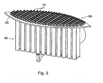
- FIG.3 A further important aspect of the present invention can be illustrated by referring to Fig.3 and concerns the connection of the fuel container 48 in the burner feed chamber 21.
- the burner feed chamber 21 is provided with a support rim (not shown) on which rests a metallic construction 66.
- the metallic construction 66 serves as support structure for the fuel container 48.
- the top portion 58 of the fuel container 48 is connected to the metallic construction 66 in such a way that the fuel container 48 is suspended from the metallic construction 66.
- the suspended arrangement of the fuel container 48 in the burner feed chamber 21 protects the latter from any expansion or compression forces due to the temperature difference. The life of the ceramic burner 20 is thereby prolonged.
- the metallic construction 66 comprises metallic support plates 68 resting on the support rim and a plurality of metal bars 70 arranged in parallel and resting on the metallic support plates 68.
- the metal bars 70 may, as shown in Fig.3 , have a double T-shaped cross-section.
- the fuel container 48 can be connected to the metallic construction 66 by means of screws. The fuel and air coming from the fuel and air chambers 24, 28 pass between the metal bars 70 to reach the mixing zone 34.
- the fuel container 48 and the metallic construction 66 are preferably made from stainless steel.
Landscapes
- Engineering & Computer Science (AREA)
- Chemical & Material Sciences (AREA)
- Combustion & Propulsion (AREA)
- Materials Engineering (AREA)
- Metallurgy (AREA)
- Organic Chemistry (AREA)
- Manufacturing & Machinery (AREA)
- Mechanical Engineering (AREA)
- General Engineering & Computer Science (AREA)
- Gas Burners (AREA)
- Pre-Mixing And Non-Premixing Gas Burner (AREA)
- Combustion Of Fluid Fuel (AREA)
- Air Supply (AREA)
Description
- The present invention relates to a ceramic burner for use in a combustion chamber of a regenerative heat generator, such as a hot blast stove of a blast furnace.
- The preheating of air for blast furnaces is conventionally carried out in adjacent regenerative heaters known as hot blast stoves. Such stoves generally comprise a combustion chamber and a heat-retention shaft. In case of an internal combustion chamber stove, the combustion chamber and the heat-retention shaft are separated from one another by a wall constructed from refractory bricks. In case of the use of a ceramic burner, such a ceramic burner is located in a bottom section of the combustion chamber. Combustion air and combustible fuel, generally combustible gases, are supplied to the ceramic burner and a mixture of the combustion air and fuel is burned in the combustion chamber. The flue gases emanating from the combustion rise upwards in the combustion chamber, are diverted via a cupola and then pass through the heat-retention shaft filled with checker bricks. Heat from the flue gases is absorbed by the checker bricks. The flue gasses which have now cooled down escape the stove via an exhaust gas chamber and at least one discharge port.
- Once the checker bricks have been heated to a sufficient temperature, the supply of combustion air and fuel is discontinued and air is blown through the stove in the opposite direction. The air is heated as it passes through the heat-retention shaft containing the hot checker bricks, diverted via a cupola into the combustion chamber, where it leaves the stove via a hot blast outlet in the shell of the stove to be fed to the blast furnace.
- The ceramic burner generally comprises a fuel chamber for feeding the combustible fuel supplied to the ceramic burner to a mixing region and an air chamber for feeding the combustion air supplied to the ceramic burner to the mixing region. The fuel and air chambers are usually separated from each other by means of a partition constructed from refractory bricks. At the outlet end of the ceramic burner, the combustible fuel and the combustion air are mixed in the mixing region to form a combustible mixture.
- In order to obtain a good efficiency of the installation, it is important that the combustion components are burnt as completely as possible before the hot flue gas flows through the heat-retention shaft. A lot of effort has gone into the design of the outlet end of the ceramic burner so as to ensure good efficiency.
- However, one problem associated with such ceramic burners, is the fact that, because the ceramic burners are exposed to high temperatures and high temperature differences, the refractory bricks contract and expand. With time, this causes damage to the brick walls and reduced the lifetime of the ceramic burner.
- Another problem is the combustible fuel, e.g. CO gas, leaking out of the fuel chamber and causing a high concentration of CO in the exhaust gasses. This problem is particularly present in stoves where the burner feed chamber and the exhaust gas chamber are arranged next to each other in the bottom section of the stove, with only a separation of refractory bricks between them. Due to the porosity of the refractory bricks, such a separation of refractory bricks can never be fully gastight. Leakage of fuel out of the fuel chamber, e.g. into the exhaust gas chamber, is accentuated by the ageing brick walls. The leakage of CO gas into the exhaust gas chamber and hence into the exhaust fumes causes the CO concentration to be too high.
- Furthermore, a crossover of fuel or air between the fuel or air chambers in the burner feed chamber causes a premature mixing, which may lead to an undesired and premature burning of the mixture.
- A crossover from the fuel chamber into the air chamber, and vice versa, may cause uncontrolled damage to the refractory design and accelerate the destruction of the refractory bricks.
-
US 4,997,362 discloses a gas tight metallic fuel container arranged in the burner feed chamber, the fuel container comprising the fuel chamber therein, a wall portion of the fuel container forming the partition wall between the fuel chamber and the air chamber, thereby avoiding a crossover from the fuel chamber into the air chamber, and vice versa. - Consequently, the object of the present invention is to provide an improved ceramic burner for use in a combustion chamber of a regenerative heat generator, such as a hot blast stove. This object is achieved by a ceramic burner as claimed in claim 1.
- In order to achieve this object, the present invention proposes a ceramic burner for use in a combustion chamber of a regenerative heat generator, such as a hot blast stove of a blast furnace, wherein the ceramic burner comprises a burner feed chamber with a partition wall for dividing the burner feed chamber into a fuel chamber and an air chamber. The fuel chamber has a fuel inlet for receiving combustible fuel and a fuel outlet for feeding the combustible fuel to a mixing zone. The air chamber has an air inlet for receiving combustion air and an air outlet for feeding the combustion air to the mixing zone. The ceramic burner further comprises a gastight metallic fuel container arranged in the burner feed chamber, the fuel container comprising the fuel chamber therein, a wall portion of the fuel container forming the partition wall between the fuel chamber and the air chamber.
- The gastight metallic fuel container effectively prevents that the contents of fuel chamber leaks into the air chamber, thereby avoiding a premature mixing thereof. Also, the metallic fuel container is only insignificantly influenced by the ageing of the installation. The metallic partition wall does not deteriorate in such as way as to allow fuel to pass therethrough. The ceramic burner according to the present invention and the regenerative heat generator comprising such a ceramic burner therefore have a prolonged life.
- The gastight metallic fuel container allows for the fuel chamber to be effectively isolated from the air chamber within the burner feed chamber and from the exhaust gas chamber. The burner feed chamber is divided into fuel and air chambers, simply by installing the fuel container therein. The fuel chamber is defined as being the space inside the fuel container and the air chamber is defined as being the space outside the fuel container. More importantly, the gastight metallic fuel container prevents any leakages of combustible fuel, such as CO rich gas, from the fuel chamber into the exhaust gas chamber. The CO content of the exhaust fumes is thereby not unnecessarily high.
- According to the invention, the partition wall is undulated in a direction perpendicular to the fuel flow towards the mixing zone. The undulated partition wall preferably forms fuel channels inside the fuel container and air channels outside the fuel container, the alternating fuel channels and air channels leading the combustible fuel and the combustion air to the mixing zone. The undulated configuration of the partition wall allows for the fuel and air to reach into the respective other chamber, while still avoiding their mixing. In the region of the partition wall, the fuel and the air are guided towards the mixing zone in alternate fuel and air channels opening up into the mixing zone. At the outlets of the fuel and air chambers, the fuel and air are already premixed on entry into the mixing zone. This provides for an improved mixing of the fuel and the air in the mixing zone and hence for a better combustible mixture.
- According to one aspect of the invention, the fuel container is suspended from a metallic construction resting on a support rim of the combustion chamber. Such a suspended arrangement of the fuel container in the burner feed chamber allows to prolong the lifetime of the fuel container and hence of the ceramic burner. Indeed, as the fuel container is exposed to expansion and/or compression effects with respect to the burner feed chamber, the fuel container itself is free to expand or contract within the burner feed chamber, without being exposed to expansion and compression forces with respect to the burner feed chamber.
- The metallic construction can comprise a plurality of metal bars, which may have a double T shaped cross-section.
- Advantageously, the support rim comprises a plurality of metal support plates in the refractory brickwork of the combustion chamber for supporting the metallic construction. The metal support plates can be arranged so as to be moveably resting on the refractory brickwork of the combustion chamber. Preferably, the metal support plates are arranged in an interlocked configuration so as to resist tensile stress. The metal support plates can be bolted together.
- The fuel container can be screwed to the metallic construction. This allows for the fuel container to be easily detached for maintenance or replacement if needed. It should however be noted that it is not excluded to connect the fuel container to the metallic construction in a more permanent manner, e.g. through welding.
- According to one aspect of the invention, the fuel container comprises a plurality of metal sheet elements, which are preferably screwed together to form the fuel container. The fuel container can hence be constructed on site. Furthermore, the access to the burner feed chamber need not be as big as to fit the completed fuel container through. The access can be kept relatively small. Another advantage of such a construction is the fact that, should a portion of the fuel container be damaged, that portion can easily be detached for maintenance or replacement, without having to dismantle the whole ceramic burner.
- Preferably, the metallic construction and/or the fuel container and/or an inlet duct of the fuel container are made from stainless steel.
- According to a further embodiment of the invention, the ceramic burner may, in addition to the fuel container, comprise a metallic air container, the air container comprising the air chamber therein. Although the air container is not described in detail herein, it will be understood that it may comprise the same features as the fuel container, in particular concerning its construction and attachment within the burner feed chamber.
- The present invention will be more apparent from the following description of a not limiting embodiment with reference to the attached drawings. In these drawings, wherein identical reference numerals are used to indicate identical or similar elements,
-
Fig.1 : is a schematic cut through a hot blast stove comprising a ceramic burner according to the invention; -
Fig.2 : is a perspective view of a fuel container of a ceramic burner according to the invention; and -
Fig.3 : is a perspective view of an assembly comprising the fuel container ofFig.2 and a support structure for the fuel container. -
Fig.1 shows a cut through a typicalhot blast stove 10, comprising acombustion chamber 12 and a heat-retention chamber 14 separated from one another by awall 16 constructed from refractory bricks. In abottom section 18 of thecombustion chamber 12, aceramic burner 20 is located. Theceramic burner 20 comprises aburner feed chamber 21 with afuel inlet 22 for feeding combustible fuel, generally gas, to a fuel chamber 24 of theburner feed chamber 21 and anair inlet 26 for feeding combustion air to an air chamber 28 of theburner feed chamber 21. The fuel and air chambers 24, 28 are separated from each other by means of apartition wall 30. The fuel chamber 24 has afuel outlet 32 opening up into a mixingzone 34. The air chamber 28 has anair outlet 36 also opening up into the mixingzone 34. In the mixingzone 34, the combustible fuel and the combustion air are mixed to form a combustible mixture, which is then burnt in thecombustion chamber 12 of thehot blast stove 10. - During operation of the
hot blast stove 10, combustible fuel and combustion air are fed to theceramic burner 20 and the resulting combustible mixture is lit. The flue gases emanating from the combustion of the combustible mixture rise upwards in thecombustion chamber 12, At the upper end of thecombustion chamber 12, the hot flue gases enter acupola 38 which diverts them into the heat-retention chamber 14 filled with checker bricks, schematically represented byreference sign 40. As the flue gases pass through the heat-retention chamber 14, thechecker bricks 40 absorb heat from the flue gases. Thechecker bricks 40 are maintained in the heat-retention chamber 14 above anexhaust gas chamber 41 by means of achecker grid 42. The flue gasses, which have now cooled down escape thestove 10 via theexhaust gas chamber 41 through adischarge port 43. - Once the
checker bricks 40 have been heated to a sufficiently high temperature, the supply of combustion air and fuel is discontinued and air is blown through thestove 10 in the opposite direction. This air is heated as it passes through the heat-retention chamber 14 containing thehot checker bricks 40. The heated air is then fed via thecupola 38 into thecombustion chamber 12. The hot air finally leaves thecombustion chamber 12 via ahot blast outlet 44 to be fed into a blast furnace (not shown). - According to an important aspect of the invention, the
ceramic burner 20 comprises a gastightmetallic fuel container 48, which is arranged in theburner feed chamber 21. A wall portion of thefuel container 48 forms thepartition wall 30. Thepartition wall 30, which is metallic, forms a gastight barrier between the fuel and air chambers 24, 28, thereby preventing any gas from leaking from the fuel chamber 24 into the air chamber 28. More importantly, the gastightmetallic fuel container 48 also avoids that gas can leak from the gas chamber 24 to theexhaust gas chamber 41 through therefractory brick wall 16. - The
fuel container 48 can be more closely described by referring tofigures 2 and3 . Thefuel container 48 comprises abase portion 52, afirst wall portion 54 conforming to the side wall of theburner feed chamber 21, asecond wall portion 56 forming thepartition wall 30 and atop portion 58, the fuel chamber 24 being arranged in thefuel container 48. Afirst opening 60 is arranged in thefirst wall portion 54 for connecting to thefuel inlet 22. Thetop portion 58 comprises asecond opening 62 for feeding fuel from thefuel container 48 to the mixingzone 34. - The
second wall portion 56 is undulated such that, in the region of thesecond wall portion 56, alternate channels of air and fuel are led to the mixingzone 34. This provides good mixing conditions for the air and the fuel. As can be seen fromFig.2 , thesecond wall portion 56 is constructed from a plurality ofmetal sheet elements 64 which are connected together. Thefirst wall portion 54 and thebase portion 52 are preferably also constructed from suchmetal sheet elements 64. Such a construction, wherein the individualmetal sheet elements 64 are connected together e.g. by means of screws, allows for thefuel container 48 to be assembled on-site within theburner feed chamber 21. - A further important aspect of the present invention can be illustrated by referring to
Fig.3 and concerns the connection of thefuel container 48 in theburner feed chamber 21. Theburner feed chamber 21 is provided with a support rim (not shown) on which rests ametallic construction 66. Themetallic construction 66 serves as support structure for thefuel container 48. Thetop portion 58 of thefuel container 48 is connected to themetallic construction 66 in such a way that thefuel container 48 is suspended from themetallic construction 66. The suspended arrangement of thefuel container 48 in theburner feed chamber 21 protects the latter from any expansion or compression forces due to the temperature difference. The life of theceramic burner 20 is thereby prolonged. - The
metallic construction 66 comprisesmetallic support plates 68 resting on the support rim and a plurality ofmetal bars 70 arranged in parallel and resting on themetallic support plates 68. The metal bars 70 may, as shown inFig.3 , have a double T-shaped cross-section. Thefuel container 48 can be connected to themetallic construction 66 by means of screws. The fuel and air coming from the fuel and air chambers 24, 28 pass between the metal bars 70 to reach the mixingzone 34. - The
fuel container 48 and themetallic construction 66 are preferably made from stainless steel. -
- 10
- hot blast stove
- 12
- combustion chamber
- 14
- heat-retention chamber
- 16
- wall
- 18
- bottom section
- 20
- ceramic burner
- 21
- burner feed chamber
- 22
- fuel inlet
- 24
- fuel chamber
- 26
- air inlet
- 28
- air chamber
- 30
- partition wall
- 32
- fuel outlet
- 34
- mixing zone
- 36
- air outlet
- 38
- cupola
- 40
- checker bricks
- 41
- exhaust gas chamber
- 42
- checker grid
- 43
- discharge port
- 44
- hot blast outlet
- 48
- fuel container
- 52
- base portion
- 54
- first wall portion
- 56
- second wall portion
- 58
- top portion
- 60
- first opening
- 62
- second opening
- 64
- metal sheet elements
- 66
- metallic construction
- 68
- metallic support plates
- 70
- metal bars
Claims (15)
- Ceramic burner (20) for use in a combustion chamber (12) of a regenerative heat generator, such as a hot blast stove (10) of a blast furnace, wherein the ceramic burner comprises:a burner feed chamber (21) with a partition wall (30) for dividing the burner feed chamber into a fuel chamber (24) and an air chamber (28),the fuel chamber (24) having a fuel inlet (22) for receiving combustible fuel and a fuel outlet for feeding the combustible fuel to a mixing zone (34),the air chamber (28) having an air inlet (26) for receiving combustion air and an air outlet for feeding the combustion air to the mixing zone (34),a gastight metallic fuel container (48) arranged in the burner feed chamber (21), the fuel container comprising the fuel chamber (24) therein, a wall portion (54, 56) of the fuel container forming the partition wall (30) between the fuel chamber (24) and the air chamber (28),characterised in thatthe partition wall (30) is undulated in a direction perpendicular to the fuel flow towards the mixing zone (34).
- Ceramic burner according to claim 1, wherein the undulated partition wall (30) forms fuel channels inside the fuel container (48) and air channels outside the fuel container, the alternating fuel channels and air channels leading the combustible fuel and the combustion air to the mixing zone (34).
- Ceramic burner according to any of claims 1 to 2, wherein the fuel container (48) is suspended from a metallic construction (66) resting on a support rim of the combustion chamber (12).
- Ceramic burner according to claim 3, wherein the metallic construction (66) comprises a plurality of metal bars (70).
- Ceramic burner according to claim 4, wherein the metal bars (70) have a double T shaped cross-section.
- Ceramic burner according to any of claims 3 to 5, wherein the support rim comprises a plurality of metal support plates (68) in the refractory brickwork of the combustion chamber (12) for supporting the metallic construction (66).
- Ceramic burner according to claim 6, wherein the metal support plates (68) are arranged so as to be moveably resting on the refractory brickwork of the combustion chamber (12).
- Ceramic burner according to claim 6 or 7, wherein the metal support plates (68) are arranged in an interlocked configuration.
- Ceramic burner according to any of claims 6 to 8, wherein the metal support plates (68) are bolted together.
- Ceramic burner according to any of claims 3 to 9, wherein the fuel container (48) is screwed to the metallic construction (66).
- Ceramic burner according to any of claims 1 to 10, wherein the fuel container (48) comprises a plurality of metal sheet elements (64).
- Ceramic burner according to claim 11, wherein said metal sheet elements (64) are screwed together to form the fuel container (48).
- Ceramic burner according to any of claims 1 to 12, wherein the metallic construction (66) and/or the fuel container (48) and/or an inlet duct of the fuel container (48) are made from stainless steel.
- Ceramic burner according to any of claims 1 to 13, further comprising a metallic air container arranged in the burner feed chamber (21), the air container comprising the air chamber (28) therein.
- Ceramic burner according to any of the preceding claims, wherein the combustible fuel is a combustible gas.
Priority Applications (1)
| Application Number | Priority Date | Filing Date | Title |
|---|---|---|---|
| EP08749938.0A EP2142853B1 (en) | 2007-05-07 | 2008-04-30 | Ceramic burner |
Applications Claiming Priority (3)
| Application Number | Priority Date | Filing Date | Title |
|---|---|---|---|
| EP07107651A EP1990575A1 (en) | 2007-05-07 | 2007-05-07 | Ceramic burner |
| PCT/EP2008/055360 WO2008135506A1 (en) | 2007-05-07 | 2008-04-30 | Ceramic burner |
| EP08749938.0A EP2142853B1 (en) | 2007-05-07 | 2008-04-30 | Ceramic burner |
Publications (2)
| Publication Number | Publication Date |
|---|---|
| EP2142853A1 EP2142853A1 (en) | 2010-01-13 |
| EP2142853B1 true EP2142853B1 (en) | 2014-03-05 |
Family
ID=38529479
Family Applications (2)
| Application Number | Title | Priority Date | Filing Date |
|---|---|---|---|
| EP07107651A Withdrawn EP1990575A1 (en) | 2007-05-07 | 2007-05-07 | Ceramic burner |
| EP08749938.0A Active EP2142853B1 (en) | 2007-05-07 | 2008-04-30 | Ceramic burner |
Family Applications Before (1)
| Application Number | Title | Priority Date | Filing Date |
|---|---|---|---|
| EP07107651A Withdrawn EP1990575A1 (en) | 2007-05-07 | 2007-05-07 | Ceramic burner |
Country Status (11)
| Country | Link |
|---|---|
| US (1) | US8517725B2 (en) |
| EP (2) | EP1990575A1 (en) |
| KR (1) | KR101356602B1 (en) |
| CN (2) | CN201251183Y (en) |
| AR (1) | AR066454A1 (en) |
| BR (1) | BRPI0811297B1 (en) |
| CA (1) | CA2684338C (en) |
| ES (1) | ES2464601T3 (en) |
| RU (1) | RU2446354C2 (en) |
| TW (1) | TWI427244B (en) |
| WO (1) | WO2008135506A1 (en) |
Families Citing this family (7)
| Publication number | Priority date | Publication date | Assignee | Title |
|---|---|---|---|---|
| EP1990575A1 (en) * | 2007-05-07 | 2008-11-12 | Paul Wurth Refractory & Engineering GmbH | Ceramic burner |
| LU91572B1 (en) * | 2009-05-20 | 2010-11-22 | Wurth Paul Sa | Method for operating a regenerative heater. |
| JP2012241203A (en) * | 2011-05-16 | 2012-12-10 | Nippon Steel Engineering Co Ltd | Ceramic burner for hot blast stove |
| KR101352011B1 (en) * | 2012-11-09 | 2014-01-22 | 주식회사 포스코건설 | Composite structured hot blast furnace using internal combustion |
| KR101714968B1 (en) * | 2015-04-20 | 2017-03-09 | 박춘봉 | the fuel supplying system of the rotary incineration system using vehicle waste or waste wood |
| KR101714969B1 (en) * | 2015-04-20 | 2017-03-09 | 박춘봉 | the ignition system of the rotary incineration system using vehicle waste or waste wood |
| CN111765633A (en) * | 2020-06-18 | 2020-10-13 | 富阳三凌机械制造有限公司 | Biomass particle hot blast stove |
Family Cites Families (21)
| Publication number | Priority date | Publication date | Assignee | Title |
|---|---|---|---|---|
| US499362A (en) * | 1893-06-13 | kampf | ||
| NL7003397A (en) * | 1970-03-10 | 1971-09-14 | Koninklijke Hoogovens En Staal | |
| DE2541991C3 (en) * | 1975-09-20 | 1978-10-26 | Didier-Werke Ag, 6200 Wiesbaden | burner |
| JPS5333903A (en) * | 1976-09-10 | 1978-03-30 | Nippon Steel Corp | Burner for heat regeneration type hot stove |
| DE2903147C2 (en) * | 1979-01-27 | 1981-01-22 | Hermann Rappold & Co Gmbh, 5160 Dueren | Ceramic burner for air heaters |
| DE2929718B1 (en) * | 1979-07-21 | 1980-12-04 | Didier Werke Ag | Hot water heater with internal burner shaft |
| US4353688A (en) * | 1981-03-12 | 1982-10-12 | United States Steel Corporation | Baffle structure for blast furnace stove |
| DE3150574C2 (en) * | 1981-12-21 | 1989-02-23 | Martin & Pagenstecher GmbH, 5000 Köln | Ceramic burner for a vertical blast furnace firing shaft |
| NL8900318A (en) * | 1989-02-08 | 1990-09-03 | Hoogovens Groep Bv | METHOD FOR MEASURING A LEAK IN AN INTERMEDIATE WALL OF A REGENERATIVE HEAT GENERATOR. |
| DE3907347A1 (en) * | 1989-03-08 | 1990-09-20 | Didier Werke Ag | CERAMIC BURNER |
| JP2848902B2 (en) * | 1990-02-23 | 1999-01-20 | 大阪瓦斯株式会社 | Gas burner |
| NL9200486A (en) * | 1992-03-16 | 1993-10-18 | Hoogovens Groep Bv | CERAMIC BURNER FOR A FIRE SHAFT FROM A WIND HEATER OF A MAIN OVEN. |
| TW278124B (en) * | 1994-10-14 | 1996-06-11 | Toyota Motor Co Ltd | |
| NL1007581C2 (en) * | 1997-11-19 | 1999-05-20 | Hoogovens Tech Services | Ceramic burner for gases and regenerative heat generator provided with it. |
| RU14069U1 (en) * | 2000-04-06 | 2000-06-27 | Общество с ограниченной ответственностью Научно-производственная компания "КЕДР-89" | GAS PANEL BURNER |
| CN1271220C (en) * | 2003-11-28 | 2006-08-23 | 武汉冶金建筑研究院 | Blast furnace hot blast stove ceramic burner with central circumferential flow column |
| BRPI0606980A2 (en) * | 2005-02-01 | 2009-07-28 | Danieli Corus B V | support assembly for supporting the heat regeneration retention mechanism in a hot airflow oven, hot airflow oven having said support assembly, method for producing hot air using said hot airflow oven |
| TWM298087U (en) * | 2005-12-19 | 2006-09-21 | Iteq Corp | Thermal oxidizer and heat recycling system thereof |
| CN2861170Y (en) * | 2006-01-09 | 2007-01-24 | 郑州豫兴耐火材料有限公司 | External-combustion ceramic burner for blast furnace hot blast stove |
| EP1990575A1 (en) * | 2007-05-07 | 2008-11-12 | Paul Wurth Refractory & Engineering GmbH | Ceramic burner |
| EP2101134A1 (en) * | 2008-02-28 | 2009-09-16 | Paul Wurth Refractory & Engineering GmbH | Checker brick |
-
2007
- 2007-05-07 EP EP07107651A patent/EP1990575A1/en not_active Withdrawn
-
2008
- 2008-01-24 CN CNU2008200036268U patent/CN201251183Y/en not_active Expired - Lifetime
- 2008-04-30 BR BRPI0811297A patent/BRPI0811297B1/en active IP Right Grant
- 2008-04-30 CA CA2684338A patent/CA2684338C/en active Active
- 2008-04-30 WO PCT/EP2008/055360 patent/WO2008135506A1/en not_active Ceased
- 2008-04-30 EP EP08749938.0A patent/EP2142853B1/en active Active
- 2008-04-30 ES ES08749938.0T patent/ES2464601T3/en active Active
- 2008-04-30 KR KR1020097025405A patent/KR101356602B1/en active Active
- 2008-04-30 CN CN2008800146792A patent/CN101688666B/en active Active
- 2008-04-30 US US12/597,201 patent/US8517725B2/en active Active
- 2008-04-30 RU RU2009145170/06A patent/RU2446354C2/en active
- 2008-05-06 AR ARP080101908A patent/AR066454A1/en not_active Application Discontinuation
- 2008-05-07 TW TW097116727A patent/TWI427244B/en active
Also Published As
| Publication number | Publication date |
|---|---|
| BRPI0811297B1 (en) | 2020-05-05 |
| ES2464601T3 (en) | 2014-06-03 |
| CA2684338A1 (en) | 2008-11-13 |
| TW200909743A (en) | 2009-03-01 |
| CN101688666B (en) | 2011-10-05 |
| CN101688666A (en) | 2010-03-31 |
| US20100086888A1 (en) | 2010-04-08 |
| RU2446354C2 (en) | 2012-03-27 |
| WO2008135506A1 (en) | 2008-11-13 |
| US8517725B2 (en) | 2013-08-27 |
| KR101356602B1 (en) | 2014-02-03 |
| RU2009145170A (en) | 2011-06-20 |
| CN201251183Y (en) | 2009-06-03 |
| CA2684338C (en) | 2015-04-28 |
| EP1990575A1 (en) | 2008-11-12 |
| BRPI0811297A2 (en) | 2015-01-27 |
| AR066454A1 (en) | 2009-08-19 |
| KR20100017641A (en) | 2010-02-16 |
| EP2142853A1 (en) | 2010-01-13 |
| TWI427244B (en) | 2014-02-21 |
Similar Documents
| Publication | Publication Date | Title |
|---|---|---|
| US8517725B2 (en) | Ceramic burner | |
| EA034574B1 (en) | Top combustion stove | |
| AU2010329886B2 (en) | Burner unit for steel making facilities | |
| US4169700A (en) | Burner for a regenerative hot blast stove | |
| RU2215792C1 (en) | Air heater | |
| EP0950031B1 (en) | Recuperator for furnaces | |
| RU2287117C1 (en) | Steel sectional hot-water boiler | |
| RU2306487C2 (en) | Furnace for burning low-grade coal | |
| EA019468B1 (en) | Hearth for charge ignition | |
| KR20220059520A (en) | Shaftless Air Heater | |
| PT1584869E (en) | Rotary regenerator | |
| HU193439B (en) | Large-size radiating member for industrial furnaces | |
| KR102821238B1 (en) | Hot air blocking apparatus | |
| US4582485A (en) | Blast furnace stove | |
| RU2398165C2 (en) | Multichamber calcining kiln | |
| RU2194768C1 (en) | Air heater | |
| RU2194767C1 (en) | Air heater | |
| SU1167202A1 (en) | Blast furnace air heater | |
| SU1691395A1 (en) | Air heater for blast furnace | |
| TW202447143A (en) | Hybrid furnace with fuel and/or electricity | |
| JP2021138859A (en) | Method of repairing pillar wall of regeneration chamber in coke oven | |
| CN119061222A (en) | Internal combustion hot blast stove combustion system | |
| CN107036445A (en) | For the burner of heating furnace and the heating furnace with it | |
| JP2012007000A (en) | Heat insulation plate-installing method when reloading ceiling brick of carbonizing chamber of coke oven in hot condition | |
| WO2006089496A1 (en) | Connecting mouth for a combustion burner |
Legal Events
| Date | Code | Title | Description |
|---|---|---|---|
| PUAI | Public reference made under article 153(3) epc to a published international application that has entered the european phase |
Free format text: ORIGINAL CODE: 0009012 |
|
| 17P | Request for examination filed |
Effective date: 20091016 |
|
| AK | Designated contracting states |
Kind code of ref document: A1 Designated state(s): AT BE BG CH CY CZ DE DK EE ES FI FR GB GR HR HU IE IS IT LI LT LU LV MC MT NL NO PL PT RO SE SI SK TR |
|
| DAX | Request for extension of the european patent (deleted) | ||
| GRAP | Despatch of communication of intention to grant a patent |
Free format text: ORIGINAL CODE: EPIDOSNIGR1 |
|
| INTG | Intention to grant announced |
Effective date: 20130927 |
|
| GRAS | Grant fee paid |
Free format text: ORIGINAL CODE: EPIDOSNIGR3 |
|
| GRAA | (expected) grant |
Free format text: ORIGINAL CODE: 0009210 |
|
| AK | Designated contracting states |
Kind code of ref document: B1 Designated state(s): AT BE BG CH CY CZ DE DK EE ES FI FR GB GR HR HU IE IS IT LI LT LU LV MC MT NL NO PL PT RO SE SI SK TR |
|
| REG | Reference to a national code |
Ref country code: GB Ref legal event code: FG4D |
|
| REG | Reference to a national code |
Ref country code: CH Ref legal event code: EP |
|
| REG | Reference to a national code |
Ref country code: AT Ref legal event code: REF Ref document number: 655149 Country of ref document: AT Kind code of ref document: T Effective date: 20140315 |
|
| REG | Reference to a national code |
Ref country code: IE Ref legal event code: FG4D |
|
| REG | Reference to a national code |
Ref country code: DE Ref legal event code: R096 Ref document number: 602008030619 Country of ref document: DE Effective date: 20140417 |
|
| REG | Reference to a national code |
Ref country code: RO Ref legal event code: EPE |
|
| REG | Reference to a national code |
Ref country code: NL Ref legal event code: T3 |
|
| REG | Reference to a national code |
Ref country code: SE Ref legal event code: TRGR Ref country code: ES Ref legal event code: FG2A Ref document number: 2464601 Country of ref document: ES Kind code of ref document: T3 Effective date: 20140603 |
|
| PG25 | Lapsed in a contracting state [announced via postgrant information from national office to epo] |
Ref country code: NO Free format text: LAPSE BECAUSE OF FAILURE TO SUBMIT A TRANSLATION OF THE DESCRIPTION OR TO PAY THE FEE WITHIN THE PRESCRIBED TIME-LIMIT Effective date: 20140605 Ref country code: LT Free format text: LAPSE BECAUSE OF FAILURE TO SUBMIT A TRANSLATION OF THE DESCRIPTION OR TO PAY THE FEE WITHIN THE PRESCRIBED TIME-LIMIT Effective date: 20140305 |
|
| REG | Reference to a national code |
Ref country code: LT Ref legal event code: MG4D |
|
| PG25 | Lapsed in a contracting state [announced via postgrant information from national office to epo] |
Ref country code: CY Free format text: LAPSE BECAUSE OF FAILURE TO SUBMIT A TRANSLATION OF THE DESCRIPTION OR TO PAY THE FEE WITHIN THE PRESCRIBED TIME-LIMIT Effective date: 20140305 |
|
| PG25 | Lapsed in a contracting state [announced via postgrant information from national office to epo] |
Ref country code: LV Free format text: LAPSE BECAUSE OF FAILURE TO SUBMIT A TRANSLATION OF THE DESCRIPTION OR TO PAY THE FEE WITHIN THE PRESCRIBED TIME-LIMIT Effective date: 20140305 Ref country code: HR Free format text: LAPSE BECAUSE OF FAILURE TO SUBMIT A TRANSLATION OF THE DESCRIPTION OR TO PAY THE FEE WITHIN THE PRESCRIBED TIME-LIMIT Effective date: 20140305 |
|
| REG | Reference to a national code |
Ref country code: SK Ref legal event code: T3 Ref document number: E 16657 Country of ref document: SK |
|
| PG25 | Lapsed in a contracting state [announced via postgrant information from national office to epo] |
Ref country code: EE Free format text: LAPSE BECAUSE OF FAILURE TO SUBMIT A TRANSLATION OF THE DESCRIPTION OR TO PAY THE FEE WITHIN THE PRESCRIBED TIME-LIMIT Effective date: 20140305 Ref country code: IS Free format text: LAPSE BECAUSE OF FAILURE TO SUBMIT A TRANSLATION OF THE DESCRIPTION OR TO PAY THE FEE WITHIN THE PRESCRIBED TIME-LIMIT Effective date: 20140705 Ref country code: BG Free format text: LAPSE BECAUSE OF FAILURE TO SUBMIT A TRANSLATION OF THE DESCRIPTION OR TO PAY THE FEE WITHIN THE PRESCRIBED TIME-LIMIT Effective date: 20140605 |
|
| PG25 | Lapsed in a contracting state [announced via postgrant information from national office to epo] |
Ref country code: PL Free format text: LAPSE BECAUSE OF FAILURE TO SUBMIT A TRANSLATION OF THE DESCRIPTION OR TO PAY THE FEE WITHIN THE PRESCRIBED TIME-LIMIT Effective date: 20140305 Ref country code: MC Free format text: LAPSE BECAUSE OF FAILURE TO SUBMIT A TRANSLATION OF THE DESCRIPTION OR TO PAY THE FEE WITHIN THE PRESCRIBED TIME-LIMIT Effective date: 20140305 |
|
| REG | Reference to a national code |
Ref country code: CH Ref legal event code: PL |
|
| REG | Reference to a national code |
Ref country code: DE Ref legal event code: R097 Ref document number: 602008030619 Country of ref document: DE |
|
| PG25 | Lapsed in a contracting state [announced via postgrant information from national office to epo] |
Ref country code: PT Free format text: LAPSE BECAUSE OF FAILURE TO SUBMIT A TRANSLATION OF THE DESCRIPTION OR TO PAY THE FEE WITHIN THE PRESCRIBED TIME-LIMIT Effective date: 20140707 |
|
| PLBE | No opposition filed within time limit |
Free format text: ORIGINAL CODE: 0009261 |
|
| STAA | Information on the status of an ep patent application or granted ep patent |
Free format text: STATUS: NO OPPOSITION FILED WITHIN TIME LIMIT |
|
| REG | Reference to a national code |
Ref country code: IE Ref legal event code: MM4A |
|
| PG25 | Lapsed in a contracting state [announced via postgrant information from national office to epo] |
Ref country code: CH Free format text: LAPSE BECAUSE OF NON-PAYMENT OF DUE FEES Effective date: 20140430 Ref country code: DK Free format text: LAPSE BECAUSE OF FAILURE TO SUBMIT A TRANSLATION OF THE DESCRIPTION OR TO PAY THE FEE WITHIN THE PRESCRIBED TIME-LIMIT Effective date: 20140305 Ref country code: LI Free format text: LAPSE BECAUSE OF NON-PAYMENT OF DUE FEES Effective date: 20140430 |
|
| 26N | No opposition filed |
Effective date: 20141208 |
|
| REG | Reference to a national code |
Ref country code: DE Ref legal event code: R097 Ref document number: 602008030619 Country of ref document: DE Effective date: 20141208 |
|
| PG25 | Lapsed in a contracting state [announced via postgrant information from national office to epo] |
Ref country code: IE Free format text: LAPSE BECAUSE OF NON-PAYMENT OF DUE FEES Effective date: 20140430 |
|
| PG25 | Lapsed in a contracting state [announced via postgrant information from national office to epo] |
Ref country code: SI Free format text: LAPSE BECAUSE OF FAILURE TO SUBMIT A TRANSLATION OF THE DESCRIPTION OR TO PAY THE FEE WITHIN THE PRESCRIBED TIME-LIMIT Effective date: 20140305 |
|
| REG | Reference to a national code |
Ref country code: FR Ref legal event code: PLFP Year of fee payment: 9 |
|
| PG25 | Lapsed in a contracting state [announced via postgrant information from national office to epo] |
Ref country code: MT Free format text: LAPSE BECAUSE OF FAILURE TO SUBMIT A TRANSLATION OF THE DESCRIPTION OR TO PAY THE FEE WITHIN THE PRESCRIBED TIME-LIMIT Effective date: 20140305 |
|
| PG25 | Lapsed in a contracting state [announced via postgrant information from national office to epo] |
Ref country code: GR Free format text: LAPSE BECAUSE OF FAILURE TO SUBMIT A TRANSLATION OF THE DESCRIPTION OR TO PAY THE FEE WITHIN THE PRESCRIBED TIME-LIMIT Effective date: 20140606 |
|
| PG25 | Lapsed in a contracting state [announced via postgrant information from national office to epo] |
Ref country code: LU Free format text: LAPSE BECAUSE OF NON-PAYMENT OF DUE FEES Effective date: 20140430 Ref country code: HU Free format text: LAPSE BECAUSE OF FAILURE TO SUBMIT A TRANSLATION OF THE DESCRIPTION OR TO PAY THE FEE WITHIN THE PRESCRIBED TIME-LIMIT; INVALID AB INITIO Effective date: 20080430 |
|
| REG | Reference to a national code |
Ref country code: FR Ref legal event code: PLFP Year of fee payment: 10 |
|
| REG | Reference to a national code |
Ref country code: FR Ref legal event code: PLFP Year of fee payment: 11 |
|
| PGFP | Annual fee paid to national office [announced via postgrant information from national office to epo] |
Ref country code: ES Payment date: 20180515 Year of fee payment: 11 Ref country code: SK Payment date: 20180404 Year of fee payment: 11 |
|
| PGFP | Annual fee paid to national office [announced via postgrant information from national office to epo] |
Ref country code: RO Payment date: 20180403 Year of fee payment: 11 |
|
| REG | Reference to a national code |
Ref country code: DE Ref legal event code: R082 Ref document number: 602008030619 Country of ref document: DE Representative=s name: OFFICE FREYLINGER S.A., LU Ref country code: DE Ref legal event code: R081 Ref document number: 602008030619 Country of ref document: DE Owner name: PAUL WURTH DEUTSCHLAND GMBH, DE Free format text: FORMER OWNER: PAUL WURTH REFRACTORY & ENGINEERING GMBH, 55252 MAINZ-KASTEL, DE |
|
| PGFP | Annual fee paid to national office [announced via postgrant information from national office to epo] |
Ref country code: SE Payment date: 20180427 Year of fee payment: 11 |
|
| REG | Reference to a national code |
Ref country code: GB Ref legal event code: 732E Free format text: REGISTERED BETWEEN 20180927 AND 20181005 |
|
| REG | Reference to a national code |
Ref country code: BE Ref legal event code: HC Owner name: PAUL WURTH DEUTSCHLAND GMBH; DE Free format text: DETAILS ASSIGNMENT: CHANGE OF OWNER(S), CHANGEMENT DE NOM DU PROPRIETAIRE; FORMER OWNER NAME: PAUL WURTH UMWELTTECHNIK GMBH Effective date: 20180817 Ref country code: BE Ref legal event code: PD Owner name: PAUL WURTH UMWELTTECHNIK GMBH; DE Free format text: DETAILS ASSIGNMENT: CHANGE OF OWNER(S), CESSION; FORMER OWNER NAME: PAUL WURTH REFRACTORY & ENGINEERING GMBH Effective date: 20180817 |
|
| REG | Reference to a national code |
Ref country code: NL Ref legal event code: HC Owner name: PAUL WURTH DEUTSCHLAND GMBH; DE Free format text: DETAILS ASSIGNMENT: CHANGE OF OWNER(S), CHANGE OF OWNER(S) NAME; FORMER OWNER NAME: PAUL WURTH UMWELTTECHNIK GMBH Effective date: 20181018 Ref country code: NL Ref legal event code: PD Owner name: PAUL WURTH UMWELTTECHNIK GMBH; DE Free format text: DETAILS ASSIGNMENT: CHANGE OF OWNER(S), MERGE; FORMER OWNER NAME: PAUL WURTH REFRACTORY & ENGINEERING GMBH Effective date: 20181018 |
|
| REG | Reference to a national code |
Ref country code: SK Ref legal event code: MM4A Ref document number: E 16657 Country of ref document: SK Effective date: 20190430 |
|
| REG | Reference to a national code |
Ref country code: AT Ref legal event code: PC Ref document number: 655149 Country of ref document: AT Kind code of ref document: T Owner name: PAUL WURTH DEUTSCHLAND GMBH, DE Effective date: 20191115 |
|
| PG25 | Lapsed in a contracting state [announced via postgrant information from national office to epo] |
Ref country code: RO Free format text: LAPSE BECAUSE OF NON-PAYMENT OF DUE FEES Effective date: 20190430 Ref country code: SE Free format text: LAPSE BECAUSE OF NON-PAYMENT OF DUE FEES Effective date: 20190501 Ref country code: SK Free format text: LAPSE BECAUSE OF NON-PAYMENT OF DUE FEES Effective date: 20190430 |
|
| REG | Reference to a national code |
Ref country code: FI Ref legal event code: PCE Owner name: PAUL WURTH DEUTSCHLAND GMBH |
|
| REG | Reference to a national code |
Ref country code: SE Ref legal event code: EUG |
|
| REG | Reference to a national code |
Ref country code: ES Ref legal event code: FD2A Effective date: 20200901 |
|
| PG25 | Lapsed in a contracting state [announced via postgrant information from national office to epo] |
Ref country code: ES Free format text: LAPSE BECAUSE OF NON-PAYMENT OF DUE FEES Effective date: 20190501 |
|
| REG | Reference to a national code |
Ref country code: DE Ref legal event code: R081 Ref document number: 602008030619 Country of ref document: DE Owner name: PAUL WURTH DEUTSCHLAND GMBH, DE Free format text: FORMER OWNER: PAUL WURTH DEUTSCHLAND GMBH, 45131 ESSEN, DE |
|
| P01 | Opt-out of the competence of the unified patent court (upc) registered |
Effective date: 20230524 |
|
| PGFP | Annual fee paid to national office [announced via postgrant information from national office to epo] |
Ref country code: FI Payment date: 20250417 Year of fee payment: 18 |
|
| PGFP | Annual fee paid to national office [announced via postgrant information from national office to epo] |
Ref country code: DE Payment date: 20250317 Year of fee payment: 18 |
|
| PGFP | Annual fee paid to national office [announced via postgrant information from national office to epo] |
Ref country code: IT Payment date: 20250401 Year of fee payment: 18 |
|
| PGFP | Annual fee paid to national office [announced via postgrant information from national office to epo] |
Ref country code: AT Payment date: 20250317 Year of fee payment: 18 |
|
| PGFP | Annual fee paid to national office [announced via postgrant information from national office to epo] |
Ref country code: TR Payment date: 20250424 Year of fee payment: 18 |
|
| PGFP | Annual fee paid to national office [announced via postgrant information from national office to epo] |
Ref country code: CZ Payment date: 20250415 Year of fee payment: 18 |
|
| PGFP | Annual fee paid to national office [announced via postgrant information from national office to epo] |
Ref country code: GB Payment date: 20260317 Year of fee payment: 19 |
|
| PGFP | Annual fee paid to national office [announced via postgrant information from national office to epo] |
Ref country code: BE Payment date: 20260317 Year of fee payment: 19 |
|
| PGFP | Annual fee paid to national office [announced via postgrant information from national office to epo] |
Ref country code: NL Payment date: 20260318 Year of fee payment: 19 |
|
| PGFP | Annual fee paid to national office [announced via postgrant information from national office to epo] |
Ref country code: FR Payment date: 20260317 Year of fee payment: 19 |