EP2141788A2 - Optimisation de protection de convertisseur pour générateurs d'éolienne - Google Patents
Optimisation de protection de convertisseur pour générateurs d'éolienne Download PDFInfo
- Publication number
- EP2141788A2 EP2141788A2 EP09163240A EP09163240A EP2141788A2 EP 2141788 A2 EP2141788 A2 EP 2141788A2 EP 09163240 A EP09163240 A EP 09163240A EP 09163240 A EP09163240 A EP 09163240A EP 2141788 A2 EP2141788 A2 EP 2141788A2
- Authority
- EP
- European Patent Office
- Prior art keywords
- converter
- generator
- wind turbine
- load
- power
- Prior art date
- Legal status (The legal status is an assumption and is not a legal conclusion. Google has not performed a legal analysis and makes no representation as to the accuracy of the status listed.)
- Granted
Links
Images


Classifications
-
- H—ELECTRICITY
- H02—GENERATION; CONVERSION OR DISTRIBUTION OF ELECTRIC POWER
- H02P—CONTROL OR REGULATION OF ELECTRIC MOTORS, ELECTRIC GENERATORS OR DYNAMO-ELECTRIC CONVERTERS; CONTROLLING TRANSFORMERS, REACTORS OR CHOKE COILS
- H02P9/00—Arrangements for controlling electric generators for the purpose of obtaining a desired output
- H02P9/006—Means for protecting the generator by using control
-
- H—ELECTRICITY
- H02—GENERATION; CONVERSION OR DISTRIBUTION OF ELECTRIC POWER
- H02H—EMERGENCY PROTECTIVE CIRCUIT ARRANGEMENTS
- H02H7/00—Emergency protective circuit arrangements specially adapted for specific types of electric machines or apparatus or for sectionalised protection of cable or line systems, and effecting automatic switching in the event of an undesired change from normal working conditions
- H02H7/10—Emergency protective circuit arrangements specially adapted for specific types of electric machines or apparatus or for sectionalised protection of cable or line systems, and effecting automatic switching in the event of an undesired change from normal working conditions for converters; for rectifiers
- H02H7/12—Emergency protective circuit arrangements specially adapted for specific types of electric machines or apparatus or for sectionalised protection of cable or line systems, and effecting automatic switching in the event of an undesired change from normal working conditions for converters; for rectifiers for static converters or rectifiers
- H02H7/1216—Emergency protective circuit arrangements specially adapted for specific types of electric machines or apparatus or for sectionalised protection of cable or line systems, and effecting automatic switching in the event of an undesired change from normal working conditions for converters; for rectifiers for static converters or rectifiers for AC-AC converters
-
- H—ELECTRICITY
- H02—GENERATION; CONVERSION OR DISTRIBUTION OF ELECTRIC POWER
- H02J—CIRCUIT ARRANGEMENTS OR SYSTEMS FOR SUPPLYING OR DISTRIBUTING ELECTRIC POWER; SYSTEMS FOR STORING ELECTRIC ENERGY
- H02J3/00—Circuit arrangements for ac mains or ac distribution networks
- H02J3/38—Arrangements for parallely feeding a single network by two or more generators, converters or transformers
-
- F—MECHANICAL ENGINEERING; LIGHTING; HEATING; WEAPONS; BLASTING
- F03—MACHINES OR ENGINES FOR LIQUIDS; WIND, SPRING, OR WEIGHT MOTORS; PRODUCING MECHANICAL POWER OR A REACTIVE PROPULSIVE THRUST, NOT OTHERWISE PROVIDED FOR
- F03D—WIND MOTORS
- F03D80/00—Details, components or accessories not provided for in groups F03D1/00 - F03D17/00
-
- H—ELECTRICITY
- H02—GENERATION; CONVERSION OR DISTRIBUTION OF ELECTRIC POWER
- H02P—CONTROL OR REGULATION OF ELECTRIC MOTORS, ELECTRIC GENERATORS OR DYNAMO-ELECTRIC CONVERTERS; CONTROLLING TRANSFORMERS, REACTORS OR CHOKE COILS
- H02P2101/00—Special adaptation of control arrangements for generators
- H02P2101/15—Special adaptation of control arrangements for generators for wind-driven turbines
-
- H—ELECTRICITY
- H02—GENERATION; CONVERSION OR DISTRIBUTION OF ELECTRIC POWER
- H02P—CONTROL OR REGULATION OF ELECTRIC MOTORS, ELECTRIC GENERATORS OR DYNAMO-ELECTRIC CONVERTERS; CONTROLLING TRANSFORMERS, REACTORS OR CHOKE COILS
- H02P2101/00—Special adaptation of control arrangements for generators
- H02P2101/30—Special adaptation of control arrangements for generators for aircraft
-
- Y—GENERAL TAGGING OF NEW TECHNOLOGICAL DEVELOPMENTS; GENERAL TAGGING OF CROSS-SECTIONAL TECHNOLOGIES SPANNING OVER SEVERAL SECTIONS OF THE IPC; TECHNICAL SUBJECTS COVERED BY FORMER USPC CROSS-REFERENCE ART COLLECTIONS [XRACs] AND DIGESTS
- Y02—TECHNOLOGIES OR APPLICATIONS FOR MITIGATION OR ADAPTATION AGAINST CLIMATE CHANGE
- Y02E—REDUCTION OF GREENHOUSE GAS [GHG] EMISSIONS, RELATED TO ENERGY GENERATION, TRANSMISSION OR DISTRIBUTION
- Y02E10/00—Energy generation through renewable energy sources
- Y02E10/70—Wind energy
- Y02E10/76—Power conversion electric or electronic aspects
Definitions
- the invention relates generally to wind turbine generators and more specifically to a system and method for integrated fault and personnel protection system for wind turbine power systems providing output to a load.
- wind turbines use the wind to generate electricity.
- the wind turns multiple blades connected to a rotor.
- the spin of the blades caused by the wind spins a shaft of the rotor, which connects to a generator that generates electricity.
- the rotor is mounted within a housing or nacelle, which is positioned on top of a truss or tubular tower, which may be as high as about 100 meters.
- Utility grade wind turbines e.g., wind turbines designed to provide electrical power to a utility grid
- the gearbox may be used to step up the inherently low rotational speed of the turbine rotor for the generator to efficiently convert mechanical energy to electrical energy, which is provided to a utility grid.
- Some turbines utilize generators that are directly coupled to the rotor without using a gearbox.
- Various types of generators may be used in these wind turbines.
- a power converter system is typically used to convert an input voltage, which may be fixed frequency alternating current, variable frequency alternating current, or direct current, to a desired output frequency and voltage level.
- a converter system usually includes several power semiconductor switches such as insulated gate bipolar transistors (IGBTs), integrated gate commutated thyristors (IGCTs or GCTs), or metal-oxide semiconductor field effect transistors (MOSFETs) that are switched at certain frequencies to generate the desired converter output voltage and frequency.
- IGBTs insulated gate bipolar transistors
- IGCTs or GCTs integrated gate commutated thyristors
- MOSFETs metal-oxide semiconductor field effect transistors
- multiple parallel converters also known as converter threads. Multiple parallel converters may also provide an advantage in wind converters due to the desire for high availability and low distortion.
- a power converter bridge usually refers to a three-phase converter circuit with six power switches.
- Such systems In order to meet both grid side and machine side power quality requirements, such systems generally use large and costly filters to smooth out pulse width modulated waveforms. Such systems sometimes cause overheating of the generator and/or transformers and other distortion-sensitive equipment due to high harmonic components, when the large and costly filters are minimized.
- FIG. 1 is a block diagram of a typical power system employing multiple parallel converters.
- Wind turbine power system 10 is configured for supplying power to a load 21, which may be an electric power grid.
- a generator source 14 is configured to generate an AC input power.
- the AC input power is provided to power converter system 20.
- the power converter system 20 comprises converters 20-1 through 20-N. The converters are coupled in parallel and configured to receive the AC input power from the generator source 14.
- the power converter system 20 is configured to convert the AC input power to an AC output power.
- the AC output power is provided to load 21.
- each thread is connected to a common point on the grid and the plant with conductors that are usually sized in accordance with the rating of each thread and not the system rating.
- Converter control system 24 is configured to provide control signals for the operation of the power converter system 20.
- the converter control system is coupled to the converter system and is configured to drive the converter system according to predesignated switching patterns.
- the predesignated switching patterns provided by the converter control system may provide for synchronous gating of the multiple parallel converters or may provide an interleaved manner of control for each converter thread with phase displaced gating signals to reduce overall switching harmonic components due to cancellation of phase shifted switching waveforms.
- FIG. 2 is a block diagram of one typical thread of a power converter system.
- Wind turbine embodiments typically comprise three-phase power converter systems.
- Converter 20-1 represents one thread of power converter system 20.
- Converter thread 20-1 comprises generator-side converter bridge 30 for AC-DC conversion, DC link 35, and load-side converter bridge 40 for DC-AC conversion to a suitable voltage and frequency.
- Generator converter bridge 30 may be implemented using six semiconductor power switches 45.
- load-side bridge 40 may be implemented using six semiconductor power switches 45.
- Generator-side chokes 50 and load-side chokes 55 may be sized to enable either non-interleaved or interleaved gating.
- Switching of the power semiconductor switches in the converter threads causes a difference in voltage between the parallel converters, which creates a common mode current that flows between the converter threads, even without having a ground fault on the system.
- Operating pulse width modulated converters in shifted modulation phase can be made to produce similar power conducting currents while reducing the low frequency distortion current when the two converters are connected to the generator or grid through combining reactors. This allows a reduction of additional distortion reduction equipment, like passive filters, insulation and conductors to be reduced. However, while the net (result of the combination of converters) distortion current is reduced, the individual converter circulating current is worsened.
- Common mode chokes 60 suppresses the high frequency (switching frequency range) common mode cross current that links both generator-side converters and the load-side converters.
- FIG. 3 illustrates common mode current flow in a power system converter with n-paralleled converter threads (20-1 to 20-n) connected to a grid 21 and to a wind turbine generator 14.
- n-paralleled converter threads (20-1 to 20-n) connected to a grid 21 and to a wind turbine generator 14.
- a current can flow into thread T1_L_Ia 110 and out T1_G_Ia 115 and return through thread T2_G_Ia 120 and T2_L_Ia 125.
- There are many combinations of loops for such current that will not affect the net current.
- these common mode currents, as well as normal mode circulating currents, force converter switching devices and other components to operate closer to thermal limits.
- phase currents for galvanically isolated three phase subsystems should be zero.
- the common connection of the individual converter threads on the generator-side and on the load-side can result in a non-zero summation of currents due to common mode currents flowing between threads.
- Fault protection based on detection of currents differentiated for "normal" three phase sine waves has to deal with high distortion and non-zero summation of three phase current. Yet, protection of individual three phase converter threads requires rapid fault detection, isolation and repair.
- FIG. 4 illustrates a typical wind turbine power system 10 with a power converter system 20 for utility power applications, including a three-phase generator-side converter for AC-DC conversion and a three-phase load (or grid) side converter to invert DC-AC, with a DC link interposed.
- Three-phase AC power, generated by the wind turbine generator 14 at the top of the tower 13, is connected along the height of the tower through tower cables 15 to power conversion equipment and controls, which may generally positioned towards lower levels 12 of the tower 13, in one or more power plant machinery (PPM) levels.
- PPM power plant machinery
- a typical converter thread 20-1 may include, a generator-side (AC-DC) converter 30, the DC link 35 and a load-side (DC-AC) converter 40, with accompanying charging circuits 27.
- a common mode filter 60 may be provided to minimize common mode currents circulating between the individual converter threads.
- a generator-side filter 50 and a load-side filter 55 may be provided to reduce distortion of the voltage waveforms on the respective side of the converter.
- line contactor 60 may provide control for isolating the converter threads.
- fuse protection 70 may be provided on the ends of the converter thread 20-1, generally in physical proximity to the converter thread 20-1.
- Converter threads 20-2, 20-3 and 20-4 are similarly arranged.
- the converter threads 20-1 to 20-4 may be connected on the load-side to a manually operated circuit breaker 75 located, for example, in electrical distribution panel 80 in proximity to the base of the wind turbine tower.
- the manually operated circuit breaker 75 may provide isolation from grid side power and capability for lockout-tagout at the electrical distribution panel 80 during maintenance.
- the manually operated circuit breaker 75 may also provide overcurrent trip capability.
- the manually operated circuit breaker 75 may be connected on the load-side to a main transformer 85 for transforming the converter power output to a common bus voltage for the windfarm in which the wind turbine is located.
- An isolation circuit breaker 90 for the wind turbine power system 10 may also be provided in the base of the wind tower for isolation of the wind tower from grid side power with overcurrent trip capability and lockout-tagout capability.
- the typical structure for a wind turbine electric power output as previously described in FIG. 4 suffers from a number of deficiencies including: 1) lack of circuit protection for the tower cables 15 from the wind turbine generator source 5; 2) the generator-side converter cable entry may be subject to arc flash hazard, has no circuit protection from the wind turbine generator source 5, and lock-out tagout provisions for protection from the generator source 5 must be exercised by climbing the tower to apply a brake; 3) contactors within the converter do not supply isolation for the converter; 4) fuse protection for the load-side converter is potentially subject to a high ionized arc during fault conditions that may interfere with fault interruption; 5) the cable entry for the load-side converters may be subject to an arc fault hazard; 6) generator-side and load-side cable entrances to the power distribution panels may be subject to arc flash hazard, and generator-side cable size may not be coordinated with circuit protection; and 7) no ground fault circuit protection may not be adequately provided on the load-side cable entry.
- Various aspects of the present invention relate to a structure and method for providing protection for wind turbine generator converter systems against catastrophic damage during fault conditions and also provide personnel protection during these fault conditions and during maintenance.
- an integrated fault and personnel protection system for a wind turbine power system receiving electric power from a wind turbine generator, mounted atop a wind turbine tower and interconnected by tower cables to a power converter system mounted at a lower level of the wind turbine tower, providing a power output to a load.
- the system includes a wind turbine generator configured to generate an alternating current power input and a power converter system coupled to the wind turbine generator and configured to generate a voltage and frequency output power and provide the output power to the load.
- the power converter system includes a generator-side-converter system with a plurality of parallel generator-side converters, each connecting to the generator, and a load-side converter system including a plurality of parallel load-side converters. Each load-side converter may be interconnected with the load.
- a converter control system may be coupled to the power converter system and configured to drive the power converter system to reduce harmonic components in the output power and on the alternating current input power.
- a main transformer may couple the power converter system to the load.
- At least one motor-operated circuit breaker may be adapted to isolate the wind turbine generator from the parallel generator-side converters.
- At least one motor-operated circuit breaker may be adapted to isolate the parallel load-side converters from the load.
- At least one fuse may be provided for fuse protection on the generator-side of the parallel generator-side converters.
- At lease one fuse may also be provided for fuse protection on the load-side of the parallel load-side converters.
- An isolation circuit breaker may be provided, adapted for isolating the wind turbine power system from the load.
- an integrated method for fault and personnel protection for a wind turbine power system feeding power output to a load.
- a wind turbine power system may include a wind turbine generator configured to generate an alternating current power input; a power converter system coupled to the wind turbine generator and configured to generate an output power and provide the output power to the load, wherein the power converter system comprises a generator-side converter system including a plurality of parallel generator-side converters, each connecting to the generator, and a load-side converter system including a plurality of parallel load-side converters, each load-side converter interconnected between the respective generator-side converter and the load; a converter control system coupled to the converter system and configured to drive the converter system to reduce harmonic components in the output power and on the alternating current input power; and a main transformer coupling the power converter system to the load.
- the method includes isolating the wind turbine generator from the parallel generator-side converters with at least one motor-operated circuit breaker in response to predetermined faults; and isolating the parallel load-side converters from the load with a motor-operated circuit the load-side and the generator-side of each parallel converter thread in response to predetermined faults.
- the method includes isolating the parallel generator-side converters with fuses in response to predetermined faults and isolating the parallel load-side converters with fuses in response to predetermined faults.
- the method further includes isolating the wind turbine power system from the load with an isolation circuit breaker adapted to respond to overcurrent faults and ground faults sensed at the main transformer.
- an integrated fault and personnel protection system for a wind turbine power system feeding power output to a load.
- the wind turbine power system may include a wind turbine generator configured to generate an alternating current power input; a power converter system coupled to the wind turbine generator and configured to generate an output power and provide the output power to the load, wherein the power converter system comprises four converter threads, including a generator-side converter and a load-side converter in each thread; and a converter control system coupled to the converter system and configured to drive the converter system to reduce harmonic components in the output power and on the alternating current input power; and a main transformer coupling the power converter system to the load.
- the integrated fault and personnel protection system includes at least one motor-operated circuit breaker adapted to isolate at least one converter thread from a wind turbine generator, including an undervoltage trip coil operated according to commands from a converter control system. It also includes at least one motor-operated circuit breaker, adapted to isolate at least one converter thread from a load, including an undervoltage trip coil operated according to commands from the converter control system.
- An isolation breaker is provided for power to the wind turbine power system.
- the isolation breaker is adapted to provide a trip function from a protective relay.
- the protective relay is adapted to provide a remote trip function to the isolation breaker including a ground fault trip and an instantaneous overcurrent trip.
- a plurality of load-side fuses including one for each converter thread, are provided.
- the load-side-fuses are positioned remote from the converter thread.
- Various aspects of the present invention provide an improvement in the data processing incorporating an advanced analysis of a multi-thread converter system operation when exposed to faults compared as compared to normal operation. This has been achieved by a deeper understanding normal operation compared to the underling fault events dictating current paths within subsystems intended to be gavanically isolated and the means to detect currents leaving this subsystem combined with a reliable mechanism to interrupt this current.
- the sum of the three-phase grid and three-phase generator-side current should remain small so long as galvanic isolation is maintained. Where currents, large compared to capacitive or measuring error, are detected, a failure to maintain voltage isolation, local to one converter subsystem is uncovered. This current can be interrupted where conductive paths due to this same fault do not compromise the isolation means.
- multi-threaded shunt converters multiple three phase converters producing independently instantaneous voltages
- steady state currents, transients will occur when condition or operations change and the control modifies the voltage to re-establish steady state.
- the controls ability to maintain, changing but controlled, currents is substantially modified as a result of the shared connections inherent to a multithreaded converter.
- An obvious example of this additional complexity is that there are more currents to control.
- the response for controllable disturbances invokes voltage control that results in the control of current, a detection means for the limits of this control effort, and a means for the interruption of the currents beyond limits of the controller.
- Certain aspects of the present invention provide a method for using the current sensors internal to direct paralleled converters to detect unintended flow of fault current and to help diagnose whether the source of the fault is an internal device failure, an internal ground fault or a external ground fault in the cables or plant.
- the intent for the detection of this current is not only to force an appropriate system response to stop the current flow before damage can propagate but also to help diagnose and or isolate the cause of the problem to facilitate repair and or reintroduction of the unit into service.
- Ground faults can occur on these conductors, internal to the plant or internal to the converter threads; furthermore components internal to the converters threads can fail. It is important that when a fault or failure occurs that the root cause be identified quickly not only to determine the correct system action to stop damage propagation but also to facilitate diagnosis and repair in a timely manner.
- ground fault current is normally measured by the summation of current on the grid side or the summation of current on the plant side of a converter (i.e.
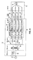
- the ground fault current in the plant or the cables feeding the plant can be calculated by measuring and summing with summers 210, 211, 212 all of the available currents 205, 206 207 in each thread 20-1, 20-2, 20-n as illustrated by circuit structure 200 of in FIG. 5 .
- the load (or generator) ground fault current 230 for the generator-side (load-side) may be calculated by further summing with summers 220, 225 the summations 215, 216 277 from the individual threads.
- Each summation of the individual thread currents includes the common mode component of current for that thread, but summation of the currents into a total ground fault current 230 in the above manner automatically compensates for the common mode current that can flow in each thread 20-1, 20-2, 20-n and produces a current signal that indicates the ground current for the plant or its conductors.
- An important aspect of the method is that the calculation can be turned off for any particular thread by an isolator 221, 222, 223 when that thread is taken out of service, allowing unimpeded operation of the remaining threads in the event that a thread is taken out of service and the current signals themselves for that thread are in error.
- ground fault function 280 may be triggered in response. This threshold level must be based on the smallest component in the branch and is typically driven by size of the conductors used to interconnection each thread to the plant.
- ground fault detection scheme One of the important aspects of a ground fault detection scheme is the impact that current sensor errors have on the calculation of the ground current. It can shown that offset errors in the current sensors that do not add to zero will cause a signal that is interpreted as a ground current. To improve the sensitivity of the ground fault detector, a further refinement in the calculation of the ground fault current can be made that ignores the dc component and detect the most likely component of ac current that will flow in a fault.
- Ground faults that occur in the plant will be fed by a voltage component that modulates with the terminal voltage of the plant, which is impressed by the intended operating condition of the system.
- a variable speed system will adjust both the amplitude and frequency of the plant's terminal voltage by controlling the power devices internal to the converter. This intended operating condition can be used to further refine the ground current calculation
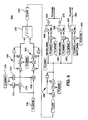
- FIG. 6 illustrates a circuit structure 300 to improve sensitivity of the ground fault calculation, in particular for a system with an ac output voltage.
- the total ground fault current 230 on the generator-side (load side) of the converter is multiplied 311, 312 against the in-phase and quadrature components, respectively, of the ground fault signal 310.
- These newly formed signals can then be filtered 320 and combined 325 to form ac ground fault signal 330.
- the ac ground fault signal may be filtered again 335 and compared with comparators 340, 350, 360 to threshold settings 345, 355, 365 which can indicate a fault alarm 370, 375 and fault trip 380 both for protection and diagnostic purposes.
- ground fault scheme above can calculate ground current on the load (generator) side of the thread current sensors but cannot distinguish fault current that flows to ground internal to a thread. This current is obscured by the previously mentioned common mode current and in order to calculate the internal ground fault current, the common mode current must be removed from the signal
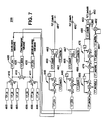
- Calculation of the internal ground current is accomplished by taking the difference in the common mode current on the grid side and the plant side (difference is result of the reference direction defined for currents) as illustrated in FIG. 7 .
- the ground fault current and common mode current internal to each converter thread is calculated as follows: The drawing below may represent the load-side currents phase 405 and the generator-side phase currents 406 from converter thread 20-1 of an exemplary multi-thread system. Again, it is desirable to limit operation of the converter system when an unintended current flows and to distinguish the source of the current.
- Line side phase currents 405 are summed in summer 410 and generator-side phase currents are summed in summer 411 to yield line side common mode current 420 and generator-side common mode current 430.
- Line side common mode current 420 and generator-side common mode current 430 are summed in summer 415 to yield the thread internal ground fault current 425.
- the above currents 420, 425, 430 are each conditioned with filters 440, 445, 450.
- Thread internal ground fault current 425 may be further squared 470 and filtered again 475.
- Currents 420, 425 and 430 may then be compared 462, 467, 483 against threshold limits 461, 466 and 481.
- An appropriate fault 491, 492, 493 is declared to constrain the operation of the system and form diagnostic information. In this case the calculations are done and a separate fault is declared for the current internal to each thread.
- Various aspects of the present invention include new methods of converter protection, which allow for system optimization, as well as, arc flash protection.
- One aspect of the present invention provides for coordinated fault sensing with means of removing applied to the converter so as to minimize the energy available to produce an arc flash event.
- Another aspect of this invention is positioning the sensing and disconnects for the protections close to the source of energy to protect more of the system.
- Converter control software and hardware is utilized to detect, identify and isolate faults using instrumentation native to the converter, in a novel way and extending the state or art beyond presently available "ground detection". Selecting the best combinations of the novel specific protections used, the components are moved into separate physical structures (e.g., cabinets) to enhance protection.
- the functional converter thread 20-1, 20-2, 20-3, 20-4 components may remain the same. While in specific embodiments physical placements of protection components may be identified as being located at specific locations such as power plant machinery (PPM) levels, the physical placement for such components need not be limited by these descriptions.
- PPM power plant machinery
- FIG. 8 illustrates a first preferred embodiment of the inventive protective arrangement for an integrated fault and personnel protection system 5.
- Fuse protection is provided on each side of the parallel converters (threads) 20-1 to 20-4.
- fuse protection is provided with a fuses 145 in-line with the generator side of each converter thread, the fuses being located at the converter enclosure.
- fuse protection is provided with a fuse 155 for each converter thread 20-1 to 20-4, where the fuses 155 are located remotely from the converter enclosure 22. Remote location of fuses 155 from the converter enclosure 22 may increase the likelihood that fuses will interrupt properly during fault conditions or arc flash within the converter that may create ionized gases causing arc-over the fuses if the fuses were positioned within the converter enclosure itself.
- Generator-side converter fuses 145 may also be positioned remote from the converter enclosure 22 based on the same rationale.
- the fuse protection may include semiconductor fuses including gS class fuses (as defined by the EN 60269-4 standard) delivering reliable I 2 t protection against all type of overloads.
- Arc flash protection for the front of the converter threads is enhanced by addition of covers to air inlets to the converter.
- At least one motor-operated breaker 125 may be positioned between the converter 20 and the generator 14.
- the embodiment illustrated in FIG. 8 includes a motor-operated circuit breaker 125 provided for each pair of converter threads.
- the motor-operated circuit breakers 125 may be physically located in a nacelle 160, in a machine head assembly 165, directly below the wind turbine generator 14, so as to provide the greatest amount of downstream fault protection.
- the motor-operated circuit breaker may be provided in any convenient location between the output of the generator 14 and a location where the generator wiring enters the tower.
- the trip setting for the motor-operated circuit breakers 125 may be set to coordinate for protection of the tower cables 15.
- the under voltage coil 177 for the motor-operated circuit breakers 125 may be tripped by the individual converter control system functions 175.
- the motor-operated circuit breakers 125 may alternatively be provided in other configurations, such as providing one motor-operated circuit breaker 125 to isolate the generator-side for each converter thread 20-1 to 20-4, as shown in FIG. 9 , or further be provided with as single breaker for isolation of all converter threads (not shown).
- the motor-operated circuit breakers 125 may also be tripped by a remote switch located in the tower lower level 12 to provide for lockout-tagout protection. Further the wind turbine generator cable entry area may be constructed so as to minimize the risk of arc flash.
- At least one motor-operated breaker 135 may be positioned between the converter 20 and the load 21.
- the motor-operated circuit breakers 135 may provide isolation for the converter 20 from power on the load-side of the converter coming from the grid or being provided from other wind turbine power systems in a common windfarm (not shown).
- a single motor-operated circuit breaker 135 may provide isolation for the load-side of the converter 20.
- the at least one motor-operated circuit breaker 135 may be preferentially located on the load-side of the load-side fuse protection for each converter thread. In other arrangements, a motor-operated circuit breaker 135 may be provided for each pair of converter threads (not shown).
- one motor-operated circuit breaker 135 may be provided on the load-side for each converter thread 20-1 to 20-4, as shown in FIG. 10 .
- the under voltage coil 177 for the motor-operated circuit breakers 135 may be tripped by the individual converter control system functions 175.
- a manually operated circuit breaker 90 may be provided on medium voltage switchgear (not shown) to isolate the wind turbine power system 10, including the converter, from power of the load 21.
- the load-side power may include power from the grid and power from other wind turbine power systems connected to a common windfarm.
- the under voltage coil for the circuit breaker on the MV switchgear may be tripped by a protective relay.
- a current transformer 183 for line current on the main transformer 85 and a current transformer 184 for neutral to ground line on the main transformer may provide current signal 181, 182 to the protective relay.
- the protective relay 180 may provide a trip signal 190 for instantaneous overcurrent and ground fault conditions to manually operated circuit breaker 90. Further, the protective relay 180 may be self-powered.
- FIG. 11 illustrates another further embodiment of an inventive protective arrangement using a current difference sensed between the individual converter threads and at the main transformer to activate a protective trip.
- a current transformer 183 may be provided at the main transformer 85.
- the current transformer 183 may provide a current signal 181 to protective relay 180, as previously described.
- the current transformer may also provide the current signal 181 to the converter control system 25.
- the converter control system 25 may provide fault protection due to high differential current in a thread, by comparing the individual thread current 189, as measured by current transformers 183 against the current sensed the main transformer 85.
- the converter control system may trip the motor- operated circuit breaker 135 on the load side of the converter, trip the motor-operated circuit breaker 125 on the generator-side of the converter 20, and/or the medium voltage switchgear circuit breaker 90.
- the differential current may be compared and measured by a supervisory monitoring relay such as 180 or by an electronic component within a control cabinet. Further, alternative locations may be provided for positioning of the current transformers within the system.
- another aspect of the invention incorporates modification to mitigate arc flash hazard.
- the modification includes improving covers for cable connections to minimize hazard to sides of the PDP enclosure. Covers may also be added to air inlets to minimize arc flash hazard in front of the enclosure. Fan ventilation may also be modified within the PDP to promote extinguishing arc flashes.
- covers may be added to air inlets to minimize arc flash hazard in the front of the enclosure.
- air ventilation may be enhanced to minimize arc flash hazard in front of the enclosure.
- the generator cable entry area may also be arranged to minimize the risk of arc flash by establishing separation between cable and entry components.
Applications Claiming Priority (1)
| Application Number | Priority Date | Filing Date | Title |
|---|---|---|---|
| US12/164,662 US7944068B2 (en) | 2008-06-30 | 2008-06-30 | Optimizing converter protection for wind turbine generators |
Publications (3)
| Publication Number | Publication Date |
|---|---|
| EP2141788A2 true EP2141788A2 (fr) | 2010-01-06 |
| EP2141788A3 EP2141788A3 (fr) | 2012-05-30 |
| EP2141788B1 EP2141788B1 (fr) | 2016-08-10 |
Family
ID=41210497
Family Applications (1)
| Application Number | Title | Priority Date | Filing Date |
|---|---|---|---|
| EP09163240.6A Not-in-force EP2141788B1 (fr) | 2008-06-30 | 2009-06-19 | Optimisation de protection de convertisseur pour générateurs d'éolienne |
Country Status (3)
| Country | Link |
|---|---|
| US (1) | US7944068B2 (fr) |
| EP (1) | EP2141788B1 (fr) |
| CN (1) | CN101635449B (fr) |
Cited By (10)
| Publication number | Priority date | Publication date | Assignee | Title |
|---|---|---|---|---|
| EP2463674A1 (fr) * | 2010-12-08 | 2012-06-13 | Siemens Aktiengesellschaft | Agencement et procédé de test d'un système de génération d'alimentation électrique |
| WO2012097825A1 (fr) * | 2011-01-21 | 2012-07-26 | Vestas Wind Systems A/S | Circuit de détection de défaillance d'une éolienne et procédé associé |
| EP2492502A1 (fr) * | 2011-02-25 | 2012-08-29 | Siemens Aktiengesellschaft | Éolienne dotée d'un générateur |
| WO2014113146A1 (fr) * | 2013-01-18 | 2014-07-24 | General Electroc Company | Connexion pour l'équilibrage amélioré de courant entre des circuits en pont parallèles |
| EP2698894A3 (fr) * | 2012-08-15 | 2016-08-10 | General Electric Company | Système de convertisseur de courant alternatif |
| EP2385367B1 (fr) * | 2010-05-05 | 2017-06-28 | Siemens Aktiengesellschaft | Agencement pour détecter une connexion électrique défectueuse |
| WO2021073704A1 (fr) * | 2019-10-16 | 2021-04-22 | Vestas Wind Systems A/S | Boîtier et procédure de sécurité moyenne tension |
| EP4063651A1 (fr) * | 2021-03-23 | 2022-09-28 | Vestas Wind Systems A/S | Système de convertisseur électrique protégé contre les défauts d'arc |
| US20230261476A1 (en) * | 2022-02-17 | 2023-08-17 | The Boeing Company | System and method for ground fault monitoring in an aircraft |
| US11894672B2 (en) | 2020-07-10 | 2024-02-06 | Vestas Wind Systems A/S | Wind turbine generator fault protection system |
Families Citing this family (68)
| Publication number | Priority date | Publication date | Assignee | Title |
|---|---|---|---|---|
| FI119086B (fi) * | 2006-11-06 | 2008-07-15 | Abb Oy | Menetelmä ja järjestely tuulivoimalan yhteydessä |
| JP2008306776A (ja) * | 2007-06-05 | 2008-12-18 | Hitachi Ltd | 風力発電システムおよびその制御方法 |
| US20110241630A1 (en) * | 2008-09-03 | 2011-10-06 | Exro Technologies Inc. | Power conversion system for a multi-stage generator |
| EP3128646A1 (fr) | 2009-01-16 | 2017-02-08 | Boulder Wind Power, Inc. | Stator segmenté pour dispositif à champ axial |
| WO2010132439A1 (fr) | 2009-05-12 | 2010-11-18 | Icr Turbine Engine Corporation | Système de stockage et de conversion d'énergie de turbine à gaz |
| CN101981310B (zh) * | 2009-06-05 | 2013-10-30 | 三菱重工业株式会社 | 风力发电装置及其控制方法、风力发电系统 |
| US8138620B2 (en) * | 2009-06-12 | 2012-03-20 | General Electric Company | Methods and systems for operating a wind turbine power converter |
| IT1397013B1 (it) * | 2009-11-03 | 2012-12-20 | Trevi Energy S P A | Sistema di controllo di centrali eoliche con aerogeneratori equipaggiati con convertitori modulari a corrente continua. |
| EP2346134B1 (fr) * | 2010-01-14 | 2017-09-27 | Siemens Aktiengesellschaft | Dispositif de convertisseur et procédé de conversion d'alimentation électrique |
| US8866334B2 (en) | 2010-03-02 | 2014-10-21 | Icr Turbine Engine Corporation | Dispatchable power from a renewable energy facility |
| US20110133743A1 (en) * | 2010-04-30 | 2011-06-09 | Werner Barton | Fault detection device and method for detecting an electrical fault |
| US9154024B2 (en) | 2010-06-02 | 2015-10-06 | Boulder Wind Power, Inc. | Systems and methods for improved direct drive generators |
| US8984895B2 (en) | 2010-07-09 | 2015-03-24 | Icr Turbine Engine Corporation | Metallic ceramic spool for a gas turbine engine |
| US8471534B2 (en) * | 2010-08-26 | 2013-06-25 | General Electric Company | Fault ride through switch for power generation system |
| CA2813680A1 (fr) | 2010-09-03 | 2012-03-08 | Icr Turbine Engine Corporation | Configurations de moteur a turbine a gaz |
| ES2398174B1 (es) * | 2010-09-09 | 2014-01-27 | Gamesa Innovation & Technology S.L. | Sistema de control de un convertidor. |
| FR2966652B1 (fr) * | 2010-10-21 | 2012-11-02 | Renault Sa | Dispositif et procede d'estimation d'un courant de toucher et de protection d'un appareil electrique contre de tels courants de toucher |
| US8553376B2 (en) * | 2010-12-11 | 2013-10-08 | The Boeing Company | Synchronous rectified PWM regulator with auto fault clearing |
| US8957535B2 (en) * | 2011-01-17 | 2015-02-17 | Vestas Wind Systems A/S | Fault tolerant wind turbine converter |
| EP2492504B1 (fr) * | 2011-02-25 | 2018-01-31 | Siemens Aktiengesellschaft | Éolienne |
| US9051873B2 (en) | 2011-05-20 | 2015-06-09 | Icr Turbine Engine Corporation | Ceramic-to-metal turbine shaft attachment |
| EP2528184B1 (fr) * | 2011-05-25 | 2014-09-10 | Siemens Aktiengesellschaft | Procédé et appareil de contrôle d'une liaison de transmission CC |
| EP2568560B1 (fr) * | 2011-09-07 | 2014-12-31 | Siemens Aktiengesellschaft | Convertisseur de fréquence et procédé de reconnaissance et de blocage d'un courant de fuite dans un convertisseur de fréquence |
| EP2568557B1 (fr) * | 2011-09-07 | 2014-02-26 | Siemens Aktiengesellschaft | Procédé de fonctionnement d'un disjoncteur à courant de fuite et disjoncteur à courant de fuite pour un convertisseur de courant |
| US20120139256A1 (en) * | 2011-10-06 | 2012-06-07 | General Electric Company | Wind turbine installation with a self-contained power production component enclosure |
| US8693220B2 (en) | 2011-10-26 | 2014-04-08 | General Electric Company | System for improved wind turbine generator performance |
| CN102377117B (zh) * | 2011-12-12 | 2014-07-23 | 济南轨道交通装备有限责任公司 | 风力发电机变压器维护保护系统 |
| US9184584B2 (en) | 2011-12-29 | 2015-11-10 | General Electric Company | Device and system for reducing overvoltage damange |
| CN104094493A (zh) * | 2011-12-29 | 2014-10-08 | 维斯塔斯风力系统集团公司 | 风力涡轮发电机 |
| GB201200803D0 (en) * | 2012-01-18 | 2012-02-29 | Rolls Royce Goodrich Engine Control Systems Ltd | Fault tolerant electric drive system |
| US9054599B2 (en) * | 2012-03-15 | 2015-06-09 | Rockwell Automation Technologies, Inc. | Power converter and integrated DC choke therefor |
| US10094288B2 (en) | 2012-07-24 | 2018-10-09 | Icr Turbine Engine Corporation | Ceramic-to-metal turbine volute attachment for a gas turbine engine |
| US8988841B2 (en) * | 2012-09-06 | 2015-03-24 | Siemens Aktiengesellschaft | Apparatus and methods for input protection for power converters |
| US9019673B2 (en) * | 2012-09-27 | 2015-04-28 | Rajiv Kumar Varma | Fault detection and short circuit current management technique for inverter based distributed generators (DG) |
| US9684328B2 (en) | 2012-12-21 | 2017-06-20 | General Electric Company | Systems and methods for overvoltage protection of power converters |
| US9343991B2 (en) | 2013-01-18 | 2016-05-17 | General Electric Company | Current balance control for non-interleaved parallel bridge circuits in power converter |
| US9281761B2 (en) | 2013-01-18 | 2016-03-08 | General Electric Company | Control scheme for current balancing between parallel bridge circuits |
| US9537437B2 (en) | 2013-03-04 | 2017-01-03 | General Electric Company | Method and system for controlling switching frequency of a doubly-fed induction generator (DFIG) |
| US8736133B1 (en) | 2013-03-14 | 2014-05-27 | Boulder Wind Power, Inc. | Methods and apparatus for overlapping windings |
| US9048764B2 (en) * | 2013-05-29 | 2015-06-02 | General Electric Company | Connection for improved current balancing in a parallel bridge power converter |
| US9362859B2 (en) | 2013-09-25 | 2016-06-07 | General Electric Company | System and method for controlling switching elements within a single-phase bridge circuit |
| US9577557B2 (en) | 2013-10-18 | 2017-02-21 | Abb Schweiz Ag | Turbine-generator system with DC output |
| US9614457B2 (en) * | 2013-10-18 | 2017-04-04 | Abb Schweiz Ag | Modular thyristor-based rectifier circuits |
| US9334749B2 (en) | 2013-10-18 | 2016-05-10 | Abb Technology Ag | Auxiliary power system for turbine-based energy generation system |
| US9755458B2 (en) | 2013-12-19 | 2017-09-05 | Kohler, Co. | Bus recovery after overload |
| US10177620B2 (en) | 2014-05-05 | 2019-01-08 | Boulder Wind Power, Inc. | Methods and apparatus for segmenting a machine |
| FI126063B (en) * | 2014-05-21 | 2016-06-15 | Vacon Oy | Limiting electrical interference |
| US9318283B2 (en) * | 2014-05-22 | 2016-04-19 | Siemens Aktiengesellschaft | Apparatus including a circuit breaker adapted to selectively provide arc flash protection in connection with a wind turbine |
| EP3213383B1 (fr) | 2014-10-27 | 2019-12-04 | Vestas Wind Systems A/S | Régulation de convertisseur d'éolienne pour convertisseurs à chaînes modulaires |
| EP3070805B1 (fr) | 2015-03-19 | 2021-04-28 | General Electric Technology GmbH | Réseau de transmission de puissance |
| US10171074B2 (en) * | 2015-10-01 | 2019-01-01 | Chicony Power Technology Co., Ltd. | Electronic system |
| US10063089B2 (en) * | 2015-12-11 | 2018-08-28 | National Chung-Shan Institute Of Science & Technology | Wind power charging circuit with three-phase, single-stage and bridgeless framework |
| US9893563B2 (en) * | 2016-02-10 | 2018-02-13 | General Electric Company | System and method for operating a wind turbine |
| DE102016108394A1 (de) * | 2016-05-06 | 2017-11-09 | Wobben Properties Gmbh | Verfahren zur Kompensation von einzuspeisenden Strömen eines Windparks |
| EP3267448A1 (fr) | 2016-07-08 | 2018-01-10 | ABB Schweiz AG | Dispositif d'isolation supplémentaire permettant de faire fonctionner à distance un disjoncteur pour équipement électrique |
| US10468885B2 (en) * | 2016-07-14 | 2019-11-05 | Ge Energy Power Conversion Technology Ltd. | Battery storage system with integrated inverter |
| US10027240B1 (en) * | 2017-01-06 | 2018-07-17 | General Electric Company | Ground fault isolation for power converters with silicon carbide MOSFETs |
| DE102017106924A1 (de) * | 2017-03-30 | 2018-10-04 | Airbus Defence and Space GmbH | Elektrisches Versorgungssystem für ein Flugzeug mit einem gewöhnlichen Wechselspannungsnetzwerk und einem bipolaren Gleichspannungsnetzwerk |
| US10790770B2 (en) * | 2017-05-25 | 2020-09-29 | General Electric Company | Methods for operating electrical power systems |
| US10778112B2 (en) * | 2018-04-04 | 2020-09-15 | General Electric Company | DFIG converter with active filter |
| GB2585855A (en) * | 2019-07-17 | 2021-01-27 | Rolls Royce Plc | Fault-tolerant electrical drive |
| US10819261B1 (en) * | 2019-10-25 | 2020-10-27 | Schweitzer Engineering Laboratories, Inc. | Security improvements for electric power generator protection |
| TWI700883B (zh) * | 2019-11-27 | 2020-08-01 | 公準精密工業股份有限公司 | 微渦輪發電系統及其電力管理方法 |
| US11005401B1 (en) | 2020-06-19 | 2021-05-11 | General Electric Company | Methods for operating an inverter-based resource connected to a series-compensated transmission system |
| CN111525574B (zh) * | 2020-07-06 | 2020-10-16 | 深圳华工能源技术有限公司 | 一种谐波抑制节能与三相不平衡治理节能协调控制方法 |
| CN113217281B (zh) * | 2021-05-11 | 2022-12-09 | 上海电气风电集团股份有限公司 | 风力发电系统及其控制方法、装置、电子设备、存储介质 |
| CN113765061A (zh) * | 2021-08-30 | 2021-12-07 | 华能江阴燃机热电有限责任公司 | 一种发电机拖动阶段保护方法 |
| WO2024025553A1 (fr) | 2022-07-29 | 2024-02-01 | General Electric Company | Systèmes et procédés de fonctionnement de ressources à base d'onduleur à l'aide de motifs d'impulsions d'entrelacement |
Citations (4)
| Publication number | Priority date | Publication date | Assignee | Title |
|---|---|---|---|---|
| WO2001082444A1 (fr) * | 2000-04-20 | 2001-11-01 | The Power Generation Company Ltd. | Appareil de protection d'un generateur |
| EP1523088A2 (fr) * | 2003-10-08 | 2005-04-13 | ABB Oy | Convertisseur pour réseau et sa méthode d'utilisation |
| WO2007003183A1 (fr) * | 2005-07-01 | 2007-01-11 | Vestas Wind Systems A/S | Turbine eolienne a vitesse de rotor variable, centrale eolienne, procede de transmission d’energie electrique et procede d’entretien ou d’inspection d’une turbine eolienne a vitesse de rotor variable |
| EP1768223A2 (fr) * | 2005-09-27 | 2007-03-28 | Gamesa Innovation & Technology, S.L. Unipersonal | Procédé de mise en oeuvre d'un système convertisseur |
Family Cites Families (12)
| Publication number | Priority date | Publication date | Assignee | Title |
|---|---|---|---|---|
| US4274043A (en) * | 1978-12-21 | 1981-06-16 | The Dow Chemical Company | Efficient, high power battery module; D.C. transformers and multi-terminal D.C. power networks utilizing same |
| DE10327344A1 (de) * | 2003-06-16 | 2005-01-27 | Repower Systems Ag | Windenergieanlage |
| EP1499009B1 (fr) * | 2003-07-15 | 2007-10-31 | Gamesa Innovation & Technology, S.L. Unipersonal | Commande et protection d'un système générateur à induction à double alimentation |
| US7446435B2 (en) * | 2005-11-30 | 2008-11-04 | General Electric Company | Power converter system and method |
| US7508089B2 (en) * | 2006-03-16 | 2009-03-24 | International Components Corporation | Over speed control circuit for a wind turbine generator which maximizes the power exported from the generator over time |
| DE102007017543B4 (de) * | 2006-04-10 | 2012-12-13 | Technische Universität Graz | Verfahren zur Entfernungsortung von Erdschlüssen |
| FI119212B (fi) * | 2006-12-14 | 2008-08-29 | Abb Oy | Taajuusmuuttajan maasulkusuojaus |
| EP1965483B1 (fr) * | 2007-02-27 | 2015-07-08 | SMA Solar Technology AG | Circuit pour la connexion d'une installation de génération d'énegie au réseau électrique |
| US7939959B2 (en) * | 2008-06-30 | 2011-05-10 | General Electric Company | Wind turbine with parallel converters utilizing a plurality of isolated transformer windings |
| US7928592B2 (en) * | 2008-06-30 | 2011-04-19 | General Electric Company | Wind turbine with parallel converters utilizing a plurality of isolated generator windings |
| US8643215B2 (en) * | 2009-03-11 | 2014-02-04 | Schweitzer Engineering Laboratories Inc | Mobile auxilliary power system for electrical distribution and transmission systems |
| US7782015B1 (en) * | 2009-07-30 | 2010-08-24 | Billy Joe Aaron | Electric power system |
-
2008
- 2008-06-30 US US12/164,662 patent/US7944068B2/en active Active
-
2009
- 2009-06-19 EP EP09163240.6A patent/EP2141788B1/fr not_active Not-in-force
- 2009-06-30 CN CN2009101594311A patent/CN101635449B/zh active Active
Patent Citations (4)
| Publication number | Priority date | Publication date | Assignee | Title |
|---|---|---|---|---|
| WO2001082444A1 (fr) * | 2000-04-20 | 2001-11-01 | The Power Generation Company Ltd. | Appareil de protection d'un generateur |
| EP1523088A2 (fr) * | 2003-10-08 | 2005-04-13 | ABB Oy | Convertisseur pour réseau et sa méthode d'utilisation |
| WO2007003183A1 (fr) * | 2005-07-01 | 2007-01-11 | Vestas Wind Systems A/S | Turbine eolienne a vitesse de rotor variable, centrale eolienne, procede de transmission d’energie electrique et procede d’entretien ou d’inspection d’une turbine eolienne a vitesse de rotor variable |
| EP1768223A2 (fr) * | 2005-09-27 | 2007-03-28 | Gamesa Innovation & Technology, S.L. Unipersonal | Procédé de mise en oeuvre d'un système convertisseur |
Cited By (12)
| Publication number | Priority date | Publication date | Assignee | Title |
|---|---|---|---|---|
| EP2385367B1 (fr) * | 2010-05-05 | 2017-06-28 | Siemens Aktiengesellschaft | Agencement pour détecter une connexion électrique défectueuse |
| EP2463674A1 (fr) * | 2010-12-08 | 2012-06-13 | Siemens Aktiengesellschaft | Agencement et procédé de test d'un système de génération d'alimentation électrique |
| WO2012097825A1 (fr) * | 2011-01-21 | 2012-07-26 | Vestas Wind Systems A/S | Circuit de détection de défaillance d'une éolienne et procédé associé |
| US9568532B2 (en) | 2011-01-21 | 2017-02-14 | Vestas Wind Systems A/S | Wind turbine fault detection circuit and method |
| EP2492502A1 (fr) * | 2011-02-25 | 2012-08-29 | Siemens Aktiengesellschaft | Éolienne dotée d'un générateur |
| US8766467B2 (en) | 2011-02-25 | 2014-07-01 | Siemens Aktiengesellschaft | Wind turbine with a generator |
| EP2698894A3 (fr) * | 2012-08-15 | 2016-08-10 | General Electric Company | Système de convertisseur de courant alternatif |
| WO2014113146A1 (fr) * | 2013-01-18 | 2014-07-24 | General Electroc Company | Connexion pour l'équilibrage amélioré de courant entre des circuits en pont parallèles |
| WO2021073704A1 (fr) * | 2019-10-16 | 2021-04-22 | Vestas Wind Systems A/S | Boîtier et procédure de sécurité moyenne tension |
| US11894672B2 (en) | 2020-07-10 | 2024-02-06 | Vestas Wind Systems A/S | Wind turbine generator fault protection system |
| EP4063651A1 (fr) * | 2021-03-23 | 2022-09-28 | Vestas Wind Systems A/S | Système de convertisseur électrique protégé contre les défauts d'arc |
| US20230261476A1 (en) * | 2022-02-17 | 2023-08-17 | The Boeing Company | System and method for ground fault monitoring in an aircraft |
Also Published As
| Publication number | Publication date |
|---|---|
| US7944068B2 (en) | 2011-05-17 |
| CN101635449A (zh) | 2010-01-27 |
| EP2141788B1 (fr) | 2016-08-10 |
| US20090322083A1 (en) | 2009-12-31 |
| EP2141788A3 (fr) | 2012-05-30 |
| CN101635449B (zh) | 2013-12-18 |
Similar Documents
| Publication | Publication Date | Title |
|---|---|---|
| US7944068B2 (en) | Optimizing converter protection for wind turbine generators | |
| Hooshyar et al. | Microgrid protection | |
| DK2341607T3 (en) | System for electrical control and operation of wind turbine | |
| US10483865B2 (en) | Converters for wind turbine generators | |
| EP2698894B1 (fr) | Système de convertisseur de courant alternatif | |
| Salomonsson et al. | Protection of low-voltage DC microgrids | |
| EP2665929B1 (fr) | Circuit de détection de défaillance d'une éolienne et procédé associé | |
| US10396695B2 (en) | Method for protecting an electrical power system | |
| CN101995529A (zh) | 用于风力涡轮发电机中的电力滤波器的监视以及电力滤波器失效的检测的系统和方法 | |
| US9088150B2 (en) | Overvoltage clipping device for a wind turbine and method | |
| Atkinson et al. | A doubly-fed induction generator test facility for grid fault ride-through analysis | |
| US8451573B1 (en) | Overvoltage protection device for a wind turbine and method | |
| Mohanty et al. | Current restrained undervoltage protection scheme of converter dominated microgrids | |
| CN110352549B (zh) | 具有碳化硅mosfet的功率转换器的接地故障隔离 | |
| EP3547476B1 (fr) | Dispositif de protection contre les surtensions d'un système de génération d'énergie à vitesse variable | |
| EP3788689A1 (fr) | Procédé de protection d'un système d'alimentation électrique | |
| CN112054524B (zh) | 电气装置的保护 | |
| Wang | Enhanced protection and location techniques for enabling wider implementation of LVDC distribution networks | |
| Polat et al. | Analysis and a Proposed Protection Technique of Phase Unbalance on Induction Motors in an Oil-Gas Plant | |
| Emhemed et al. | Protection and earthing requirements of low voltage AC and DC distribution networks interfaced by smart transformers | |
| Ivanova | Transient analysis of road tunnel power system | |
| US20210389385A1 (en) | Detecting device and method for detecting a fault in a transformer of a wind turbine | |
| KR101759595B1 (ko) | Ac선로와 dc선로가 병가된 송전선로의 선간 접촉 보호 시스템 | |
| Lynch et al. | Flexible DER Utility Interface System: Final Report, September 2004--May 2006 |
Legal Events
| Date | Code | Title | Description |
|---|---|---|---|
| PUAI | Public reference made under article 153(3) epc to a published international application that has entered the european phase |
Free format text: ORIGINAL CODE: 0009012 |
|
| AK | Designated contracting states |
Kind code of ref document: A2 Designated state(s): AT BE BG CH CY CZ DE DK EE ES FI FR GB GR HR HU IE IS IT LI LT LU LV MC MK MT NL NO PL PT RO SE SI SK TR |
|
| PUAL | Search report despatched |
Free format text: ORIGINAL CODE: 0009013 |
|
| AK | Designated contracting states |
Kind code of ref document: A3 Designated state(s): AT BE BG CH CY CZ DE DK EE ES FI FR GB GR HR HU IE IS IT LI LT LU LV MC MK MT NL NO PL PT RO SE SI SK TR |
|
| AX | Request for extension of the european patent |
Extension state: AL BA RS |
|
| RIC1 | Information provided on ipc code assigned before grant |
Ipc: H02H 7/12 20060101ALI20120425BHEP Ipc: H02J 3/38 20060101ALI20120425BHEP Ipc: F03D 9/00 20060101ALI20120425BHEP Ipc: H02H 7/10 20060101ALI20120425BHEP Ipc: H02M 1/32 20070101AFI20120425BHEP Ipc: H02P 9/00 20060101ALI20120425BHEP Ipc: H02H 7/122 20060101ALI20120425BHEP |
|
| 17P | Request for examination filed |
Effective date: 20121130 |
|
| 17Q | First examination report despatched |
Effective date: 20150724 |
|
| GRAP | Despatch of communication of intention to grant a patent |
Free format text: ORIGINAL CODE: EPIDOSNIGR1 |
|
| INTG | Intention to grant announced |
Effective date: 20160329 |
|
| GRAS | Grant fee paid |
Free format text: ORIGINAL CODE: EPIDOSNIGR3 |
|
| GRAA | (expected) grant |
Free format text: ORIGINAL CODE: 0009210 |
|
| AK | Designated contracting states |
Kind code of ref document: B1 Designated state(s): AT BE BG CH CY CZ DE DK EE ES FI FR GB GR HR HU IE IS IT LI LT LU LV MC MK MT NL NO PL PT RO SE SI SK TR |
|
| REG | Reference to a national code |
Ref country code: GB Ref legal event code: FG4D |
|
| REG | Reference to a national code |
Ref country code: CH Ref legal event code: EP Ref country code: AT Ref legal event code: REF Ref document number: 819830 Country of ref document: AT Kind code of ref document: T Effective date: 20160815 |
|
| REG | Reference to a national code |
Ref country code: IE Ref legal event code: FG4D |
|
| REG | Reference to a national code |
Ref country code: DE Ref legal event code: R096 Ref document number: 602009040186 Country of ref document: DE |
|
| REG | Reference to a national code |
Ref country code: LT Ref legal event code: MG4D |
|
| REG | Reference to a national code |
Ref country code: NL Ref legal event code: MP Effective date: 20160810 |
|
| REG | Reference to a national code |
Ref country code: AT Ref legal event code: MK05 Ref document number: 819830 Country of ref document: AT Kind code of ref document: T Effective date: 20160810 |
|
| PG25 | Lapsed in a contracting state [announced via postgrant information from national office to epo] |
Ref country code: IS Free format text: LAPSE BECAUSE OF FAILURE TO SUBMIT A TRANSLATION OF THE DESCRIPTION OR TO PAY THE FEE WITHIN THE PRESCRIBED TIME-LIMIT Effective date: 20161210 Ref country code: IT Free format text: LAPSE BECAUSE OF FAILURE TO SUBMIT A TRANSLATION OF THE DESCRIPTION OR TO PAY THE FEE WITHIN THE PRESCRIBED TIME-LIMIT Effective date: 20160810 Ref country code: NO Free format text: LAPSE BECAUSE OF FAILURE TO SUBMIT A TRANSLATION OF THE DESCRIPTION OR TO PAY THE FEE WITHIN THE PRESCRIBED TIME-LIMIT Effective date: 20161110 Ref country code: HR Free format text: LAPSE BECAUSE OF FAILURE TO SUBMIT A TRANSLATION OF THE DESCRIPTION OR TO PAY THE FEE WITHIN THE PRESCRIBED TIME-LIMIT Effective date: 20160810 Ref country code: NL Free format text: LAPSE BECAUSE OF FAILURE TO SUBMIT A TRANSLATION OF THE DESCRIPTION OR TO PAY THE FEE WITHIN THE PRESCRIBED TIME-LIMIT Effective date: 20160810 Ref country code: LT Free format text: LAPSE BECAUSE OF FAILURE TO SUBMIT A TRANSLATION OF THE DESCRIPTION OR TO PAY THE FEE WITHIN THE PRESCRIBED TIME-LIMIT Effective date: 20160810 Ref country code: FI Free format text: LAPSE BECAUSE OF FAILURE TO SUBMIT A TRANSLATION OF THE DESCRIPTION OR TO PAY THE FEE WITHIN THE PRESCRIBED TIME-LIMIT Effective date: 20160810 |
|
| PG25 | Lapsed in a contracting state [announced via postgrant information from national office to epo] |
Ref country code: AT Free format text: LAPSE BECAUSE OF FAILURE TO SUBMIT A TRANSLATION OF THE DESCRIPTION OR TO PAY THE FEE WITHIN THE PRESCRIBED TIME-LIMIT Effective date: 20160810 Ref country code: GR Free format text: LAPSE BECAUSE OF FAILURE TO SUBMIT A TRANSLATION OF THE DESCRIPTION OR TO PAY THE FEE WITHIN THE PRESCRIBED TIME-LIMIT Effective date: 20161111 Ref country code: ES Free format text: LAPSE BECAUSE OF FAILURE TO SUBMIT A TRANSLATION OF THE DESCRIPTION OR TO PAY THE FEE WITHIN THE PRESCRIBED TIME-LIMIT Effective date: 20160810 Ref country code: SE Free format text: LAPSE BECAUSE OF FAILURE TO SUBMIT A TRANSLATION OF THE DESCRIPTION OR TO PAY THE FEE WITHIN THE PRESCRIBED TIME-LIMIT Effective date: 20160810 Ref country code: PT Free format text: LAPSE BECAUSE OF FAILURE TO SUBMIT A TRANSLATION OF THE DESCRIPTION OR TO PAY THE FEE WITHIN THE PRESCRIBED TIME-LIMIT Effective date: 20161212 Ref country code: LV Free format text: LAPSE BECAUSE OF FAILURE TO SUBMIT A TRANSLATION OF THE DESCRIPTION OR TO PAY THE FEE WITHIN THE PRESCRIBED TIME-LIMIT Effective date: 20160810 Ref country code: PL Free format text: LAPSE BECAUSE OF FAILURE TO SUBMIT A TRANSLATION OF THE DESCRIPTION OR TO PAY THE FEE WITHIN THE PRESCRIBED TIME-LIMIT Effective date: 20160810 |
|
| PG25 | Lapsed in a contracting state [announced via postgrant information from national office to epo] |
Ref country code: EE Free format text: LAPSE BECAUSE OF FAILURE TO SUBMIT A TRANSLATION OF THE DESCRIPTION OR TO PAY THE FEE WITHIN THE PRESCRIBED TIME-LIMIT Effective date: 20160810 Ref country code: RO Free format text: LAPSE BECAUSE OF FAILURE TO SUBMIT A TRANSLATION OF THE DESCRIPTION OR TO PAY THE FEE WITHIN THE PRESCRIBED TIME-LIMIT Effective date: 20160810 |
|
| REG | Reference to a national code |
Ref country code: DE Ref legal event code: R097 Ref document number: 602009040186 Country of ref document: DE |
|
| PG25 | Lapsed in a contracting state [announced via postgrant information from national office to epo] |
Ref country code: BE Free format text: LAPSE BECAUSE OF FAILURE TO SUBMIT A TRANSLATION OF THE DESCRIPTION OR TO PAY THE FEE WITHIN THE PRESCRIBED TIME-LIMIT Effective date: 20160810 Ref country code: DK Free format text: LAPSE BECAUSE OF FAILURE TO SUBMIT A TRANSLATION OF THE DESCRIPTION OR TO PAY THE FEE WITHIN THE PRESCRIBED TIME-LIMIT Effective date: 20160810 Ref country code: CZ Free format text: LAPSE BECAUSE OF FAILURE TO SUBMIT A TRANSLATION OF THE DESCRIPTION OR TO PAY THE FEE WITHIN THE PRESCRIBED TIME-LIMIT Effective date: 20160810 Ref country code: SK Free format text: LAPSE BECAUSE OF FAILURE TO SUBMIT A TRANSLATION OF THE DESCRIPTION OR TO PAY THE FEE WITHIN THE PRESCRIBED TIME-LIMIT Effective date: 20160810 Ref country code: BG Free format text: LAPSE BECAUSE OF FAILURE TO SUBMIT A TRANSLATION OF THE DESCRIPTION OR TO PAY THE FEE WITHIN THE PRESCRIBED TIME-LIMIT Effective date: 20161110 |
|
| PLBE | No opposition filed within time limit |
Free format text: ORIGINAL CODE: 0009261 |
|
| STAA | Information on the status of an ep patent application or granted ep patent |
Free format text: STATUS: NO OPPOSITION FILED WITHIN TIME LIMIT |
|
| 26N | No opposition filed |
Effective date: 20170511 |
|
| PG25 | Lapsed in a contracting state [announced via postgrant information from national office to epo] |
Ref country code: SI Free format text: LAPSE BECAUSE OF FAILURE TO SUBMIT A TRANSLATION OF THE DESCRIPTION OR TO PAY THE FEE WITHIN THE PRESCRIBED TIME-LIMIT Effective date: 20160810 |
|
| REG | Reference to a national code |
Ref country code: DE Ref legal event code: R119 Ref document number: 602009040186 Country of ref document: DE |
|
| PG25 | Lapsed in a contracting state [announced via postgrant information from national office to epo] |
Ref country code: MC Free format text: LAPSE BECAUSE OF FAILURE TO SUBMIT A TRANSLATION OF THE DESCRIPTION OR TO PAY THE FEE WITHIN THE PRESCRIBED TIME-LIMIT Effective date: 20160810 |
|
| REG | Reference to a national code |
Ref country code: CH Ref legal event code: PL |
|
| GBPC | Gb: european patent ceased through non-payment of renewal fee |
Effective date: 20170619 |
|
| REG | Reference to a national code |
Ref country code: IE Ref legal event code: MM4A |
|
| REG | Reference to a national code |
Ref country code: FR Ref legal event code: ST Effective date: 20180228 |
|
| PG25 | Lapsed in a contracting state [announced via postgrant information from national office to epo] |
Ref country code: DE Free format text: LAPSE BECAUSE OF NON-PAYMENT OF DUE FEES Effective date: 20180103 Ref country code: GB Free format text: LAPSE BECAUSE OF NON-PAYMENT OF DUE FEES Effective date: 20170619 Ref country code: LI Free format text: LAPSE BECAUSE OF NON-PAYMENT OF DUE FEES Effective date: 20170630 Ref country code: IE Free format text: LAPSE BECAUSE OF NON-PAYMENT OF DUE FEES Effective date: 20170619 Ref country code: LU Free format text: LAPSE BECAUSE OF NON-PAYMENT OF DUE FEES Effective date: 20170619 Ref country code: CH Free format text: LAPSE BECAUSE OF NON-PAYMENT OF DUE FEES Effective date: 20170630 |
|
| PG25 | Lapsed in a contracting state [announced via postgrant information from national office to epo] |
Ref country code: FR Free format text: LAPSE BECAUSE OF NON-PAYMENT OF DUE FEES Effective date: 20170630 |
|
| PG25 | Lapsed in a contracting state [announced via postgrant information from national office to epo] |
Ref country code: MT Free format text: LAPSE BECAUSE OF NON-PAYMENT OF DUE FEES Effective date: 20170619 |
|
| PG25 | Lapsed in a contracting state [announced via postgrant information from national office to epo] |
Ref country code: HU Free format text: LAPSE BECAUSE OF FAILURE TO SUBMIT A TRANSLATION OF THE DESCRIPTION OR TO PAY THE FEE WITHIN THE PRESCRIBED TIME-LIMIT; INVALID AB INITIO Effective date: 20090619 |
|
| PG25 | Lapsed in a contracting state [announced via postgrant information from national office to epo] |
Ref country code: CY Free format text: LAPSE BECAUSE OF NON-PAYMENT OF DUE FEES Effective date: 20160810 |
|
| PG25 | Lapsed in a contracting state [announced via postgrant information from national office to epo] |
Ref country code: MK Free format text: LAPSE BECAUSE OF FAILURE TO SUBMIT A TRANSLATION OF THE DESCRIPTION OR TO PAY THE FEE WITHIN THE PRESCRIBED TIME-LIMIT Effective date: 20160810 |
|
| PG25 | Lapsed in a contracting state [announced via postgrant information from national office to epo] |
Ref country code: TR Free format text: LAPSE BECAUSE OF FAILURE TO SUBMIT A TRANSLATION OF THE DESCRIPTION OR TO PAY THE FEE WITHIN THE PRESCRIBED TIME-LIMIT Effective date: 20160810 |