EP2141492A2 - Gas sensor - Google Patents
Gas sensor Download PDFInfo
- Publication number
- EP2141492A2 EP2141492A2 EP09008774A EP09008774A EP2141492A2 EP 2141492 A2 EP2141492 A2 EP 2141492A2 EP 09008774 A EP09008774 A EP 09008774A EP 09008774 A EP09008774 A EP 09008774A EP 2141492 A2 EP2141492 A2 EP 2141492A2
- Authority
- EP
- European Patent Office
- Prior art keywords
- conductor
- hole
- conductive portion
- lead
- ceramic
- Prior art date
- Legal status (The legal status is an assumption and is not a legal conclusion. Google has not performed a legal analysis and makes no representation as to the accuracy of the status listed.)
- Granted
Links
- 239000004020 conductor Substances 0.000 claims abstract description 218
- 239000000919 ceramic Substances 0.000 claims abstract description 90
- 230000002093 peripheral effect Effects 0.000 claims abstract description 75
- 239000010410 layer Substances 0.000 description 134
- 239000007789 gas Substances 0.000 description 54
- 239000007784 solid electrolyte Substances 0.000 description 42
- 239000011241 protective layer Substances 0.000 description 29
- QVGXLLKOCUKJST-UHFFFAOYSA-N atomic oxygen Chemical compound [O] QVGXLLKOCUKJST-UHFFFAOYSA-N 0.000 description 19
- 239000001301 oxygen Substances 0.000 description 19
- 229910052760 oxygen Inorganic materials 0.000 description 19
- 238000009413 insulation Methods 0.000 description 18
- 229910052751 metal Inorganic materials 0.000 description 16
- 239000002184 metal Substances 0.000 description 16
- 230000001012 protector Effects 0.000 description 11
- 238000012986 modification Methods 0.000 description 10
- 230000004048 modification Effects 0.000 description 10
- 230000000149 penetrating effect Effects 0.000 description 9
- 238000000034 method Methods 0.000 description 8
- 238000005259 measurement Methods 0.000 description 7
- 238000005245 sintering Methods 0.000 description 7
- 239000000454 talc Substances 0.000 description 7
- 229910052623 talc Inorganic materials 0.000 description 7
- PNEYBMLMFCGWSK-UHFFFAOYSA-N aluminium oxide Inorganic materials [O-2].[O-2].[O-2].[Al+3].[Al+3] PNEYBMLMFCGWSK-UHFFFAOYSA-N 0.000 description 6
- 238000001514 detection method Methods 0.000 description 5
- 238000010438 heat treatment Methods 0.000 description 5
- 239000000463 material Substances 0.000 description 5
- MCMNRKCIXSYSNV-UHFFFAOYSA-N Zirconium dioxide Chemical compound O=[Zr]=O MCMNRKCIXSYSNV-UHFFFAOYSA-N 0.000 description 4
- GWEVSGVZZGPLCZ-UHFFFAOYSA-N Titan oxide Chemical compound O=[Ti]=O GWEVSGVZZGPLCZ-UHFFFAOYSA-N 0.000 description 2
- 238000002788 crimping Methods 0.000 description 2
- 238000009792 diffusion process Methods 0.000 description 2
- 230000005484 gravity Effects 0.000 description 2
- 238000003780 insertion Methods 0.000 description 2
- 230000037431 insertion Effects 0.000 description 2
- 229910002077 partially stabilized zirconia Inorganic materials 0.000 description 2
- 229910001220 stainless steel Inorganic materials 0.000 description 2
- 239000010935 stainless steel Substances 0.000 description 2
- 239000011800 void material Substances 0.000 description 2
- 230000007797 corrosion Effects 0.000 description 1
- 238000005260 corrosion Methods 0.000 description 1
- 230000006866 deterioration Effects 0.000 description 1
- 230000001747 exhibiting effect Effects 0.000 description 1
- 239000000446 fuel Substances 0.000 description 1
- 238000004519 manufacturing process Methods 0.000 description 1
- 229910000510 noble metal Inorganic materials 0.000 description 1
- 230000035515 penetration Effects 0.000 description 1
- 238000007747 plating Methods 0.000 description 1
- 231100000572 poisoning Toxicity 0.000 description 1
- 230000000607 poisoning effect Effects 0.000 description 1
- 229910052596 spinel Inorganic materials 0.000 description 1
- 239000011029 spinel Substances 0.000 description 1
Images


Classifications
-
- G—PHYSICS
- G01—MEASURING; TESTING
- G01N—INVESTIGATING OR ANALYSING MATERIALS BY DETERMINING THEIR CHEMICAL OR PHYSICAL PROPERTIES
- G01N27/00—Investigating or analysing materials by the use of electric, electrochemical, or magnetic means
- G01N27/26—Investigating or analysing materials by the use of electric, electrochemical, or magnetic means by investigating electrochemical variables; by using electrolysis or electrophoresis
- G01N27/403—Cells and electrode assemblies
- G01N27/406—Cells and probes with solid electrolytes
- G01N27/407—Cells and probes with solid electrolytes for investigating or analysing gases
- G01N27/4071—Cells and probes with solid electrolytes for investigating or analysing gases using sensor elements of laminated structure
Definitions
- the present invention relates to a gas sensor including a stacked-type gas sensor including a plurality of stacked ceramic layers.
- a plate-shaped gas sensor including a plurality of stacked ceramic layers (solid electrolyte layers) and provided with an electrode (a sensing portion) on a leading end side thereof is known.
- Such a gas sensor generally includes a ceramic layer having an electrode formed on one surface thereof and a lead portion formed on an opposite side surface thereof, where the electrode and the lead portion are electrically interconnected by means of a through hole conductor formed in a through hole (a penetration hole) penetrating through the ceramic layers (see JP-A-61-134655 ).
- the ceramic layers are formed of green sheets. As shown in Fig. 11 , after a through hole 241h1 is bored in a ceramic layer 241, an unsintered through hole conductor 206 is formed on an inner peripheral surface of the through hole 241h1, and an unsintered peripheral conductive portion 206S is formed at a periphery of the through hole 241 h. Similarly, after a through hole 221h1 is bored in a ceramic layer 221 opposing the ceramic layer 241, an unsintered through hole conductor 226 is formed on an inner peripheral surface of the through hole 221h1, and an unsintered peripheral conductive portion 226S is additionally formed at a periphery of the through hole 221h1.
- the ceramic layers 221 and 241 are stacked in such a way that the peripheral conductive portions 206S and 226S of the respective ceramic layers 221 and 241 contact one another, and are thereby electrically connected.
- the ceramic green sheet and the unsintered metalized layer differ from each other in the amount of sintering shrinkage. For this reason, deformation, such as warpage in the peripheral conductive portions 206S and 226S, may occur during a sintering operation, and a clearance CL may be generated between opposing members, which results in a deterioration of electrical connection reliability.
- a technique for providing elongated conductive portions 247, 222 extending from the respective peripheral conductive portions 206S and 226S to surfaces of the respective ceramic layer 221 and 241 and for establishing electrical connection between the elongated conductive portions 247, 222 which are not subject to warpage (which are not subject to the clearance CL between opposing members) (see JP-A-2008-46112 ).
- the elongated conductive portions contain components different from that of the ceramic layers, adhesion between adjacent ceramic layers may decrease as the portion of the elongated conductive portions increases.
- the invention was made in consideration of the above noted problems of the prior art, and an object thereof is to provide a gas sensor including a conductor which exhibits higher electrical connection reliability with another conductor, which allows for a reduction in the amount of conductive material that is used, and which also enhances adhesion between ceramic layers.
- a gas sensor 100 comprising: a plate-shaped gas sensing element 200 extending in a longitudinal direction and comprising a sensing portion 200s provided at a leading-end side in the longitudinal direction, the gas sensing element 200 comprising a plurality of stacked ceramic layers 211, 221, 231, 241 including a first ceramic layer 241 having a first surface and a second ceramic layer 221 having a second surface opposing the first surface, wherein the first ceramic layer 241 has a first through hole 241h1, a first through hole conductor 271 covering at least an inner surface of the first through hole 241h1, wherein the first ceramic layer 241 comprises a first conductor 247 formed on the first surface thereof, wherein the first conductor 247 comprises: a first peripheral conductive portion 247c provided at a periphery of the first through hole 241h1 and electrically connected to the first through hole conductor 221; a first lead portion 247b that is narrower than the first
- the first contact conductive portion of the first conductor is electrically connected to the second conductor.
- the essential requirement for the first lead portion provided between the first peripheral conductive portion and the first contact conductive portion is to establish electrical conduction between the first peripheral conductive portion and the first contact conductive portion. Therefore, since the first lead portion is provided with a narrow width, the amount of conductive material used can be reduced when compared with a case where the entirety of the first conductor is provided with a given width. Moreover, when the first lead portion is provided with a narrow width, an exposed area of the first ceramic layer having no first conductor is increased. Consequently, adhesion between the first ceramic layer and the second ceramic layer opposing each other is enhanced.
- the first contact conductive portion having a relatively greater area is located away from the first peripheral conductive portion provided at a peripheral of the through hole that is likely to deform during a sintering process, the reliability of electrical connection with the second conductor is enhanced.
- the second ceramic layer 221 may have a second through hole 221h1 with a second through hole conductor 226 covering at least an inner surface of the second through hole, the second through hole being connected to the first through hole 241h1, wherein the second conductor 222 comprises: a second peripheral conductive portion 222c provided at a periphery of the second through hole 221h1 and electrically connected to the second through hole conductor 226; a second lead portion 222b that is narrower than the second peripheral conductive portion 222c; and a second contact conductive portion 222a that is wider than the second lead portion 222b, wherein the second peripheral conductive portion 222c, the second lead portion 222b and the second contact conductive portion 222a may be integrally formed and arranged in this order in the longitudinal direction, and wherein at least the first contact conductive portion 247a and the second contact conductive portion 222a are electrically connected to each other.
- the second lead portion of the second conductor opposing the first conductor is also narrowed similar to the first lead portion.
- the amount of conductive material used is reduced, and adhesion between the first ceramic layer and the second ceramic layer is enhanced.
- first lead portion 247b and/or a second lead portion 222b comprises a plurality of separated conductors extending in the longitudinal direction and electrically connecting the first peripheral conductive portion 247c and the first contact conductive portion 247a.
- the first contact conductive portion 247a and/or the second contact conductive portion 222a has a loop shape.
- the outer dimensions of the first and second contact conductive portions can be increased. Therefore, even when a slight misalignment has occurred at a stacking process of the ceramic layers, the first and second contact conductive portions can reliably contact their opposing conductors.
- the first contact conductive portion 247a has a larger area than that of the first peripheral conductive portion 247c, and/or the second contact conductive portion 222a has an area larger than that of the second peripheral conductive portion 222c.
- the term "main component” means a component contained in an amount of 50 mass% or more.
- the gas sensor includes conductors which can exhibit higher electrical connection reliability, which can lead to a further reduction in the amount of conductive material that is used, and which can also enhance adhesion between ceramic layers.
- Fig. 1 is a cross-sectional view showing the configuration of an oxygen sensor (a gas sensor) of an embodiment of the present invention
- Fig. 2 is an exploded perspective view showing the configuration of a gas sensor
- Fig. 3 is a view showing a cross-sectional configuration of a through hole along line A;
- Fig. 4 is a view showing a cross-sectional configuration of a through hole along line B;
- Fig. 5 is a view showing a cross-sectional configuration of a through hole along line C;
- Fig. 6 is a partial perspective view showing a combination of a conductor with a conductor in the through hole along line A;
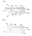
- Fig. 7 is a partial perspective view showing a combination of a conductor with a conductor in the through hole along line C;
- Fig. 8 is a top view showing a modification of the conductor
- Fig. 9 is a top view showing another modification of the conductor
- Fig. 10 is a top view showing yet another modification of the conductor.
- Fig. 11 is a view showing deformation, such as warpage, in a peripheral conductor upon sintering and a resulting clearance formed between the peripheral conductor and an opposing material.
- Fig. 1 shows an oxygen sensor (a gas sensor) 100 of an embodiment of the present invention.
- the oxygen sensor 100 is mounted on an exhaust pipe (not shown) of an automobile and senses the concentration of oxygen in an exhaust gas.
- a downward direction in Fig. 1 (a direction of a protector 125) is taken as a leading-end side of the oxygen sensor 100, and an upward direction in the same is taken as a base end of the oxygen sensor.
- the oxygen sensor 100 includes a gas sensing element 200, a cylindrical metal shell 103 holding the gas sensing element 200 therein, a protector 125 mounted at a predetermined position on the leading-end side of the metal shell 103, an outer cylinder 131 connected to the predetermined portion on a base-end side of the metal shell 103, and the like.
- the gas sensing element 200 is an elongated, plate-shaped, stacked-type element that has a leading end 200a and a base end 200b and that includes a plurality of stacked ceramic layers, and is provided with a sensing portion 200s (described below) in a leading end portion thereof.
- a dimension of the gas sensing element 200 of the present embodiment is about 40 mm in length x about 5 mm in width x about 1.2 mm in thickness.
- the metal shell 103 contains stainless steel such as SUS430.
- the metal shell 103 includes, in an outer surface thereof, an external thread portion 105 used for mounting the gas sensor 100 on the exhaust pipe and a hexagonal engagement portion 107 for engaging a tool during a mounting operation.
- the metal shell 103 includes, in an inner surface thereof, an inner step portion 109 inwardly protruding in a radial direction, so as to support a cylindrical metal holder 111 from an outside thereof.
- the metal holder 111 holds the gas sensing element 200.
- a ceramic holder 113 and a talc-filled layer 115 for positioning the gas sensing element 200 at a predetermined position are arranged in this order from the leading-end side.
- the talc-filled layer 115 includes, in the order from its leading-end side, a first talc-filled layer 116 and a second talc-filled layer 117.
- a cylindrical shaped multistage sleeve 119 containing alumina is disposed on a base end of the second talc-filled layer 117.
- the gas sensing element 200 is inserted into the ceramic holder 113, the talc-filled layer 115, and an axial hole 119h of the sleeve 119.
- the metal shell 103 includes a crimping portion 110 extending along a base end of the metal shell 103 so as to cover a base end of the sleeve 119.
- the sleeve 119 is pressed against the leading-end side of the metal shell 103 through a stainless-steel ring member 121, by inwardly folding the crimping portion 110, whereby the gas sensing element 200 is clamped and held by the ceramic holder 113, the talc-filled layer 115, and the like.
- the metal protector 125 is welded to an outer periphery of the leading end of the metal shell 103 so as to protrude from the leading end of the metal shell 103 and cover the sensing portion 200s of the gas sensing element 200.
- the protector 125 has a double structure including an outer protector 126 and an inner protector 127 provided inside the outer protector 126.
- Each of the outer protector 126 and the inner protector 127 is formed into a bottomed cylindrical shape having its leading end closed.
- the outer protector 126 has a plurality of gas introduction holes 126k which allow for introduction of exhaust gas from an outside to an inside thereof
- the inner protector 127 has a plurality of gas introduction holes 127k allowing for introduction of exhaust gas from an outside thereof to an inside thereof.
- the outer cylinder 131 is welded to an outer peripheral surface of the base end side of the metal shell 103, and a cylindrical separator 135 is arranged in the outer cylinder 131.
- the separator 135 has insertion holes for separately holding a plurality of lead wires 141 and a center hole for housing a base end of the gas sensing element 200 on the leading-end side of the separator 135.
- a plurality of connector fittings 139 are arranged so as to surround the center hole of the separator 135, and the connector fittings 139 are electrically connected to a terminal portions provided on the base end of the gas sensing element 200.
- the lead wires 141 extending from the respective connector fittings 139 are drawn out from a base end side of the gas sensor 100.
- a cylindrical spring-shaped holding member 137 extends radially outward and is disposed along an outer periphery of a leading end of the separator 135.
- the holding member 137 extends radially outward so as to contact an inner surface of the outer cylinder 131, whereby the separator 135 is fixed.
- a columnar rubber cap 143 is disposed on a base end of the separator 135 so as to close a base-end opening 131c of the outer cylinder 131.
- An outer periphery of the outer cylinder 131 is crimped inwardly in the radial direction while the rubber cap 143 remains attached to the outer cylinder 131, whereby the rubber cap 143 is fixed to the outer cylinder 131.
- a plurality of insertion holes 143h for inserting the lead wires 141 is formed in the rubber cap 143.
- the gas sensing element 200 includes a plurality of stacked ceramic layers 241, 221, 231 and 211 (which respectively correspond to a protective layer, a second solid electrolyte layer, an insulation layer, and a first solid electrolyte layer in Fig. 2 ). Through holes are used to establish electrical conduction among the ceramic layers 241, 221, 231 and 211.
- an arrow A denotes a through hole along line A for establishing electrical conduction from a connection portion 215c of a second electrode 215a formed on the first solid electrolyte layer 211 to a first electrode pad 243 formed on the protective layer 241.
- an arrow B denotes a through hole along line B for establishing electrical conduction from a connection portion 213c of a first electrode 213a formed on the first solid electrolyte layer 211 to a second electrode pad 244 formed on the protective layer 241.
- An arrow C denotes a through hole along line C for establishing electrical conduction from a connection portion 223c of a third electrode 223a formed on the second solid electrolyte layer 221 to a third electrode pad 245 formed on the protective layer 241.
- the electrode pads 243 to 245 are connected to the respective connector fittings 139 provided on the gas sensor main body (see Fig. 1 ).
- conductors 247, 222 provided corresponding to respective through holes of the protective layer 241 and the second solid electrolyte layer 221 opposing each other are, for example, formed to have a specific shape, whereby electrical connection reliability achieved when the layers are superimposed one on top of the other is enhanced, and the amount of conductive material that is used is reduced.
- a specific configuration of the conductor will be described below.
- the gas sensing element 200 includes a sensor portion 201 configured to sensing the concentration of oxygen and a heater 251 for heating the sensor portion 201.
- the sensor portion 201 includes an oxygen concentration detection cell 203 and an oxygen pump cell 205.
- a left side of Fig. 2 (a side on which the first electrode 213a and the second electrode 215a are situated) corresponds to a leading end side of the gas sensing element 200, and a right side thereof is a base end side.
- the oxygen concentration detection cell 203 includes the first solid electrolyte layer 211 containing a sintered partially-stabilized zirconia element, a first electrode 213a formed in a leading-end side portion of a front surface 211a of the first solid electrolyte layer, and a second electrode 215a formed in a leading-end side portion of a back surface 211b of the first solid electrolyte layer.
- a lead portion 213b and a substantially-oblong connection portion 213c are integrally formed, in this order, from the first electrode 213a toward its base end along a longitudinal direction of the gas sensing element 200.
- a lead portion 215b and a substantially-oblong connection portion 215c are integrally formed, in this order, from the second electrode 215a toward its base end along a longitudinal direction of the gas sensing element 200.
- the oxygen concentration detection cell 203 is formed to include the second electrode 215a functioning as a reference electrode and the first electrode 213a functioning as a sensing electrode.
- An insulation layer 231 containing alumina as a main component thereof is stacked on the front surface 211 a of the oxygen concentration detection cell 203.
- a rectangular gas measurement chamber 231c is opened in the leading-end side portion of the insulation layer 231, whereby the first electrode 213a is exposed in the gas measurement chamber 231c.
- a diffusion rate control portion 231g is provided at each of opposing edges of the gas measurement chamber 231c extending in a longitudinal direction of the insulation layer 231 along edges of the gas measurement chamber 231c, and a detection gas flows in and out of the gas measurement chamber 231 c through the diffusion rate control portions 231g.
- a through hole 211h penetrating through the through hole line A is bored in a base end portion of the first solid electrolyte layer 211, and a through hole conductor 217 is formed on an inner peripheral surface of the through hole 211h.
- the through hole conductor 217 is formed integrally with a conductive portion 219 formed at a periphery of the through hole 211h in the front surface 211a of the first solid electrolyte layer 211 as well as with the connection portion 215c of the back surface 211 b of the first solid electrolyte layer 211.
- the conductive portion 219 has a substantially-oblong shape extending in a longitudinal direction.
- a through hole 231h1 penetrating through the through hole line A is bored in a base end portion of the insulation layer 231, and a through hole conductor 233d is formed on an inner peripheral surface of the through hole 231h1.
- the through hole conductor 233d is formed integrally with a conductive portion 233e formed at a periphery of the through hole 233d within the front surface 231a of the insulation layer 231 and with a conductive portion 233f formed at a periphery of the through hole 233d within the back surface 231b of the insulation layer 231.
- the conductive portions 233e and 233f have a substantially-oblong shape extending in the longitudinal direction.
- a through hole 231h2 penetrating through the through hole line B is bored in a base end portion of the insulation layer 231, and a through hole conductor 235d is formed on an inner peripheral surface of the through hole 231h2.
- the through hole conductor 235d is formed integrally with a conductive portion 235e formed at a periphery of the through hole 233d within the front surface 231a of the insulation layer 231 and with a conductive portion 235f formed at a periphery of the through hole 233d within the back surface 231b of the insulation layer 231.
- the conductive portions 235e and 235f have a substantially-oblong shape extending in the longitudinal direction.
- the oxygen pump cell 205 will now be described.
- the oxygen pump cell 205 includes a second solid electrolyte layer 221 containing a sintered partially-stabilized zirconia element, a third electrode 223a formed in a leading-end side portion of a front surface 221 a of the second solid electrolyte layer 221, and a fourth electrode 225a formed in a leading-end side portion of a back surface 221b of the second solid electrolyte layer 221.
- a lead portion 223b and a substantially-oblong connection portion 223c are integrally formed in this order from the third electrode 223a toward a base end along the longitudinal direction of the gas sensing element 200. Further, a lead portion 225b and a substantially-oblong connection portion 225c are integrally formed in this order from the fourth electrode 225a toward the base end along the longitudinal direction of the gas sensing element 200.
- the fourth electrode 225a is exposed to the gas measurement chamber 231 c of the insulation layer 231 stacked on the back surface 221b of the oxygen pump cell 205.
- a protective layer 241 containing alumina as a main component thereof is stacked on the front surface 221a of the oxygen pump cell 205, and a porous electrode protecting portion 241e is arranged in a rectangular cutout at the leading end of the protective layer 241, thereby covering the fourth electrode 223a.
- the electrode protecting portion 241e inhibits poisoning of the fourth electrode 223a.
- oxygen in the gas measurement chamber 231 is pumped by means of the third electrode 223a and the fourth electrode 225a.
- a through hole 221h1 penetrating through the through hole line A is bored in a base end portion of the second solid electrolyte layer 221, and a through hole conductor 226 is formed on an inner peripheral surface of the through hole 221h1.
- the through hole conductor 226 is electrically connected to a conductive portion 222 formed at a periphery of the through hole 221h in the front surface 221a of the second solid electrolyte layer 221 1 and a conductive portion 224 formed at a periphery of the through hole 221h within the back surface 221b of the second solid electrolyte layer 221.
- the conductive portions 222 and 224 each have a substantially-oblong shape extending in the longitudinal direction.
- a through hole 221h2 penetrating through the through hole line B is bored in the base end portion of the second solid electrolyte layer 221, and a through hole conductor 227 is formed on an inner peripheral surface of the through hole 221 h2.
- the through hole conductor 227 is electrically connected a conductive portion 229 formed at a periphery of the through hole 221 h2 within the front surface 221a of the second solid electrolyte layer 221 as well as with the connection portion 225c of the back surface 221 b of the second solid electrolyte layer 221.
- the conductive portion 229 has a substantially-oblong shape extending in the longitudinal direction.
- a through hole 241h1 penetrating through the through hole along line A is bored in a base end portion of the protective layer 241, and a through hole conductor 271 is formed on an inner peripheral surface of the through hole 241h1.
- the through hole conductor 271 is electrically connected to a first electrode pad 243 formed at a periphery of the through hole 241h within a front surface 241a of the protective layer 241 and a conductive portion 247 formed at a periphery of the through hole 241h1 within a back surface 241 b of the protective layer 241.
- the first electrode pad 243 has a rectangular shape larger than the through hole 241h1 and extends in the longitudinal direction, and the conductive portion 247 has a substantially-oblong shape extending in the longitudinal direction.
- a through hole 241 h2 penetrating through the through hole along line B is bored in the base end portion of the protective layer 241, and a through hole conductor 272 is formed on an inner peripheral surface of the through hole 241 h2.
- the through hole conductor 272 is electrically connected to a second electrode pad 244 formed at a periphery of the through hole 241 h2 within the front surface 241 a of the protective layer 241 and a conductive portion 248 formed at a periphery of the through hole 241 h2 within the back surface 241b of the protective layer 241.
- the second electrode pad 244 has a rectangular shape larger than the through hole 241 h2 and extends in the longitudinal direction, and the conductive portion 248 has a substantially-oblong shape extending in the longitudinal direction.
- a through hole 241h3 penetrating through the through hole along line C is bored in the base end portion of the protective layer 241, and a through hole conductor 273 is formed on an inner peripheral surface of the through hole 241 h3.
- the through hole conductor 273 is electrically connected to a third electrode pad 245 formed at a periphery of the through hole 241h3 within the front surface 241a of the protective layer 241 and a conductive portion 249 formed at a periphery of the through hole 241h3 within the back surface 241 b of the protective layer 241.
- the third electrode pad 245 has a rectangular shape larger than the through hole 241 h3 and extends in the longitudinal direction, and the conductive portion 249 has a substantially-oblong shape extending in the longitudinal direction.
- the first electrode pad 243 is situated at a position closest to the base end side, and the second electrode pad 244 and the third electrode pad 245 are arranged at a position closer to the leading-end side than the first electrode pad 243 while being aligned to each other in a direction perpendicular to the longitudinal direction of the protective layer 241.
- the heater 251 includes ceramic layers 253 and 255 containing alumina as a main component thereof; a heating element 257 sandwiched therebetween; and a pair of external connection pads 261 and 262 for use with a heater provided on a base end portion of a back surface 255b of the ceramic layer 255.
- the heating element 257 includes, in order from its leading-end side in its longitudinal direction, a heating portion 257a extending in a meandering fashion, a pair of lead portions 257b1 and 257b2, and a pair of connection portions 257c1 and 257c2.
- connection portion 257c1 is electrically connected to an external connection pad 261 for use with a heater by way of a through hole 255h1 opened in a base end of the ceramic layer 255
- a connection portion 257c2 is electrically connected to an external connection pad 262 for use with a heater by way of a through hole 255h2 opened in the base end of the ceramic layer 255.
- a known method can be used as the manufacturing method. For instance, conductive paste which will be used as the aforementioned various electrodes, lead portions, conductive portions, electrode pads, heating elements, and the like, is printed on front and back surfaces of each of the protective layer 241, the second solid electrolyte layer 221, the insulation layer 231, the first solid electrolyte layer 211, the ceramic layer 253, and the ceramic layer 255. Through hole conductors are formed on the respective through holes by means of through-hole plating, and the like.
- the protective layer 241, the second solid electrolyte layer 221, the insulation layer 231, the first solid electrolyte layer 211, the ceramic layer 253, and the ceramic layer 255 are stacked, and the stacked layers are sintered, whereby the gas sensing element 200 can be manufactured.
- a material of the conductive paste is not particularly limited, a Pt-based paste exhibiting superior conductivity and corrosion resistance is preferable. Further, when an expensive material such as a Pt-based paste is used, the present embodiment is particularly effective.
- An insulation layer containing alumina, titania, spinel, or the like, may be used for the protective layer 241, the insulation layer 231, and the ceramic layers 253 and 255.
- a solid electrolyte layer containing, for example, zirconia is used for the first solid electrolyte layer 211 and the second solid electrolyte layer 221.
- the protective layer 241 contains a first ceramic (alumina) as the first ceramic layer
- the second solid electrolyte layer 221 contains a second ceramic (zirconia) as the second ceramic layer.
- the first ceramic and the second ceramic contain different materials, which may induce a decrease in adhesion between the first and second ceramic layers.
- adhesion between the first and second ceramic layers can be enhanced according to this embodiment.
- FIG. 3 A cross-sectional configuration of the through hole along line A is now described by reference to Fig. 3 .
- the through hole along line A passes through the through holes 211h, 231h1, 221h1 and 241h1 which are concentrically arranged.
- the through holes 211h, 221h1 and 241h1 have a cylindrical shape of the same diameter
- the through hole 231h1 has an oblong, cylindrical shape that is larger in diameter than the other through holes.
- a sidewall of the through hole 231h1 protrudes sideward from the through hole line A.
- the through hole conductors 217, 226 and 271 formed on the respective through holes 211h, 221h1 and 241h1 extend outward from the edges of the respective through holes formed in the front and back surfaces around the respective through holes 211h, 221h1 and 241h1.
- the conductive portions 219, 224, 222 and 247 connected to the respective through hole conductors 217, 226 and 271 are formed only on the leading-end sides of the respective through holes 211h, 221h1 and 241h1.
- the through hole conductive portion 233d formed on the through hole 231h1 is formed only on a front half of the through hole 231h1 on its leading-end side.
- the conductor 233f extends toward the inside of the through hole 233d and is connected to the conductive portion 219. Further, a conductor 233e extends in a direction opposite the through hole 233d and is connected to the conductive portion 224.
- the first electrode pad 243 is formed only on the leading-end side portion of the through hole 241h1.
- examples of a combination of a "first conductor” with a “second conductor” include a combination of the conductor 247 with the conductor 222 (A1 in Fig. 3 ) and a combination of the conductor 224 with the conductor 233e (A2 in Fig. 3 ).
- the protective layer 241 is an example of a "first ceramic layer”; the second solid electrolyte layer 221 is an example of a "second ceramic layer”; the through hole 241h1 is an example of a "first through hole”; the through hole 221h1 is an example of a “second through hole”; the through hole conductor 271 is an example of a "first through hole conductor”; the through hole conductor 226 is an example of a “second through hole conductor”; the conductor 247 is an example of a "first conductor”; and the conductor 222 is an example of a "second conductor.”
- the second solid electrolyte layer 221 is an example of a "first ceramic layer”; the insulation layer 231 is an example of a “second ceramic layer”; the through hole 221h1 is an example of a "first through hole”; the through hole 231h1 is an example of a “second through hole”; the through hole conductor 226 is an example of a "first through hole conductor”; the through hole conductor 233d is an example of a "second through hole conductor”; the conductor 224 is an example of a "first conductor”; and the conductor 233e is an example of a "second conductor.”
- FIG. 4 a cross-sectional configuration of the through hole along line B is now described. Since the through hole along line B is substantially identical with the through hole along line A except that no through holes are formed in the first solid electrolyte layer 211, explanation thereof is omitted for brevity.
- the electrode pad 244 is formed only on the base end side of the through hole 241h2.
- the conductive portion 235f is connected to the connection portion 213c.
- examples of the combination of the "first conductor” with the “second conductor” include a combination of the conductor 248 with the conductor 229 (B1 in Fig. 4 ) and a combination of the conductor 225c with the conductor 235e (B2 in Fig. 4 ).
- the protective layer 241 is an example of a "first ceramic layer”; the second solid electrolyte layer 221 is an example of a "second ceramic layer”; the through hole 241h2 is an example of a "first through hole”; the through hole 221 h2 is an example of a “second through hole”; the through hole conductor 272 is an example of a "first through hole conductor”; the through hole conductor 227 is an example of a "second through hole conductor”; the conductor 248 is an example of a "first conductor”; and the conductor 229 is an example of a "second conductor.”
- the second solid electrolyte layer 221 is an example of a "first ceramic layer”; the insulation layer 231 is an example of a “second ceramic layer”; the through hole 221 h2 is an example of a "first through hole”; the through hole 231h2 is an example of a “second through hole”; the through hole conductor 227 is an example of a "first through hole conductor”; the through hole conductor 235d is an example of a "second through hole conductor”; the conductor 225c is an example of a "first conductor”; and the conductor 235e is an example of a "second conductor.”
- FIG. 5 A cross-sectional configuration of the through hole along line C is now described by reference to Fig. 5 .
- the conductor 249 connected to the through hole conductive portion 273 formed on the through hole 241h3 is formed only on the leading-end side of the through hole.
- the electrode pad 245 is formed only on the base end side of the through hole 241 h3.
- a combination of the conductor 249 with the connection portion 223c (C1 in Fig. 5 ) is an example of the combination of the "first conductor” with the "second conductor”.
- the protective layer 241 is an example of a "first ceramic layer”
- the second solid electrolyte layer 221 is an example of a “second ceramic layer”
- the through hole 241h3 is an example of a "first through hole”
- the through hole conductor 273 is an example of a "first through hole conductor”
- the conductor 249 is an example of a "first conductor”
- the connection portion 223c is an example of a "second conductor.”
- Fig. 6 is a partial-perspective view of a gas sensor of the embodiment of the present invention, showing the combination of the conductor 247 with the conductor 222 of the through hole line A (the combination A1 in Fig. 3 ).
- the combinations A2, B1 and B2 have configurations similar to the combination shown in Fig. 6 .
- Detailed descriptions are hereinbelow provided only as to the combination A1, and detailed explanations of the combinations A2, B1 and B2 are omitted.
- the conductor 247 as the "first conductor” includes a first peripheral conductive portion 247c of the through hole 241h1, a first lead portion 247b that is narrower than the first peripheral conductive portion 247c, and a first circular contact conductive portion 247a that is wider than the lead portion 247b, which are integrally formed in this order along the longitudinal direction.
- the substantially-circular first peripheral conductive portion 247c and the first contact conductive portion 247a are connected to both ends of the first elongated lead portion 247b having the smallest width, and the conductor 247 has a dumbbell shape as a whole.
- the width of the first lead portion 247b may be 10-90%, more preferably, 15-70% of the width of the first contact conductive portion 247a and/or the first peripheral conductive portion 247c.
- the "width" of the conductor 247 herein refers to a width along a direction "w" that is perpendicular to a line L connecting a gravity point G2 of the first peripheral conductive portion 247c and a gravity point G1 of the first contact conductive portion 247a.
- the first lead portion 247b refers to a portion of the conductor 247 having the smallest width.
- the longitudinal direction of the conductor 247 coincides with the longitudinal direction of the protective layer 241; however, the longitudinal direction is not limited to this direction.
- the expression "peripheral conductive portion” refers to a conductor that is provided at a periphery of a through hole on a ceramic layer and that is connected to a through hole conductor provided on the interior of the through hole.
- the first contact conductive portion 247a of the conductor 247 is electrically connected to the conductor 222 as the "second conductor.” Accordingly, an essential requirement for the first lead portion 247b provided between the first peripheral conductive portion 247c and the first contact conductive portion 247a is to establish electrical conduction between the first peripheral conductive portion 247c and the first contact conductive portion 247a.
- the need for a conductive material for the region S outside the lead portion 247b can be obviated when compared with the case where the entirety of the conductor 247 is provided with a given width (as indicated by a broken line in Fig. 6 ). In this manner, the amount of conductive material that is used can be remarkably reduced. Since the protective layer 241 is exposed in the region S, adhesion between the protective layer 241 and its opposing second solid electrolyte layer 221 is enhanced.
- the first contact conductive portion 247a which is greater in area than the first peripheral conductive portion 247c, is provided away from the first peripheral conductive portion 247c of the through hole that is likely to deform during the sintering process. Consequently, the reliability of electrical connection with the conductor 222 is enhanced.
- the length of the first lead portion 247b is preferably increased. However, if the first lead portion 247b is too long, the savings in conductive material will become smaller, and electrical resistance will increase. For these reasons, for instance, when the diameter of the first peripheral conductive portion 247c is set to 0.48 mm, the length of the first lead portion 247b is preferably set to about 0.5 to 1.35 mm (namely, the length of the first lead portion 247b is set to about one to three times as large as the diameter of the first peripheral conductive portion 247c).
- the conductor 222 that is connected to the conductor 247 and that is an example of the "second conductor” has the same configuration as that of the conductor 247.
- the conductor 222 includes a second peripheral conductive portion 222c of the second through hole 221h1, a second lead portion 222b that is narrower than the second peripheral conductive portion 222c, and a circular second contact conductive portion 222a that is wider than the second lead portion 222b, which are integrally formed and arranged in this order in the longitudinal direction.
- the width of the second lead portion 222b may be 10-90%, more preferably, 15-70% of the width of the second contact conductive portion 222a and/or the second peripheral conductive portion 222c.
- the second contact conductive portion 222a of the conductor 222 and the first contact conductive portion 247a are electrically connected together so as to substantially overlap each other. If the second lead portion 222b is formed to have a narrow width, the amount of conductive material that is used can be curtailed when compared with the case where the entire conductor 222 has a constant width (as indicated by a broken line in Fig. 6 ). Further, since the second solid electrolyte layer 221 is exposed, adhesion between the second solid electrolyte layer and its opposing protective layer 241 is enhanced.
- the second contact conductive portion 222a which is larger in area than the second peripheral conductive portion 222c, is provided at a location away from the second peripheral conductive portion 222c of the through hole that is susceptible to deformation during sintering. Hence, the reliability of electrical connection with the conductor 247 is enhanced, as well.
- the first lead portion 247b and the second lead portion 222b remain in contact with each other.
- the reliability of electrical connection between the conductor 247 and the conductor 222 is also further enhanced.
- Fig. 7 is a partial-perspective view of the gas sensor of the embodiment, showing a combination of the conductor 249 with the connection portion 223c (the combination C1 shown in Fig. 5 ) of the through hole along line C.
- the conductor 249 is an example of the "first conductor” and has the same configuration as that of the conductor 247.
- the conductor 249 includes a first peripheral conductive portion 249c of the through hole 241h3, a first lead portion 249b that is narrower than the first peripheral conductive portion 249c, and a first circular contact conductive portion 249a that is wider than the first lead portion 249b, which are integrally formed and arranged in this order in the longitudinal direction.
- connection portion 223c that is connected to the conductor 249 and that is an example of the "second conductor” has an elongated shape having a uniform width.
- the first contact conductive portion 249a of the conductor 249 and the connection portion 223c are electrically connected to each other such that the first contact conductive portion 249a overlaps a predetermined position of the connection portion 223c.
- Fig. 8 is a top view showing a conductor 347 serving as a modification of the conductor 247.
- the conductor 347 includes a first peripheral conductive portion 347c of the through hole 241h1, first lead portions 347b1 and 347b2, and a first circular contact conductive portion 347a, which are integrally formed and arranged in this order in the longitudinal direction,.
- the conductor 347 includes two first lead portions 347b1 and 347b2.
- the first lead portions 347b1 and 347b2 are arranged side by side while being spaced away from each other and extend along the longitudinal direction of the conductor 247.
- each of the first lead portions 347b1 and 347b2 are integrally connected to the first peripheral conductive portion 347c and the first contact conductive portion 347a, respectively.
- the first lead portions include two or more leads (in Fig. 8 , two first lead portions 347b1 and 347b2)
- a total of width of all of the first lead portions is defined as the "width of the first lead portion.”
- the width of the first lead portions 347b1 and 347b2 is the smallest among the widths present in the conductor 347.
- Fig. 9 is a top view showing a conductor 447 according to a modification of the conductor 247.
- the conductor 447 includes a first peripheral conductive portion 447c of the first through hole 241h1, a first lead portion 447b, and a first circular contact conductive portion 447a, which are integrally formed in this order in the longitudinal direction.
- the first contact conductive portion 447a is formed to have an annular shape. With such a shape, even when the same amount of conductive material is used for the first contact conductive portion 447a, the outer shape of the first contact conductive portion 447a can be formed larger. Therefore, even when slight misalignment occurs at the stacking process of the ceramic layers, the first contact conductive portion 447a can reliably contact its opposing conductor.
- the modification shown in Fig. 9 is not limited to the first conductor and can also be applied to the second conductor.
- the loop shape is not limited to an annular shape and may also be a loop having an outer shape; for instance, a rectangular shape, a polygonal shape, an oval shape, an indefinite shape, and the like.
- Fig. 10 is a top view showing a conductor 547 according to a modification of the conductor 247.
- the conductor 547 includes a first peripheral conductive portion 547c of the first through hole 241h1, first lead portions 547b1 and 547b2, and a first circular contact conductive portion 547a, which are integrally formed in this order in the longitudinal direction.
- the conductor 547 as a whole has a shape elongated in a direction in which the first peripheral conductive portion 547c and the first contact conductive portion 547a are connected together, and a rectangular void C is formed in the center of the conductor 547.
- the two sides of the void C extending along the longitudinal direction of the conductor 547 define the two first lead portions 547b1 and 547b2, respectively. Also in the case of the conductor 547, a total width of the two first lead portions 547b1 and 547b2 is defined as the "width of the lead portion.”
- each of the first peripheral conductive portion 547c and the first contact conductive portion 547a has a shape that is a combination of a rectangular and a partial circle.
- the conductor 547 when a plurality of lead are provided, if one of the lead portions is broken, the electrical conduction will be maintained by another of the lead portions. Therefore, the reliability of the electrical conduction is further enhanced. Further, in the case of the conductor 547, an overall outer shape of the conductor is oblong and simpler in shape than a dumbbell shape. Hence, a printing process performed when the conductor is subjected to paste printing become easy. Further, since the outer shape of the conductor has no projections or the like, breakage, fractures and the like in the conductor will be reduced.
- the modification shown in Fig. 10 is not limited to the first conductor and can also be applied to the second conductor.
- the gas sensor may be an oxygen sensor, an air-fuel sensor, a NOx sensor, a CO 2 sensor, and the like.
- the overall shape of the conductor the shape of the peripheral conductive portion, the shape of the lead portion, and the shape of the contact conductive portion.
- a gas sensor including: a gas sensing element (200) including first and second ceramic layers (241, 221) is disclosed.
- the first ceramic layer has a first through hole (241h1) and a first through hole conductor (271) covering an inner surface thereof.
- the first ceramic layer includes a first conductor (247) which includes: a first peripheral conductive portion (247c) electrically connected to the first through hole conductor (271); a first lead portion (247b) that is narrower than the first peripheral conductive portion (247c); and a first contact conductive portion (247a) that is wider than the first lead portion (247b).
- the first peripheral conductive portion (247c), the first lead portion (247b) and the first contact conductive portion (247a) are integrally formed and arranged in this order in a longitudinal direction.
- the second ceramic layer (221) includes a second conductor (222) electrically connected to at least the first contact conductive portion (247a).
Landscapes
- Chemical & Material Sciences (AREA)
- Life Sciences & Earth Sciences (AREA)
- Health & Medical Sciences (AREA)
- Physics & Mathematics (AREA)
- Chemical Kinetics & Catalysis (AREA)
- Electrochemistry (AREA)
- Molecular Biology (AREA)
- Analytical Chemistry (AREA)
- Biochemistry (AREA)
- General Health & Medical Sciences (AREA)
- General Physics & Mathematics (AREA)
- Immunology (AREA)
- Pathology (AREA)
- Measuring Oxygen Concentration In Cells (AREA)
Abstract
Description
- The present invention relates to a gas sensor including a stacked-type gas sensor including a plurality of stacked ceramic layers.
- A plate-shaped gas sensor including a plurality of stacked ceramic layers (solid electrolyte layers) and provided with an electrode (a sensing portion) on a leading end side thereof is known. Such a gas sensor generally includes a ceramic layer having an electrode formed on one surface thereof and a lead portion formed on an opposite side surface thereof, where the electrode and the lead portion are electrically interconnected by means of a through hole conductor formed in a through hole (a penetration hole) penetrating through the ceramic layers (see
JP-A-61-134655 - The ceramic layers (solid electrolyte layers) are formed of green sheets. As shown in
Fig. 11 , after a through hole 241h1 is bored in aceramic layer 241, an unsintered throughhole conductor 206 is formed on an inner peripheral surface of the through hole 241h1, and an unsintered peripheralconductive portion 206S is formed at a periphery of the through hole 241 h. Similarly, after a through hole 221h1 is bored in aceramic layer 221 opposing theceramic layer 241, an unsintered throughhole conductor 226 is formed on an inner peripheral surface of the through hole 221h1, and an unsintered peripheralconductive portion 226S is additionally formed at a periphery of the through hole 221h1. - The
ceramic layers conductive portions ceramic layers - The ceramic green sheet and the unsintered metalized layer differ from each other in the amount of sintering shrinkage. For this reason, deformation, such as warpage in the peripheral
conductive portions conductive portions conductive portions ceramic layer conductive portions JP-A-2008-46112 - Since the cost of conductive materials, such as noble metals, has recently increased, providing the elongated
conductive portions JP-A-2008-46112 Fig. 11 , the elongatedconductive portions conductive portions conductive portions conductive portions Fig. 11 . - Also, since the elongated conductive portions contain components different from that of the ceramic layers, adhesion between adjacent ceramic layers may decrease as the portion of the elongated conductive portions increases.
- The invention was made in consideration of the above noted problems of the prior art, and an object thereof is to provide a gas sensor including a conductor which exhibits higher electrical connection reliability with another conductor, which allows for a reduction in the amount of conductive material that is used, and which also enhances adhesion between ceramic layers.
- The above objects have been achieved by providing, in a first aspect of the invention, a
gas sensor 100 comprising: a plate-shapedgas sensing element 200 extending in a longitudinal direction and comprising asensing portion 200s provided at a leading-end side in the longitudinal direction, thegas sensing element 200 comprising a plurality of stackedceramic layers ceramic layer 241 having a first surface and a secondceramic layer 221 having a second surface opposing the first surface, wherein the firstceramic layer 241 has a first through hole 241h1, a first throughhole conductor 271 covering at least an inner surface of the first through hole 241h1, wherein the firstceramic layer 241 comprises afirst conductor 247 formed on the first surface thereof, wherein thefirst conductor 247 comprises: a first peripheralconductive portion 247c provided at a periphery of the first through hole 241h1 and electrically connected to the first throughhole conductor 221; afirst lead portion 247b that is narrower than the first peripheralconductive portion 247c; and a first contactconductive portion 247a that is wider than thefirst lead portion 247b, wherein the first peripheralconductive portion 247c, thefirst lead portion 247b and the first contactconductive portion 247a are integrally formed and arranged in this order in the longitudinal direction, and wherein the secondceramic layer 221 comprises asecond conductor 222 formed on the second surface thereof and electrically connected to at least the first contactconductive portion 247a. - In this configuration, the first contact conductive portion of the first conductor is electrically connected to the second conductor. The essential requirement for the first lead portion provided between the first peripheral conductive portion and the first contact conductive portion is to establish electrical conduction between the first peripheral conductive portion and the first contact conductive portion. Therefore, since the first lead portion is provided with a narrow width, the amount of conductive material used can be reduced when compared with a case where the entirety of the first conductor is provided with a given width. Moreover, when the first lead portion is provided with a narrow width, an exposed area of the first ceramic layer having no first conductor is increased. Consequently, adhesion between the first ceramic layer and the second ceramic layer opposing each other is enhanced.
- Further, since the first contact conductive portion having a relatively greater area is located away from the first peripheral conductive portion provided at a peripheral of the through hole that is likely to deform during a sintering process, the reliability of electrical connection with the second conductor is enhanced.
- In a preferred implementation, the second
ceramic layer 221 may have a second through hole 221h1 with a second throughhole conductor 226 covering at least an inner surface of the second through hole, the second through hole being connected to the first through hole 241h1, wherein thesecond conductor 222 comprises: a second peripheralconductive portion 222c provided at a periphery of the second through hole 221h1 and electrically connected to the second throughhole conductor 226; asecond lead portion 222b that is narrower than the second peripheralconductive portion 222c; and a second contactconductive portion 222a that is wider than thesecond lead portion 222b, wherein the second peripheralconductive portion 222c, thesecond lead portion 222b and the second contactconductive portion 222a may be integrally formed and arranged in this order in the longitudinal direction, and wherein at least the first contactconductive portion 247a and the second contactconductive portion 222a are electrically connected to each other. - In this configuration, the second lead portion of the second conductor opposing the first conductor is also narrowed similar to the first lead portion. As in the case of the first conductor, the amount of conductive material used is reduced, and adhesion between the first ceramic layer and the second ceramic layer is enhanced.
- In another preferred implementation, the
first lead portion 247b and/or asecond lead portion 222b comprises a plurality of separated conductors extending in the longitudinal direction and electrically connecting the first peripheralconductive portion 247c and the first contactconductive portion 247a. - In this configuration, a plurality of first lead portions and/or a plurality of second lead portions are provided. Hence, even when one of the lead portions is broken, electrical conduction is maintained by the other of the lead portions. Consequently, the reliability of electrical connection is further enhanced.
- In yet another preferred implementation, the first contact
conductive portion 247a and/or the second contactconductive portion 222a has a loop shape. - In this configuration, even when the amount of conductive material used for the first and second contact conductive portions is kept constant, the outer dimensions of the first and second contact conductive portions can be increased. Therefore, even when a slight misalignment has occurred at a stacking process of the ceramic layers, the first and second contact conductive portions can reliably contact their opposing conductors.
- In yet a further preferred implementation, the first contact
conductive portion 247a has a larger area than that of the first peripheralconductive portion 247c, and/or the second contactconductive portion 222a has an area larger than that of the second peripheralconductive portion 222c. - As a result, the reliability of electrical connection of the first conductor or the second conductor is further enhanced.
- Moreover, even when the first ceramic serving as a main component of the first ceramic layer is different from a material of the second ceramic serving as a main component of the second ceramic layer which may decrease adhesion between the first and second ceramic layers, exposed areas of the first and second ceramic layers are increased by providing the first and second lead portions having narrow widths. Consequently, adhesion is enhanced. As used herein, the term "main component" means a component contained in an amount of 50 mass% or more.
- According the above-described aspect of the invention, the gas sensor includes conductors which can exhibit higher electrical connection reliability, which can lead to a further reduction in the amount of conductive material that is used, and which can also enhance adhesion between ceramic layers.
-
Fig. 1 is a cross-sectional view showing the configuration of an oxygen sensor (a gas sensor) of an embodiment of the present invention; -
Fig. 2 is an exploded perspective view showing the configuration of a gas sensor; -
Fig. 3 is a view showing a cross-sectional configuration of a through hole along line A; -
Fig. 4 is a view showing a cross-sectional configuration of a through hole along line B; -
Fig. 5 is a view showing a cross-sectional configuration of a through hole along line C; -
Fig. 6 is a partial perspective view showing a combination of a conductor with a conductor in the through hole along line A; -
Fig. 7 is a partial perspective view showing a combination of a conductor with a conductor in the through hole along line C; -
Fig. 8 is a top view showing a modification of the conductor; -
Fig. 9 is a top view showing another modification of the conductor; -
Fig. 10 is a top view showing yet another modification of the conductor; and -
Fig. 11 is a view showing deformation, such as warpage, in a peripheral conductor upon sintering and a resulting clearance formed between the peripheral conductor and an opposing material. - An embodiment of the present invention will next be described with reference to the drawings. However, the present invention should not be construed as being limited thereto.
-
Fig. 1 shows an oxygen sensor (a gas sensor) 100 of an embodiment of the present invention. Theoxygen sensor 100 is mounted on an exhaust pipe (not shown) of an automobile and senses the concentration of oxygen in an exhaust gas. In the embodiment, a downward direction inFig. 1 (a direction of a protector 125) is taken as a leading-end side of theoxygen sensor 100, and an upward direction in the same is taken as a base end of the oxygen sensor. - The
oxygen sensor 100 includes agas sensing element 200, acylindrical metal shell 103 holding thegas sensing element 200 therein, aprotector 125 mounted at a predetermined position on the leading-end side of themetal shell 103, anouter cylinder 131 connected to the predetermined portion on a base-end side of themetal shell 103, and the like. - The
gas sensing element 200 is an elongated, plate-shaped, stacked-type element that has a leadingend 200a and abase end 200b and that includes a plurality of stacked ceramic layers, and is provided with asensing portion 200s (described below) in a leading end portion thereof. A dimension of thegas sensing element 200 of the present embodiment is about 40 mm in length x about 5 mm in width x about 1.2 mm in thickness. - The
metal shell 103 contains stainless steel such as SUS430. Themetal shell 103 includes, in an outer surface thereof, anexternal thread portion 105 used for mounting thegas sensor 100 on the exhaust pipe and ahexagonal engagement portion 107 for engaging a tool during a mounting operation. Themetal shell 103 includes, in an inner surface thereof, aninner step portion 109 inwardly protruding in a radial direction, so as to support acylindrical metal holder 111 from an outside thereof. Themetal holder 111 holds thegas sensing element 200. - In the
metal holder 111, aceramic holder 113 and a talc-filledlayer 115 for positioning thegas sensing element 200 at a predetermined position are arranged in this order from the leading-end side. The talc-filledlayer 115 includes, in the order from its leading-end side, a first talc-filledlayer 116 and a second talc-filledlayer 117. A cylindrical shapedmultistage sleeve 119 containing alumina is disposed on a base end of the second talc-filledlayer 117. Thegas sensing element 200 is inserted into theceramic holder 113, the talc-filledlayer 115, and anaxial hole 119h of thesleeve 119. Themetal shell 103 includes a crimpingportion 110 extending along a base end of themetal shell 103 so as to cover a base end of thesleeve 119. Thesleeve 119 is pressed against the leading-end side of themetal shell 103 through a stainless-steel ring member 121, by inwardly folding the crimpingportion 110, whereby thegas sensing element 200 is clamped and held by theceramic holder 113, the talc-filledlayer 115, and the like. - The
metal protector 125 is welded to an outer periphery of the leading end of themetal shell 103 so as to protrude from the leading end of themetal shell 103 and cover thesensing portion 200s of thegas sensing element 200. Theprotector 125 has a double structure including anouter protector 126 and aninner protector 127 provided inside theouter protector 126. Each of theouter protector 126 and theinner protector 127 is formed into a bottomed cylindrical shape having its leading end closed. Theouter protector 126 has a plurality of gas introduction holes 126k which allow for introduction of exhaust gas from an outside to an inside thereof, and theinner protector 127 has a plurality of gas introduction holes 127k allowing for introduction of exhaust gas from an outside thereof to an inside thereof. - The
outer cylinder 131 is welded to an outer peripheral surface of the base end side of themetal shell 103, and acylindrical separator 135 is arranged in theouter cylinder 131. Theseparator 135 has insertion holes for separately holding a plurality oflead wires 141 and a center hole for housing a base end of thegas sensing element 200 on the leading-end side of theseparator 135. A plurality ofconnector fittings 139 are arranged so as to surround the center hole of theseparator 135, and theconnector fittings 139 are electrically connected to a terminal portions provided on the base end of thegas sensing element 200. Thelead wires 141 extending from therespective connector fittings 139 are drawn out from a base end side of thegas sensor 100. A cylindrical spring-shaped holdingmember 137 extends radially outward and is disposed along an outer periphery of a leading end of theseparator 135. The holdingmember 137 extends radially outward so as to contact an inner surface of theouter cylinder 131, whereby theseparator 135 is fixed. - A
columnar rubber cap 143 is disposed on a base end of theseparator 135 so as to close a base-end opening 131c of theouter cylinder 131. An outer periphery of theouter cylinder 131 is crimped inwardly in the radial direction while therubber cap 143 remains attached to theouter cylinder 131, whereby therubber cap 143 is fixed to theouter cylinder 131. A plurality ofinsertion holes 143h for inserting thelead wires 141 is formed in therubber cap 143. - The the
gas sensing element 200 will now be described by reference toFig. 2 . In the present embodiment, thegas sensing element 200 includes a plurality of stackedceramic layers Fig. 2 ). Through holes are used to establish electrical conduction among theceramic layers - In
Fig. 2 , an arrow A denotes a through hole along line A for establishing electrical conduction from aconnection portion 215c of asecond electrode 215a formed on the firstsolid electrolyte layer 211 to afirst electrode pad 243 formed on theprotective layer 241. Likewise, an arrow B denotes a through hole along line B for establishing electrical conduction from aconnection portion 213c of afirst electrode 213a formed on the firstsolid electrolyte layer 211 to asecond electrode pad 244 formed on theprotective layer 241. - An arrow C denotes a through hole along line C for establishing electrical conduction from a
connection portion 223c of athird electrode 223a formed on the secondsolid electrolyte layer 221 to athird electrode pad 245 formed on theprotective layer 241. - The
electrode pads 243 to 245 are connected to therespective connector fittings 139 provided on the gas sensor main body (seeFig. 1 ). - In the present embodiment,
conductors protective layer 241 and the secondsolid electrolyte layer 221 opposing each other are, for example, formed to have a specific shape, whereby electrical connection reliability achieved when the layers are superimposed one on top of the other is enhanced, and the amount of conductive material that is used is reduced. However, a specific configuration of the conductor will be described below. - First, the overall configuration of the
gas sensing element 200 is described. Thegas sensing element 200 includes asensor portion 201 configured to sensing the concentration of oxygen and aheater 251 for heating thesensor portion 201. Thesensor portion 201 includes an oxygenconcentration detection cell 203 and anoxygen pump cell 205. A left side ofFig. 2 (a side on which thefirst electrode 213a and thesecond electrode 215a are situated) corresponds to a leading end side of thegas sensing element 200, and a right side thereof is a base end side. - The oxygen
concentration detection cell 203 includes the firstsolid electrolyte layer 211 containing a sintered partially-stabilized zirconia element, afirst electrode 213a formed in a leading-end side portion of afront surface 211a of the first solid electrolyte layer, and asecond electrode 215a formed in a leading-end side portion of aback surface 211b of the first solid electrolyte layer. - A
lead portion 213b and a substantially-oblong connection portion 213c are integrally formed, in this order, from thefirst electrode 213a toward its base end along a longitudinal direction of thegas sensing element 200. In addition, alead portion 215b and a substantially-oblong connection portion 215c are integrally formed, in this order, from thesecond electrode 215a toward its base end along a longitudinal direction of thegas sensing element 200. - Accordingly, the oxygen
concentration detection cell 203 is formed to include thesecond electrode 215a functioning as a reference electrode and thefirst electrode 213a functioning as a sensing electrode. - An
insulation layer 231 containing alumina as a main component thereof is stacked on thefront surface 211 a of the oxygenconcentration detection cell 203. A rectangulargas measurement chamber 231c is opened in the leading-end side portion of theinsulation layer 231, whereby thefirst electrode 213a is exposed in thegas measurement chamber 231c. A diffusionrate control portion 231g is provided at each of opposing edges of thegas measurement chamber 231c extending in a longitudinal direction of theinsulation layer 231 along edges of thegas measurement chamber 231c, and a detection gas flows in and out of thegas measurement chamber 231 c through the diffusionrate control portions 231g. - Through holes of the first
solid electrolyte layer 211 will now be described. A throughhole 211h penetrating through the through hole line A is bored in a base end portion of the firstsolid electrolyte layer 211, and a throughhole conductor 217 is formed on an inner peripheral surface of the throughhole 211h. The throughhole conductor 217 is formed integrally with aconductive portion 219 formed at a periphery of the throughhole 211h in thefront surface 211a of the firstsolid electrolyte layer 211 as well as with theconnection portion 215c of theback surface 211 b of the firstsolid electrolyte layer 211. Theconductive portion 219 has a substantially-oblong shape extending in a longitudinal direction. - Likewise, the through holes of the
insulation layer 231 are now described. A through hole 231h1 penetrating through the through hole line A is bored in a base end portion of theinsulation layer 231, and a throughhole conductor 233d is formed on an inner peripheral surface of the through hole 231h1. The throughhole conductor 233d is formed integrally with aconductive portion 233e formed at a periphery of the throughhole 233d within thefront surface 231a of theinsulation layer 231 and with aconductive portion 233f formed at a periphery of the throughhole 233d within theback surface 231b of theinsulation layer 231. Theconductive portions - A through hole 231h2 penetrating through the through hole line B is bored in a base end portion of the
insulation layer 231, and a throughhole conductor 235d is formed on an inner peripheral surface of the through hole 231h2. The throughhole conductor 235d is formed integrally with aconductive portion 235e formed at a periphery of the throughhole 233d within thefront surface 231a of theinsulation layer 231 and with aconductive portion 235f formed at a periphery of the throughhole 233d within theback surface 231b of theinsulation layer 231. Theconductive portions - The
oxygen pump cell 205 will now be described. - The
oxygen pump cell 205 includes a secondsolid electrolyte layer 221 containing a sintered partially-stabilized zirconia element, athird electrode 223a formed in a leading-end side portion of afront surface 221 a of the secondsolid electrolyte layer 221, and afourth electrode 225a formed in a leading-end side portion of aback surface 221b of the secondsolid electrolyte layer 221. - A
lead portion 223b and a substantially-oblong connection portion 223c are integrally formed in this order from thethird electrode 223a toward a base end along the longitudinal direction of thegas sensing element 200. Further, alead portion 225b and a substantially-oblong connection portion 225c are integrally formed in this order from thefourth electrode 225a toward the base end along the longitudinal direction of thegas sensing element 200. - The
fourth electrode 225a is exposed to thegas measurement chamber 231 c of theinsulation layer 231 stacked on theback surface 221b of theoxygen pump cell 205. - A
protective layer 241 containing alumina as a main component thereof is stacked on thefront surface 221a of theoxygen pump cell 205, and a porouselectrode protecting portion 241e is arranged in a rectangular cutout at the leading end of theprotective layer 241, thereby covering thefourth electrode 223a. Theelectrode protecting portion 241e inhibits poisoning of thefourth electrode 223a. - Thus, oxygen in the
gas measurement chamber 231 is pumped by means of thethird electrode 223a and thefourth electrode 225a. - The through holes of the second
solid electrolyte layer 221 will now be described. A through hole 221h1 penetrating through the through hole line A is bored in a base end portion of the secondsolid electrolyte layer 221, and a throughhole conductor 226 is formed on an inner peripheral surface of the through hole 221h1. The throughhole conductor 226 is electrically connected to aconductive portion 222 formed at a periphery of the through hole 221h in thefront surface 221a of the secondsolid electrolyte layer 221 1 and aconductive portion 224 formed at a periphery of the through hole 221h within theback surface 221b of the secondsolid electrolyte layer 221. Theconductive portions - Moreover, a through hole 221h2 penetrating through the through hole line B is bored in the base end portion of the second
solid electrolyte layer 221, and a throughhole conductor 227 is formed on an inner peripheral surface of the throughhole 221 h2. The throughhole conductor 227 is electrically connected aconductive portion 229 formed at a periphery of the throughhole 221 h2 within thefront surface 221a of the secondsolid electrolyte layer 221 as well as with theconnection portion 225c of theback surface 221 b of the secondsolid electrolyte layer 221. Theconductive portion 229 has a substantially-oblong shape extending in the longitudinal direction. - Likewise, the through holes of the
protective layer 241 are now described. A through hole 241h1 penetrating through the through hole along line A is bored in a base end portion of theprotective layer 241, and a throughhole conductor 271 is formed on an inner peripheral surface of the through hole 241h1. The throughhole conductor 271 is electrically connected to afirst electrode pad 243 formed at a periphery of the through hole 241h within afront surface 241a of theprotective layer 241 and aconductive portion 247 formed at a periphery of the through hole 241h1 within aback surface 241 b of theprotective layer 241. Thefirst electrode pad 243 has a rectangular shape larger than the through hole 241h1 and extends in the longitudinal direction, and theconductive portion 247 has a substantially-oblong shape extending in the longitudinal direction. - Further, a through
hole 241 h2 penetrating through the through hole along line B is bored in the base end portion of theprotective layer 241, and a throughhole conductor 272 is formed on an inner peripheral surface of the throughhole 241 h2. The throughhole conductor 272 is electrically connected to asecond electrode pad 244 formed at a periphery of the throughhole 241 h2 within thefront surface 241 a of theprotective layer 241 and aconductive portion 248 formed at a periphery of the throughhole 241 h2 within theback surface 241b of theprotective layer 241. Thesecond electrode pad 244 has a rectangular shape larger than the throughhole 241 h2 and extends in the longitudinal direction, and theconductive portion 248 has a substantially-oblong shape extending in the longitudinal direction. - In addition, a through hole 241h3 penetrating through the through hole along line C is bored in the base end portion of the
protective layer 241, and a throughhole conductor 273 is formed on an inner peripheral surface of the throughhole 241 h3. The throughhole conductor 273 is electrically connected to athird electrode pad 245 formed at a periphery of the through hole 241h3 within thefront surface 241a of theprotective layer 241 and aconductive portion 249 formed at a periphery of the through hole 241h3 within theback surface 241 b of theprotective layer 241. Thethird electrode pad 245 has a rectangular shape larger than the throughhole 241 h3 and extends in the longitudinal direction, and theconductive portion 249 has a substantially-oblong shape extending in the longitudinal direction. - The
first electrode pad 243 is situated at a position closest to the base end side, and thesecond electrode pad 244 and thethird electrode pad 245 are arranged at a position closer to the leading-end side than thefirst electrode pad 243 while being aligned to each other in a direction perpendicular to the longitudinal direction of theprotective layer 241. - The
heater 251 is now described. Theheater 251 includesceramic layers heating element 257 sandwiched therebetween; and a pair ofexternal connection pads back surface 255b of theceramic layer 255. Theheating element 257 includes, in order from its leading-end side in its longitudinal direction, aheating portion 257a extending in a meandering fashion, a pair of lead portions 257b1 and 257b2, and a pair of connection portions 257c1 and 257c2. The connection portion 257c1 is electrically connected to anexternal connection pad 261 for use with a heater by way of a through hole 255h1 opened in a base end of theceramic layer 255, and a connection portion 257c2 is electrically connected to anexternal connection pad 262 for use with a heater by way of a through hole 255h2 opened in the base end of theceramic layer 255. - A known method can be used as the manufacturing method. For instance, conductive paste which will be used as the aforementioned various electrodes, lead portions, conductive portions, electrode pads, heating elements, and the like, is printed on front and back surfaces of each of the
protective layer 241, the secondsolid electrolyte layer 221, theinsulation layer 231, the firstsolid electrolyte layer 211, theceramic layer 253, and theceramic layer 255. Through hole conductors are formed on the respective through holes by means of through-hole plating, and the like. Subsequently, theprotective layer 241, the secondsolid electrolyte layer 221, theinsulation layer 231, the firstsolid electrolyte layer 211, theceramic layer 253, and theceramic layer 255 are stacked, and the stacked layers are sintered, whereby thegas sensing element 200 can be manufactured. - Although a material of the conductive paste is not particularly limited, a Pt-based paste exhibiting superior conductivity and corrosion resistance is preferable. Further, when an expensive material such as a Pt-based paste is used, the present embodiment is particularly effective.
- An insulation layer containing alumina, titania, spinel, or the like, may be used for the
protective layer 241, theinsulation layer 231, and theceramic layers solid electrolyte layer 211 and the secondsolid electrolyte layer 221. Accordingly, theprotective layer 241 contains a first ceramic (alumina) as the first ceramic layer, and the secondsolid electrolyte layer 221 contains a second ceramic (zirconia) as the second ceramic layer. In such a case, the first ceramic and the second ceramic contain different materials, which may induce a decrease in adhesion between the first and second ceramic layers. However, adhesion between the first and second ceramic layers can be enhanced according to this embodiment. - A cross-sectional configuration of the through hole along line A is now described by reference to
Fig. 3 . The through hole along line A passes through the throughholes 211h, 231h1, 221h1 and 241h1 which are concentrically arranged. Although the throughholes 211h, 221h1 and 241h1 have a cylindrical shape of the same diameter, the through hole 231h1 has an oblong, cylindrical shape that is larger in diameter than the other through holes. Hence, a sidewall of the through hole 231h1 protrudes sideward from the through hole line A. - The through
hole conductors holes 211h, 221h1 and 241h1 extend outward from the edges of the respective through holes formed in the front and back surfaces around the respective throughholes 211h, 221h1 and 241h1. Theconductive portions hole conductors holes 211h, 221h1 and 241h1. - The through hole
conductive portion 233d formed on the through hole 231h1 is formed only on a front half of the through hole 231h1 on its leading-end side. Theconductor 233f extends toward the inside of the throughhole 233d and is connected to theconductive portion 219. Further, aconductor 233e extends in a direction opposite the throughhole 233d and is connected to theconductive portion 224. - Further, the
first electrode pad 243 is formed only on the leading-end side portion of the through hole 241h1. - In the through hole along line A, examples of a combination of a "first conductor" with a "second conductor" include a combination of the
conductor 247 with the conductor 222 (A1 inFig. 3 ) and a combination of theconductor 224 with theconductor 233e (A2 inFig. 3 ). - Specifically, in relation to the combination A1, the
protective layer 241 is an example of a "first ceramic layer"; the secondsolid electrolyte layer 221 is an example of a "second ceramic layer"; the through hole 241h1 is an example of a "first through hole"; the through hole 221h1 is an example of a "second through hole"; the throughhole conductor 271 is an example of a "first through hole conductor"; the throughhole conductor 226 is an example of a "second through hole conductor"; theconductor 247 is an example of a "first conductor"; and theconductor 222 is an example of a "second conductor." - In relation to the combination A2, the second
solid electrolyte layer 221 is an example of a "first ceramic layer"; theinsulation layer 231 is an example of a "second ceramic layer"; the through hole 221h1 is an example of a "first through hole"; the through hole 231h1 is an example of a "second through hole"; the throughhole conductor 226 is an example of a "first through hole conductor"; the throughhole conductor 233d is an example of a "second through hole conductor"; theconductor 224 is an example of a "first conductor"; and theconductor 233e is an example of a "second conductor." - With reference to
Fig. 4 , a cross-sectional configuration of the through hole along line B is now described. Since the through hole along line B is substantially identical with the through hole along line A except that no through holes are formed in the firstsolid electrolyte layer 211, explanation thereof is omitted for brevity. - The
electrode pad 244 is formed only on the base end side of the through hole 241h2. Theconductive portion 235f is connected to theconnection portion 213c. - In relation to the through hole along line B, examples of the combination of the "first conductor" with the "second conductor" include a combination of the
conductor 248 with the conductor 229 (B1 inFig. 4 ) and a combination of theconductor 225c with theconductor 235e (B2 inFig. 4 ). - Specifically, in relation to the combination B1, the
protective layer 241 is an example of a "first ceramic layer"; the secondsolid electrolyte layer 221 is an example of a "second ceramic layer"; the through hole 241h2 is an example of a "first through hole"; the throughhole 221 h2 is an example of a "second through hole"; the throughhole conductor 272 is an example of a "first through hole conductor"; the throughhole conductor 227 is an example of a "second through hole conductor"; theconductor 248 is an example of a "first conductor"; and theconductor 229 is an example of a "second conductor." - In relation to the combination B2, the second
solid electrolyte layer 221 is an example of a "first ceramic layer"; theinsulation layer 231 is an example of a "second ceramic layer"; the throughhole 221 h2 is an example of a "first through hole"; the through hole 231h2 is an example of a "second through hole"; the throughhole conductor 227 is an example of a "first through hole conductor"; the throughhole conductor 235d is an example of a "second through hole conductor"; theconductor 225c is an example of a "first conductor"; and theconductor 235e is an example of a "second conductor." - A cross-sectional configuration of the through hole along line C is now described by reference to
Fig. 5 . In relation to the through hole along line C, theconductor 249 connected to the through holeconductive portion 273 formed on the through hole 241h3 is formed only on the leading-end side of the through hole. Further, theelectrode pad 245 is formed only on the base end side of the throughhole 241 h3. - In relation to the through hole along line C, a combination of the
conductor 249 with theconnection portion 223c (C1 inFig. 5 ) is an example of the combination of the "first conductor" with the "second conductor". - Specifically, in relation to the combination C1, the
protective layer 241 is an example of a "first ceramic layer"; the secondsolid electrolyte layer 221 is an example of a "second ceramic layer"; the through hole 241h3 is an example of a "first through hole"; the throughhole conductor 273 is an example of a "first through hole conductor"; theconductor 249 is an example of a "first conductor"; and theconnection portion 223c is an example of a "second conductor." - Configurations of the "first conductor" and the "second conductor" are now described.
-
Fig. 6 is a partial-perspective view of a gas sensor of the embodiment of the present invention, showing the combination of theconductor 247 with theconductor 222 of the through hole line A (the combination A1 inFig. 3 ). In addition to the combination A1, the combinations A2, B1 and B2 have configurations similar to the combination shown inFig. 6 . Detailed descriptions are hereinbelow provided only as to the combination A1, and detailed explanations of the combinations A2, B1 and B2 are omitted. - In
Fig. 6 , theconductor 247 as the "first conductor" includes a first peripheralconductive portion 247c of the through hole 241h1, afirst lead portion 247b that is narrower than the first peripheralconductive portion 247c, and a first circular contactconductive portion 247a that is wider than thelead portion 247b, which are integrally formed in this order along the longitudinal direction. The substantially-circular first peripheralconductive portion 247c and the first contactconductive portion 247a are connected to both ends of the firstelongated lead portion 247b having the smallest width, and theconductor 247 has a dumbbell shape as a whole. The width of thefirst lead portion 247b may be 10-90%, more preferably, 15-70% of the width of the first contactconductive portion 247a and/or the first peripheralconductive portion 247c. - The "width" of the
conductor 247 herein refers to a width along a direction "w" that is perpendicular to a line L connecting a gravity point G2 of the first peripheralconductive portion 247c and a gravity point G1 of the first contactconductive portion 247a. Thefirst lead portion 247b refers to a portion of theconductor 247 having the smallest width. The longitudinal direction of theconductor 247 coincides with the longitudinal direction of theprotective layer 241; however, the longitudinal direction is not limited to this direction. Further, the expression "peripheral conductive portion" refers to a conductor that is provided at a periphery of a through hole on a ceramic layer and that is connected to a through hole conductor provided on the interior of the through hole. - As shown in
Fig. 6 , the first contactconductive portion 247a of theconductor 247 is electrically connected to theconductor 222 as the "second conductor." Accordingly, an essential requirement for thefirst lead portion 247b provided between the first peripheralconductive portion 247c and the first contactconductive portion 247a is to establish electrical conduction between the first peripheralconductive portion 247c and the first contactconductive portion 247a. - Therefore, so long as the
first lead portion 247b is provided with a narrow width, the need for a conductive material for the region S outside thelead portion 247b can be obviated when compared with the case where the entirety of theconductor 247 is provided with a given width (as indicated by a broken line inFig. 6 ). In this manner, the amount of conductive material that is used can be remarkably reduced. Since theprotective layer 241 is exposed in the region S, adhesion between theprotective layer 241 and its opposing secondsolid electrolyte layer 221 is enhanced. Moreover, the first contactconductive portion 247a, which is greater in area than the first peripheralconductive portion 247c, is provided away from the first peripheralconductive portion 247c of the through hole that is likely to deform during the sintering process. Consequently, the reliability of electrical connection with theconductor 222 is enhanced. - From the viewpoint of establishing electrical connection with the
second conductor 222 at a position as distant as possible from the first peripheralconductive portion 247c of the through hole that is likely to deform during the sintering process, the length of thefirst lead portion 247b is preferably increased. However, if thefirst lead portion 247b is too long, the savings in conductive material will become smaller, and electrical resistance will increase. For these reasons, for instance, when the diameter of the first peripheralconductive portion 247c is set to 0.48 mm, the length of thefirst lead portion 247b is preferably set to about 0.5 to 1.35 mm (namely, the length of thefirst lead portion 247b is set to about one to three times as large as the diameter of the first peripheralconductive portion 247c). - In the meantime, the
conductor 222 that is connected to theconductor 247 and that is an example of the "second conductor" has the same configuration as that of theconductor 247. Theconductor 222 includes a second peripheralconductive portion 222c of the second through hole 221h1, asecond lead portion 222b that is narrower than the second peripheralconductive portion 222c, and a circular second contactconductive portion 222a that is wider than thesecond lead portion 222b, which are integrally formed and arranged in this order in the longitudinal direction. Similar to theconductor 247, the width of thesecond lead portion 222b may be 10-90%, more preferably, 15-70% of the width of the second contactconductive portion 222a and/or the second peripheralconductive portion 222c. - The second contact
conductive portion 222a of theconductor 222 and the first contactconductive portion 247a are electrically connected together so as to substantially overlap each other. If thesecond lead portion 222b is formed to have a narrow width, the amount of conductive material that is used can be curtailed when compared with the case where theentire conductor 222 has a constant width (as indicated by a broken line inFig. 6 ). Further, since the secondsolid electrolyte layer 221 is exposed, adhesion between the second solid electrolyte layer and its opposingprotective layer 241 is enhanced. Further, since the second contactconductive portion 222a, which is larger in area than the second peripheralconductive portion 222c, is provided at a location away from the second peripheralconductive portion 222c of the through hole that is susceptible to deformation during sintering. Hence, the reliability of electrical connection with theconductor 247 is enhanced, as well. - The
first lead portion 247b and thesecond lead portion 222b remain in contact with each other. The reliability of electrical connection between theconductor 247 and theconductor 222 is also further enhanced. -
Fig. 7 is a partial-perspective view of the gas sensor of the embodiment, showing a combination of theconductor 249 with theconnection portion 223c (the combination C1 shown inFig. 5 ) of the through hole along line C. - In
Fig. 7 , theconductor 249 is an example of the "first conductor" and has the same configuration as that of theconductor 247. Theconductor 249 includes a first peripheralconductive portion 249c of the through hole 241h3, afirst lead portion 249b that is narrower than the first peripheralconductive portion 249c, and a first circular contactconductive portion 249a that is wider than thefirst lead portion 249b, which are integrally formed and arranged in this order in the longitudinal direction. - The
connection portion 223c that is connected to theconductor 249 and that is an example of the "second conductor" has an elongated shape having a uniform width. The first contactconductive portion 249a of theconductor 249 and theconnection portion 223c are electrically connected to each other such that the first contactconductive portion 249a overlaps a predetermined position of theconnection portion 223c. -
Fig. 8 is a top view showing aconductor 347 serving as a modification of theconductor 247. As in the case of theconductor 247, theconductor 347 includes a first peripheralconductive portion 347c of the through hole 241h1, first lead portions 347b1 and 347b2, and a first circular contactconductive portion 347a, which are integrally formed and arranged in this order in the longitudinal direction,. Theconductor 347 includes two first lead portions 347b1 and 347b2. The first lead portions 347b1 and 347b2 are arranged side by side while being spaced away from each other and extend along the longitudinal direction of theconductor 247. The ends of each of the first lead portions 347b1 and 347b2 are integrally connected to the first peripheralconductive portion 347c and the first contactconductive portion 347a, respectively. When the first lead portions include two or more leads (inFig. 8 , two first lead portions 347b1 and 347b2), a total of width of all of the first lead portions is defined as the "width of the first lead portion." In theconductor 347, the width of the first lead portions 347b1 and 347b2 is the smallest among the widths present in theconductor 347. - As in the case of the
conductor 347, when a plurality of lead portions are provided, even if one of the lead portions is broken, the electrical conduction will be maintained by another other lead portions. Consequently, the reliability of the electrical conduction is further enhanced. The modification shown inFig. 8 is not limited to the first conductor but can also be applied to the second conductor. -
Fig. 9 is a top view showing aconductor 447 according to a modification of theconductor 247. As in the case of theconductor 247, theconductor 447 includes a first peripheralconductive portion 447c of the first through hole 241h1, afirst lead portion 447b, and a first circular contactconductive portion 447a, which are integrally formed in this order in the longitudinal direction. - In the
conductor 447, a circular region V with no conductive material is present at the interior center of the first contactconductive portion 447a. Specifically, the first contactconductive portion 447a is formed to have an annular shape. With such a shape, even when the same amount of conductive material is used for the first contactconductive portion 447a, the outer shape of the first contactconductive portion 447a can be formed larger. Therefore, even when slight misalignment occurs at the stacking process of the ceramic layers, the first contactconductive portion 447a can reliably contact its opposing conductor. The modification shown inFig. 9 is not limited to the first conductor and can also be applied to the second conductor. - In the present embodiment, when the first contact conductive portion and/or the second contact conductive portion have a "loop shape," the loop shape is not limited to an annular shape and may also be a loop having an outer shape; for instance, a rectangular shape, a polygonal shape, an oval shape, an indefinite shape, and the like.
-
Fig. 10 is a top view showing aconductor 547 according to a modification of theconductor 247. As in the case of theconductor 247, theconductor 547 includes a first peripheralconductive portion 547c of the first through hole 241h1, first lead portions 547b1 and 547b2, and a first circular contactconductive portion 547a, which are integrally formed in this order in the longitudinal direction. Theconductor 547 as a whole has a shape elongated in a direction in which the first peripheralconductive portion 547c and the first contactconductive portion 547a are connected together, and a rectangular void C is formed in the center of theconductor 547. Therefore, the two sides of the void C extending along the longitudinal direction of theconductor 547 define the two first lead portions 547b1 and 547b2, respectively. Also in the case of theconductor 547, a total width of the two first lead portions 547b1 and 547b2 is defined as the "width of the lead portion." - In order to define a portion having the smallest width as a lead portion (as indicated by a broken line in
Fig. 10 ), in a case in which theconductor 547 has an oblong shape, each of the first peripheralconductive portion 547c and the first contactconductive portion 547a has a shape that is a combination of a rectangular and a partial circle. - In the
conductor 547, when a plurality of lead are provided, if one of the lead portions is broken, the electrical conduction will be maintained by another of the lead portions. Therefore, the reliability of the electrical conduction is further enhanced. Further, in the case of theconductor 547, an overall outer shape of the conductor is oblong and simpler in shape than a dumbbell shape. Hence, a printing process performed when the conductor is subjected to paste printing become easy. Further, since the outer shape of the conductor has no projections or the like, breakage, fractures and the like in the conductor will be reduced. The modification shown inFig. 10 is not limited to the first conductor and can also be applied to the second conductor. - The present invention is not limited to the above-described embodiment and covers various modifications, equivalents, and the like, without departing from the scope and concept of the present invention. For instance, the gas sensor may be an oxygen sensor, an air-fuel sensor, a NOx sensor, a CO2 sensor, and the like. Further, no specific limitations are imposed on the overall shape of the conductor, the shape of the peripheral conductive portion, the shape of the lead portion, and the shape of the contact conductive portion.
- It should further be apparent to those skilled in the art that various changes in form and detail of the invention as shown and described above may be made. It is intended that such changes be included within the spirit and scope of the claims appended hereto.
- This application is based on Japanese Patent Application No.
2008-175374 filed July 4, 2008 2009-105826 filed April 24, 2009 - In summary, a gas sensor including: a gas sensing element (200) including first and second ceramic layers (241, 221) is disclosed. The first ceramic layer has a first through hole (241h1) and a first through hole conductor (271) covering an inner surface thereof. The first ceramic layer includes a first conductor (247) which includes: a first peripheral conductive portion (247c) electrically connected to the first through hole conductor (271); a first lead portion (247b) that is narrower than the first peripheral conductive portion (247c); and a first contact conductive portion (247a) that is wider than the first lead portion (247b). The first peripheral conductive portion (247c), the first lead portion (247b) and the first contact conductive portion (247a) are integrally formed and arranged in this order in a longitudinal direction. The second ceramic layer (221) includes a second conductor (222) electrically connected to at least the first contact conductive portion (247a).
Claims (9)
- A gas sensor (100) comprising:a plate-shaped gas sensing element (200) extending in a longitudinal direction and comprising a sensing portion (200s) provided at a leading-end side in the longitudinal direction, the gas sensing element (200) comprising a plurality of stacked ceramic layers (211, 221, 231, 241) including a first ceramic layer (241) having a first surface and a second ceramic layer (221) having a second surface opposing the first surface,wherein the first ceramic layer (241) has a first through hole (241h1), a first through hole conductor (271) covering at least an inner surface of the first through hole (241h1),wherein the first ceramic layer (241) comprises a first conductor (247) formed on the first surface thereof,wherein the first conductor (247) comprises: a first peripheral conductive portion (247c) provided at a periphery of the first through hole (241h1) and electrically connected to the first through hole conductor (271); a first lead portion (247b) that is narrower than the first peripheral conductive portion (247c); and a first contact conductive portion (247a) that is wider than the first lead portion (247b),wherein the first peripheral conductive portion (247c), the first lead portion (247b) and the first contact conductive portion (247a) are integrally formed and arranged in this order in the longitudinal direction, andwherein the second ceramic layer (221) comprises a second conductor (222) formed on the second surface thereof and electrically connected to at least the first contact conductive portion (247a).
- The gas sensor (100) according to claim 1, wherein the first lead portion (247b) comprises a plurality of separated conductors extending in the longitudinal direction and electrically connecting the first peripheral conductive portion (247c) and the first contact conductive portion (247a).
- The gas sensor (100) according to claim 1 or 2, wherein the first contact conductive portion (247a) has a loop shape.
- The gas sensor (100) according to any one of claims 1 to 3, wherein the first contact conductive portion (247a) has an area larger than that of the first peripheral conductive portion (247c).
- The gas sensor (100) according to any one of claims 1 to 4,
wherein the second ceramic layer (221) has a second through hole (221h1) with a second through hole conductor (226) covering at least an inner surface of the second through hole (221h1), the second through hole (221h1) being connected to the first through hole (241h1),
wherein the second conductor (222) comprises: a second peripheral conductive portion (222c) provided at a periphery of the second through hole (221h1) and electrically connected to the second through hole conductor (226); a second lead portion (222b) that is narrower than the second peripheral conductive portion (222c); and a second contact conductive portion (222a) that is wider than the second lead portion (222b),
wherein the second peripheral conductive portion (222c), the second lead portion (222b) and the second contact conductive portion (222a) are integrally formed and arranged in this order in the longitudinal direction, and
wherein at least the first contact conductive portion (247a) and the second contact conductive portion (222a) are electrically connected to each other. - The gas sensor (100) according to claim 5, wherein the second lead portion (222b) comprises a plurality of separated conductors extending in the longitudinal direction and electrically connecting the second peripheral conductive portion (222c) and the second contact conductive portion (222a).
- The gas sensor (100) according to claim 5 or 6, wherein the second contact conductive portion (222a) has a loop shape.
- The gas sensor (100) according to any one of claims 5 to 7, wherein the second contact conductive portion (222a) has an area larger than that of the second peripheral conductive portion (222c).
- The gas sensor (100) according to any one of claims 1 to 8, wherein the first ceramic layer (241) contains a first ceramic as a main component, and the second ceramic layer (221) contains a second ceramic as a main component which is different from the first ceramic.
Applications Claiming Priority (2)
| Application Number | Priority Date | Filing Date | Title |
|---|---|---|---|
| JP2008175374 | 2008-07-04 | ||
| JP2009105826A JP5087588B2 (en) | 2008-07-04 | 2009-04-24 | Gas sensor |
Publications (3)
| Publication Number | Publication Date |
|---|---|
| EP2141492A2 true EP2141492A2 (en) | 2010-01-06 |
| EP2141492A3 EP2141492A3 (en) | 2012-05-23 |
| EP2141492B1 EP2141492B1 (en) | 2018-09-26 |
Family
ID=41213151
Family Applications (1)
| Application Number | Title | Priority Date | Filing Date |
|---|---|---|---|
| EP09008774.3A Active EP2141492B1 (en) | 2008-07-04 | 2009-07-03 | Gas sensor |
Country Status (3)
| Country | Link |
|---|---|
| US (1) | US8127594B2 (en) |
| EP (1) | EP2141492B1 (en) |
| JP (1) | JP5087588B2 (en) |
Cited By (1)
| Publication number | Priority date | Publication date | Assignee | Title |
|---|---|---|---|---|
| WO2014202244A1 (en) * | 2013-06-21 | 2014-12-24 | Robert Bosch Gmbh | Sensor element having a contact surface |
Families Citing this family (3)
| Publication number | Priority date | Publication date | Assignee | Title |
|---|---|---|---|---|
| US7771576B2 (en) * | 2006-07-18 | 2010-08-10 | Ngk Spark Plug Co., Ltd. | Gas sensor and method for manufacturing gas sensor |
| DE102013211796A1 (en) | 2013-06-21 | 2014-12-24 | Robert Bosch Gmbh | Sensor element with conductor track and feedthrough |
| DE102013211793A1 (en) * | 2013-06-21 | 2014-12-24 | Robert Bosch Gmbh | Sensor element with conductor track and reference gas channel |
Citations (4)
| Publication number | Priority date | Publication date | Assignee | Title |
|---|---|---|---|---|
| JPS61134655A (en) | 1984-12-06 | 1986-06-21 | Ngk Insulators Ltd | Oxygen sensor element |
| JP2008046112A (en) | 2006-07-18 | 2008-02-28 | Ngk Spark Plug Co Ltd | Gas sensor and its manufacturing method |
| JP2008175374A (en) | 2007-01-22 | 2008-07-31 | Chugoku Electric Power Co Inc:The | Air-entrainment inhibiting device |
| JP2009105826A (en) | 2007-10-25 | 2009-05-14 | Canon Inc | Print control unit |
Family Cites Families (8)
| Publication number | Priority date | Publication date | Assignee | Title |
|---|---|---|---|---|
| JPS63155056U (en) * | 1987-03-31 | 1988-10-12 | ||
| US6562215B1 (en) * | 2000-08-07 | 2003-05-13 | Delphi Technologies, Inc. | Planar exhaust sensor element with enhanced geometry |
| JP4445891B2 (en) * | 2004-03-26 | 2010-04-07 | 日本特殊陶業株式会社 | Ceramic heater and gas sensor |
| US7771576B2 (en) * | 2006-07-18 | 2010-08-10 | Ngk Spark Plug Co., Ltd. | Gas sensor and method for manufacturing gas sensor |
| JP4988442B2 (en) * | 2006-07-18 | 2012-08-01 | 日本特殊陶業株式会社 | Gas sensor and gas sensor manufacturing method |
| US7811434B2 (en) | 2006-07-18 | 2010-10-12 | Ngk Spark Plug Co., Ltd. | Gas sensor |
| DE102006055797B4 (en) * | 2006-11-27 | 2024-01-11 | Robert Bosch Gmbh | Sensor element for a gas sensor for determining a physical property of a measurement gas |
| JP4936136B2 (en) * | 2006-11-29 | 2012-05-23 | 日本特殊陶業株式会社 | Sensor element, sensor element manufacturing method, and gas sensor |
-
2009
- 2009-04-24 JP JP2009105826A patent/JP5087588B2/en active Active
- 2009-07-02 US US12/496,702 patent/US8127594B2/en active Active
- 2009-07-03 EP EP09008774.3A patent/EP2141492B1/en active Active
Patent Citations (4)
| Publication number | Priority date | Publication date | Assignee | Title |
|---|---|---|---|---|
| JPS61134655A (en) | 1984-12-06 | 1986-06-21 | Ngk Insulators Ltd | Oxygen sensor element |
| JP2008046112A (en) | 2006-07-18 | 2008-02-28 | Ngk Spark Plug Co Ltd | Gas sensor and its manufacturing method |
| JP2008175374A (en) | 2007-01-22 | 2008-07-31 | Chugoku Electric Power Co Inc:The | Air-entrainment inhibiting device |
| JP2009105826A (en) | 2007-10-25 | 2009-05-14 | Canon Inc | Print control unit |
Cited By (3)
| Publication number | Priority date | Publication date | Assignee | Title |
|---|---|---|---|---|
| WO2014202244A1 (en) * | 2013-06-21 | 2014-12-24 | Robert Bosch Gmbh | Sensor element having a contact surface |
| RU2650838C2 (en) * | 2013-06-21 | 2018-04-17 | Роберт Бош Гмбх | Sensing element with a contact pad |
| US10132772B2 (en) | 2013-06-21 | 2018-11-20 | Robert Bosch Gmbh | Sensor element having a contact surface |
Also Published As
| Publication number | Publication date |
|---|---|
| EP2141492A3 (en) | 2012-05-23 |
| JP5087588B2 (en) | 2012-12-05 |
| JP2010032496A (en) | 2010-02-12 |
| US8127594B2 (en) | 2012-03-06 |
| US20100000293A1 (en) | 2010-01-07 |
| EP2141492B1 (en) | 2018-09-26 |
Similar Documents
| Publication | Publication Date | Title |
|---|---|---|
| EP2107364B1 (en) | Gas sensor | |
| US8591712B2 (en) | Gas sensor element and gas sensor | |
| US8377273B2 (en) | Gas sensor | |
| CN1904603A (en) | Gas sensor element and gas sensor | |
| EP2141492B1 (en) | Gas sensor | |
| JP4966266B2 (en) | Gas sensor | |
| US20150212037A1 (en) | Laminated gas sensor element, gas sensor, and method of manufacturing gas sensor element | |
| US8623188B2 (en) | Gas sensor | |
| US7811434B2 (en) | Gas sensor | |
| JP6859227B2 (en) | Gas sensor | |
| JP6966352B2 (en) | Manufacturing method of sensor element, gas sensor and sensor element | |
| JP4883412B2 (en) | Gas sensor and gas sensor manufacturing method | |
| EP1881321B1 (en) | Gas sensor and method for manufacturing gas sensor | |
| JP5820883B2 (en) | Gas sensor | |
| US9696274B2 (en) | Gas sensor element and gas sensor | |
| US10481122B2 (en) | Gas sensor element and gas sensor | |
| JP6622643B2 (en) | Gas sensor element and gas sensor | |
| JP4758325B2 (en) | Gas sensor element, gas sensor and NOx sensor | |
| JP6313075B2 (en) | Gas sensor | |
| JP6937167B2 (en) | Manufacturing method of gas sensor element | |
| US20190162693A1 (en) | Sensor element and gas sensor including the same | |
| JP4988442B2 (en) | Gas sensor and gas sensor manufacturing method | |
| JP7008533B2 (en) | Gas sensor | |
| US11385198B2 (en) | Sensor element and gas sensor |
Legal Events
| Date | Code | Title | Description |
|---|---|---|---|
| PUAI | Public reference made under article 153(3) epc to a published international application that has entered the european phase |
Free format text: ORIGINAL CODE: 0009012 |
|
| AK | Designated contracting states |
Kind code of ref document: A2 Designated state(s): AT BE BG CH CY CZ DE DK EE ES FI FR GB GR HR HU IE IS IT LI LT LU LV MC MK MT NL NO PL PT RO SE SI SK SM TR |
|
| PUAL | Search report despatched |
Free format text: ORIGINAL CODE: 0009013 |
|
| AK | Designated contracting states |
Kind code of ref document: A3 Designated state(s): AT BE BG CH CY CZ DE DK EE ES FI FR GB GR HR HU IE IS IT LI LT LU LV MC MK MT NL NO PL PT RO SE SI SK SM TR |
|
| AX | Request for extension of the european patent |
Extension state: AL BA RS |
|
| RIC1 | Information provided on ipc code assigned before grant |
Ipc: G01N 27/407 20060101AFI20120413BHEP |
|
| 17P | Request for examination filed |
Effective date: 20121115 |
|
| 17Q | First examination report despatched |
Effective date: 20140512 |
|
| STAA | Information on the status of an ep patent application or granted ep patent |
Free format text: STATUS: EXAMINATION IS IN PROGRESS |
|
| GRAP | Despatch of communication of intention to grant a patent |
Free format text: ORIGINAL CODE: EPIDOSNIGR1 |
|
| STAA | Information on the status of an ep patent application or granted ep patent |
Free format text: STATUS: GRANT OF PATENT IS INTENDED |
|
| INTG | Intention to grant announced |
Effective date: 20180606 |
|
| GRAS | Grant fee paid |
Free format text: ORIGINAL CODE: EPIDOSNIGR3 |
|
| GRAA | (expected) grant |
Free format text: ORIGINAL CODE: 0009210 |
|
| STAA | Information on the status of an ep patent application or granted ep patent |
Free format text: STATUS: THE PATENT HAS BEEN GRANTED |
|
| AK | Designated contracting states |
Kind code of ref document: B1 Designated state(s): AT BE BG CH CY CZ DE DK EE ES FI FR GB GR HR HU IE IS IT LI LT LU LV MC MK MT NL NO PL PT RO SE SI SK SM TR |
|
| REG | Reference to a national code |
Ref country code: GB Ref legal event code: FG4D |
|
| REG | Reference to a national code |
Ref country code: CH Ref legal event code: EP |
|
| REG | Reference to a national code |
Ref country code: AT Ref legal event code: REF Ref document number: 1046613 Country of ref document: AT Kind code of ref document: T Effective date: 20181015 |
|
| REG | Reference to a national code |
Ref country code: IE Ref legal event code: FG4D |
|
| REG | Reference to a national code |
Ref country code: DE Ref legal event code: R096 Ref document number: 602009054704 Country of ref document: DE |
|
| REG | Reference to a national code |
Ref country code: NL Ref legal event code: MP Effective date: 20180926 |
|
| PG25 | Lapsed in a contracting state [announced via postgrant information from national office to epo] |
Ref country code: BG Free format text: LAPSE BECAUSE OF FAILURE TO SUBMIT A TRANSLATION OF THE DESCRIPTION OR TO PAY THE FEE WITHIN THE PRESCRIBED TIME-LIMIT Effective date: 20181226 Ref country code: SE Free format text: LAPSE BECAUSE OF FAILURE TO SUBMIT A TRANSLATION OF THE DESCRIPTION OR TO PAY THE FEE WITHIN THE PRESCRIBED TIME-LIMIT Effective date: 20180926 Ref country code: GR Free format text: LAPSE BECAUSE OF FAILURE TO SUBMIT A TRANSLATION OF THE DESCRIPTION OR TO PAY THE FEE WITHIN THE PRESCRIBED TIME-LIMIT Effective date: 20181227 Ref country code: NO Free format text: LAPSE BECAUSE OF FAILURE TO SUBMIT A TRANSLATION OF THE DESCRIPTION OR TO PAY THE FEE WITHIN THE PRESCRIBED TIME-LIMIT Effective date: 20181226 Ref country code: FI Free format text: LAPSE BECAUSE OF FAILURE TO SUBMIT A TRANSLATION OF THE DESCRIPTION OR TO PAY THE FEE WITHIN THE PRESCRIBED TIME-LIMIT Effective date: 20180926 Ref country code: LT Free format text: LAPSE BECAUSE OF FAILURE TO SUBMIT A TRANSLATION OF THE DESCRIPTION OR TO PAY THE FEE WITHIN THE PRESCRIBED TIME-LIMIT Effective date: 20180926 |
|
| REG | Reference to a national code |
Ref country code: LT Ref legal event code: MG4D |
|
| PG25 | Lapsed in a contracting state [announced via postgrant information from national office to epo] |
Ref country code: LV Free format text: LAPSE BECAUSE OF FAILURE TO SUBMIT A TRANSLATION OF THE DESCRIPTION OR TO PAY THE FEE WITHIN THE PRESCRIBED TIME-LIMIT Effective date: 20180926 Ref country code: HR Free format text: LAPSE BECAUSE OF FAILURE TO SUBMIT A TRANSLATION OF THE DESCRIPTION OR TO PAY THE FEE WITHIN THE PRESCRIBED TIME-LIMIT Effective date: 20180926 |
|
| REG | Reference to a national code |
Ref country code: AT Ref legal event code: MK05 Ref document number: 1046613 Country of ref document: AT Kind code of ref document: T Effective date: 20180926 |
|
| PG25 | Lapsed in a contracting state [announced via postgrant information from national office to epo] |
Ref country code: RO Free format text: LAPSE BECAUSE OF FAILURE TO SUBMIT A TRANSLATION OF THE DESCRIPTION OR TO PAY THE FEE WITHIN THE PRESCRIBED TIME-LIMIT Effective date: 20180926 Ref country code: IT Free format text: LAPSE BECAUSE OF FAILURE TO SUBMIT A TRANSLATION OF THE DESCRIPTION OR TO PAY THE FEE WITHIN THE PRESCRIBED TIME-LIMIT Effective date: 20180926 Ref country code: PL Free format text: LAPSE BECAUSE OF FAILURE TO SUBMIT A TRANSLATION OF THE DESCRIPTION OR TO PAY THE FEE WITHIN THE PRESCRIBED TIME-LIMIT Effective date: 20180926 Ref country code: NL Free format text: LAPSE BECAUSE OF FAILURE TO SUBMIT A TRANSLATION OF THE DESCRIPTION OR TO PAY THE FEE WITHIN THE PRESCRIBED TIME-LIMIT Effective date: 20180926 Ref country code: CZ Free format text: LAPSE BECAUSE OF FAILURE TO SUBMIT A TRANSLATION OF THE DESCRIPTION OR TO PAY THE FEE WITHIN THE PRESCRIBED TIME-LIMIT Effective date: 20180926 Ref country code: ES Free format text: LAPSE BECAUSE OF FAILURE TO SUBMIT A TRANSLATION OF THE DESCRIPTION OR TO PAY THE FEE WITHIN THE PRESCRIBED TIME-LIMIT Effective date: 20180926 Ref country code: AT Free format text: LAPSE BECAUSE OF FAILURE TO SUBMIT A TRANSLATION OF THE DESCRIPTION OR TO PAY THE FEE WITHIN THE PRESCRIBED TIME-LIMIT Effective date: 20180926 Ref country code: IS Free format text: LAPSE BECAUSE OF FAILURE TO SUBMIT A TRANSLATION OF THE DESCRIPTION OR TO PAY THE FEE WITHIN THE PRESCRIBED TIME-LIMIT Effective date: 20190126 Ref country code: EE Free format text: LAPSE BECAUSE OF FAILURE TO SUBMIT A TRANSLATION OF THE DESCRIPTION OR TO PAY THE FEE WITHIN THE PRESCRIBED TIME-LIMIT Effective date: 20180926 |
|
| PG25 | Lapsed in a contracting state [announced via postgrant information from national office to epo] |
Ref country code: SK Free format text: LAPSE BECAUSE OF FAILURE TO SUBMIT A TRANSLATION OF THE DESCRIPTION OR TO PAY THE FEE WITHIN THE PRESCRIBED TIME-LIMIT Effective date: 20180926 Ref country code: PT Free format text: LAPSE BECAUSE OF FAILURE TO SUBMIT A TRANSLATION OF THE DESCRIPTION OR TO PAY THE FEE WITHIN THE PRESCRIBED TIME-LIMIT Effective date: 20190126 Ref country code: SM Free format text: LAPSE BECAUSE OF FAILURE TO SUBMIT A TRANSLATION OF THE DESCRIPTION OR TO PAY THE FEE WITHIN THE PRESCRIBED TIME-LIMIT Effective date: 20180926 |
|
| REG | Reference to a national code |
Ref country code: DE Ref legal event code: R097 Ref document number: 602009054704 Country of ref document: DE |
|
| PG25 | Lapsed in a contracting state [announced via postgrant information from national office to epo] |
Ref country code: DK Free format text: LAPSE BECAUSE OF FAILURE TO SUBMIT A TRANSLATION OF THE DESCRIPTION OR TO PAY THE FEE WITHIN THE PRESCRIBED TIME-LIMIT Effective date: 20180926 |
|
| PLBE | No opposition filed within time limit |
Free format text: ORIGINAL CODE: 0009261 |
|
| STAA | Information on the status of an ep patent application or granted ep patent |
Free format text: STATUS: NO OPPOSITION FILED WITHIN TIME LIMIT |
|
| 26N | No opposition filed |
Effective date: 20190627 |
|
| PG25 | Lapsed in a contracting state [announced via postgrant information from national office to epo] |
Ref country code: SI Free format text: LAPSE BECAUSE OF FAILURE TO SUBMIT A TRANSLATION OF THE DESCRIPTION OR TO PAY THE FEE WITHIN THE PRESCRIBED TIME-LIMIT Effective date: 20180926 |
|
| PG25 | Lapsed in a contracting state [announced via postgrant information from national office to epo] |
Ref country code: MC Free format text: LAPSE BECAUSE OF FAILURE TO SUBMIT A TRANSLATION OF THE DESCRIPTION OR TO PAY THE FEE WITHIN THE PRESCRIBED TIME-LIMIT Effective date: 20180926 |
|
| REG | Reference to a national code |
Ref country code: CH Ref legal event code: PL |
|
| GBPC | Gb: european patent ceased through non-payment of renewal fee |
Effective date: 20190703 |
|
| PG25 | Lapsed in a contracting state [announced via postgrant information from national office to epo] |
Ref country code: TR Free format text: LAPSE BECAUSE OF FAILURE TO SUBMIT A TRANSLATION OF THE DESCRIPTION OR TO PAY THE FEE WITHIN THE PRESCRIBED TIME-LIMIT Effective date: 20180926 |
|
| REG | Reference to a national code |
Ref country code: BE Ref legal event code: MM Effective date: 20190731 |
|
| PG25 | Lapsed in a contracting state [announced via postgrant information from national office to epo] |
Ref country code: GB Free format text: LAPSE BECAUSE OF NON-PAYMENT OF DUE FEES Effective date: 20190703 |
|
| PG25 | Lapsed in a contracting state [announced via postgrant information from national office to epo] |
Ref country code: LI Free format text: LAPSE BECAUSE OF NON-PAYMENT OF DUE FEES Effective date: 20190731 Ref country code: LU Free format text: LAPSE BECAUSE OF NON-PAYMENT OF DUE FEES Effective date: 20190703 Ref country code: BE Free format text: LAPSE BECAUSE OF NON-PAYMENT OF DUE FEES Effective date: 20190731 Ref country code: CH Free format text: LAPSE BECAUSE OF NON-PAYMENT OF DUE FEES Effective date: 20190731 |
|
| PG25 | Lapsed in a contracting state [announced via postgrant information from national office to epo] |
Ref country code: FR Free format text: LAPSE BECAUSE OF NON-PAYMENT OF DUE FEES Effective date: 20190731 |
|
| PG25 | Lapsed in a contracting state [announced via postgrant information from national office to epo] |
Ref country code: IE Free format text: LAPSE BECAUSE OF NON-PAYMENT OF DUE FEES Effective date: 20190703 |
|
| PG25 | Lapsed in a contracting state [announced via postgrant information from national office to epo] |
Ref country code: CY Free format text: LAPSE BECAUSE OF FAILURE TO SUBMIT A TRANSLATION OF THE DESCRIPTION OR TO PAY THE FEE WITHIN THE PRESCRIBED TIME-LIMIT Effective date: 20180926 |
|
| PG25 | Lapsed in a contracting state [announced via postgrant information from national office to epo] |
Ref country code: MT Free format text: LAPSE BECAUSE OF FAILURE TO SUBMIT A TRANSLATION OF THE DESCRIPTION OR TO PAY THE FEE WITHIN THE PRESCRIBED TIME-LIMIT Effective date: 20180926 Ref country code: HU Free format text: LAPSE BECAUSE OF FAILURE TO SUBMIT A TRANSLATION OF THE DESCRIPTION OR TO PAY THE FEE WITHIN THE PRESCRIBED TIME-LIMIT; INVALID AB INITIO Effective date: 20090703 |
|
| PG25 | Lapsed in a contracting state [announced via postgrant information from national office to epo] |
Ref country code: MK Free format text: LAPSE BECAUSE OF FAILURE TO SUBMIT A TRANSLATION OF THE DESCRIPTION OR TO PAY THE FEE WITHIN THE PRESCRIBED TIME-LIMIT Effective date: 20180926 |
|
| PGFP | Annual fee paid to national office [announced via postgrant information from national office to epo] |
Ref country code: DE Payment date: 20230531 Year of fee payment: 15 |
|
| REG | Reference to a national code |
Ref country code: DE Ref legal event code: R081 Ref document number: 602009054704 Country of ref document: DE Owner name: NITERRA CO., LTD., NAGOYA-SHI, JP Free format text: FORMER OWNER: NGK SPARK PLUG CO., LTD., NAGOYA-SHI, AICHI-KEN, JP |