EP2141434A1 - Fin for heat exchanger, guide, and method of using the guide - Google Patents
Fin for heat exchanger, guide, and method of using the guide Download PDFInfo
- Publication number
- EP2141434A1 EP2141434A1 EP08722279A EP08722279A EP2141434A1 EP 2141434 A1 EP2141434 A1 EP 2141434A1 EP 08722279 A EP08722279 A EP 08722279A EP 08722279 A EP08722279 A EP 08722279A EP 2141434 A1 EP2141434 A1 EP 2141434A1
- Authority
- EP
- European Patent Office
- Prior art keywords
- collars
- fin
- heat exchanger
- guide
- grooves
- Prior art date
- Legal status (The legal status is an assumption and is not a legal conclusion. Google has not performed a legal analysis and makes no representation as to the accuracy of the status listed.)
- Withdrawn
Links
Images



Classifications
-
- F—MECHANICAL ENGINEERING; LIGHTING; HEATING; WEAPONS; BLASTING
- F28—HEAT EXCHANGE IN GENERAL
- F28F—DETAILS OF HEAT-EXCHANGE AND HEAT-TRANSFER APPARATUS, OF GENERAL APPLICATION
- F28F1/00—Tubular elements; Assemblies of tubular elements
- F28F1/10—Tubular elements and assemblies thereof with means for increasing heat-transfer area, e.g. with fins, with projections, with recesses
- F28F1/12—Tubular elements and assemblies thereof with means for increasing heat-transfer area, e.g. with fins, with projections, with recesses the means being only outside the tubular element
- F28F1/24—Tubular elements and assemblies thereof with means for increasing heat-transfer area, e.g. with fins, with projections, with recesses the means being only outside the tubular element and extending transversely
- F28F1/32—Tubular elements and assemblies thereof with means for increasing heat-transfer area, e.g. with fins, with projections, with recesses the means being only outside the tubular element and extending transversely the means having portions engaging further tubular elements
- F28F1/325—Fins with openings
-
- F—MECHANICAL ENGINEERING; LIGHTING; HEATING; WEAPONS; BLASTING
- F28—HEAT EXCHANGE IN GENERAL
- F28F—DETAILS OF HEAT-EXCHANGE AND HEAT-TRANSFER APPARATUS, OF GENERAL APPLICATION
- F28F1/00—Tubular elements; Assemblies of tubular elements
- F28F1/10—Tubular elements and assemblies thereof with means for increasing heat-transfer area, e.g. with fins, with projections, with recesses
- F28F1/12—Tubular elements and assemblies thereof with means for increasing heat-transfer area, e.g. with fins, with projections, with recesses the means being only outside the tubular element
- F28F1/24—Tubular elements and assemblies thereof with means for increasing heat-transfer area, e.g. with fins, with projections, with recesses the means being only outside the tubular element and extending transversely
- F28F1/32—Tubular elements and assemblies thereof with means for increasing heat-transfer area, e.g. with fins, with projections, with recesses the means being only outside the tubular element and extending transversely the means having portions engaging further tubular elements
-
- B—PERFORMING OPERATIONS; TRANSPORTING
- B21—MECHANICAL METAL-WORKING WITHOUT ESSENTIALLY REMOVING MATERIAL; PUNCHING METAL
- B21D—WORKING OR PROCESSING OF SHEET METAL OR METAL TUBES, RODS OR PROFILES WITHOUT ESSENTIALLY REMOVING MATERIAL; PUNCHING METAL
- B21D53/00—Making other particular articles
- B21D53/02—Making other particular articles heat exchangers or parts thereof, e.g. radiators, condensers fins, headers
- B21D53/08—Making other particular articles heat exchangers or parts thereof, e.g. radiators, condensers fins, headers of both metal tubes and sheet metal
-
- F—MECHANICAL ENGINEERING; LIGHTING; HEATING; WEAPONS; BLASTING
- F28—HEAT EXCHANGE IN GENERAL
- F28F—DETAILS OF HEAT-EXCHANGE AND HEAT-TRANSFER APPARATUS, OF GENERAL APPLICATION
- F28F13/00—Arrangements for modifying heat-transfer, e.g. increasing, decreasing
- F28F13/06—Arrangements for modifying heat-transfer, e.g. increasing, decreasing by affecting the pattern of flow of the heat-exchange media
Definitions
- the present invention relates to a heat exchanger-use fin and a guide that is used in the heat exchanger-use fin.
- part of the fin is cut and raised to dispose erect portions or slits and louvers are disposed around holes into which heat transfer tubes are inserted. Further, annular collars that surround those holes are erected on the heat exchanger-use fin.
- distal ends of the erect portions have been in lower positions than distal ends of the collar. This is because, when plural heat exchanger-use fins are stacked on top of each other, the fin that has been stacked on top is supported by the collars,
- the present invention has been made in view of the aforementioned circumstances, and it is an object thereof to raise heat exchange efficiency.
- a heat exchanger-use fin pertaining to a first aspect of the invention is a fin attached to heat transfer tubes and is equipped with a fin body, a plurality of collars and erect portions.
- the fin body extends in a predetermined direction, and plural holes into which the heat transfer tubes are inserted are disposed in the fin body along the predetermined direction.
- the collars are erected surrounding the holes, such that one collar surrounds each hole, on the same side with respect to the fin body. When the fin is seen from the collars side, the collars are all disposed between two straight lines that extend along the predetermined direction on a surface of the fin body, and outer peripheries of the collars contact the two straight lines.
- the erect portions are erected on the fin body on the same side as the collars and are positioned outside the two straight lines. Distal ends of the erect portions are in higher positions than distal ends of the collars when seen from the surface.
- a heat exchanger pertaining to a second aspect of the invention comprises: the heat exchanger-use fm according to the first aspect of the invention; and heat transfer tubes that are inserted into the holes disposed in the heat exchanger-use fin.
- a guide pertaining to a third aspect of the invention is a guide that is used in the heat exchanger-use fin pertaining to the first aspect of the invention, wherein first and second grooves that extend in a certain direction are disposed.
- the first and second grooves are disposed alternately in a direction perpendicular to that direction.
- the second grooves are deeper than the first grooves.
- a guide pertaining to a fourth aspect of the invention is the guide pertaining to the third aspect of the invention, wherein a depth of the first grooves is substantially equivalent to a height of the collars when seen from the surface of the fin body.
- a guide pertaining to a fifth aspect of the invention is the guide pertaining to the third or fourth aspect of the invention, wherein a depth of the second grooves is larger than a height of the erect portions when seen from the surface of the fin body.
- a guide use method pertaining to a sixth aspect of the invention is a method of using the guide pertaining to any one of the third to fifth aspects of the invention.
- the guide use method comprises: slidably fitting the plurality of collars belonging to the same heat exchanger-use fin into one of the first grooves in the guide; and fitting, into the second groove that is adjacent to the first groove, the erect portions belonging to the same heat exchanger-use fin as the collars that fit into that first groove.
- a guide use method pertaining to a seventh aspect of the invention is the method pertaining to the sixth aspect of the invention, further comprising evacuating air in a space that is enclosed by the collars that belong to the same heat exchanger-use fin and are mutually adjacent in a predetermined direction and by an inner wall of the first groove.
- the distal ends of the erect portions are in higher positions than the distal ends of the collars, so in a heat exchanger obtained by attaching that heat exchanger-use fin to heat transfer tubes, air flowing into that heat exchanger can be efficiently agitated. Thus, heat exchange efficiency rises.
- the heat exchanger-use fin can be moved to a predetermined position.
- the erect portions are positioned outside those two straight lines, it is easy for the space between the collars that are mutually adjacent in the predetermined direction to be placed in a substantially hermetically sealed state by the two guides that sandwich the collars.
- heat exchanger pertaining to the second aspect of the invention, air flowing into the heat exchanger can be efficiently agitated, so heat exchange efficiency is high.
- the guide can be used in a heat exchanger-use fin that is equipped with the erect portions where the positions of its distal ends are higher than the positions of the distal ends of the collars.
- the space between the collars that are mutually adjacent in the predetermined direction can be placed in a substantially hermetically sealed state by those collars and an inner wall of the first groove.
- the heat exchanger-use fin can be drawn to the guide even without holding the heat exchanger-use fin from the opposite side of the guide.
- the heat exchanger-use fin is easy to handle in the manufacturing process.
- the erect portions can be prevented from contacting the guide when the erect portions are fitted in the second grooves.
- the guide use method pertaining to the sixth aspect of the invention by fitting and sliding the plurality of collars belonging to the same heat exchanger-use fin in one of the first grooves, that heat exchanger-use fin can be moved to a predetermined position. Because the first grooves are plurally disposed in the guide, plural heat exchanger-use fins can be moved in parallel to predetermined positions. Moreover, because the erect portions fit in the second grooves, it is difficult for the movement of the heat exchanger-use fins to be hindered by the erect portions.
- the air pressure in the space can be lowered by evacuating the air in that space.
- the heat exchanger-use fin is drawn to the guides.
- FIG. 1 is a diagram conceptually showing a heat exchanger-use fin 1 pertaining to the present embodiment.
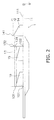
- FIG. 2 is a diagram showing a cross section at position II-II shown in FIG. 1 as seen in a predetermined direction 91.
- the heat exchanger-use fin 1 is a heat exchanger-use fin attached to heat transfer tubes and is equipped with a fin body 11, plural collars 13 and erect portions 14 and 15.
- the heat exchanger-use fin 1 is obtained by working a single sheet of heat transfer material, for example.
- the collars 13 are obtained by, for example, pressing the sheet of heat transfer material.
- the erect portions 14 and 15 are obtained by cutting and raising and working the sheet of heat transfer material
- the fin body 11 extends in the predetermined direction 91, and plural holes 12 into which the heat transfer tubes are inserted are disposed in the fin body 11.
- the plural holes 12 are disposed along the predetermined direction 91.
- the plural collars 13 are all annular and are disposed on the same side with respect to the fin body 11.
- the collars 13 are erected surrounding the holes 12 such that one collar 13 surrounds each hole 12.
- the collars 13 are all disposed in the following state. That is, the collars 13 are disposed between two straight lines 101 and 102 that extend in the predetermined direction 91 on a surface 111 of the fin body 11. Additionally, outer peripheries 131 of the collars 13 contact the straight lines 101 and 102.
- the erect portions 14 are erected on the fin body 11 on the same side as the collars 13 and are positioned outside the two straight lines 101 and 102.
- the erect portions 14 are not in positions on the straight lines 101 and 102.
- Distal ends 141 (positions r1) of the erect portions 14 are in higher positions than distal ends 132 (positions r2) of the plural collars 13 when seen from the surface 111 ( FIG. 2 ).
- the erect portions 15 are erected on the fin body 11 on the same side as the collars 13 and are positioned between the two straight lines 101 and 102.
- the erect portions 15 are not in positions on the straight lines 101 and 102.
- Distal ends 151 of the erect portions 15 are in lower positions than the distal ends 132 of the collars 13 when seen from the surface 111 ( FIG. 2 ).
- FIG. 4 is a diagram showing a cross section at position IV-IV shown in FIG. 3 as seen in the predetermined direction 91 and shows the guide 20 in a state where it is used in the heat exchanger-use fin 1.
- the guide 20 includes guide portions 201 and 202 and a connecting portion 203.
- the positions where the guide portions 201 and 202 are disposed are indicated by hatching.
- the guide portions 201 and 202 respectively extend along the straight lines 101 and 102 and slidably sandwich the plural collars 13. By sliding the collars 13 between the guides 201 and 202, the heat exchanger-use fin 1 can be moved to a predetermined position.
- the erect portions 14 and 15 are not in positions on the straight lines 101 and 102 as mentioned above, it is easy to dispose the guide portions 201 and 202 respectively on the straight lines 101 and 102.
- the connecting portion 203 interconnects the guide portions 201 and 202 on the opposite side of the fin body 11.
- the collars 13 sandwiched by the guides 201 and 202 are blocked off by the connecting portion 203 on the opposite side of the fin body 11.
- the guide portions 201 and 202 contact the surface 111 of the fin body 11 ( FIG. 4 ).
- the connecting portion 203 contacts the collars 13 ( FIG. 4 ). Thus, there are no longer gaps between the guide portions 201 and 202 and the fin body 11 and between the collars 13 and the connecting portion 203.
- a space 301 (indicated by hatching in FIG. 3 ) between the collars 13 that are mutually adjacent in the predetermined direction 91 can be placed in a substantially hermetically sealed state by the guide portions 201 and 202 and the connecting portion 203. Because the erect portions 14 are positioned outside of the two straight lines 101 and 102, the erect portions 14 do not hinder the connecting portion 203 from contacting the collars 13.
- the space 301 is placed in a substantially hermetically sealed state by the guide 20, air in the space 301 can be evacuated to lower the air pressure in the space 301.
- the heat exchanger-use fin 1 can be drawn to the guide 20 even without holding the heat exchanger-use fin 1 from the opposite side of the guide 20.
- the heat exchanger-use fin 1 is easy to handle in the manufacturing process.
- a heat exchanger can be obtained by inserting heat transfer tubes into the plural holes 12 disposed in the aforementioned heat exchanger-use fin 1.
- the distal ends 141 of the erect portions 14 are in higher positions than the distal ends 132 of the collars 13, so air flowing into the heat exchanger can be efficiently agitated. Thus, heat exchange efficiency rises.
- FIG. 6 is a diagram showing a cross section at position VI-VI shown in FIG. 5 as seen in the predetermined direction 91 and shows the guide 2 in a state where it is used in a plurality of the heat exchanger-use fins 1.
- the heat exchanger-use fins 1 all extend along the predetermined direction 91 and are respectively arranged in a direction 93.
- the guide 2 is used in these plural heat exchanger-use fins 1.
- the direction 93 is perpendicular to the predetermined direction 91 and is along the surface 111 of the fin body 11.
- the guide 2 is, as its members, equipped with a plurality of the guides 20 (hereinafter called “the guide members 20") that have been described in the first embodiment and connecting portions 204.
- the guide members 20 a plurality of the guides 20 (hereinafter called "the guide members 20") that have been described in the first embodiment and connecting portions 204.
- FIG. 5 like what is shown in FIG. 3 , the positions where the guide portions 201 and 202 of the guide 2 are disposed are indicated by hatching.
- the guide members 20 are plurally disposed along the direction 93 such that one each corresponds to each of the plural heat exchanger-use fins 1. Specifically, the plurality of collars 13 belonging to the same heat exchanger-use fins 1 are sandwiched by the guide portions 201 and 202 belonging to the same guide members 20.
- the collars 13 of one of the heat exchanger-use fins 1 slide between the guide portions 201 and 202 of one of the guide members 20 ( FIG. 5 ). Because the guide 2 is equipped with a plurality of the guide members 20, a plurality of the heat exchanger-use fins 1 can be moved in parallel to predetermined positions by the guide 2.
- first grooves 21 Spaces enclosed by the guide portions 201 and 202 and the connecting portions 203 belonging to the same guide members 20 can be understood as first grooves 21 ( FIG. 6 ) disposed in the guide 2. Because the guides 201 and 202 extend along the predetermined direction 91, the first grooves 21 can be understood as extending in the predetermined direction 91.
- a depth D1 of the first grooves 21 is substantially equivalent to a height h1 of the collars 31 when seen from the surface 111 of the fin body 11 ( FIG. 6 ).
- the spaces 301 (indicated by hatching in FIG. 5 ) between the collars that are mutually adjacent in the predetermined direction 91 can be placed in a substantially hermetically sealed state by the collars 13 and the inner walls 21a of the first grooves 21.
- the heat exchanger-use fins 1 can be pulled to the guide 2 even without holding the heat exchanger-use fins 1 from the opposite side of the guide 2.
- the heat exchanger-use fins 1 are easy to handle in the manufacturing process.
- the connecting portions 204 interconnect the guides 20 that are mutually adjacent in the direction 93. Specifically, the connecting portions 204 interconnect the connecting portions 203 of the guide members 20. The erect portions 14 fit in spaces that are enclosed by the guide members 20 that are mutually adjacent in the direction 93 and by the connecting portions 204.
- Second grooves 22 Spaces enclosed by the guide portions 201 and 202 that belong to different guide members 20 and are mutually adjacent in the direction 93 and by the connecting portions 204 can be understood as second grooves 22 ( FIG. 6 ) disposed in the guide 2. Because the guide members 20 are plurally disposed along the direction 93 and the guides 201 and 202 extend along the predetermined direction 91, the second grooves 22 can be understood as extending in the predetermined direction 91 and being disposed alternately with the first grooves 21 in the direction 93.
- the erect portions 14 fit in the spaces enclosed by the guide members 20 that are mutually adjacent in the direction 93 and by the connecting portions 204, the erect portions 14 belonging to the same heat exchanger-use fins 1 as the collars 13 that fit into the first grooves 21 can be understood as being fitted in the second grooves 22 that are adjacent to the first grooves 21.
- FIG. 6 a case is shown where a depth D2 of the second grooves 22 is larger than a height h2 of the erect portions 14 when seen from the surface 111 of the fin body 11. According to this configuration, the erect portions 14 do not contact the guide 2.
- the guide 2 When the guide 2 is removed from the heat exchanger-use fins 1 and seen, the guide 2 can be understood as follows. That is, in the guide 2, the first and second grooves 21 and 22 that extend in a certain direction are disposed alternately in a direction perpendicular to that direction.
Landscapes
- Engineering & Computer Science (AREA)
- Physics & Mathematics (AREA)
- Mechanical Engineering (AREA)
- Thermal Sciences (AREA)
- General Engineering & Computer Science (AREA)
- Geometry (AREA)
- Heat-Exchange Devices With Radiators And Conduit Assemblies (AREA)
- Cooling Or The Like Of Semiconductors Or Solid State Devices (AREA)
Abstract
Description
- The present invention relates to a heat exchanger-use fin and a guide that is used in the heat exchanger-use fin.
- Conventionally, in a heat exchanger-use fin, in order to raise the heat exchange efficiency of the heat exchanger-use fin, part of the fin is cut and raised to dispose erect portions or slits and louvers are disposed around holes into which heat transfer tubes are inserted. Further, annular collars that surround those holes are erected on the heat exchanger-use fin.
- In a conventional heat exchanger-use fin, distal ends of the erect portions have been in lower positions than distal ends of the collar. This is because, when plural heat exchanger-use fins are stacked on top of each other, the fin that has been stacked on top is supported by the collars,
- Technologies relating to the present invention are indicated below.
- Patent Document 1:
JP-ANo. S61-110889 - Patent Document 2:
JP-A No. H11-166796 - Patent Document 3:
JP-A No. 2001-227890 - However, even when the erect portions are disposed on the heat exchanger-use fin, heat exchange efficiency cannot be raised that much unless only erect portions that are low in terms of their relationship with the collars can be disposed.
- The present invention has been made in view of the aforementioned circumstances, and it is an object thereof to raise heat exchange efficiency.
- A heat exchanger-use fin pertaining to a first aspect of the invention is a fin attached to heat transfer tubes and is equipped with a fin body, a plurality of collars and erect portions. The fin body extends in a predetermined direction, and plural holes into which the heat transfer tubes are inserted are disposed in the fin body along the predetermined direction. The collars are erected surrounding the holes, such that one collar surrounds each hole, on the same side with respect to the fin body. When the fin is seen from the collars side, the collars are all disposed between two straight lines that extend along the predetermined direction on a surface of the fin body, and outer peripheries of the collars contact the two straight lines. The erect portions are erected on the fin body on the same side as the collars and are positioned outside the two straight lines. Distal ends of the erect portions are in higher positions than distal ends of the collars when seen from the surface.
- A heat exchanger pertaining to a second aspect of the invention comprises: the heat exchanger-use fm according to the first aspect of the invention; and heat transfer tubes that are inserted into the holes disposed in the heat exchanger-use fin.
- A guide pertaining to a third aspect of the invention is a guide that is used in the heat exchanger-use fin pertaining to the first aspect of the invention, wherein first and second grooves that extend in a certain direction are disposed. The first and second grooves are disposed alternately in a direction perpendicular to that direction. The second grooves are deeper than the first grooves.
- A guide pertaining to a fourth aspect of the invention is the guide pertaining to the third aspect of the invention, wherein a depth of the first grooves is substantially equivalent to a height of the collars when seen from the surface of the fin body.
- A guide pertaining to a fifth aspect of the invention is the guide pertaining to the third or fourth aspect of the invention, wherein a depth of the second grooves is larger than a height of the erect portions when seen from the surface of the fin body.
- A guide use method pertaining to a sixth aspect of the invention is a method of using the guide pertaining to any one of the third to fifth aspects of the invention. The guide use method comprises: slidably fitting the plurality of collars belonging to the same heat exchanger-use fin into one of the first grooves in the guide; and fitting, into the second groove that is adjacent to the first groove, the erect portions belonging to the same heat exchanger-use fin as the collars that fit into that first groove.
- A guide use method pertaining to a seventh aspect of the invention is the method pertaining to the sixth aspect of the invention, further comprising evacuating air in a space that is enclosed by the collars that belong to the same heat exchanger-use fin and are mutually adjacent in a predetermined direction and by an inner wall of the first groove.
- According to the heat exchanger-use fin pertaining to the first aspect of the invention, the distal ends of the erect portions are in higher positions than the distal ends of the collars, so in a heat exchanger obtained by attaching that heat exchanger-use fin to heat transfer tubes, air flowing into that heat exchanger can be efficiently agitated. Thus, heat exchange efficiency rises.
- Moreover, because the plurality of collars are slidably sandwiched by guides that extend on the two straight lines, the heat exchanger-use fin can be moved to a predetermined position. Moreover, because the erect portions are positioned outside those two straight lines, it is easy for the space between the collars that are mutually adjacent in the predetermined direction to be placed in a substantially hermetically sealed state by the two guides that sandwich the collars.
- According to the heat exchanger pertaining to the second aspect of the invention, air flowing into the heat exchanger can be efficiently agitated, so heat exchange efficiency is high.
- According to the guide pertaining to the third aspect of the invention, the guide can be used in a heat exchanger-use fin that is equipped with the erect portions where the positions of its distal ends are higher than the positions of the distal ends of the collars.
- According to the guide pertaining to the fourth aspect of the invention, when the plurality of collars belonging to the same heat exchanger-use fin are fitted into one of the first grooves, the space between the collars that are mutually adjacent in the predetermined direction can be placed in a substantially hermetically sealed state by those collars and an inner wall of the first groove. By lowering the air pressure in this space, the heat exchanger-use fin can be drawn to the guide even without holding the heat exchanger-use fin from the opposite side of the guide. Thus, the heat exchanger-use fin is easy to handle in the manufacturing process.
- According to the guide pertaining to the fifth aspect of the invention, the erect portions can be prevented from contacting the guide when the erect portions are fitted in the second grooves.
- According to the guide use method pertaining to the sixth aspect of the invention, by fitting and sliding the plurality of collars belonging to the same heat exchanger-use fin in one of the first grooves, that heat exchanger-use fin can be moved to a predetermined position. Because the first grooves are plurally disposed in the guide, plural heat exchanger-use fins can be moved in parallel to predetermined positions. Moreover, because the erect portions fit in the second grooves, it is difficult for the movement of the heat exchanger-use fins to be hindered by the erect portions.
- According to the guide use method pertaining to the seventh aspect of the invention, the air pressure in the space can be lowered by evacuating the air in that space. Thus, the heat exchanger-use fin is drawn to the guides.
-
-
FIG. 1 is a diagram conceptually showing a heat exchanger-use fin pertaining to a first embodiment. -
FIG. 2 is a diagram showing a cross section at position II-II shown inFIG. 1 as seen in apredetermined direction 91. -
FIG. 3 is a diagram used in the description of aguide 20. -
FIG. 4 is a diagram showing a cross section at position IV-IV shown inFIG. 3 as seen in thepredetermined direction 91. -
FIG. 5 is a diagram used in the description of aguide 2 pertaining to a second embodiment. -
FIG. 6 is a diagram showing a cross section at position VI-VI shown inFIG. 5 as seen in thepredetermined direction 91. -
- 1
- Heat Exchanger-Use Fin
- 2
- Guide
- 11
- Fin Body
- 12
- Holes
- 13
- Collars
- 14
- Erect Portions
- 21
- First Grooves
- 21 a
- Inner Walls
- 22
- Second Grooves
- 91
- Predetermined Direction
- 101,102
- Straight Lines
- 111
- Surface
- 131
- Outer Peripheries
- 132, 141
- Distal Ends
- 301
- Spaces
- D1,D2
- Depths
- h1, h2
- Heights
-
FIG. 1 is a diagram conceptually showing a heat exchanger-use fin 1 pertaining to the present embodiment.FIG. 2 is a diagram showing a cross section at position II-II shown inFIG. 1 as seen in apredetermined direction 91. - The heat exchanger-
use fin 1 is a heat exchanger-use fin attached to heat transfer tubes and is equipped with afin body 11,plural collars 13 anderect portions - The heat exchanger-
use fin 1 is obtained by working a single sheet of heat transfer material, for example. Specifically, thecollars 13 are obtained by, for example, pressing the sheet of heat transfer material. Theerect portions - The
fin body 11 extends in thepredetermined direction 91, andplural holes 12 into which the heat transfer tubes are inserted are disposed in thefin body 11. The plural holes 12 are disposed along thepredetermined direction 91. - The
plural collars 13 are all annular and are disposed on the same side with respect to thefin body 11. Thecollars 13 are erected surrounding theholes 12 such that onecollar 13 surrounds eachhole 12. - When the heat exchanger-
use fin 1 is seen from thecollars 13 side, thecollars 13 are all disposed in the following state. That is, thecollars 13 are disposed between twostraight lines predetermined direction 91 on asurface 111 of thefin body 11. Additionally,outer peripheries 131 of thecollars 13 contact thestraight lines - The
erect portions 14 are erected on thefin body 11 on the same side as thecollars 13 and are positioned outside the twostraight lines erect portions 14 are not in positions on thestraight lines erect portions 14 are in higher positions than distal ends 132 (positions r2) of theplural collars 13 when seen from the surface 111 (FIG. 2 ). - The
erect portions 15 are erected on thefin body 11 on the same side as thecollars 13 and are positioned between the twostraight lines erect portions 15 are not in positions on thestraight lines erect portions 15 are in lower positions than the distal ends 132 of thecollars 13 when seen from the surface 111 (FIG. 2 ). - A
guide 20 that is used in the heat exchanger-use fin 1 will be described usingFIG. 3 andFIG. 4. FIG. 4 is a diagram showing a cross section at position IV-IV shown inFIG. 3 as seen in thepredetermined direction 91 and shows theguide 20 in a state where it is used in the heat exchanger-use fin 1. - The
guide 20 includesguide portions portion 203. InFIG. 3 , the positions where theguide portions guide portions straight lines plural collars 13. By sliding thecollars 13 between theguides use fin 1 can be moved to a predetermined position. - Because the
erect portions straight lines guide portions straight lines - The connecting
portion 203 interconnects theguide portions fin body 11. Thecollars 13 sandwiched by theguides portion 203 on the opposite side of thefin body 11. - The
guide portions surface 111 of the fin body 11 (FIG. 4 ). The connectingportion 203 contacts the collars 13 (FIG. 4 ). Thus, there are no longer gaps between theguide portions fin body 11 and between thecollars 13 and the connectingportion 203. - Thus, a space 301 (indicated by hatching in
FIG. 3 ) between thecollars 13 that are mutually adjacent in thepredetermined direction 91 can be placed in a substantially hermetically sealed state by theguide portions portion 203. Because theerect portions 14 are positioned outside of the twostraight lines erect portions 14 do not hinder the connectingportion 203 from contacting thecollars 13. - Because the
space 301 is placed in a substantially hermetically sealed state by theguide 20, air in thespace 301 can be evacuated to lower the air pressure in thespace 301. Thus, the heat exchanger-use fin 1 can be drawn to theguide 20 even without holding the heat exchanger-use fin 1 from the opposite side of theguide 20. Thus, the heat exchanger-use fin 1 is easy to handle in the manufacturing process. - A heat exchanger can be obtained by inserting heat transfer tubes into the
plural holes 12 disposed in the aforementioned heat exchanger-use fin 1. - According to the aforementioned heat exchanger-
use fin 1, the distal ends 141 of theerect portions 14 are in higher positions than the distal ends 132 of thecollars 13, so air flowing into the heat exchanger can be efficiently agitated. Thus, heat exchange efficiency rises. - In the present embodiment, a
guide 2 that is used in the heat exchanger-use fin 1 that has been described in the first embodiment will be described usingFIG. 5 andFIG. 6. FIG. 6 is a diagram showing a cross section at position VI-VI shown inFIG. 5 as seen in thepredetermined direction 91 and shows theguide 2 in a state where it is used in a plurality of the heat exchanger-use fins 1. - The heat exchanger-
use fins 1 all extend along thepredetermined direction 91 and are respectively arranged in adirection 93. Theguide 2 is used in these plural heat exchanger-use fins 1. Here, thedirection 93 is perpendicular to thepredetermined direction 91 and is along thesurface 111 of thefin body 11. - The
guide 2 is, as its members, equipped with a plurality of the guides 20 (hereinafter called "theguide members 20") that have been described in the first embodiment and connectingportions 204. InFIG. 5 , like what is shown inFIG. 3 , the positions where theguide portions guide 2 are disposed are indicated by hatching. - The
guide members 20 are plurally disposed along thedirection 93 such that one each corresponds to each of the plural heat exchanger-use fins 1. Specifically, the plurality ofcollars 13 belonging to the same heat exchanger-use fins 1 are sandwiched by theguide portions same guide members 20. - Thus, the
collars 13 of one of the heat exchanger-use fins 1 slide between theguide portions FIG. 5 ). Because theguide 2 is equipped with a plurality of theguide members 20, a plurality of the heat exchanger-use fins 1 can be moved in parallel to predetermined positions by theguide 2. - Spaces enclosed by the
guide portions portions 203 belonging to thesame guide members 20 can be understood as first grooves 21 (FIG. 6 ) disposed in theguide 2. Because theguides predetermined direction 91, thefirst grooves 21 can be understood as extending in thepredetermined direction 91. - Additionally, in view of the fact that the plurality of
collars 13 belonging to the same heat exchanger-use fin 1 are sandwiched by and slide between theguide portions same guide member 20, it can be understood that the plurality ofcollars 13 belonging to the same heat exchanger-use fin 1 are slidably fitted into one of thefirst grooves 21. - A depth D1 of the
first grooves 21 is substantially equivalent to a height h1 of the collars 31 when seen from thesurface 111 of the fin body 11 (FIG. 6 ). Thus, when the plurality ofcollars 13 belonging to the same heat exchanger-use fin 1 are fitted into one of thefirst grooves 21, it is difficult for a gap to form between the distal ends 132 of thecollars 13 and aninner wall 21 a of thefirst groove 21. - Thus, the spaces 301 (indicated by hatching in
FIG. 5 ) between the collars that are mutually adjacent in thepredetermined direction 91 can be placed in a substantially hermetically sealed state by thecollars 13 and theinner walls 21a of thefirst grooves 21. - By placing the
spaces 301 in a substantially hermetically sealed state, for example, air in thespaces 301 can be evacuated to lower the air pressure in thespaces 301. Thus, the heat exchanger-use fins 1 can be pulled to theguide 2 even without holding the heat exchanger-use fins 1 from the opposite side of theguide 2. Thus, the heat exchanger-use fins 1 are easy to handle in the manufacturing process. - The connecting
portions 204 interconnect theguides 20 that are mutually adjacent in thedirection 93. Specifically, the connectingportions 204 interconnect the connectingportions 203 of theguide members 20. Theerect portions 14 fit in spaces that are enclosed by theguide members 20 that are mutually adjacent in thedirection 93 and by the connectingportions 204. - Spaces enclosed by the
guide portions different guide members 20 and are mutually adjacent in thedirection 93 and by the connectingportions 204 can be understood as second grooves 22 (FIG. 6 ) disposed in theguide 2. Because theguide members 20 are plurally disposed along thedirection 93 and theguides predetermined direction 91, thesecond grooves 22 can be understood as extending in thepredetermined direction 91 and being disposed alternately with thefirst grooves 21 in thedirection 93. - Additionally, in view of the fact that the
erect portions 14 fit in the spaces enclosed by theguide members 20 that are mutually adjacent in thedirection 93 and by the connectingportions 204, theerect portions 14 belonging to the same heat exchanger-use fins 1 as thecollars 13 that fit into thefirst grooves 21 can be understood as being fitted in thesecond grooves 22 that are adjacent to thefirst grooves 21. -
Surfaces 204a of the connectingportions 204 on thefin body 11 side are further withdrawn toward the opposite side of thefin body 11 thansurfaces 203a of the connectingportions 203 on thefin body 11 side (FIG. 6 ). To describe this using the first andsecond grooves second grooves 22 are deeper than thefirst grooves 21. According to this aspect, it is difficult for the distal ends 141 of theerect portions 14 to contact thesurfaces 204a of the connectingportions 204. - In
FIG. 6 , a case is shown where a depth D2 of thesecond grooves 22 is larger than a height h2 of theerect portions 14 when seen from thesurface 111 of thefin body 11. According to this configuration, theerect portions 14 do not contact theguide 2. - When the
guide 2 is removed from the heat exchanger-use fins 1 and seen, theguide 2 can be understood as follows. That is, in theguide 2, the first andsecond grooves
Claims (7)
- A heat exchanger-use fin (1) that is attached to heat transfer tubes, the heat exchanger-use fin comprising:a fin body (11) that extends in a predetermine direction (91) and in which plural holes (12) into which the heat transfer tubes are inserted are disposed along the predetermined direction;a plurality of annular collars (13) that are erected surrounding the holes, such that one collar surrounds each hole, on the same side with respect to the fin body; anderect portions (14) that are erected on the fin body on the same side as the collars, wherein
when the fin is seen from the collars side, the collars are all disposed between two straight lines (101, 102) that extend along the predetermined direction on a surface (111) of the fin body, with outer peripheries (131) of the collars contacting the two straight lines,the erect portions are positioned outside the two straight lines, anddistal ends (141) of the erect portions are in higher positions than distal ends (132) of the collars when seen from the surface. - A heat exchanger comprising:the heat exchanger-use fin (1) according to claim 1; andheat transfer tubes that are inserted into the holes (12) disposed in the heat exchanger-use fin.
- A guide (2) that is used in the heat exchanger-use fin (1) according to claim 1, wherein first and second grooves (21, 22) that extend in a certain direction are disposed alternately in a direction perpendicular to that direction, and the second grooves (22) are deeper than the first grooves (21).
- The guide according to claim 3, wherein a depth (D1) of the first grooves (21) is substantially equivalent to a height (h1) of the collars (13) when seen from the surface (111) of the fin body (11).
- The guide according to claim 3 or claim 4, wherein a depth (D2) of the second grooves (22) is larger than a height (h2) of the erect portions (14) when seen from the surface (111) of the fin body (11).
- A method of using the guide (2) according to any one of claim 3 to claim 5, the method comprising:slidably fitting the plurality of collars (13) belonging to the same heat exchanger-use fin (1) into one of the first grooves (21) in the guide; andfitting, into the second groove (22) that is adjacent to the first groove, the erect portions (14) belonging to the same heat exchanger-use fin as the collars that fit into that first groove.
- The guide use method according to claim 6, further comprising evacuating air in a space (301) that is enclosed by the collars (13) that belong to the same heat exchanger-use fm (1) and are mutually adjacent in a predetermined direction (91) and by an inner wall (21a) of the first groove (21).
Applications Claiming Priority (2)
| Application Number | Priority Date | Filing Date | Title |
|---|---|---|---|
| JP2007070337A JP4293252B2 (en) | 2007-03-19 | 2007-03-19 | Fin for heat exchanger, guide and method of using the same |
| PCT/JP2008/054884 WO2008114775A1 (en) | 2007-03-19 | 2008-03-17 | Fin for heat exchanger, guide, and method of using the guide |
Publications (2)
| Publication Number | Publication Date |
|---|---|
| EP2141434A1 true EP2141434A1 (en) | 2010-01-06 |
| EP2141434A4 EP2141434A4 (en) | 2014-06-11 |
Family
ID=39765882
Family Applications (1)
| Application Number | Title | Priority Date | Filing Date |
|---|---|---|---|
| EP08722279.0A Withdrawn EP2141434A4 (en) | 2007-03-19 | 2008-03-17 | THERMAL EXCHANGER FIN, GUIDE AND METHOD OF USING THE GUIDE |
Country Status (7)
| Country | Link |
|---|---|
| US (1) | US20100018691A1 (en) |
| EP (1) | EP2141434A4 (en) |
| JP (1) | JP4293252B2 (en) |
| KR (1) | KR20090127343A (en) |
| CN (1) | CN101636631A (en) |
| AU (1) | AU2008227549B2 (en) |
| WO (1) | WO2008114775A1 (en) |
Cited By (1)
| Publication number | Priority date | Publication date | Assignee | Title |
|---|---|---|---|---|
| EP3062053A1 (en) * | 2015-02-24 | 2016-08-31 | Heatcraft Refrigeration Products LLC | Heat exchanger with louvered fins |
Families Citing this family (8)
| Publication number | Priority date | Publication date | Assignee | Title |
|---|---|---|---|---|
| CN102356014B (en) * | 2009-03-24 | 2013-06-19 | 住友精密工业株式会社 | Heat sink |
| JP5385062B2 (en) * | 2009-09-08 | 2014-01-08 | リンナイ株式会社 | Hot air heater |
| US9151546B2 (en) | 2013-02-28 | 2015-10-06 | General Electric Company | Heat exchanger assembly |
| EP3321624B1 (en) * | 2015-07-10 | 2021-04-14 | Mitsubishi Electric Corporation | THERMAL EXCHANGER AND AIR CONDITIONING DEVICE |
| WO2017179399A1 (en) * | 2016-04-15 | 2017-10-19 | 三菱電機株式会社 | Heat exchanger |
| WO2019062493A1 (en) * | 2017-09-30 | 2019-04-04 | 杭州三花微通道换热器有限公司 | Heat exchanger and fin |
| CN112570588B (en) * | 2019-09-27 | 2024-06-04 | 广东美的智能机器人有限公司 | Guide mechanism and assembly system |
| WO2022045667A1 (en) * | 2020-08-31 | 2022-03-03 | Samsung Electronics Co., Ltd. | Heat exchanger and air conditioner using the heat exchanger |
Family Cites Families (16)
| Publication number | Priority date | Publication date | Assignee | Title |
|---|---|---|---|---|
| JPS61110889A (en) | 1984-11-05 | 1986-05-29 | Matsushita Electric Ind Co Ltd | Finned heat exchanger |
| US4698904A (en) * | 1985-09-13 | 1987-10-13 | Hitachi, Ltd. | Apparatus for assembling fins and tubes for heat exchangers |
| JPH0771890A (en) * | 1993-09-03 | 1995-03-17 | Oak Japan:Kk | Heat exchanger |
| KR960031954A (en) * | 1995-02-20 | 1996-09-17 | 구자홍 | Fin of heat exchanger |
| US5819394A (en) * | 1995-02-22 | 1998-10-13 | Transition Automation, Inc. | Method of making board matched nested support fixture |
| KR0133026Y1 (en) * | 1995-07-13 | 1999-01-15 | 김광호 | Heat exchanger of air conditioner |
| JP3264156B2 (en) * | 1995-12-01 | 2002-03-11 | 株式会社日立製作所 | Heat transfer fins |
| JP3367353B2 (en) * | 1996-11-12 | 2003-01-14 | 松下電器産業株式会社 | Finned heat exchanger |
| JP3430921B2 (en) | 1997-10-03 | 2003-07-28 | 株式会社日立製作所 | Heat exchanger |
| JPH11281279A (en) * | 1998-03-26 | 1999-10-15 | Sharp Corp | Heat exchanger |
| JP2001227890A (en) | 2000-02-15 | 2001-08-24 | Hitachi Ltd | Heat exchanger |
| WO2003025491A1 (en) * | 2001-09-21 | 2003-03-27 | E.I. Du Pont De Nemours And Company | Heat exchanger fabrication by polymer extrusion and structures formed thereby |
| US7021370B2 (en) * | 2003-07-24 | 2006-04-04 | Delphi Technologies, Inc. | Fin-and-tube type heat exchanger |
| JP2007010279A (en) * | 2005-07-01 | 2007-01-18 | Daikin Ind Ltd | Finned tube heat exchanger |
| US7507002B2 (en) * | 2005-07-01 | 2009-03-24 | Hewlett Packard Development Company, L.P. | Reflector with de-coupling interface layer |
| US7510280B2 (en) * | 2005-08-30 | 2009-03-31 | Real D | High yield bonding process for manufacturing polycarbonate polarized lenses |
-
2007
- 2007-03-19 JP JP2007070337A patent/JP4293252B2/en not_active Expired - Fee Related
-
2008
- 2008-03-17 US US12/529,629 patent/US20100018691A1/en not_active Abandoned
- 2008-03-17 EP EP08722279.0A patent/EP2141434A4/en not_active Withdrawn
- 2008-03-17 WO PCT/JP2008/054884 patent/WO2008114775A1/en not_active Ceased
- 2008-03-17 AU AU2008227549A patent/AU2008227549B2/en not_active Ceased
- 2008-03-17 CN CN200880008612A patent/CN101636631A/en active Pending
- 2008-03-17 KR KR1020097020858A patent/KR20090127343A/en not_active Ceased
Cited By (3)
| Publication number | Priority date | Publication date | Assignee | Title |
|---|---|---|---|---|
| EP3062053A1 (en) * | 2015-02-24 | 2016-08-31 | Heatcraft Refrigeration Products LLC | Heat exchanger with louvered fins |
| US10209012B2 (en) | 2015-02-24 | 2019-02-19 | Lgl France | Heat exchanger with louvered fins |
| US11162741B2 (en) | 2015-02-24 | 2021-11-02 | Lgl France | Heat exchanger with louvered fins |
Also Published As
| Publication number | Publication date |
|---|---|
| AU2008227549A1 (en) | 2008-09-25 |
| AU2008227549B2 (en) | 2010-11-18 |
| EP2141434A4 (en) | 2014-06-11 |
| JP2008232497A (en) | 2008-10-02 |
| US20100018691A1 (en) | 2010-01-28 |
| JP4293252B2 (en) | 2009-07-08 |
| CN101636631A (en) | 2010-01-27 |
| WO2008114775A1 (en) | 2008-09-25 |
| KR20090127343A (en) | 2009-12-10 |
Similar Documents
| Publication | Publication Date | Title |
|---|---|---|
| US20100018691A1 (en) | Fin for heat exchanger, guide, and method of using the guide | |
| US5582246A (en) | Finned tube heat exchanger with secondary star fins and method for its production | |
| EP1221754A2 (en) | Generator stator cooling design with concavity surfaces | |
| BRPI0920049B1 (en) | Fin heat exchanger and heat exchanger | |
| CN214950816U (en) | Heat exchanger fin | |
| KR102402099B1 (en) | Mold device of condenser pipe for vehicle | |
| JPWO2016203593A1 (en) | Flat tube insertion device for heat exchanger fins | |
| US20030094273A1 (en) | Corrugated fin assembly | |
| CN107206555A (en) | The withdrawing device of flat tube fin | |
| JP4811087B2 (en) | Heat exchanger | |
| EP1795853B1 (en) | A heat exchanger and a method of manufacturing the same. | |
| JP2005337606A (en) | Stacked heat exchanger and its manufacturing method | |
| EP1445569A3 (en) | Heat exchanger | |
| KR101218314B1 (en) | Micro Channel Plate for Heat Exchanger | |
| US20120132410A1 (en) | Heat sink fin forming process | |
| JPH06159985A (en) | Heat exchanger and its preparation | |
| JP5661578B2 (en) | Manufacturing method of heat exchanger | |
| KR20180008794A (en) | Collecting plates for heat exchangers, especially for automobiles | |
| KR100638285B1 (en) | Tube insertion hole processing method of header pipe for heat exchanger | |
| EP1712865A1 (en) | Corrugate fin for integrally assembled heat exchangers | |
| JP2001116484A (en) | Heat exchanger | |
| KR102907653B1 (en) | Mold device for header plate for automobile air conditioner | |
| KR100241875B1 (en) | Snap ring manufacturing method | |
| EP2509094B1 (en) | Magnetron and apparatus that uses microwaves | |
| CN223222283U (en) | Stamping die |
Legal Events
| Date | Code | Title | Description |
|---|---|---|---|
| PUAI | Public reference made under article 153(3) epc to a published international application that has entered the european phase |
Free format text: ORIGINAL CODE: 0009012 |
|
| 17P | Request for examination filed |
Effective date: 20091015 |
|
| AK | Designated contracting states |
Kind code of ref document: A1 Designated state(s): AT BE BG CH CY CZ DE DK EE ES FI FR GB GR HR HU IE IS IT LI LT LU LV MC MT NL NO PL PT RO SE SI SK TR |
|
| DAX | Request for extension of the european patent (deleted) | ||
| A4 | Supplementary search report drawn up and despatched |
Effective date: 20140514 |
|
| RIC1 | Information provided on ipc code assigned before grant |
Ipc: F28F 1/32 20060101AFI20140508BHEP Ipc: F28F 13/06 20060101ALI20140508BHEP Ipc: B21D 53/08 20060101ALI20140508BHEP |
|
| STAA | Information on the status of an ep patent application or granted ep patent |
Free format text: STATUS: THE APPLICATION IS DEEMED TO BE WITHDRAWN |
|
| 18D | Application deemed to be withdrawn |
Effective date: 20141213 |