EP2141433A2 - Hot water stratification buffer storage - Google Patents
Hot water stratification buffer storage Download PDFInfo
- Publication number
- EP2141433A2 EP2141433A2 EP09008021A EP09008021A EP2141433A2 EP 2141433 A2 EP2141433 A2 EP 2141433A2 EP 09008021 A EP09008021 A EP 09008021A EP 09008021 A EP09008021 A EP 09008021A EP 2141433 A2 EP2141433 A2 EP 2141433A2
- Authority
- EP
- European Patent Office
- Prior art keywords
- fluid line
- thermally insulated
- buffer store
- zones
- water
- Prior art date
- Legal status (The legal status is an assumption and is not a legal conclusion. Google has not performed a legal analysis and makes no representation as to the accuracy of the status listed.)
- Granted
Links
Images
Classifications
-
- F—MECHANICAL ENGINEERING; LIGHTING; HEATING; WEAPONS; BLASTING
- F28—HEAT EXCHANGE IN GENERAL
- F28D—HEAT-EXCHANGE APPARATUS, NOT PROVIDED FOR IN ANOTHER SUBCLASS, IN WHICH THE HEAT-EXCHANGE MEDIA DO NOT COME INTO DIRECT CONTACT
- F28D20/00—Heat storage plants or apparatus in general; Regenerative heat-exchange apparatus not covered by groups F28D17/00 or F28D19/00
- F28D20/0034—Heat storage plants or apparatus in general; Regenerative heat-exchange apparatus not covered by groups F28D17/00 or F28D19/00 using liquid heat storage material
- F28D20/0039—Heat storage plants or apparatus in general; Regenerative heat-exchange apparatus not covered by groups F28D17/00 or F28D19/00 using liquid heat storage material with stratification of the heat storage material
-
- F—MECHANICAL ENGINEERING; LIGHTING; HEATING; WEAPONS; BLASTING
- F24—HEATING; RANGES; VENTILATING
- F24H—FLUID HEATERS, e.g. WATER OR AIR HEATERS, HAVING HEAT-GENERATING MEANS, e.g. HEAT PUMPS, IN GENERAL
- F24H9/00—Details
- F24H9/12—Arrangements for connecting heaters to circulation pipes
- F24H9/13—Arrangements for connecting heaters to circulation pipes for water heaters
- F24H9/133—Storage heaters
-
- F—MECHANICAL ENGINEERING; LIGHTING; HEATING; WEAPONS; BLASTING
- F28—HEAT EXCHANGE IN GENERAL
- F28D—HEAT-EXCHANGE APPARATUS, NOT PROVIDED FOR IN ANOTHER SUBCLASS, IN WHICH THE HEAT-EXCHANGE MEDIA DO NOT COME INTO DIRECT CONTACT
- F28D20/00—Heat storage plants or apparatus in general; Regenerative heat-exchange apparatus not covered by groups F28D17/00 or F28D19/00
- F28D2020/0065—Details, e.g. particular heat storage tanks, auxiliary members within tanks
- F28D2020/0069—Distributing arrangements; Fluid deflecting means
-
- F—MECHANICAL ENGINEERING; LIGHTING; HEATING; WEAPONS; BLASTING
- F28—HEAT EXCHANGE IN GENERAL
- F28F—DETAILS OF HEAT-EXCHANGE AND HEAT-TRANSFER APPARATUS, OF GENERAL APPLICATION
- F28F2270/00—Thermal insulation; Thermal decoupling
-
- Y—GENERAL TAGGING OF NEW TECHNOLOGICAL DEVELOPMENTS; GENERAL TAGGING OF CROSS-SECTIONAL TECHNOLOGIES SPANNING OVER SEVERAL SECTIONS OF THE IPC; TECHNICAL SUBJECTS COVERED BY FORMER USPC CROSS-REFERENCE ART COLLECTIONS [XRACs] AND DIGESTS
- Y02—TECHNOLOGIES OR APPLICATIONS FOR MITIGATION OR ADAPTATION AGAINST CLIMATE CHANGE
- Y02E—REDUCTION OF GREENHOUSE GAS [GHG] EMISSIONS, RELATED TO ENERGY GENERATION, TRANSMISSION OR DISTRIBUTION
- Y02E60/00—Enabling technologies; Technologies with a potential or indirect contribution to GHG emissions mitigation
- Y02E60/14—Thermal energy storage
Definitions
- the invention relates to a buffer memory with several zones for storing water of different temperature.
- a buffer memory of the generic type is used to store water in the context of a heating system and / or a hot water supply.
- the buffer memory is used to compensate for differences between the amount of heat generated and consumed and compensate for example, power fluctuations of an upstream solar system and / or heat pump.
- hot water can be stored, for example, from a solar system in high-performance times and be taken off again in periods of reduced performance. This allows the generation of heat to a certain extent, regardless of consumption. Overall, the efficiency of a heating and / or hot water system is improved in this way.
- the housing of buffer tanks is regularly thermally insulated.
- water-carrying lines for loading and unloading the various temperature zones can pass through two or more zones of the buffer within the buffer memory.
- the invention has for its object to improve the efficiency of a buffer memory.
- a temperature loss of 18 ° C At a water inlet temperature of about 50 ° C in the steel water pipe and a flow rate of 0.3 l / min resulted in a temperature of the ambient water of 18 ° C over a distance of 1.2 meters, a temperature loss of 18 ° C.
- the temperature of the water inside the pipeline may, if necessary, be reduced to such an extent that the water fed into a zone via this pipeline is colder than the ambient temperature of the zone. Instead of heating up the water of this zone via hot water supply, it would even be cooled. Conversely, passing through the pipeline through a zone hot water, the water in this zone also undesirable heat.
- the invention provides in its most general embodiment, a buffer memory, which is formed with zones for storing water of different temperature, wherein at least one fluid line is guided through at least two zones of the buffer memory and thermally insulated.
- thermal insulation of running within the buffer fluid line heat loss can be drastically reduced and thus the efficiency of the buffer memory can be increased dramatically.
- the thermal energy of the fluid usually water, but also gas, now predominantly reaches where it is needed.
- a fluid line of the type mentioned consists of steel.
- Such a fluid line can now be thermally insulated on the inside and / or outside.
- Suitable insulating materials are, for example: EPDM (ethylene-propylene-diene rubber), SBR (styrene-butadiene copolymer), chloroprene rubber, or in general, any insulating material which is water-resistant, with closed-cell and flexible insulating material free of fluorocarbons ( CFC) is preferred.
- EPDM ethylene-propylene-diene rubber
- SBR styrene-butadiene copolymer
- chloroprene rubber or in general, any insulating material which is water-resistant, with closed-cell and flexible insulating material free of fluorocarbons ( CFC) is preferred.
- foamed plastic materials such as foam polystyrene or other types of rubber.
- the insulation can be applied to the tubular body as a monolithic mass.
- the insulation can also consist of a prefabricated molded part. For example, a corresponding insulating tube is shrunk on the outside of the water line, mounted and / or glued. Analogously, this can be done inside.
- thermally insulating material which has in particular the following thermal insulation properties with usual wall thickness (0.5 - 5 cm):
- the material should be selected so that at a flow rate between 0.1 and 5 l / min through the water pipe and a total length of the thermally insulated water pipe in the buffer between 1 and 2 m at a temperature difference to the ambient temperature of 30 ° C, a temperature loss of maximum 5 ° C, maximum 4 ° C or better at most 2 ° C results.
- EPDM with the appropriate material thickness can fulfill this criterion for the insulating material.
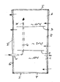
- FIGURE shows, schematically, in a longitudinal section an externally thermally insulated (insulation I) buffer memory with three zones A, B, C, wherein in the lowermost zone C a temperature of assumed about 18 ° C, in the zone B a Temperature of assumed about 30 ° C and in the uppermost zone A an average temperature of about 60 ° C prevails.
- insulation I externally thermally insulated
- the zones A, B are separated by a laminar sheet D and the zones B, C are separated by a laminar sheet E, the laminations D, E being substantially parallel to the bottom F of the substantially barrel-like (cylindrical) buffer but spaced apart Wall G, to allow a transition of water from one zone to an adjacent zone.
- a water pipe W passes through the layer sheet D, the zone B into the zone C and from there out of the buffer memory.
- the water pipe has an outer diameter of about 27 mm, an inner diameter of about 19 mm (3/4 "), a wall thickness of about 4 mm, on the inside on a 2 mm thick base body made of steel mm thick hose made of EPDM is glued as insulation.
- the water supplied at about 70 ° C in the water pipe W is fed in an amount of 0.5 l / min in the zone C, passes through the zone C partially and the zone B completely and occurs in the zone A above the layer sheet D. with about 66 ° C off.
- the heat loss is therefore only 4 ° C.
- the insulation on the inside of the fluid line / water line has the advantage that no special requirements for tightness must be made to the fluid line. This task can take over the inner insulation.
- the fluid line (W) can be correspondingly formed on the inside for thermal insulation at least in sections with an insulating tube.
- the fluid line may have openings on the wall side, wherein the outflow region is then defined by the course of the inside insulation.
- the fluid line can be made, for example, from a perforated plate.
- the inner insulation for example via an insulating hose, has the further advantage that the insulation can also be retrofitted. This makes it possible to retrofit existing systems. Similarly, an exchange / repair can be done from the outside, without having to dismantle the buffer memory.
- the insulating tube or a corresponding inside insulating layer is held by friction on the inner wall of the fluid line. But it can also be done an additional bond or other attachment.
Abstract
Description
Die Erfindung betrifft einen Pufferspeicher mit mehreren Zonen zur Speicherung von Wasser unterschiedlicher Temperatur.The invention relates to a buffer memory with several zones for storing water of different temperature.
Ein Pufferspeicher der gattungsgemäßen Art dient der Speicherung von Wasser im Rahmen einer Heizungsanlage und/oder einer Warmwasserversorgung.A buffer memory of the generic type is used to store water in the context of a heating system and / or a hot water supply.
Der Pufferspeicher dient dazu, Differenzen zwischen erzeugter und verbrauchter Wärmemenge auszugleichen und beispielsweise Leistungsschwankungen einer vorgeschalteten Solaranlage und/oder Wärmepumpe zu kompensieren.The buffer memory is used to compensate for differences between the amount of heat generated and consumed and compensate for example, power fluctuations of an upstream solar system and / or heat pump.
Mit Hilfe des Pufferspeichers kann Warmwasser zum Beispiel aus einer Solaranlage in leistungsstarken Zeiten gespeichert und in leistungsärmeren Zeiten wieder abgenommen werden. Damit lässt sich die Wärmeerzeugung in gewissem Umfang unabhängig vom Verbrauch betreiben. Insgesamt wird auf diese Weise der Wirkungsgrad einer Heizungs- und/oder Warmwasseranlage verbessert.With the help of the buffer tank hot water can be stored, for example, from a solar system in high-performance times and be taken off again in periods of reduced performance. This allows the generation of heat to a certain extent, regardless of consumption. Overall, the efficiency of a heating and / or hot water system is improved in this way.
Zur Reduzierung von Wärmeverlusten ist das Gehäuse von Pufferspeichern regelmäßig thermisch isoliert.To reduce heat loss, the housing of buffer tanks is regularly thermally insulated.
Es ist ebenso bekannt, einen Pufferspeicher in verschiedene Zonen zu unterteilen, um eine gewisse Temperaturschichtung zu erreichen, das heißt, in Vertikalrichtung Zonen mit Wasser unterschiedlicher Temperatur ausbilden zu können. Dabei werden die Zonen durch so genannte Schichtenbleche voneinander getrennt. Die Schichtenbleche können die Zonen vollständig voneinander trennen. Dann weist jede Zone mindestens einen eigenen Zu- und Ablauf für das Wasser auf. Die Schichtenbleche können aber auch Öffnungen frei lassen, so dass das Wasser von einer Zone in eine benachbarte Zone strömen kann. Dabei folgt die Strömungsrichtung der physikalischen Vorgabe, dass Wasser höherer Temperatur aufsteigt und Wasser geringerer Temperatur absinkt.It is also known to divide a buffer into different zones in order to achieve a certain temperature stratification, that is to be able to form zones with water of different temperatures in the vertical direction. The zones are separated by so-called layer sheets. The laminations can completely separate the zones. Then each zone has at least its own inlet and outlet for the water. However, the laminations can also leave openings free, so that the water can flow from one zone to an adjacent zone. The flow direction of the physical default follows that water of higher temperature rises and water of lower temperature decreases.
Bei solchen Pufferspeichern mit unterschiedlichen Temperaturzonen können innerhalb des Pufferspeichers Wasser führende Leitungen zur Be- und Entladung der verschiedenen Temperaturzonen durch zwei oder mehr Zonen des Pufferspeichers verlaufen.In such buffers with different temperature zones, water-carrying lines for loading and unloading the various temperature zones can pass through two or more zones of the buffer within the buffer memory.
Der Erfindung liegt die Aufgabe zugrunde, den Wirkungsgrad eines Pufferspeichers zu verbessern.The invention has for its object to improve the efficiency of a buffer memory.
In systematischen Versuchen wurden die Temperaturen an unterschiedlichen Stellen innerhalb eines Pufferspeichers gemessen und die Messergebnisse ausgewertet. Dabei ergab sich Folgendes:In systematic experiments, the temperatures were measured at different points within a buffer and the results were evaluated. This resulted in the following:
Bei einer Wasser-Eintrittstemperatur von ca. 50° C in die Stahl-Wasserleitung und einer Durchflussmenge von 0,3 l/min ergab sich bei einer Temperatur des Umgebungswassers von 18° C auf einer Strecke von 1,2 Metern ein Temperaturverlust von 18° C. Die Wassertemperatur im Inneren der Rohrleitung kann gegebenenfalls soweit abgekühlt werden, dass das über diese Rohrleitung in eine Zone eingespeiste Wasser kälter ist als die Umgebungstemperatur der Zone. Statt wie gewünscht, das Wasser dieser Zone über Warmwasserzufuhr aufzuheizen, würde es sogar gekühlt. Umgekehrt kann das durch die Rohrleitung durch eine Zone geführte Warmwasser das Wasser in dieser Zone auch unerwünscht erwärmen.At a water inlet temperature of about 50 ° C in the steel water pipe and a flow rate of 0.3 l / min resulted in a temperature of the ambient water of 18 ° C over a distance of 1.2 meters, a temperature loss of 18 ° C. The temperature of the water inside the pipeline may, if necessary, be reduced to such an extent that the water fed into a zone via this pipeline is colder than the ambient temperature of the zone. Instead of heating up the water of this zone via hot water supply, it would even be cooled. Conversely, passing through the pipeline through a zone hot water, the water in this zone also undesirable heat.
Aus dieser Erkenntnis heraus sieht die Erfindung in ihrer allgemeinsten Ausführungsform einen Pufferspeicher vor, der mit Zonen zur Speicherung von Wasser unterschiedlicher Temperatur ausgebildet ist, wobei mindestens eine Fluidleitung durch mindestens zwei Zonen des Pufferspeichers geführt und thermisch isoliert ist.From this insight, the invention provides in its most general embodiment, a buffer memory, which is formed with zones for storing water of different temperature, wherein at least one fluid line is guided through at least two zones of the buffer memory and thermally insulated.
Durch eine thermische Isolierung der innerhalb des Pufferspeichers verlaufenden Fluidleitung kann der Wärmeverlust drastisch reduziert und damit der Wirkungsgrad des Pufferspeichers drastisch erhöht werden. Die thermische Energie des Fluids, meist Wasser, aber auch Gas, gelangt jetzt überwiegend dort hin, wo sie benötigt wird.By thermal insulation of running within the buffer fluid line fluid heat loss can be drastically reduced and thus the efficiency of the buffer memory can be increased dramatically. The thermal energy of the fluid, usually water, but also gas, now predominantly reaches where it is needed.
Üblicherweise besteht eine Fluidleitung der genannten Art aus Stahl. Eine solche Fluidleitung kann nunmehr innenseitig und/oder außenseitig thermisch isoliert sein.Usually, a fluid line of the type mentioned consists of steel. Such a fluid line can now be thermally insulated on the inside and / or outside.
Als Isoliermaterial eignen sich beispielsweise: EPDM (Ethylen-Propylen-Dien-Kautschuk), SBR (Styrol-Butadien-Copolymer), ChloroprenKautschuk, oder allgemein ausgedrückt, jedes Dämmmaterial, welches wasserbeständig ist, wobei geschlossenzelliges und flexibles Isoliermaterial, welches frei an Fluorkohlenwasserstoffen (FCKW) ist, bevorzugt wird.Suitable insulating materials are, for example: EPDM (ethylene-propylene-diene rubber), SBR (styrene-butadiene copolymer), chloroprene rubber, or in general, any insulating material which is water-resistant, with closed-cell and flexible insulating material free of fluorocarbons ( CFC) is preferred.
Hierzu gehören auch geschäumte Kunststoffmaterialien wie Schaumpolystyrol oder andere Kautschuksorten.These include foamed plastic materials such as foam polystyrene or other types of rubber.
Die Isolierung kann als monolithische Masse auf den Rohrkörper aufgebracht werden. Die Isolierung kann aber auch aus einem vorkonfektionierten Formteil bestehen. Beispielsweise wird ein entsprechender Isolierschlauch außenseitig auf die Wasserleitung aufgeschrumpft, aufgezogen und/oder aufgeklebt. Analog kann dies innenseitig erfolgen.The insulation can be applied to the tubular body as a monolithic mass. The insulation can also consist of a prefabricated molded part. For example, a corresponding insulating tube is shrunk on the outside of the water line, mounted and / or glued. Analogously, this can be done inside.
Bereits im Herstellungsverfahren können Rohrleitung und Isolierung gemeinsam konfektioniert werden.Already in the manufacturing process piping and insulation can be assembled together.
Es ist ebenso möglich, die Rohrleitung ausschließlich aus einem thermisch isolierenden Werkstoff herzustellen, der insbesondere folgende thermische Isoliereigenschaften bei üblicher Wanddicke (0,5 - 5 cm) aufweist:It is also possible to produce the pipe exclusively from a thermally insulating material, which has in particular the following thermal insulation properties with usual wall thickness (0.5 - 5 cm):
Das Material soll so ausgewählt werden, dass sich bei einer Durchflussmenge zwischen 0,1 und 5 l/min durch die Wasserleitung und einer Gesamtlänge der thermisch isolierten Wasserleitung im Pufferspeicher zwischen 1 und 2 m bei einer Temperaturdifferenz zur Umgebungstemperatur von 30° C ein Temperaturverlust von maximal 5°C, maximal 4° C oder besser maximal 2° C ergibt.The material should be selected so that at a flow rate between 0.1 and 5 l / min through the water pipe and a total length of the thermally insulated water pipe in the buffer between 1 and 2 m at a temperature difference to the ambient temperature of 30 ° C, a temperature loss of maximum 5 ° C, maximum 4 ° C or better at most 2 ° C results.
Für einen Pufferspeicher mit 1.000 l Inhalt, einer Wasserleitung aus Stahl mit einem Innen-Durchmesser von ca. 19 mm und einer Wandstärke von ca. 4 mm kann beispielsweise EPDM in entsprechender Materialstärke dieses Kriterium an das Isoliermaterial erfüllen.For example, for a buffer tank with a capacity of 1,000 liters, a steel water pipe with an inner diameter of approx. 19 mm and a wall thickness of approx. 4 mm, EPDM with the appropriate material thickness can fulfill this criterion for the insulating material.
Weitere Merkmale der Erfindung ergeben sich aus den Merkmalen der Unteransprüche sowie den sonstigen Anmeldungsunterlagen.Other features of the invention will become apparent from the features of the claims and the other application documents.
Die Erfindung wird nachstehend anhand eines Ausführungsbeispieles näher erläutert. Dabei zeigt die einzige Figur, schematisch, in einem Längsschnitt einen außen thermisch isolierten (Isolierung I) Pufferspeicher mit drei Zonen A, B, C, wobei in der untersten Zone C eine Temperatur von angenommen ca. 18° C, in der Zone B eine Temperatur von angenommen ca. 30° C und in der obersten Zone A eine mittlere Temperatur von angenommen ca. 60° C herrscht.The invention will be explained in more detail below with reference to an embodiment. The single FIGURE shows, schematically, in a longitudinal section an externally thermally insulated (insulation I) buffer memory with three zones A, B, C, wherein in the lowermost zone C a temperature of assumed about 18 ° C, in the zone B a Temperature of assumed about 30 ° C and in the uppermost zone A an average temperature of about 60 ° C prevails.
Die Zonen A, B sind durch ein Schichtenblech D und die Zonen B, C sind durch ein Schichtenblech E voneinander getrennt, wobei die Schichtenbleche D, E im Wesentlichen parallel zum Boden F des im Wesentlichen tonnenartigen (zylinderartigen) Pufferspeichers verlaufen, jedoch mit Abstand zur Wand G, um einen Übergang von Wasser aus einer Zone in eine benachbarte Zone zu ermöglichen.The zones A, B are separated by a laminar sheet D and the zones B, C are separated by a laminar sheet E, the laminations D, E being substantially parallel to the bottom F of the substantially barrel-like (cylindrical) buffer but spaced apart Wall G, to allow a transition of water from one zone to an adjacent zone.
Durch Pfeile sind schematisch Zu- und Abläufe zu den einzelnen Zonen A, B, C angedeutet.Arrows schematically indicate inflows and outflows to the individual zones A, B, C.
Aus der Zone A verläuft eine Wasserleitung W durch das Schichtenblech D, die Zone B in die Zone C und von dort aus dem Pufferspeicher heraus.From the zone A, a water pipe W passes through the layer sheet D, the zone B into the zone C and from there out of the buffer memory.
Im dargestellten Ausführungsbeispiel hat die Wasserleitung einen Außendurchmesser von ca. 27 mm, einen Innendurchmesser von ca. 19 mm (3/4"), eine Wandstärke von ca. 4 mm, wobei innenseitig auf einen ca. 2 mm dicken Grundkörper aus Stahl ein 2 mm dicker Schlauch aus EPDM als Isolierung aufgeklebt ist.In the illustrated embodiment, the water pipe has an outer diameter of about 27 mm, an inner diameter of about 19 mm (3/4 "), a wall thickness of about 4 mm, on the inside on a 2 mm thick base body made of steel mm thick hose made of EPDM is glued as insulation.
Das mit ca. 70° C in die Wasserleitung W zugeführte Wasser wird in einer Menge von 0,5 l/min in der Zone C eingespeist, durchläuft die Zone C teilweise und die Zone B komplett und tritt in der Zone A oberhalb des Schichtenblechs D mit ca. 66° C aus. Der Wärmeverlust beträgt demnach nur 4° C.The water supplied at about 70 ° C in the water pipe W is fed in an amount of 0.5 l / min in the zone C, passes through the zone C partially and the zone B completely and occurs in the zone A above the layer sheet D. with about 66 ° C off. The heat loss is therefore only 4 ° C.
Die innenseitige Isolierung der Fluidleitung/Wasserleitung hat den Vorteil, dass an die Fluidleitung keine besonderen Anforderungen bezüglich Dichtigkeit gestellt werden müssen. Diese Aufgabe kann die Innenisolierung übernehmen.The insulation on the inside of the fluid line / water line has the advantage that no special requirements for tightness must be made to the fluid line. This task can take over the inner insulation.
Die Fluidleitung (W) kann entsprechend innenseitig zur thermischen Isolierung zumindest abschnittweise mit einem Isolierschlauch ausgebildet werden. Die Fluidleitung kann wandseitig Öffnungen aufweisen, wobei der Ausströmbereich dann durch den Verlauf der innenseitigen Isolierung definiert wird.The fluid line (W) can be correspondingly formed on the inside for thermal insulation at least in sections with an insulating tube. The fluid line may have openings on the wall side, wherein the outflow region is then defined by the course of the inside insulation.
Mit anderen Worten: Je nachdem, bis zu welchem Abschnitt die Fluidleitung innenseitig isoliert wird, ergibt sich die Möglichkeit, die Flüssigkeit an unterschiedlichen Stellen der Fluidleitung seitlich oder in Strömungsrichtung (insbesondere endseitig) austreten zu lassen. Zu diesem Zweck kann die Fluidleitung beispielsweise auch aus einem Lochblech hergestellt sein.In other words, depending on the extent to which the fluid line is insulated on the inside, there is the possibility to let the liquid at different points of the fluid line laterally or in the flow direction (in particular end) exit. For this purpose, the fluid line can be made, for example, from a perforated plate.
Die innere Isolierung, beispielsweise über einen Isolierschlauch, hat weiters den Vorteil, dass die Isolierung auch nachträglich eingezogen werden kann. Damit ist eine Nachrüstung bestehender Anlagen möglich. Ebenso kann ein Austausch/eine Reparatur von außen erfolgen, ohne den Pufferspeicher demontieren zu müssen.The inner insulation, for example via an insulating hose, has the further advantage that the insulation can also be retrofitted. This makes it possible to retrofit existing systems. Similarly, an exchange / repair can be done from the outside, without having to dismantle the buffer memory.
Im Normalfall wird der Isolierschlauch beziehungsweise eine entsprechende innenseitige Isolierschicht durch Haftreibung an der Innenwand der Fluidleitung gehalten. Es kann aber auch eine zusätzliche Verklebung oder sonstige Befestigung erfolgen.Normally, the insulating tube or a corresponding inside insulating layer is held by friction on the inner wall of the fluid line. But it can also be done an additional bond or other attachment.
Claims (10)
Priority Applications (1)
| Application Number | Priority Date | Filing Date | Title |
|---|---|---|---|
| PL09008021T PL2141433T3 (en) | 2008-07-02 | 2009-06-19 | Hot water stratification buffer storage |
Applications Claiming Priority (1)
| Application Number | Priority Date | Filing Date | Title |
|---|---|---|---|
| DE102008030943A DE102008030943B4 (en) | 2008-07-02 | 2008-07-02 | buffer memory |
Publications (3)
| Publication Number | Publication Date |
|---|---|
| EP2141433A2 true EP2141433A2 (en) | 2010-01-06 |
| EP2141433A3 EP2141433A3 (en) | 2010-09-08 |
| EP2141433B1 EP2141433B1 (en) | 2012-01-25 |
Family
ID=41066436
Family Applications (1)
| Application Number | Title | Priority Date | Filing Date |
|---|---|---|---|
| EP09008021A Not-in-force EP2141433B1 (en) | 2008-07-02 | 2009-06-19 | Hot water stratification buffer storage |
Country Status (6)
| Country | Link |
|---|---|
| EP (1) | EP2141433B1 (en) |
| AT (1) | ATE543066T1 (en) |
| DE (1) | DE102008030943B4 (en) |
| DK (1) | DK2141433T3 (en) |
| ES (1) | ES2379440T3 (en) |
| PL (1) | PL2141433T3 (en) |
Cited By (6)
| Publication number | Priority date | Publication date | Assignee | Title |
|---|---|---|---|---|
| EP2481991A2 (en) | 2011-02-01 | 2012-08-01 | Rembert Zortea | Collector and distributor for a heating or cooling assembly |
| EP2444743A3 (en) * | 2010-10-20 | 2014-07-23 | Sinusverteiler GmbH | Mixing cylinder of a heating or cooling assembly |
| US9657998B2 (en) | 2012-11-01 | 2017-05-23 | Skanska Sverige Ab | Method for operating an arrangement for storing thermal energy |
| US9709337B2 (en) | 2009-08-03 | 2017-07-18 | Skanska Sverige Ab | Arrangement for storing thermal energy |
| US9791217B2 (en) | 2012-11-01 | 2017-10-17 | Skanska Sverige Ab | Energy storage arrangement having tunnels configured as an inner helix and as an outer helix |
| US9823026B2 (en) | 2012-11-01 | 2017-11-21 | Skanska Sverige Ab | Thermal energy storage with an expansion space |
Families Citing this family (5)
| Publication number | Priority date | Publication date | Assignee | Title |
|---|---|---|---|---|
| DE102010004984A1 (en) * | 2010-01-19 | 2011-07-21 | IVT Installations- und Verbindungstechnik GmbH & Co. KG, 91126 | Heat accumulator i.e. stratified storage, has heat exchanger arranged at lower end of storage unit for removing heat, and supply lines and return lines provided with thermal insulation and running into storage unit |
| DE102010046154A1 (en) * | 2010-09-21 | 2012-03-22 | Ivt Installations- Und Verbindungstechnik Gmbh & Co. Kg | Heat reservoir i.e. stratified storage, for heat supply from solar collectors to solar heat exchanger for heating e.g. room, has feed pipes and return pipes with parts, which are provided with thermal insulation and run at reservoir |
| AT510578B1 (en) * | 2010-11-22 | 2012-05-15 | Vaillant Group Austria Gmbh | LAYERS MEMORY |
| DE202011000562U1 (en) | 2011-03-11 | 2011-05-12 | SCHÜCO International KG | layer memory |
| DE102014007010A1 (en) * | 2014-05-13 | 2015-11-19 | Heinz Herbertz | Device for cooling cogeneration plants |
Citations (1)
| Publication number | Priority date | Publication date | Assignee | Title |
|---|---|---|---|---|
| DE10025318C1 (en) | 2000-05-22 | 2001-07-05 | Hurler Gmbh | Layer accumulator for heating installation or hot water preparation unit involves at least one user circuit and/or at least one heating circuit, acccumulator being connected to circuits by fluid feed conduit |
Family Cites Families (4)
| Publication number | Priority date | Publication date | Assignee | Title |
|---|---|---|---|---|
| DE3226461A1 (en) * | 1982-07-15 | 1984-01-19 | Stiebel Eltron Gmbh & Co Kg, 3450 Holzminden | Hot water storage container |
| DE19731351A1 (en) * | 1997-07-22 | 1999-01-28 | Robionek Hans Joachim | Immersion heater for e.g. central heating system |
| DE19812792C2 (en) * | 1998-03-24 | 2001-12-13 | Gerhard Neumeier | Storage arrangement |
| DE10049278A1 (en) * | 2000-09-28 | 2002-04-11 | Stefan Nau Gmbh & Co Kg | Stratum storage unit for heat energy comprises several baffle plates which calm the fluid flow and permit fluid exchange within the unit |
-
2008
- 2008-07-02 DE DE102008030943A patent/DE102008030943B4/en not_active Expired - Fee Related
-
2009
- 2009-06-19 AT AT09008021T patent/ATE543066T1/en active
- 2009-06-19 DK DK09008021.9T patent/DK2141433T3/en active
- 2009-06-19 ES ES09008021T patent/ES2379440T3/en active Active
- 2009-06-19 PL PL09008021T patent/PL2141433T3/en unknown
- 2009-06-19 EP EP09008021A patent/EP2141433B1/en not_active Not-in-force
Patent Citations (1)
| Publication number | Priority date | Publication date | Assignee | Title |
|---|---|---|---|---|
| DE10025318C1 (en) | 2000-05-22 | 2001-07-05 | Hurler Gmbh | Layer accumulator for heating installation or hot water preparation unit involves at least one user circuit and/or at least one heating circuit, acccumulator being connected to circuits by fluid feed conduit |
Cited By (6)
| Publication number | Priority date | Publication date | Assignee | Title |
|---|---|---|---|---|
| US9709337B2 (en) | 2009-08-03 | 2017-07-18 | Skanska Sverige Ab | Arrangement for storing thermal energy |
| EP2444743A3 (en) * | 2010-10-20 | 2014-07-23 | Sinusverteiler GmbH | Mixing cylinder of a heating or cooling assembly |
| EP2481991A2 (en) | 2011-02-01 | 2012-08-01 | Rembert Zortea | Collector and distributor for a heating or cooling assembly |
| US9657998B2 (en) | 2012-11-01 | 2017-05-23 | Skanska Sverige Ab | Method for operating an arrangement for storing thermal energy |
| US9791217B2 (en) | 2012-11-01 | 2017-10-17 | Skanska Sverige Ab | Energy storage arrangement having tunnels configured as an inner helix and as an outer helix |
| US9823026B2 (en) | 2012-11-01 | 2017-11-21 | Skanska Sverige Ab | Thermal energy storage with an expansion space |
Also Published As
| Publication number | Publication date |
|---|---|
| PL2141433T3 (en) | 2012-05-31 |
| EP2141433A3 (en) | 2010-09-08 |
| EP2141433B1 (en) | 2012-01-25 |
| ATE543066T1 (en) | 2012-02-15 |
| ES2379440T3 (en) | 2012-04-26 |
| DE102008030943A1 (en) | 2010-01-07 |
| DE102008030943B4 (en) | 2011-07-14 |
| DK2141433T3 (en) | 2012-03-12 |
Similar Documents
| Publication | Publication Date | Title |
|---|---|---|
| EP2141433B1 (en) | Hot water stratification buffer storage | |
| AT510440B1 (en) | FLUID STORAGE | |
| DE102010045354A1 (en) | active facade | |
| DE19817031C2 (en) | Maintenance-free device for heat recovery from waste water | |
| EP2503251A2 (en) | Storage heat exchanger device | |
| WO2014000852A1 (en) | Heat management system | |
| EP2489945B1 (en) | Heat accumulator | |
| DE102009060398A1 (en) | Protective housing i.e. instrument shelter, for e.g. use as rectifier housing for electrical instrument, has heat exchanger formed on inner pipeline that is arranged at inner side of wall area, where water is flowed through pipeline | |
| EP3147584A1 (en) | Liquid storage for storage of cold and warm liquids | |
| EP2435766B1 (en) | Water heater | |
| DE202005013700U1 (en) | Heat reservoir heats and stores fluid heat medium heated using a source with fluctuating performance such as solar collector has container for storage and at least two heat exchangers each with a corrugate pipe section | |
| DE102012101276A1 (en) | Heat exchanger for a heating system or a heat supply system | |
| EP1363081B1 (en) | Solar installation | |
| DE2531907A1 (en) | Solar energy collector with plastic water pipes - has single thin wall pipe coiled between inlet and outlet | |
| DE202020105178U1 (en) | Storage for the thermal layered storage of a fluid | |
| EP1724415A2 (en) | Controlled two zone accumulator for fresh sanitary water heating | |
| EP2541160B1 (en) | Assembly for exploiting the solar energy irradiated on buildings | |
| DE3142525A1 (en) | Heat store | |
| DE102011008641A1 (en) | Accumulator for e.g. solar plant, has connectors arranged within storage medium in container inner space between opposite container walls, where distance of connectors at container walls amounts to specific range | |
| DE102011100219A1 (en) | Storage device, particularly layered storage device for storing thermal energy or heat in industrial water treatment plant, has storage container, where storage volume is limited by walls | |
| DE102015004999A1 (en) | Line system for the heat energy supply of decentralized heat exchangers | |
| DE102007009198B4 (en) | water-tank | |
| DE19539199A1 (en) | Heat store used as energy reservoir | |
| DE3221508A1 (en) | Septic tower | |
| EP3021066A1 (en) | Method and system for using heat generated in a plant |
Legal Events
| Date | Code | Title | Description |
|---|---|---|---|
| PUAI | Public reference made under article 153(3) epc to a published international application that has entered the european phase |
Free format text: ORIGINAL CODE: 0009012 |
|
| AK | Designated contracting states |
Kind code of ref document: A2 Designated state(s): AT BE BG CH CY CZ DE DK EE ES FI FR GB GR HR HU IE IS IT LI LT LU LV MC MK MT NL NO PL PT RO SE SI SK TR |
|
| PUAL | Search report despatched |
Free format text: ORIGINAL CODE: 0009013 |
|
| AK | Designated contracting states |
Kind code of ref document: A3 Designated state(s): AT BE BG CH CY CZ DE DK EE ES FI FR GB GR HR HU IE IS IT LI LT LU LV MC MK MT NL NO PL PT RO SE SI SK TR |
|
| AX | Request for extension of the european patent |
Extension state: AL BA RS |
|
| 17P | Request for examination filed |
Effective date: 20100909 |
|
| GRAP | Despatch of communication of intention to grant a patent |
Free format text: ORIGINAL CODE: EPIDOSNIGR1 |
|
| GRAS | Grant fee paid |
Free format text: ORIGINAL CODE: EPIDOSNIGR3 |
|
| GRAA | (expected) grant |
Free format text: ORIGINAL CODE: 0009210 |
|
| AK | Designated contracting states |
Kind code of ref document: B1 Designated state(s): AT BE BG CH CY CZ DE DK EE ES FI FR GB GR HR HU IE IS IT LI LT LU LV MC MK MT NL NO PL PT RO SE SI SK TR |
|
| REG | Reference to a national code |
Ref country code: GB Ref legal event code: FG4D Free format text: NOT ENGLISH |
|
| REG | Reference to a national code |
Ref country code: CH Ref legal event code: EP |
|
| REG | Reference to a national code |
Ref country code: CH Ref legal event code: NV Representative=s name: HANS RUDOLF GACHNANG PATENTANWALT Ref country code: AT Ref legal event code: REF Ref document number: 543066 Country of ref document: AT Kind code of ref document: T Effective date: 20120215 |
|
| REG | Reference to a national code |
Ref country code: IE Ref legal event code: FG4D |
|
| REG | Reference to a national code |
Ref country code: NL Ref legal event code: T3 |
|
| REG | Reference to a national code |
Ref country code: DK Ref legal event code: T3 |
|
| REG | Reference to a national code |
Ref country code: SE Ref legal event code: TRGR |
|
| REG | Reference to a national code |
Ref country code: DE Ref legal event code: R096 Ref document number: 502009002528 Country of ref document: DE Effective date: 20120322 |
|
| REG | Reference to a national code |
Ref country code: ES Ref legal event code: FG2A Ref document number: 2379440 Country of ref document: ES Kind code of ref document: T3 Effective date: 20120426 |
|
| REG | Reference to a national code |
Ref country code: PL Ref legal event code: T3 |
|
| LTIE | Lt: invalidation of european patent or patent extension |
Effective date: 20120125 |
|
| PG25 | Lapsed in a contracting state [announced via postgrant information from national office to epo] |
Ref country code: IS Free format text: LAPSE BECAUSE OF FAILURE TO SUBMIT A TRANSLATION OF THE DESCRIPTION OR TO PAY THE FEE WITHIN THE PRESCRIBED TIME-LIMIT Effective date: 20120525 Ref country code: BG Free format text: LAPSE BECAUSE OF FAILURE TO SUBMIT A TRANSLATION OF THE DESCRIPTION OR TO PAY THE FEE WITHIN THE PRESCRIBED TIME-LIMIT Effective date: 20120425 Ref country code: NO Free format text: LAPSE BECAUSE OF FAILURE TO SUBMIT A TRANSLATION OF THE DESCRIPTION OR TO PAY THE FEE WITHIN THE PRESCRIBED TIME-LIMIT Effective date: 20120425 Ref country code: LT Free format text: LAPSE BECAUSE OF FAILURE TO SUBMIT A TRANSLATION OF THE DESCRIPTION OR TO PAY THE FEE WITHIN THE PRESCRIBED TIME-LIMIT Effective date: 20120125 Ref country code: HR Free format text: LAPSE BECAUSE OF FAILURE TO SUBMIT A TRANSLATION OF THE DESCRIPTION OR TO PAY THE FEE WITHIN THE PRESCRIBED TIME-LIMIT Effective date: 20120125 |
|
| PGFP | Annual fee paid to national office [announced via postgrant information from national office to epo] |
Ref country code: DK Payment date: 20120625 Year of fee payment: 4 Ref country code: NL Payment date: 20120628 Year of fee payment: 4 |
|
| REG | Reference to a national code |
Ref country code: IE Ref legal event code: FD4D |
|
| PG25 | Lapsed in a contracting state [announced via postgrant information from national office to epo] |
Ref country code: PT Free format text: LAPSE BECAUSE OF FAILURE TO SUBMIT A TRANSLATION OF THE DESCRIPTION OR TO PAY THE FEE WITHIN THE PRESCRIBED TIME-LIMIT Effective date: 20120525 Ref country code: GR Free format text: LAPSE BECAUSE OF FAILURE TO SUBMIT A TRANSLATION OF THE DESCRIPTION OR TO PAY THE FEE WITHIN THE PRESCRIBED TIME-LIMIT Effective date: 20120426 Ref country code: LV Free format text: LAPSE BECAUSE OF FAILURE TO SUBMIT A TRANSLATION OF THE DESCRIPTION OR TO PAY THE FEE WITHIN THE PRESCRIBED TIME-LIMIT Effective date: 20120125 Ref country code: FI Free format text: LAPSE BECAUSE OF FAILURE TO SUBMIT A TRANSLATION OF THE DESCRIPTION OR TO PAY THE FEE WITHIN THE PRESCRIBED TIME-LIMIT Effective date: 20120125 |
|
| PGFP | Annual fee paid to national office [announced via postgrant information from national office to epo] |
Ref country code: PL Payment date: 20120618 Year of fee payment: 4 Ref country code: FR Payment date: 20120705 Year of fee payment: 4 Ref country code: SE Payment date: 20120625 Year of fee payment: 4 |
|
| PG25 | Lapsed in a contracting state [announced via postgrant information from national office to epo] |
Ref country code: CY Free format text: LAPSE BECAUSE OF FAILURE TO SUBMIT A TRANSLATION OF THE DESCRIPTION OR TO PAY THE FEE WITHIN THE PRESCRIBED TIME-LIMIT Effective date: 20120125 |
|
| PG25 | Lapsed in a contracting state [announced via postgrant information from national office to epo] |
Ref country code: EE Free format text: LAPSE BECAUSE OF FAILURE TO SUBMIT A TRANSLATION OF THE DESCRIPTION OR TO PAY THE FEE WITHIN THE PRESCRIBED TIME-LIMIT Effective date: 20120125 Ref country code: RO Free format text: LAPSE BECAUSE OF FAILURE TO SUBMIT A TRANSLATION OF THE DESCRIPTION OR TO PAY THE FEE WITHIN THE PRESCRIBED TIME-LIMIT Effective date: 20120125 Ref country code: IE Free format text: LAPSE BECAUSE OF FAILURE TO SUBMIT A TRANSLATION OF THE DESCRIPTION OR TO PAY THE FEE WITHIN THE PRESCRIBED TIME-LIMIT Effective date: 20120125 Ref country code: SI Free format text: LAPSE BECAUSE OF FAILURE TO SUBMIT A TRANSLATION OF THE DESCRIPTION OR TO PAY THE FEE WITHIN THE PRESCRIBED TIME-LIMIT Effective date: 20120125 Ref country code: CZ Free format text: LAPSE BECAUSE OF FAILURE TO SUBMIT A TRANSLATION OF THE DESCRIPTION OR TO PAY THE FEE WITHIN THE PRESCRIBED TIME-LIMIT Effective date: 20120125 |
|
| PG25 | Lapsed in a contracting state [announced via postgrant information from national office to epo] |
Ref country code: SK Free format text: LAPSE BECAUSE OF FAILURE TO SUBMIT A TRANSLATION OF THE DESCRIPTION OR TO PAY THE FEE WITHIN THE PRESCRIBED TIME-LIMIT Effective date: 20120125 |
|
| PLBE | No opposition filed within time limit |
Free format text: ORIGINAL CODE: 0009261 |
|
| STAA | Information on the status of an ep patent application or granted ep patent |
Free format text: STATUS: NO OPPOSITION FILED WITHIN TIME LIMIT |
|
| BERE | Be: lapsed |
Owner name: KIOTO CLEAR ENERGY AG Effective date: 20120630 |
|
| PGFP | Annual fee paid to national office [announced via postgrant information from national office to epo] |
Ref country code: IT Payment date: 20120630 Year of fee payment: 4 Ref country code: ES Payment date: 20120628 Year of fee payment: 4 |
|
| 26N | No opposition filed |
Effective date: 20121026 |
|
| PG25 | Lapsed in a contracting state [announced via postgrant information from national office to epo] |
Ref country code: MC Free format text: LAPSE BECAUSE OF NON-PAYMENT OF DUE FEES Effective date: 20120630 |
|
| REG | Reference to a national code |
Ref country code: DE Ref legal event code: R097 Ref document number: 502009002528 Country of ref document: DE Effective date: 20121026 |
|
| PG25 | Lapsed in a contracting state [announced via postgrant information from national office to epo] |
Ref country code: MK Free format text: LAPSE BECAUSE OF FAILURE TO SUBMIT A TRANSLATION OF THE DESCRIPTION OR TO PAY THE FEE WITHIN THE PRESCRIBED TIME-LIMIT Effective date: 20120125 |
|
| PG25 | Lapsed in a contracting state [announced via postgrant information from national office to epo] |
Ref country code: BE Free format text: LAPSE BECAUSE OF NON-PAYMENT OF DUE FEES Effective date: 20120630 |
|
| PG25 | Lapsed in a contracting state [announced via postgrant information from national office to epo] |
Ref country code: MT Free format text: LAPSE BECAUSE OF FAILURE TO SUBMIT A TRANSLATION OF THE DESCRIPTION OR TO PAY THE FEE WITHIN THE PRESCRIBED TIME-LIMIT Effective date: 20120125 |
|
| REG | Reference to a national code |
Ref country code: NL Ref legal event code: V1 Effective date: 20140101 |
|
| PG25 | Lapsed in a contracting state [announced via postgrant information from national office to epo] |
Ref country code: SE Free format text: LAPSE BECAUSE OF NON-PAYMENT OF DUE FEES Effective date: 20130620 |
|
| REG | Reference to a national code |
Ref country code: SE Ref legal event code: EUG |
|
| REG | Reference to a national code |
Ref country code: DK Ref legal event code: EBP Effective date: 20130630 |
|
| GBPC | Gb: european patent ceased through non-payment of renewal fee |
Effective date: 20130619 |
|
| REG | Reference to a national code |
Ref country code: CH Ref legal event code: NV Representative=s name: GACHNANG AG PATENTANWAELTE, CH |
|
| REG | Reference to a national code |
Ref country code: FR Ref legal event code: ST Effective date: 20140228 |
|
| PG25 | Lapsed in a contracting state [announced via postgrant information from national office to epo] |
Ref country code: GB Free format text: LAPSE BECAUSE OF NON-PAYMENT OF DUE FEES Effective date: 20130619 Ref country code: TR Free format text: LAPSE BECAUSE OF FAILURE TO SUBMIT A TRANSLATION OF THE DESCRIPTION OR TO PAY THE FEE WITHIN THE PRESCRIBED TIME-LIMIT Effective date: 20120125 Ref country code: NL Free format text: LAPSE BECAUSE OF NON-PAYMENT OF DUE FEES Effective date: 20140101 |
|
| PG25 | Lapsed in a contracting state [announced via postgrant information from national office to epo] |
Ref country code: LU Free format text: LAPSE BECAUSE OF NON-PAYMENT OF DUE FEES Effective date: 20120619 Ref country code: FR Free format text: LAPSE BECAUSE OF NON-PAYMENT OF DUE FEES Effective date: 20130701 Ref country code: IT Free format text: LAPSE BECAUSE OF NON-PAYMENT OF DUE FEES Effective date: 20130619 |
|
| REG | Reference to a national code |
Ref country code: ES Ref legal event code: FD2A Effective date: 20140707 |
|
| PG25 | Lapsed in a contracting state [announced via postgrant information from national office to epo] |
Ref country code: HU Free format text: LAPSE BECAUSE OF FAILURE TO SUBMIT A TRANSLATION OF THE DESCRIPTION OR TO PAY THE FEE WITHIN THE PRESCRIBED TIME-LIMIT Effective date: 20090619 |
|
| PG25 | Lapsed in a contracting state [announced via postgrant information from national office to epo] |
Ref country code: DK Free format text: LAPSE BECAUSE OF NON-PAYMENT OF DUE FEES Effective date: 20130630 |
|
| REG | Reference to a national code |
Ref country code: PL Ref legal event code: LAPE |
|
| PG25 | Lapsed in a contracting state [announced via postgrant information from national office to epo] |
Ref country code: PL Free format text: LAPSE BECAUSE OF NON-PAYMENT OF DUE FEES Effective date: 20130619 Ref country code: ES Free format text: LAPSE BECAUSE OF NON-PAYMENT OF DUE FEES Effective date: 20130620 |
|
| PGFP | Annual fee paid to national office [announced via postgrant information from national office to epo] |
Ref country code: DE Payment date: 20150626 Year of fee payment: 7 Ref country code: CH Payment date: 20150623 Year of fee payment: 7 |
|
| REG | Reference to a national code |
Ref country code: AT Ref legal event code: MM01 Ref document number: 543066 Country of ref document: AT Kind code of ref document: T Effective date: 20140619 |
|
| PG25 | Lapsed in a contracting state [announced via postgrant information from national office to epo] |
Ref country code: AT Free format text: LAPSE BECAUSE OF NON-PAYMENT OF DUE FEES Effective date: 20140619 |
|
| REG | Reference to a national code |
Ref country code: DE Ref legal event code: R119 Ref document number: 502009002528 Country of ref document: DE |
|
| REG | Reference to a national code |
Ref country code: CH Ref legal event code: PL |
|
| PG25 | Lapsed in a contracting state [announced via postgrant information from national office to epo] |
Ref country code: DE Free format text: LAPSE BECAUSE OF NON-PAYMENT OF DUE FEES Effective date: 20170103 Ref country code: LI Free format text: LAPSE BECAUSE OF NON-PAYMENT OF DUE FEES Effective date: 20160630 Ref country code: CH Free format text: LAPSE BECAUSE OF NON-PAYMENT OF DUE FEES Effective date: 20160630 |