EP2141409A2 - Vehicle headlamp - Google Patents
Vehicle headlamp Download PDFInfo
- Publication number
- EP2141409A2 EP2141409A2 EP09008676A EP09008676A EP2141409A2 EP 2141409 A2 EP2141409 A2 EP 2141409A2 EP 09008676 A EP09008676 A EP 09008676A EP 09008676 A EP09008676 A EP 09008676A EP 2141409 A2 EP2141409 A2 EP 2141409A2
- Authority
- EP
- European Patent Office
- Prior art keywords
- movable
- shade
- light
- shades
- boundary
- Prior art date
- Legal status (The legal status is an assumption and is not a legal conclusion. Google has not performed a legal analysis and makes no representation as to the accuracy of the status listed.)
- Granted
Links
Images


Classifications
-
- F—MECHANICAL ENGINEERING; LIGHTING; HEATING; WEAPONS; BLASTING
- F21—LIGHTING
- F21S—NON-PORTABLE LIGHTING DEVICES; SYSTEMS THEREOF; VEHICLE LIGHTING DEVICES SPECIALLY ADAPTED FOR VEHICLE EXTERIORS
- F21S41/00—Illuminating devices specially adapted for vehicle exteriors, e.g. headlamps
- F21S41/60—Illuminating devices specially adapted for vehicle exteriors, e.g. headlamps characterised by a variable light distribution
- F21S41/68—Illuminating devices specially adapted for vehicle exteriors, e.g. headlamps characterised by a variable light distribution by acting on screens
- F21S41/683—Illuminating devices specially adapted for vehicle exteriors, e.g. headlamps characterised by a variable light distribution by acting on screens by moving screens
- F21S41/689—Flaps, i.e. screens pivoting around one of their edges
-
- F—MECHANICAL ENGINEERING; LIGHTING; HEATING; WEAPONS; BLASTING
- F21—LIGHTING
- F21S—NON-PORTABLE LIGHTING DEVICES; SYSTEMS THEREOF; VEHICLE LIGHTING DEVICES SPECIALLY ADAPTED FOR VEHICLE EXTERIORS
- F21S41/00—Illuminating devices specially adapted for vehicle exteriors, e.g. headlamps
- F21S41/10—Illuminating devices specially adapted for vehicle exteriors, e.g. headlamps characterised by the light source
- F21S41/14—Illuminating devices specially adapted for vehicle exteriors, e.g. headlamps characterised by the light source characterised by the type of light source
- F21S41/162—Incandescent light sources, e.g. filament or halogen lamps
-
- F—MECHANICAL ENGINEERING; LIGHTING; HEATING; WEAPONS; BLASTING
- F21—LIGHTING
- F21S—NON-PORTABLE LIGHTING DEVICES; SYSTEMS THEREOF; VEHICLE LIGHTING DEVICES SPECIALLY ADAPTED FOR VEHICLE EXTERIORS
- F21S41/00—Illuminating devices specially adapted for vehicle exteriors, e.g. headlamps
- F21S41/10—Illuminating devices specially adapted for vehicle exteriors, e.g. headlamps characterised by the light source
- F21S41/14—Illuminating devices specially adapted for vehicle exteriors, e.g. headlamps characterised by the light source characterised by the type of light source
- F21S41/17—Discharge light sources
- F21S41/172—High-intensity discharge light sources
-
- F—MECHANICAL ENGINEERING; LIGHTING; HEATING; WEAPONS; BLASTING
- F21—LIGHTING
- F21S—NON-PORTABLE LIGHTING DEVICES; SYSTEMS THEREOF; VEHICLE LIGHTING DEVICES SPECIALLY ADAPTED FOR VEHICLE EXTERIORS
- F21S41/00—Illuminating devices specially adapted for vehicle exteriors, e.g. headlamps
- F21S41/20—Illuminating devices specially adapted for vehicle exteriors, e.g. headlamps characterised by refractors, transparent cover plates, light guides or filters
- F21S41/25—Projection lenses
- F21S41/255—Lenses with a front view of circular or truncated circular outline
-
- F—MECHANICAL ENGINEERING; LIGHTING; HEATING; WEAPONS; BLASTING
- F21—LIGHTING
- F21S—NON-PORTABLE LIGHTING DEVICES; SYSTEMS THEREOF; VEHICLE LIGHTING DEVICES SPECIALLY ADAPTED FOR VEHICLE EXTERIORS
- F21S41/00—Illuminating devices specially adapted for vehicle exteriors, e.g. headlamps
- F21S41/30—Illuminating devices specially adapted for vehicle exteriors, e.g. headlamps characterised by reflectors
- F21S41/32—Optical layout thereof
- F21S41/321—Optical layout thereof the reflector being a surface of revolution or a planar surface, e.g. truncated
-
- F—MECHANICAL ENGINEERING; LIGHTING; HEATING; WEAPONS; BLASTING
- F21—LIGHTING
- F21S—NON-PORTABLE LIGHTING DEVICES; SYSTEMS THEREOF; VEHICLE LIGHTING DEVICES SPECIALLY ADAPTED FOR VEHICLE EXTERIORS
- F21S41/00—Illuminating devices specially adapted for vehicle exteriors, e.g. headlamps
- F21S41/30—Illuminating devices specially adapted for vehicle exteriors, e.g. headlamps characterised by reflectors
- F21S41/32—Optical layout thereof
- F21S41/36—Combinations of two or more separate reflectors
- F21S41/365—Combinations of two or more separate reflectors successively reflecting the light
-
- F—MECHANICAL ENGINEERING; LIGHTING; HEATING; WEAPONS; BLASTING
- F21—LIGHTING
- F21S—NON-PORTABLE LIGHTING DEVICES; SYSTEMS THEREOF; VEHICLE LIGHTING DEVICES SPECIALLY ADAPTED FOR VEHICLE EXTERIORS
- F21S41/00—Illuminating devices specially adapted for vehicle exteriors, e.g. headlamps
- F21S41/40—Illuminating devices specially adapted for vehicle exteriors, e.g. headlamps characterised by screens, non-reflecting members, light-shielding members or fixed shades
- F21S41/43—Illuminating devices specially adapted for vehicle exteriors, e.g. headlamps characterised by screens, non-reflecting members, light-shielding members or fixed shades characterised by the shape thereof
-
- F—MECHANICAL ENGINEERING; LIGHTING; HEATING; WEAPONS; BLASTING
- F21—LIGHTING
- F21S—NON-PORTABLE LIGHTING DEVICES; SYSTEMS THEREOF; VEHICLE LIGHTING DEVICES SPECIALLY ADAPTED FOR VEHICLE EXTERIORS
- F21S41/00—Illuminating devices specially adapted for vehicle exteriors, e.g. headlamps
- F21S41/60—Illuminating devices specially adapted for vehicle exteriors, e.g. headlamps characterised by a variable light distribution
- F21S41/67—Illuminating devices specially adapted for vehicle exteriors, e.g. headlamps characterised by a variable light distribution by acting on reflectors
- F21S41/675—Illuminating devices specially adapted for vehicle exteriors, e.g. headlamps characterised by a variable light distribution by acting on reflectors by moving reflectors
-
- F—MECHANICAL ENGINEERING; LIGHTING; HEATING; WEAPONS; BLASTING
- F21—LIGHTING
- F21W—INDEXING SCHEME ASSOCIATED WITH SUBCLASSES F21K, F21L, F21S and F21V, RELATING TO USES OR APPLICATIONS OF LIGHTING DEVICES OR SYSTEMS
- F21W2102/00—Exterior vehicle lighting devices for illuminating purposes
- F21W2102/10—Arrangement or contour of the emitted light
- F21W2102/17—Arrangement or contour of the emitted light for regions other than high beam or low beam
- F21W2102/18—Arrangement or contour of the emitted light for regions other than high beam or low beam for overhead signs
Definitions
- Apparatuses consistent with the present invention relate to a vehicle headlamp and, more particularly, to a projector-type vehicle headlamp having a movable shade.
- a related art projector-type vehicle headlamp has a movable shade (see, e.g., JP 2006-040785 A ).
- the movable shade When forming a low beam light distribution pattern using the related art vehicle headlamp, the movable shade is moved to a closed position to form a cutoff line of a low beam light distribution pattern using a distal end portion of the movable shade.
- the movable shade When forming a high beam light distribution pattern in the related art vehicle headlamp, the movable shade is retracted to an open position to irradiate a region above the cutoff line.
- illustrative aspects of the present invention provide a vehicle headlamp which can suitably improve forward visibility for a driver without giving a glare to other drivers of vehicles running ahead.
- a vehicle headlamp includes a light source, an image forming section which forms a light image using light from the light source, and a projection lens which projects the light image.
- An optical axis extends from the light source and passes through the projection lens.
- the image forming section includes a plurality of movable shades and a boundary shade.
- the movable shades are arranged side by side, and each of the movable shades is individually movable between a closed position at which the movable shade blocks a corresponding part of the light from entering the projection lens and an open position at which the movable shade allows the corresponding part of the light to enter the projection lens.
- Each of the movable shades has a distal end.
- the boundary shade is disposed to extend along the distal ends that are arranged side by side when the plurality of movable shades are in the closed positions. When the plurality of movable shades are in the closed positions, the boundary shade forms a boundary line of the light image.
- Fig. 1 is a sectional view a vehicle headlamp according to a first exemplary embodiment of the present invention
- Fig. 2 is a partial perspective view of a shade unit of the vehicle headlamp of Fig. 1 ;
- Fig. 3 is a back view of the shade unit of Fig. 2 ;
- Fig. 4 is another back view of the shade unit of Fig. 2 in which solenoids are activated;
- Fig. 5 is a diagram illustrating light distribution patterns to be formed by irradiating an imaginary vertical screen with light projected from the vehicle headlamp of Fig. 1 ;
- Fig. 6 is a sectional view taken along a line VI-VI in Fig. 3 ;
- Fig. 7 is a sectional view of a lamp unit according to a second exemplary embodiment of the present invention.
- Fig. 8 is a partial perspective view of a shade unit of the lamp unit of Fig. 7 ;
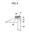
- Fig. 9 is a left side view of a first movable shade of the lamp unit of Fig. 7 ;
- Fig. 10 is a sectional view of a lamp unit according to a third exemplary embodiment pf the present invention.
- Fig. 11 is a partial perspective view of a shade unit of the lamp unit of Fig. 10 ;
- Fig. 12 is a left side view of a second movable shade of the shade unit shown in Fig. 11 ;
- Fig. 13A is a sectional view of the shade unit taken along a vertical plane S in Fig. 11 , illustrating a first movable shade in a closed position;
- Fig. 13B is another sectional view of the shade unit taken along the vertical plane S in Fig. 11 , illustrating the first movable shade in an open position.
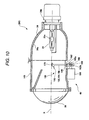
- Fig. 1 is a sectional view a vehicle headlamp 10 according to a first exemplary embodiment.
- the vehicle headlamp 10 has a lamp body 12, a transparent cover 14, and a lamp unit 20A.
- a left-hand side of Fig. 1 is the front side of the headlamp 10 and a right-hand side of Fig. 1 is the rear side of the headlamp 10.
- Fig. 1 is the sectional view of the vehicle headlamp 10 taken along a vertical plane which includes an optical axis X of the lamp unit 20A, and is viewed from the left of the headlamp 10.
- the lamp body 12 is formed in a box shape having an opening.
- the transparent cover 14 is made of a transparent resin or glass, and is formed in a saucer shape. An edge portion of the transparent cover 14 is fixed to an opening portion of the lamp body 12, whereby a lamp chamber is formed as a space surrounded by the lamp body 12 and the transparent cover 14.
- a holder 26 has a plurality of attaching portions 26a which project radially outward at a location in a vicinity of joining portions where the holder 26 is joined to a reflector 24.
- the lamp unit 20A is accommodated inside the lamp chamber. More specifically, the attaching portions 26a are attached to the lamp body 12 via a mounting mechanism 30 having bolts and nuts, whereby the lamp unit 20A is fixed in place inside the lamp chamber. An orientation of the optical axis X of the lamp unit 20A can be adjusted by adjusting positions where the nuts are fastened. That is, the mounting mechanism 30 functions as aiming device.
- the lamp unit 20A has a light source bulb 22, the holder 26, a projection lens 28 and an image forming section 40.
- the light source bulb 22 may be, for example, a discharge bulb such as a metal halide bulb which has a discharge light emitting portion thereinside as a light source 22a.
- the light source bulb 22 may be, for example, an incandescent lamp having a filament, e.g., a halogen lamp.
- the projection lens 28 is a planoconvex aspheric lens having a convex front surface and a flat rear surface.
- the projection lens 28 projects a light image, which is formed on a rear focal plane thereof, as an inverted image toward the front of the vehicle headlamp 10.
- the holder 26 is formed in a cylindrical shape which is opened on respective ends, and the projection lens 28 is attached to the front end of the holder 26.
- an image projected through the projection lens 28 will be explained as an image projected on an imaginary vertical screen which is disposed, for example, 25 meters ahead of the vehicle on which the headlamp 10 is mounted.
- an imaginary plane on which the image is projected is, of course, not limited to a vertical plane, and may be a horizontal plane which is assumed as including a road surface.
- the image forming section 40 includes the reflector 24 and a shade unit 50.
- the reflector 24 is formed in a cup shape, and an insertion hole 24b is formed in a bottom portion thereof.
- the light source bulb 22 is inserted into the insertion hole 24b and is fixed in place.
- An inner surface of the reflector 24 is mirror finished to form a reflecting surface 24a.
- a front end of the reflector 24 is joined to the rear end of the holder 26, whereby the reflector 24 and the holder 26 are fixed to each other such that the light source 22a is located on the optical axis X.
- the reflecting surface 24a of the reflector 24 reflects light from the light source 22a to form a light image on the rear focal plane of the projection lens 28.
- the shade unit 50 partially shields the light which is reflected by the reflector 24 toward the projection lens 28.
- the shade unit 50 has a first movable shade 52, a second movable shade 54, a third movable shade 56, solenoids 62, an auxiliary reflector 66, and a boundary shade 70.
- the solenoids 62 are fixed to one of the attaching portions 26a which is provided on a lower side of the holder 26. Each of the solenoids 62 has a plunger 64. The solenoids 62 are disposed such that the respective plungers 64 extend vertically upward from the corresponding solenoids 62.
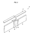
- Fig. 2 is a partial perspective view of the shade unit 50.
- the boundary shade 70 is formed in a shape of an elongated narrow plate, and there is a level difference on respective sides of an inclined portion which is provided substantially at a center of the boundary shade 70 in a longitudinal direction of the boundary shade 70. Respective ends of the boundary shade 70 are immovably fixed to the holder 26.
- the first movable shade 52, the second movable shade 54, and the third movable shade 56 are formed in rectangular shapes having different outlines.
- the auxiliary reflector 66 is fixed to a front surface of the first movable shade 52.
- the second movable shade 54 is disposed on the left of the first movable shade 52, and the third movable shade 56 is disposed on the right of the first movable shade 52.
- the second movable shade 54 has an overlap portion 54a which is recessed toward the rear.
- the overlap portion 54a is linearly formed, along a vertical direction, on a right end portion of the second movable shade 54.
- the second movable shade 54 is disposed such that a front surface of the overlap portion 54a abuts a rear surface of a left end portion of the first movable shade 52.
- the overlap portion 54a suppresses a leakage of light from a gap between the first movable shade 52 and the second movable shade 54.
- the third movable shade 56 has an overlap portion 56a which is recessed toward the rear.
- the overlap portion 56a is linearly formed, along the vertical direction, on a left end portion of the third movable shade 56.
- the third movable shade 56 is disposed such that a front surface of the overlap portion 56a abuts a rear surface of a right end portion of the first movable shade 52.
- the overlap portion 56a suppresses a leakage of light from a gap between the first movable shade 52 and the third movable shade 56.
- the overlap portions may alternatively be provided on the first movable shade 52.
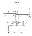
- Fig. 3 is a back view of the shade unit 50.
- the boundary shade 70 is disposed to extend in a horizontal direction.
- the boundary shade 70 has an upper surface (a boundary surface 70a) and a lower surface.
- the boundary surface 70a has a left portion, a right portion, and an inclined portion which is disposed between the left and right portions substantially at the center of the boundary surface 70a.
- the left portion horizontally extends from a left end of the boundary surface 70a to the inclined portion.
- the right portion horizontally extends, at a height lower than the left portion, from a right end of the boundary surface 70a to the inclined portion.
- the lower surface of the boundary shade 70 is stepped down from the rear to the front, and has a first lower surface 70c on the rear side and a second lower surface 70d on the front side.
- a thickness from the boundary surface 70a to the first lower surface 70c is uniform along the entire length of the boundary shade 70.
- a thickness from the boundary surface 70a to the second lower surface 70d is also uniform along the entire length of the boundary shade 70.
- each of the first lower surface 70c and the second lower surface 70d has a left portion, a right portion, and an inclined portion between the left and right portions.
- An upper end portion of the first movable shade 52 has an inclined portion which is formed to match the inclined portion of the first lower surface 70c of the boundary shade 70.
- the first movable shade 52, the second movable shade 54 and the third movable shade 56 are arranged side by side in a right-and-left direction such that upper end portions (distal end portions) thereof match the first lower surface 70c of the boundary shade 70 respectively.
- Each of the movable shades 52, 54, 56 is upwardly biased by a spring (not shown) toward the first lower surface 70c.
- Closing stoppers 72 are attached to the first lower surface 70c at locations corresponding to right upper ends and a left upper ends of the respective movable shades 52, 54, 56.
- Each of the movable shades 52, 54, 56 is biased upward to touch the respective closing stoppers 72, whereby an upward movement thereof is restricted.
- each of the movable shades 52, 54, 56 blocks a corresponding part of the light, which is reflected by the reflector 24, from entering the projection lens 28.
- the closing stoppers 72 may be made of a cushioning material in order to suppress noise from the movable shades 52, 54, 56.
- the boundary shade has a vertical overlap portion 70b between the first lower surface 70c and the second lower surface 70d.
- the overlap portion 70b is located in front of a gap between the first lower surface 70c and the respective movable shades 52, 54, 56, so that the boundary shade 70 and the movable shades 52, 54, 56 overlap each other in a direction along the optical axis X. Accordingly, when the movable shades 52, 54, 56 are in the closed positions, the overlap portion 70b suppresses a leakage of light toward the projection lens 28 from the gap between the upper ends (the distal ends) of the movable shades and the first lower surface 70c of the boundary shade 70.
- overlap portions may be provided on the respective movable shades 52, 54, 56 so as to suppress a leakage of light from the gap between the boundary shade 70 and the respective movable shades 52, 54, 56.
- the number of solenoids 62 is set to correspond to the number of movable shades.
- the number of solenoids 62 is set to three so as to correspond to the first movable shade 52, the second movable shade 54 and the third movable shade 56.
- a lower end portion of each of the movable shades 52, 54, 56 is coupled to an upper end portion of a plunger 64 of a respective one of the solenoids 62.
- the solenoid 62 When supplied with current (hereinafter, "when activated"), the solenoid 62 pulls down the plunger 64, so that the corresponding one of the movable shades 52, 54, 56 is moved downward together with the plunger 64.
- the solenoid 62 releases the plunger 64 from pulling downward, whereby the corresponding one of the movable shades 52, 54, 56 moves back to the closed position due to the biasing force of the spring.
- Fig. 4 is a back view of the shade unit 50 in which all the solenoids 62 are activated.
- the shade unit 50 has an opening stopper (not shown).
- Each of the movable shades 52, 54, 56 is restricted from continuing to move downward by hitting the opening stopper.
- each corresponding part of light, which is reflected by the reflector 24, is allowed to enter the projection lens 28.
- an "open position” for each of the movable shades 52, 54, 56, a position where the movable shade is in abutment with the opening stopper is referred to as an "open position."
- each of the movable shades 52, 54, 56 is movable between the closed position and the open position in the vertical direction, e.g., in a direction perpendicular to the optical axis X.
- the movable shades 52, 54, 56 may not necessarily be moved in the vertical direction, and may be moved in a direction having a certain angle with respect to the vertical direction. Further, the movable shades 52, 54, 56 may be moved in a direction which is not perpendicular to the optical axis X but intersecting the optical axis X.
- Fig. 5 is a diagram illustrating light distribution patterns formed by irradiating the imaginary vertical screen with light projected from the vehicle headlamp 10.
- the headlamp 10 is capable of producing a low beam light distribution pattern PL and a high beam light distribution pattern PH.
- the low beam light distribution pattern PL is for a left-hand traffic, and has a cutoff line along an upper edge thereof.
- the cutoff line includes a first cutoff line CL1, a second cutoff line CL2, and a third cutoff line CL3.
- the first cutoff line CL1 and the second cutoff line CL2 extend in a horizontal direction at different levels on respective sides of a line V-V which passes through a vanishing point H-V straight ahead of the vehicle on which the headlamp 10 is mounted.
- the first cutoff line CL1 extends in the horizontal direction in a region on the right of the line V-V and below the line H-H, and is used as a cutoff line for an oncoming lane.
- the third cutoff line CL3 extends obliquely upward to the left at an angle of about 15° from a left end of the first cutoff line CL1.
- the second cutoff line CL2 extends in the horizontal direction on the line H-H in a region on the left of the intersection point of the third cutoff line CL3 and the line H-H, and is used as a cutoff line for a lane in which the vehicle itself is traveling.
- An elbow point E is an intersection point of the first cutoff line CL1 and the line V-V, and is located in a position about 0.5° to 0.6° below the vanishing point H-V
- a hot zone HZ is a high luminous intensity zone, and is formed around the elbow point E, primarily on the left of the elbow point E.
- the high beam light distribution pattern PH is formed above the cutoff line of the low beam light distribution pattern PL in addition to the low beam light distribution pattern PL.
- the high beam light distribution pattern PH is divided into three sections, namely, a middle section PHM, a right section PHR and a left section PHL, by two vertical boundary lines on respective sides of the line V-V.
- the middle section PHM is formed when the first movable shade 52 is in the open position.
- the right area PHM is formed when the second movable shade 54 is in the open position.
- the left section PHL is formed when the third movable shade 56 is in the open position.
- the vehicle headlamp 10 produces the low beam light distribution pattern PL, and the cutoff line of the low beam light distribution pattern PL is formed by the boundary surface 70a of the boundary shade 70.
- the cutoff line may be formed by the upper ends of the movable shades 52, 54, 56 without providing the boundary shade 70.
- each of the movable shades 52, 54, 56 is moved in the vertical direction, there may be a misalignment of the upper ends when the movable shades 52, 54, 56 are in the closed positions.
- this misalignment may be a small misalignment in the shade unit 50, the misalignment is more recognizable on the imaginary vertical screen as an obvious misalignment of the cutoff line.
- the shade unit 50 of the exemplary embodiment includes the boundary shade 70, the cutoff line can accurately be formed regardless of the misalignment of the plurality of movable shades 52, 54, 56.
- the vehicle headlamp 10 When all of the movable shades 52, 54, 56 are in the open positions, the vehicle headlamp 10 produces the high beam light distribution pattern PH in addition to the low beam light distribution pattern PL.
- the vehicle on which the headlamp 10 is mounted may have a high beam switch (not shown), so that when the high beam switch is turned on by the driver, the solenoids 62 are activated to move all of the movable shades 52, 54, 56 to the open positions.
- the vehicle may also have an intermediate beam switch (not shown).
- an intermediate beam mode is initiated.
- the intermediate beam mode when there is a vehicle running ahead, such as an oncoming vehicle and/or a preceding vehicle, in a region corresponding to one or more of the right section PHR, the middle section PHM and the left section PHL, one or more of the movable shades 52, 54, 56 corresponding to the one or more of the right section PHR, the middle section PHM and the left section PHL is moved to or maintained in the closed position, and the other of the movable shades 52, 54, 56 is moved to or maintained in the open position. Accordingly, it is possible to improve forward visibility for the driver without giving a glare to the other driver of the vehicle running ahead.
- the vehicle on which the vehicle headlamp 10 is mounted may also have a camera (not shown) and a control unit (not shown).
- the control unit has, for example, a central processing unit (CPU) which executes various arithmetic operations, a read only memory (ROM) in which various control programs are stored, and a random access memory (RAM) which is used as a work area for storing data and executing programs, to control the vehicle headlamp 10.
- the camera has, for example, an imaging device such as a Charge Coupled Device (CCD) sensor or a Complementary Metal Oxide Semiconductor (CMOS) sensor, to capture images of a region ahead of the vehicle and to generate image data thereof.
- CCD Charge Coupled Device
- CMOS Complementary Metal Oxide Semiconductor
- the control unit When the intermediate beam switch is turned on by the driver, a signal is output to the control unit to initiate a light irradiation control of the headlamp 100.
- the control unit analyzes the image data from the camera, and determines whether there is a vehicle running ahead, e.g., an oncoming vehicle whose headlamps are turned on. When it is determined that there is a vehicle running ahead, the control unit then determines a position of the vehicle running ahead. A position of an oncoming vehicle may be determined, for example, from the positions of the headlamps in the analyzed image data.
- the control unit determines whether the vehicle running ahead is in a region corresponding to any of the middle section PHM, the right section PHR, and the left section PHL.
- the control unit deactivates, or maintain in a deactivated condition, one or more of the solenoids 62 coupled to the corresponding movable shades 52, 54, 56 so that the corresponding movable shades 52, 54, 56 are moved to or maintained in the closed positions, and activates or maintains in an activated condition the other of the solenoids 62 so that the other of the movable shades 52, 54, 56 are moved to or maintained in the open positions.
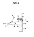
- Fig. 6 is a sectional view taken along the line VI-VI in Fig. 3 .
- the auxiliary reflector 66 is formed in a quadrangular prism shape, and is attached to the front surface of the first movable shade 52 at one end thereof.
- the auxiliary reflector 66 has an auxiliary reflecting surface 66a which is inclined downward toward the front.
- the auxiliary reflecting surface 66a may be formed by an aluminum deposition.
- Inside the lamp unit 20A there is an optical path Q of light which is reflected by an upper part of the reflecting surface 24a of the reflector 24 to pass above the boundary surface 70a.
- the auxiliary reflecting surface 66a reflects the light, which is incident thereon along the optical path Q, toward the projection lens 28. According to this configuration, the light enters the projection lens 28 as if it is incident on the projection lens 28 along an imaginary optical path R which passes a focal plane F of the projection lens 28 at a position below the boundary surface 70a.
- the auxiliary reflecting surface 66a makes it possible to irradiate, when the first movable shade 52 is in the closed position so that the middle section PHM of the high beam light distribution pattern PH is not formed, an overhead sign region, which is above the cutoff line CL and around the line V-V, with the light reflected by the auxiliary reflecting surface 66a.
- the second lower surface 70d of the boundary shade 70 is mirror finished by, for example, an aluminum deposition to function as a reflecting face.
- the corresponding part of the light is blocked from entering the projection lens 28 and the leakage of light from a gap between the one of the movable shade 52, 54, 56 and the boundary shade 70 is suppressed by the overlap portion 70b.
- the one of the movable shades 52, 54, 56 is in the open position, the corresponding part of light is partially reflected by the second lower surface 70d so as to be incident on the projection lens 28, thereby suppressing a part of a projected image that corresponds to the boundary shade 70 from being dark.
- Fig. 7 is a sectional view of a lamp unit 20B according to a second exemplary embodiment of the present invention.
- the sectional view is taken along a vertical plane including an optical axis X, and is viewed from the left of the lamp unit 20B.
- portions of the lamp unit 20B that are similar to those of the lamp unit 20A will be designated by the same reference numerals, and detailed explanation thereof will be omitted.
- the lamp unit 20B has a similar configuration to that of the lamp unit 20A, except that a shade unit 100 is provided instead of the shade unit 50 and that a holder 98 is provided instead of the holder 26.
- the shade unit 100 includes a boundary shade 70, a first movable shade 102, a second movable shade 104, a third movable shade 106 and solenoids 114.
- Fig. 8 is a partial perspective view of the shade unit 100.
- the first movable shade 102, the second movable shade 104 and the third movable shade 106 are formed in rectangular shapes having different outlines. A lower part of each of the movable shades 102, 104, 106 is bent toward the front.
- An auxiliary reflector 66 is fixed to a front surface of the first movable shade 102.
- the second movable shade 104 is disposed on the left of the first movable shade 102, and the third movable shade 106 is disposed on the right of the first movable shade 102.
- An upper end of the first movable shade 102 has an inclined portion which matches an inclined portion of a first lower surface 70c of the boundary shade 70.
- the first movable shade 102, the second movable shade 104 and the third movable shade 106 are arranged side by side in a right-and-left direction such that upper ends (distal ends) thereof match the first lower surface 70c.
- each of the movable shades 102, 104, 106 has support portions 110 on right and left sides.
- Each of the support portions is formed with a shaft hole 110a penetrating through the support portion 110 in the right-and-left direction.
- an opening is formed in a lower part of the holder 98, where a rotational shaft 99 is attached to the holder 98 to horizontally extend in a direction perpendicular to the optical axis X.
- the rotational shaft 99 is inserted through the shaft holes 110a of the support portions 110 of each of the movable shades 102, 104, 106. Accordingly, the movable shades 102, 104, 106 are individually rotatable about the rotational shaft 99.
- Fig. 9 is a left side view of the first movable shade 102.
- closing stoppers 72 are not provided on the first lower surface 70c of the boundary shade 70. Instead, a plurality of closing stoppers 108 are provided on a overlap portion 70b of the boundary shade 70.
- the positions of the closing stoppers 108 in the right-and-left direction are similar to those of the closing stoppers 72 in the first exemplary embodiment.
- Each of the movable shades 102, 104, 106 is biased to rotate toward the front by a coil spring (not shown), and when the movable shade hits the closing stoppers 108, the forward rotation thereof is restricted.
- a position where the movable shade is in abutment with the closing stoppers 108 is referred to as a "closed position."
- a coupling member 112 is provided on a lower surface of each of the movable shades 102, 104, 106.
- Each of the coupling members 112 is formed with a slot 112a penetrating through the connecting portion 112 in the right-and-left direction.
- the slot 112a is provided to extend in the vertical direction when the corresponding one of the movable shades 102, 104, 106 is in the closed position.
- Each of the solenoids 114 is associated with a corresponding one of the movable shades 102, 104, 106.
- the solenoids 114 are fixed to a lower surface 24c of a reflector 24 such that respective plungers 116 extend to the front.
- a pin 118 is fixed to a distal end portion of the plunger 116 to extend in the right-and-left direction.
- the pin 118 is inserted into the slot 112a of the corresponding coupling member 112.
- the solenoid 114 pushes out the corresponding plunger 116 to the front, whereby the coupling member 112 is pushed to the front and the corresponding one of the movable shades 102, 104, 106 rotates about the rotational shaft 99 such that the upper end thereof downwardly moves to the rear.
- the shade unit 100 has an opening stopper (not shown).
- Each of the movable shades 102, 104, 106 is restricted from continuing to rotate downwards by hitting the opening stopper.
- the movable shades 102, 104, 106 are moved downward, the corresponding part of the light, which is reflected by the reflector 24, is allowed to enter the projection lens 28.
- an "open position” a position where the movable shade is rotated downward to be in abutment with the opening stopper.
- the low beam light distribution pattern PL is formed, and the cutoff line thereof is formed by the boundary shade 70. The region above the cutoff line is not irradiated.
- the first movable shade 102 is moved to the open position, the corresponding part of the light, which is reflected by the reflector 24, is allowed to enter the projection lens 28 to irradiate the middle section PHM on an imaginary vertical screen.
- the second movable shade 104 is moved to the open position, the corresponding part of the light, which is reflected by the reflector 24, is allowed to enter the projection lens 28 to irradiate the right section PHR on the imaginary vertical screen.
- the third movable shade 106 is moved to the open position, the corresponding part of the light, which is reflected by the reflector 24, is allowed to enter the projection lens 28 to irradiate the left section PHL on the imaginary vertical screen.
- each of the movable shades 102, 104, 106 is rotatable about the horizontal shaft 99 which is perpendicular to the optical axis X so as to move between the closed position and the open position.
- Each of the movable shades 102, 104, 106 is rotatable such that the upper end thereof downwardly moves to the rear. According to the rotating movement of the movable shades 102, 104, 106, it is also possible to block the light from entering the projections lens 28 and to allow the light to enter the projection lens 28.
- a vehicle on which the lamp unit 20B is mounted may also have an intermediate beam mode.
- Fig. 10 is a sectional view of a lamp unit 20C according to a third exemplary embodiment of the present invention.
- the sectional view is taken along a vertical plane including an optical axis X, and is viewed from the left of the lamp unit 20C.
- portions of the lamp unit 20C that are similar to those of the lamp units 20A, 20B described above will be designated by the same reference numerals, and detailed explanation thereof will be omitted.
- the lamp unit 20C has a similar configuration to that of the lamp unit 20A, except that a shade unit 150 is provided instead of the shade unit 50 and that a holder 148 is provided instead of the holder 26.
- the shade unit 150 includes a first movable shade 152, a second movable shade 154, a third movable shade 156, an auxiliary reflector 158, solenoids 164, and a boundary shade 170.
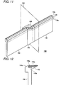
- Fig. 11 is a partial perspective view of the shade unit 150.
- the boundary shade 170 is formed in a shape of an elongated narrow plate, and there is a level difference on respective sides of an inclined portion which is provided substantially at a center of the boundary shade 170 in a longitudinal direction of the boundary shade 170.
- the movable shades 152, 154, 156 are formed in rectangular shapes having different outlines.
- the auxiliary reflector 158 is fixed to a front surface of the first movable shade 152.
- the second movable shade 154 is disposed on the left of the first movable shade 152, and the third movable shade 156 is disposed on the right of the first movable shade 152.
- the boundary shade 170 is disposed to extend in a horizontal direction.
- the boundary shade 170 has an upper surface (a boundary surface 170a) and a lower surface 170b.
- the boundary surface 170a has an inclined portion in the middle, a left portion which horizontally extends from a left end of the inclined portion, and a right portion which horizontally extends from a right end of the inclined portion at a height which is lower than the left portion.
- a thickness from the boundary surface 170a to the lower surface 170b is uniform along the entire length of the boundary shade 170.
- the lower surface 170b also has a left portion and a right portion which horizontally extend at different levels on respective sides of an inclined portion.
- An upper end of the first movable shade 152 has an inclined portion which matches the inclined portion of the lower surface 170b of the boundary shade 70.
- the first movable shade 152, the second movable shade 154 and the third movable shade 156 are provided side by side in a right-and-left direction such that upper ends (distal ends) thereof match the lower surface 170b.
- a coupling member 162 is fixed to a lower end of each of the movable shades 152, 154, 156.
- Each of the coupling members 162 is an elongated narrow plate member, and is formed with a shaft hole 162a penetrating the coupling member 162 in the right-and-left direction.
- a lower part of the holder 148 is formed with an opening where a rotational shaft 149 is attached to the holder 148 to horizontally extend in a direction perpendicular to the optical axis X.
- the rotational shaft 149 is inserted into the shaft holes 162a of the coupling members 162 which are attached to the respective movable shades 152, 154, 156. Accordingly, each of the movable shades 152, 154, 156 is individually rotatable about the rotational shaft 149.
- the solenoids 164 are associated with corresponding ones of the movable shades 152, 154, 156.
- the solenoids 164 are fixed to a lower surface of the holder 148 such that plungers 166 thereof extend to the rear.
- a pin 168 is fixed to a distal end portion of the plunger 166 to extend in the right-and-left direction. The pin 168 is inserted into a slot 162b of the corresponding coupling member 162.
- the solenoid 164 When the solenoid 164 is activated, the solenoid 164 pushes out the corresponding plunger 166 to the rear, so that the coupling member 162 is also pushed out to the rear and the corresponding one of the movable shades 152, 154, 156 is rotated about the rotational shaft 149 such that the upper end thereof downwardly moves to the front.
- Fig. 12 is a left side view of the second movable shade 154.
- the second movable shade 154 has an overlap portion 154a on the upper end thereof.
- the overlap portion 154a is disposed so as to cover a gap between the lower surface 170a of the boundary shade 170 and the upper end of the second movable shade 154 from the front.
- Overlap portions which are similar to this overlap portion 154a, are also provided on the first movable shade 152 and the third movable shade 156 respectively. According to this configuration, the leakage of light from the gap between the lower surface 170b of the boundary shade 170 and the upper ends of the respective movable shades 152, 154, 156 toward the projection lens 28 can be suppressed.
- the overlap portions may be provided on the boundary shade 170 instead of the movable shades 152, 154, 156 to similarly suppress the leakage of light from the gap between the lower surface 170b of the boundary shade 170 and the respective movable shades 152, 154, 156.
- an inclined portion 154b is formed on the upper end of the second movable shade 154 so as to downwardly extend toward the front. Similar inclined portions are also provided on the first movable shade 152 and the third movable shade 156 respectively. By providing these inclined portions, the light reflected by the reflector 24 is prevented from being blocked by the upper ends of the respective movable shades 152, 154, 156.
- a plurality of closing stoppers 172 are provided on the lower surface 170b. Positions of the closing stoppers 172 in the right-and-left direction are similar to those of the closing stoppers 72 in the first exemplary embodiment.
- the closing stoppers 172 are brought into abutment with rear surfaces of upper end portions of the respective movable shades 152, 154, 156, so as to restrict the movable shades 152, 154, 156 from continuing to rotate to the rear.
- a position where the movable shade is in abutment with the corresponding stoppers 172 will be referred to as a "closed position."
- the shade unit 150 has an opening stopper (not shown), and each of the movable shades 152, 154, 156 is restricted from continuing to rotate downwards by hitting the opening stopper.
- the movable shades 152, 154, 156 is moved downward, the corresponding part of the light, which is reflected by the reflector 24, is allowed to enter the projection lens 28.
- an "open position” for each of the movable shades 152, 154, 156, a position where the movable shade is rotated downward to be in abutment with the opening stopper.
- the low beam light distribution pattern PL is formed, and the cutoff line of the low beam light distribution pattern PL is formed by the boundary shade 170. A region above the cutoff line is not irradiated.
- the first movable shade 152 is moved to the open position, the corresponding part of the light, which is reflected by the reflector 24, is allowed to enter the projection lens 28 to irradiate the middle section PHM on an imaginary vertical screen.
- the second movable shade 154 is moved to the open position, the corresponding part of the light, which is reflected by the reflector 24, is allowed to enter the projection lens 28 to irradiate the right section PHR on the imaginary vertical screen.
- the third movable shade 156 is moved to the open position, the corresponding part of the light, which is reflected by the reflector 24, is allowed to enter the projection lens 28 to irradiate the left section PHL on the imaginary vertical screen.
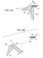
- Fig. 13A is a sectional view of the first movable shade 152 in the closed position, taken along a vertical plane S in Fig. 11 and viewed from the left.
- the vertical plane S is parallel to the optical axis X
- the auxiliary reflector 158 is rectangular when viewed from above.
- the auxiliary reflector 158 has an auxiliary reflecting surface 158a which is inclined downwards toward the front.
- the auxiliary reflecting surface 158a is formed by, for example, an aluminum deposition.
- an overhead sign region can be irradiated with the light reflected by the auxiliary reflecting surface 158a, like the auxiliary reflecting surface 66a of the first exemplary embodiment.
- the lower surface 170b of the boundary shade 170 is mirror finished by, for example, an aluminum deposition to functions as a reflecting face.
- an aluminum deposition to functions as a reflecting face.
- the corresponding part of the light is blocked from entering the projection lens 28.
- the corresponding part of the light is partially reflected by the lower surface 170b to enter the projection lens 28.
- Fig. 13B is a sectional view of the first movable shade 152 in the open position, taken along the vertical plane S shown in Fig. 11 and viewed from the left.
- a rear surface 152a of the first movable shade 152 is also mirror finished by, for example, an aluminum deposition to function as a reflecting face.
- the rear surface 152a reflects the light from the reflector 24 toward the projection lens 28 to irradiate the overhead sign region.
- the auxiliary reflecting surface 158a of the auxiliary reflector 158 reflects the light from the reflector 24 to irradiate the overhead sign region.
- the rear surface 152a of the first movable shade 152 reflects the light from the reflector 24 to irradiate the overhead sign region. Accordingly, it is possible to irradiate the overhead sign region, irrespective of whether the first movable shade 152 is in the closed position or in the open position.
- each of the movable shades 152, 154, 156 is rotatable about the horizontal shaft 149 which perpendicular to the optical axis X to move between the closed position and the open position.
- the movable shades 152, 154, 156 are rotatable such that the upper ends thereof downwardly move to the front. According to this rotating movement of the movable shades 152, 154, 156, it is also possible to block the light from entering the projections lens 28 and to allow the light to enter the projection lens 28.
- a vehicle on which the lamp unit 20C is mounted may also have an intermediate beam mode.
Abstract
Description
- Apparatuses consistent with the present invention relate to a vehicle headlamp and, more particularly, to a projector-type vehicle headlamp having a movable shade.
- A related art projector-type vehicle headlamp has a movable shade (see, e.g.,
JP 2006-040785 A - For the driver of the vehicle, forward visibility is improved when the region above the cutoff line is irradiated in addition to the low beam light distribution pattern. However, if the vehicle is driven with the irradiation to the region above the cutoff line being maintained, a glare may be given to other drivers of vehicles running ahead such as oncoming vehicles and preceding vehicles.
- In view of the foregoing, illustrative aspects of the present invention provide a vehicle headlamp which can suitably improve forward visibility for a driver without giving a glare to other drivers of vehicles running ahead.
- According to an illustrative aspect of the present invention, a vehicle headlamp is provided. The vehicle headlamp includes a light source, an image forming section which forms a light image using light from the light source, and a projection lens which projects the light image. An optical axis extends from the light source and passes through the projection lens. The image forming section includes a plurality of movable shades and a boundary shade. The movable shades are arranged side by side, and each of the movable shades is individually movable between a closed position at which the movable shade blocks a corresponding part of the light from entering the projection lens and an open position at which the movable shade allows the corresponding part of the light to enter the projection lens. Each of the movable shades has a distal end. The boundary shade is disposed to extend along the distal ends that are arranged side by side when the plurality of movable shades are in the closed positions. When the plurality of movable shades are in the closed positions, the boundary shade forms a boundary line of the light image.
- Other aspects and advantages of the invention will be apparent from the following description, the drawings and the claims.
-
Fig. 1 is a sectional view a vehicle headlamp according to a first exemplary embodiment of the present invention; -
Fig. 2 is a partial perspective view of a shade unit of the vehicle headlamp ofFig. 1 ; -
Fig. 3 is a back view of the shade unit ofFig. 2 ; -
Fig. 4 is another back view of the shade unit ofFig. 2 in which solenoids are activated; -
Fig. 5 is a diagram illustrating light distribution patterns to be formed by irradiating an imaginary vertical screen with light projected from the vehicle headlamp ofFig. 1 ; -
Fig. 6 is a sectional view taken along a line VI-VI inFig. 3 ; -
Fig. 7 is a sectional view of a lamp unit according to a second exemplary embodiment of the present invention; -
Fig. 8 is a partial perspective view of a shade unit of the lamp unit ofFig. 7 ; -
Fig. 9 is a left side view of a first movable shade of the lamp unit ofFig. 7 ; -
Fig. 10 is a sectional view of a lamp unit according to a third exemplary embodiment pf the present invention; -
Fig. 11 is a partial perspective view of a shade unit of the lamp unit ofFig. 10 ; -
Fig. 12 is a left side view of a second movable shade of the shade unit shown inFig. 11 ; -
Fig. 13A is a sectional view of the shade unit taken along a vertical plane S inFig. 11 , illustrating a first movable shade in a closed position; and -
Fig. 13B is another sectional view of the shade unit taken along the vertical plane S inFig. 11 , illustrating the first movable shade in an open position. - Hereinafter, exemplary embodiments of the present invention will be explained in detail with reference to the drawings. The following exemplary embodiments are examples only and do not limit the scope of the present invention as defined by the claims.
- First Exemplary Embodiment
-
Fig. 1 is a sectional view avehicle headlamp 10 according to a first exemplary embodiment. Thevehicle headlamp 10 has alamp body 12, atransparent cover 14, and alamp unit 20A. A left-hand side ofFig. 1 is the front side of theheadlamp 10 and a right-hand side ofFig. 1 is the rear side of theheadlamp 10.Fig. 1 is the sectional view of thevehicle headlamp 10 taken along a vertical plane which includes an optical axis X of thelamp unit 20A, and is viewed from the left of theheadlamp 10. - The
lamp body 12 is formed in a box shape having an opening. Thetransparent cover 14 is made of a transparent resin or glass, and is formed in a saucer shape. An edge portion of thetransparent cover 14 is fixed to an opening portion of thelamp body 12, whereby a lamp chamber is formed as a space surrounded by thelamp body 12 and thetransparent cover 14. - A
holder 26 has a plurality of attachingportions 26a which project radially outward at a location in a vicinity of joining portions where theholder 26 is joined to areflector 24. Thelamp unit 20A is accommodated inside the lamp chamber. More specifically, the attachingportions 26a are attached to thelamp body 12 via amounting mechanism 30 having bolts and nuts, whereby thelamp unit 20A is fixed in place inside the lamp chamber. An orientation of the optical axis X of thelamp unit 20A can be adjusted by adjusting positions where the nuts are fastened. That is, themounting mechanism 30 functions as aiming device. - The
lamp unit 20A has alight source bulb 22, theholder 26, aprojection lens 28 and animage forming section 40. Thelight source bulb 22 may be, for example, a discharge bulb such as a metal halide bulb which has a discharge light emitting portion thereinside as alight source 22a. Alternatively, thelight source bulb 22 may be, for example, an incandescent lamp having a filament, e.g., a halogen lamp. Theprojection lens 28 is a planoconvex aspheric lens having a convex front surface and a flat rear surface. Theprojection lens 28 projects a light image, which is formed on a rear focal plane thereof, as an inverted image toward the front of thevehicle headlamp 10. Theholder 26 is formed in a cylindrical shape which is opened on respective ends, and theprojection lens 28 is attached to the front end of theholder 26. - In this description, an image projected through the
projection lens 28 will be explained as an image projected on an imaginary vertical screen which is disposed, for example, 25 meters ahead of the vehicle on which theheadlamp 10 is mounted. However, an imaginary plane on which the image is projected is, of course, not limited to a vertical plane, and may be a horizontal plane which is assumed as including a road surface. - The
image forming section 40 includes thereflector 24 and ashade unit 50. Thereflector 24 is formed in a cup shape, and aninsertion hole 24b is formed in a bottom portion thereof. Thelight source bulb 22 is inserted into theinsertion hole 24b and is fixed in place. An inner surface of thereflector 24 is mirror finished to form a reflectingsurface 24a. A front end of thereflector 24 is joined to the rear end of theholder 26, whereby thereflector 24 and theholder 26 are fixed to each other such that thelight source 22a is located on the optical axis X. The reflectingsurface 24a of thereflector 24 reflects light from thelight source 22a to form a light image on the rear focal plane of theprojection lens 28. - The
shade unit 50 partially shields the light which is reflected by thereflector 24 toward theprojection lens 28. Theshade unit 50 has a firstmovable shade 52, a secondmovable shade 54, a thirdmovable shade 56,solenoids 62, anauxiliary reflector 66, and aboundary shade 70. - The
solenoids 62 are fixed to one of the attachingportions 26a which is provided on a lower side of theholder 26. Each of thesolenoids 62 has aplunger 64. Thesolenoids 62 are disposed such that therespective plungers 64 extend vertically upward from the correspondingsolenoids 62. -
Fig. 2 is a partial perspective view of theshade unit 50. Theboundary shade 70 is formed in a shape of an elongated narrow plate, and there is a level difference on respective sides of an inclined portion which is provided substantially at a center of theboundary shade 70 in a longitudinal direction of theboundary shade 70. Respective ends of theboundary shade 70 are immovably fixed to theholder 26. - The first
movable shade 52, the secondmovable shade 54, and the thirdmovable shade 56 are formed in rectangular shapes having different outlines. Theauxiliary reflector 66 is fixed to a front surface of the firstmovable shade 52. The secondmovable shade 54 is disposed on the left of the firstmovable shade 52, and the thirdmovable shade 56 is disposed on the right of the firstmovable shade 52. - The second
movable shade 54 has anoverlap portion 54a which is recessed toward the rear. Theoverlap portion 54a is linearly formed, along a vertical direction, on a right end portion of the secondmovable shade 54. The secondmovable shade 54 is disposed such that a front surface of theoverlap portion 54a abuts a rear surface of a left end portion of the firstmovable shade 52. Theoverlap portion 54a suppresses a leakage of light from a gap between the firstmovable shade 52 and the secondmovable shade 54. - Likewise, the third
movable shade 56 has anoverlap portion 56a which is recessed toward the rear. Theoverlap portion 56a is linearly formed, along the vertical direction, on a left end portion of the thirdmovable shade 56. The thirdmovable shade 56 is disposed such that a front surface of theoverlap portion 56a abuts a rear surface of a right end portion of the firstmovable shade 52. Theoverlap portion 56a suppresses a leakage of light from a gap between the firstmovable shade 52 and the thirdmovable shade 56. Instead of providing the overlap portions on the secondmovable shade 54 and the thirdmovable shade 56, the overlap portions may alternatively be provided on the firstmovable shade 52. -
Fig. 3 is a back view of theshade unit 50. Theboundary shade 70 is disposed to extend in a horizontal direction. Theboundary shade 70 has an upper surface (aboundary surface 70a) and a lower surface. Theboundary surface 70a has a left portion, a right portion, and an inclined portion which is disposed between the left and right portions substantially at the center of theboundary surface 70a. The left portion horizontally extends from a left end of theboundary surface 70a to the inclined portion. The right portion horizontally extends, at a height lower than the left portion, from a right end of theboundary surface 70a to the inclined portion. - The lower surface of the
boundary shade 70 is stepped down from the rear to the front, and has a firstlower surface 70c on the rear side and a secondlower surface 70d on the front side. A thickness from theboundary surface 70a to the firstlower surface 70c is uniform along the entire length of theboundary shade 70. A thickness from theboundary surface 70a to the secondlower surface 70d is also uniform along the entire length of theboundary shade 70. Like theboundary surface 70a, each of the firstlower surface 70c and the secondlower surface 70d has a left portion, a right portion, and an inclined portion between the left and right portions. - An upper end portion of the first
movable shade 52 has an inclined portion which is formed to match the inclined portion of the firstlower surface 70c of theboundary shade 70. The firstmovable shade 52, the secondmovable shade 54 and the thirdmovable shade 56 are arranged side by side in a right-and-left direction such that upper end portions (distal end portions) thereof match the firstlower surface 70c of theboundary shade 70 respectively. - Each of the
movable shades lower surface 70c. Closingstoppers 72 are attached to the firstlower surface 70c at locations corresponding to right upper ends and a left upper ends of the respectivemovable shades movable shades respective closing stoppers 72, whereby an upward movement thereof is restricted. When in abutment with theclosing stoppers 72, each of themovable shades reflector 24, from entering theprojection lens 28. Hereinafter, for each of themovable shades closing stoppers 72 on the firstlower surface 70c of theboundary shade 70 is referred to as a "closed position." Theclosing stoppers 72 may be made of a cushioning material in order to suppress noise from themovable shades - The boundary shade has a
vertical overlap portion 70b between the firstlower surface 70c and the secondlower surface 70d. When themovable shades overlap portion 70b is located in front of a gap between the firstlower surface 70c and the respectivemovable shades boundary shade 70 and themovable shades movable shades overlap portion 70b suppresses a leakage of light toward theprojection lens 28 from the gap between the upper ends (the distal ends) of the movable shades and the firstlower surface 70c of theboundary shade 70. Instead of providing the overlap portion on theboundary shade 70, overlap portions may be provided on the respectivemovable shades boundary shade 70 and the respectivemovable shades - The number of
solenoids 62 is set to correspond to the number of movable shades. Thus, in this exemplary embodiment, the number ofsolenoids 62 is set to three so as to correspond to the firstmovable shade 52, the secondmovable shade 54 and the thirdmovable shade 56. A lower end portion of each of themovable shades plunger 64 of a respective one of thesolenoids 62. - When supplied with current (hereinafter, "when activated"), the
solenoid 62 pulls down theplunger 64, so that the corresponding one of themovable shades plunger 64. When the supply of current is stopped (hereinafter, referred to as "deactivated"), thesolenoid 62 releases theplunger 64 from pulling downward, whereby the corresponding one of themovable shades -
Fig. 4 is a back view of theshade unit 50 in which all thesolenoids 62 are activated. Theshade unit 50 has an opening stopper (not shown). Each of themovable shades movable shades reflector 24, is allowed to enter theprojection lens 28. Hereinafter, for each of themovable shades - As described above, each of the
movable shades movable shades movable shades -
Fig. 5 is a diagram illustrating light distribution patterns formed by irradiating the imaginary vertical screen with light projected from thevehicle headlamp 10. - The
headlamp 10 is capable of producing a low beam light distribution pattern PL and a high beam light distribution pattern PH. The low beam light distribution pattern PL is for a left-hand traffic, and has a cutoff line along an upper edge thereof. The cutoff line includes a first cutoff line CL1, a second cutoff line CL2, and a third cutoff line CL3. The first cutoff line CL1 and the second cutoff line CL2 extend in a horizontal direction at different levels on respective sides of a line V-V which passes through a vanishing point H-V straight ahead of the vehicle on which theheadlamp 10 is mounted. The first cutoff line CL1 extends in the horizontal direction in a region on the right of the line V-V and below the line H-H, and is used as a cutoff line for an oncoming lane. The third cutoff line CL3 extends obliquely upward to the left at an angle of about 15° from a left end of the first cutoff line CL1. The second cutoff line CL2 extends in the horizontal direction on the line H-H in a region on the left of the intersection point of the third cutoff line CL3 and the line H-H, and is used as a cutoff line for a lane in which the vehicle itself is traveling. - An elbow point E is an intersection point of the first cutoff line CL1 and the line V-V, and is located in a position about 0.5° to 0.6° below the vanishing point H-V A hot zone HZ is a high luminous intensity zone, and is formed around the elbow point E, primarily on the left of the elbow point E.
- The high beam light distribution pattern PH is formed above the cutoff line of the low beam light distribution pattern PL in addition to the low beam light distribution pattern PL. The high beam light distribution pattern PH is divided into three sections, namely, a middle section PHM, a right section PHR and a left section PHL, by two vertical boundary lines on respective sides of the line V-V. The middle section PHM is formed when the first
movable shade 52 is in the open position. The right area PHM is formed when the secondmovable shade 54 is in the open position. The left section PHL is formed when the thirdmovable shade 56 is in the open position. - When all of the
movable shades vehicle headlamp 10 produces the low beam light distribution pattern PL, and the cutoff line of the low beam light distribution pattern PL is formed by theboundary surface 70a of theboundary shade 70. - Here, it may be possible to form the cutoff line by the upper ends of the
movable shades boundary shade 70. However, because each of themovable shades movable shades shade unit 50, the misalignment is more recognizable on the imaginary vertical screen as an obvious misalignment of the cutoff line. To the contrary, because theshade unit 50 of the exemplary embodiment includes theboundary shade 70, the cutoff line can accurately be formed regardless of the misalignment of the plurality ofmovable shades - When all of the
movable shades vehicle headlamp 10 produces the high beam light distribution pattern PH in addition to the low beam light distribution pattern PL. The vehicle on which theheadlamp 10 is mounted may have a high beam switch (not shown), so that when the high beam switch is turned on by the driver, thesolenoids 62 are activated to move all of themovable shades - The vehicle may also have an intermediate beam switch (not shown). When the intermediate beam switch is turned on by the driver, an intermediate beam mode is initiated. In the intermediate beam mode, when there is a vehicle running ahead, such as an oncoming vehicle and/or a preceding vehicle, in a region corresponding to one or more of the right section PHR, the middle section PHM and the left section PHL, one or more of the
movable shades movable shades - More specifically, the vehicle on which the
vehicle headlamp 10 is mounted may also have a camera (not shown) and a control unit (not shown). The control unit has, for example, a central processing unit (CPU) which executes various arithmetic operations, a read only memory (ROM) in which various control programs are stored, and a random access memory (RAM) which is used as a work area for storing data and executing programs, to control thevehicle headlamp 10. The camera has, for example, an imaging device such as a Charge Coupled Device (CCD) sensor or a Complementary Metal Oxide Semiconductor (CMOS) sensor, to capture images of a region ahead of the vehicle and to generate image data thereof. The camera is coupled to the control unit, and the image data is output to the control unit. - When the intermediate beam switch is turned on by the driver, a signal is output to the control unit to initiate a light irradiation control of the
headlamp 100. During the intermediate beam mode, the control unit analyzes the image data from the camera, and determines whether there is a vehicle running ahead, e.g., an oncoming vehicle whose headlamps are turned on. When it is determined that there is a vehicle running ahead, the control unit then determines a position of the vehicle running ahead. A position of an oncoming vehicle may be determined, for example, from the positions of the headlamps in the analyzed image data. When the position of the vehicle running ahead is determined, the control unit then determines whether the vehicle running ahead is in a region corresponding to any of the middle section PHM, the right section PHR, and the left section PHL. When it is determined that the vehicle running ahead is in a region corresponding to one or more of the sections PHM, PHR, PHL, the control unit deactivates, or maintain in a deactivated condition, one or more of thesolenoids 62 coupled to the correspondingmovable shades movable shades solenoids 62 so that the other of themovable shades -
Fig. 6 is a sectional view taken along the line VI-VI inFig. 3 . Theauxiliary reflector 66 is formed in a quadrangular prism shape, and is attached to the front surface of the firstmovable shade 52 at one end thereof. Theauxiliary reflector 66 has anauxiliary reflecting surface 66a which is inclined downward toward the front. Theauxiliary reflecting surface 66a may be formed by an aluminum deposition. Inside thelamp unit 20A, there is an optical path Q of light which is reflected by an upper part of the reflectingsurface 24a of thereflector 24 to pass above theboundary surface 70a. Theauxiliary reflecting surface 66a reflects the light, which is incident thereon along the optical path Q, toward theprojection lens 28. According to this configuration, the light enters theprojection lens 28 as if it is incident on theprojection lens 28 along an imaginary optical path R which passes a focal plane F of theprojection lens 28 at a position below theboundary surface 70a. - When the first
movable shade 52 is in the closed position, light incident on the focal plane F of theprojection lens 28 below theboundary surface 70a is blocked. However, because theauxiliary reflecting surface 66a is provided, a light image can be formed below theboundary surface 70a even when the firstmovable shade 52 is in the closed position. Theauxiliary reflecting surface 66a thus makes it possible to irradiate, when the firstmovable shade 52 is in the closed position so that the middle section PHM of the high beam light distribution pattern PH is not formed, an overhead sign region, which is above the cutoff line CL and around the line V-V, with the light reflected by theauxiliary reflecting surface 66a. - The second
lower surface 70d of theboundary shade 70 is mirror finished by, for example, an aluminum deposition to function as a reflecting face. When one of themovable shades projection lens 28 and the leakage of light from a gap between the one of themovable shade boundary shade 70 is suppressed by theoverlap portion 70b. On the other hand, when the one of themovable shades lower surface 70d so as to be incident on theprojection lens 28, thereby suppressing a part of a projected image that corresponds to theboundary shade 70 from being dark. - Second Exemplary Embodiment
-
Fig. 7 is a sectional view of alamp unit 20B according to a second exemplary embodiment of the present invention. The sectional view is taken along a vertical plane including an optical axis X, and is viewed from the left of thelamp unit 20B. Hereinafter, portions of thelamp unit 20B that are similar to those of thelamp unit 20A will be designated by the same reference numerals, and detailed explanation thereof will be omitted. - The
lamp unit 20B has a similar configuration to that of thelamp unit 20A, except that ashade unit 100 is provided instead of theshade unit 50 and that aholder 98 is provided instead of theholder 26. Theshade unit 100 includes aboundary shade 70, a firstmovable shade 102, a secondmovable shade 104, a thirdmovable shade 106 andsolenoids 114. -
Fig. 8 is a partial perspective view of theshade unit 100. The firstmovable shade 102, the secondmovable shade 104 and the thirdmovable shade 106 are formed in rectangular shapes having different outlines. A lower part of each of themovable shades auxiliary reflector 66 is fixed to a front surface of the firstmovable shade 102. The secondmovable shade 104 is disposed on the left of the firstmovable shade 102, and the thirdmovable shade 106 is disposed on the right of the firstmovable shade 102. - An upper end of the first
movable shade 102 has an inclined portion which matches an inclined portion of a firstlower surface 70c of theboundary shade 70. The firstmovable shade 102, the secondmovable shade 104 and the thirdmovable shade 106 are arranged side by side in a right-and-left direction such that upper ends (distal ends) thereof match the firstlower surface 70c. - The lower part of each of the
movable shades support portions 110 on right and left sides. Each of the support portions is formed with ashaft hole 110a penetrating through thesupport portion 110 in the right-and-left direction. - As shown in
Fig. 7 , an opening is formed in a lower part of theholder 98, where arotational shaft 99 is attached to theholder 98 to horizontally extend in a direction perpendicular to the optical axis X. Therotational shaft 99 is inserted through the shaft holes 110a of thesupport portions 110 of each of themovable shades movable shades rotational shaft 99. -
Fig. 9 is a left side view of the firstmovable shade 102. In the second exemplary embodiment, closingstoppers 72 are not provided on the firstlower surface 70c of theboundary shade 70. Instead, a plurality of closingstoppers 108 are provided on aoverlap portion 70b of theboundary shade 70. The positions of theclosing stoppers 108 in the right-and-left direction are similar to those of theclosing stoppers 72 in the first exemplary embodiment. Each of themovable shades closing stoppers 108, the forward rotation thereof is restricted. For each of themovable shades closing stoppers 108 is referred to as a "closed position." - As shown in
Fig. 7 , acoupling member 112 is provided on a lower surface of each of themovable shades coupling members 112 is formed with aslot 112a penetrating through the connectingportion 112 in the right-and-left direction. Theslot 112a is provided to extend in the vertical direction when the corresponding one of themovable shades - Each of the
solenoids 114 is associated with a corresponding one of themovable shades solenoids 114 are fixed to alower surface 24c of areflector 24 such thatrespective plungers 116 extend to the front. - A
pin 118 is fixed to a distal end portion of theplunger 116 to extend in the right-and-left direction. Thepin 118 is inserted into theslot 112a of the correspondingcoupling member 112. When thesolenoid 114 is activated, thesolenoid 114 pushes out thecorresponding plunger 116 to the front, whereby thecoupling member 112 is pushed to the front and the corresponding one of themovable shades rotational shaft 99 such that the upper end thereof downwardly moves to the rear. - The
shade unit 100 has an opening stopper (not shown). Each of themovable shades movable shades reflector 24, is allowed to enter theprojection lens 28. Hereinafter, for each of themovable shades - When all of the
movable shades boundary shade 70. The region above the cutoff line is not irradiated. When the firstmovable shade 102 is moved to the open position, the corresponding part of the light, which is reflected by thereflector 24, is allowed to enter theprojection lens 28 to irradiate the middle section PHM on an imaginary vertical screen. When the secondmovable shade 104 is moved to the open position, the corresponding part of the light, which is reflected by thereflector 24, is allowed to enter theprojection lens 28 to irradiate the right section PHR on the imaginary vertical screen. When the thirdmovable shade 106 is moved to the open position, the corresponding part of the light, which is reflected by thereflector 24, is allowed to enter theprojection lens 28 to irradiate the left section PHL on the imaginary vertical screen. - As described above, each of the
movable shades horizontal shaft 99 which is perpendicular to the optical axis X so as to move between the closed position and the open position. Each of themovable shades movable shades projections lens 28 and to allow the light to enter theprojection lens 28. Like in the first exemplary embodiment, a vehicle on which thelamp unit 20B is mounted may also have an intermediate beam mode. - Third Exemplary Embodiment
-
Fig. 10 is a sectional view of alamp unit 20C according to a third exemplary embodiment of the present invention. The sectional view is taken along a vertical plane including an optical axis X, and is viewed from the left of thelamp unit 20C. Hereinafter, portions of thelamp unit 20C that are similar to those of thelamp units - The
lamp unit 20C has a similar configuration to that of thelamp unit 20A, except that ashade unit 150 is provided instead of theshade unit 50 and that aholder 148 is provided instead of theholder 26. Theshade unit 150 includes a firstmovable shade 152, a secondmovable shade 154, a thirdmovable shade 156, anauxiliary reflector 158,solenoids 164, and aboundary shade 170. -
Fig. 11 is a partial perspective view of theshade unit 150. Theboundary shade 170 is formed in a shape of an elongated narrow plate, and there is a level difference on respective sides of an inclined portion which is provided substantially at a center of theboundary shade 170 in a longitudinal direction of theboundary shade 170. Themovable shades auxiliary reflector 158 is fixed to a front surface of the firstmovable shade 152. The secondmovable shade 154 is disposed on the left of the firstmovable shade 152, and the thirdmovable shade 156 is disposed on the right of the firstmovable shade 152. - The
boundary shade 170 is disposed to extend in a horizontal direction. Theboundary shade 170 has an upper surface (aboundary surface 170a) and alower surface 170b. Theboundary surface 170a has an inclined portion in the middle, a left portion which horizontally extends from a left end of the inclined portion, and a right portion which horizontally extends from a right end of the inclined portion at a height which is lower than the left portion. A thickness from theboundary surface 170a to thelower surface 170b is uniform along the entire length of theboundary shade 170. Accordingly, thelower surface 170b also has a left portion and a right portion which horizontally extend at different levels on respective sides of an inclined portion. - An upper end of the first
movable shade 152 has an inclined portion which matches the inclined portion of thelower surface 170b of theboundary shade 70. The firstmovable shade 152, the secondmovable shade 154 and the thirdmovable shade 156 are provided side by side in a right-and-left direction such that upper ends (distal ends) thereof match thelower surface 170b. - As shown in
Fig 10 , acoupling member 162 is fixed to a lower end of each of themovable shades coupling members 162 is an elongated narrow plate member, and is formed with ashaft hole 162a penetrating thecoupling member 162 in the right-and-left direction. - A lower part of the
holder 148 is formed with an opening where arotational shaft 149 is attached to theholder 148 to horizontally extend in a direction perpendicular to the optical axis X. Therotational shaft 149 is inserted into the shaft holes 162a of thecoupling members 162 which are attached to the respectivemovable shades movable shades rotational shaft 149. - The
solenoids 164 are associated with corresponding ones of themovable shades solenoids 164 are fixed to a lower surface of theholder 148 such thatplungers 166 thereof extend to the rear. Apin 168 is fixed to a distal end portion of theplunger 166 to extend in the right-and-left direction. Thepin 168 is inserted into aslot 162b of the correspondingcoupling member 162. When thesolenoid 164 is activated, thesolenoid 164 pushes out thecorresponding plunger 166 to the rear, so that thecoupling member 162 is also pushed out to the rear and the corresponding one of themovable shades rotational shaft 149 such that the upper end thereof downwardly moves to the front. -
Fig. 12 is a left side view of the secondmovable shade 154. The secondmovable shade 154 has anoverlap portion 154a on the upper end thereof. Theoverlap portion 154a is disposed so as to cover a gap between thelower surface 170a of theboundary shade 170 and the upper end of the secondmovable shade 154 from the front. Overlap portions, which are similar to thisoverlap portion 154a, are also provided on the firstmovable shade 152 and the thirdmovable shade 156 respectively. According to this configuration, the leakage of light from the gap between thelower surface 170b of theboundary shade 170 and the upper ends of the respectivemovable shades projection lens 28 can be suppressed. The overlap portions may be provided on theboundary shade 170 instead of themovable shades lower surface 170b of theboundary shade 170 and the respectivemovable shades - In addition, an
inclined portion 154b is formed on the upper end of the secondmovable shade 154 so as to downwardly extend toward the front. Similar inclined portions are also provided on the firstmovable shade 152 and the thirdmovable shade 156 respectively. By providing these inclined portions, the light reflected by thereflector 24 is prevented from being blocked by the upper ends of the respectivemovable shades - A plurality of closing
stoppers 172 are provided on thelower surface 170b. Positions of theclosing stoppers 172 in the right-and-left direction are similar to those of theclosing stoppers 72 in the first exemplary embodiment. Theclosing stoppers 172 are brought into abutment with rear surfaces of upper end portions of the respectivemovable shades movable shades movable shades corresponding stoppers 172 will be referred to as a "closed position." - The
shade unit 150 has an opening stopper (not shown), and each of themovable shades movable shades reflector 24, is allowed to enter theprojection lens 28. Hereinafter, for each of themovable shades - When all of the
movable shades boundary shade 170. A region above the cutoff line is not irradiated. When the firstmovable shade 152 is moved to the open position, the corresponding part of the light, which is reflected by thereflector 24, is allowed to enter theprojection lens 28 to irradiate the middle section PHM on an imaginary vertical screen. When the secondmovable shade 154 is moved to the open position, the corresponding part of the light, which is reflected by thereflector 24, is allowed to enter theprojection lens 28 to irradiate the right section PHR on the imaginary vertical screen. When the thirdmovable shade 156 is moved to the open position, the corresponding part of the light, which is reflected by thereflector 24, is allowed to enter theprojection lens 28 to irradiate the left section PHL on the imaginary vertical screen. -
Fig. 13A is a sectional view of the firstmovable shade 152 in the closed position, taken along a vertical plane S inFig. 11 and viewed from the left. The vertical plane S is parallel to the optical axis X - The
auxiliary reflector 158 is rectangular when viewed from above. Theauxiliary reflector 158 has anauxiliary reflecting surface 158a which is inclined downwards toward the front. Theauxiliary reflecting surface 158a is formed by, for example, an aluminum deposition. As shown inFig. 13A , an overhead sign region can be irradiated with the light reflected by theauxiliary reflecting surface 158a, like theauxiliary reflecting surface 66a of the first exemplary embodiment. - The
lower surface 170b of theboundary shade 170 is mirror finished by, for example, an aluminum deposition to functions as a reflecting face. When one of themovable shades projection lens 28. On the other hand, when one of themovable shades lower surface 170b to enter theprojection lens 28. By utilizing thelower surface 170b as the reflecting face, a portion of a projected image which corresponds to theboundary shade 170 is suppressed from being dark. -
Fig. 13B is a sectional view of the firstmovable shade 152 in the open position, taken along the vertical plane S shown inFig. 11 and viewed from the left. In the third exemplary embodiment, arear surface 152a of the firstmovable shade 152 is also mirror finished by, for example, an aluminum deposition to function as a reflecting face. When the firstmovable shade 152 is in the open position, therear surface 152a reflects the light from thereflector 24 toward theprojection lens 28 to irradiate the overhead sign region. - As described above, when the first
movable shade 152 is in the closed position, theauxiliary reflecting surface 158a of theauxiliary reflector 158 reflects the light from thereflector 24 to irradiate the overhead sign region. On the other hand, when the firstmovable shade 152 is in the open position, therear surface 152a of the firstmovable shade 152 reflects the light from thereflector 24 to irradiate the overhead sign region. Accordingly, it is possible to irradiate the overhead sign region, irrespective of whether the firstmovable shade 152 is in the closed position or in the open position. - As described above, each of the
movable shades horizontal shaft 149 which perpendicular to the optical axis X to move between the closed position and the open position. Themovable shades movable shades projections lens 28 and to allow the light to enter theprojection lens 28. Like in the first exemplary embodiment, a vehicle on which thelamp unit 20C is mounted may also have an intermediate beam mode. - While the present invention has been shown and described with reference to certain exemplary embodiments thereof, it will be understood by those skilled in the art that various changes in form and details, including combinations of the components of the exemplary embodiments, may be made therein without departing from the spirit and scope of the present invention as defmed by the appended claims.
Claims (5)
- A vehicle headlamp (10) comprising:a light source (22a);an image forming section (40) which forms a light image using light from the light source (22a); anda projection lens (28) which projects the light image,wherein an optical axis (X) extends from the light source and passes through the projection lens,
wherein the image forming section (40) comprises:a plurality of movable shades (52, 54, 56, 102, 104, 106, 152, 154, 156) which are arranged side by side, each of the movable shades being individually movable between a closed position at which the movable shade blocks a corresponding part of the light from entering the projection lens and an open position at which the movable shade allows the corresponding part of the light to enter the projection lens, each of the movable shades comprising a distal end; anda boundary shade (70, 170) which is disposed to extend along the distal ends that are arranged side by side when the plurality of movable shades are in the closed positions,wherein, when the plurality of movable shades are in the closed positions, the boundary shade forms a boundary line of the light image. - The vehicle headlamp according to claim 1, wherein, when the plurality of movable shade are in the closed positions, the boundary shade and at least one of the movable shades overlap with each other in a direction along the optical axis.
- The vehicle headlamp according to claim 1 or 2, wherein the boundary shade comprises a reflecting face (70d, 170b) which, when at least one of the plurality of movable shades is in the open position, partially reflects the corresponding part of the light toward the projection lens, and
when said at least one of the plurality of movable shades is in the closed position, said at least one of the plurality of movable shades blocks the corresponding part of the light from being reflected by the reflecting face. - The vehicle headlamp according to any one of the preceding claims, wherein each of the plurality of movable shades is configured to be movable in a direction intersecting the optical axis.
- The vehicle headlamp according to any one of the preceding claims, wherein the image forming section further comprises a shaft (99, 149) which extends in a direction perpendicular to the optical axis,
wherein each of the plurality of movable shades (102, 104, 106, 152, 154, 156) is configured to be rotatable about the shaft.
Applications Claiming Priority (1)
| Application Number | Priority Date | Filing Date | Title |
|---|---|---|---|
| JP2008175103A JP5442222B2 (en) | 2008-07-03 | 2008-07-03 | Vehicle headlamp |
Publications (3)
| Publication Number | Publication Date |
|---|---|
| EP2141409A2 true EP2141409A2 (en) | 2010-01-06 |
| EP2141409A3 EP2141409A3 (en) | 2010-09-29 |
| EP2141409B1 EP2141409B1 (en) | 2013-03-20 |
Family
ID=41120096
Family Applications (1)
| Application Number | Title | Priority Date | Filing Date |
|---|---|---|---|
| EP09008676A Not-in-force EP2141409B1 (en) | 2008-07-03 | 2009-07-02 | Vehicle headlamp |
Country Status (3)
| Country | Link |
|---|---|
| US (1) | US8104938B2 (en) |
| EP (1) | EP2141409B1 (en) |
| JP (1) | JP5442222B2 (en) |
Cited By (2)
| Publication number | Priority date | Publication date | Assignee | Title |
|---|---|---|---|---|
| US9924571B2 (en) | 2014-10-17 | 2018-03-20 | Tridonic Gmbh & Co Kg | Operating circuit for energizing a lamp, LED converter, and method for operating an operating circuit |
| EP3361146A1 (en) * | 2017-02-09 | 2018-08-15 | Excellence Optoelectronics Inc. | Shading module for enhancing light intensity of a vehicular headlamp |
Families Citing this family (11)
| Publication number | Priority date | Publication date | Assignee | Title |
|---|---|---|---|---|
| JP5452248B2 (en) * | 2010-01-25 | 2014-03-26 | スタンレー電気株式会社 | Projector type headlight and shade |
| JP5518533B2 (en) * | 2010-03-12 | 2014-06-11 | 株式会社小糸製作所 | Vehicle headlamp and light emitting module for vehicle headlamp |
| JP2011258406A (en) * | 2010-06-09 | 2011-12-22 | Koito Mfg Co Ltd | Optical unit |
| JP5848920B2 (en) * | 2011-08-30 | 2016-01-27 | スタンレー電気株式会社 | Vehicle headlamp |
| DE102011121425A1 (en) * | 2011-12-17 | 2013-06-20 | Volkswagen Aktiengesellschaft | Diaphragm arrangement for vehicle headlight for motor car, has diaphragm arranged in one swivel position between housing and diaphragm that is in physical contact with housing, and noise suppression unit comprising damping element |
| US8956029B2 (en) * | 2012-03-23 | 2015-02-17 | Stanley Electric Co., Ltd. | Vehicle lighting unit |
| US9476556B2 (en) * | 2013-01-04 | 2016-10-25 | Honda Motor Co., Ltd. | Vehicle headlight assembly |
| KR102313633B1 (en) * | 2014-12-24 | 2021-10-18 | 에스엘 주식회사 | Low beam shield for head lamp |
| TWI568973B (en) * | 2016-02-22 | 2017-02-01 | The light emitting structure of the headlight module | |
| KR101766133B1 (en) * | 2016-04-06 | 2017-08-08 | 현대자동차주식회사 | Head lamp module for vehicle |
| US10094527B1 (en) * | 2017-09-21 | 2018-10-09 | Osram Sylvania Inc. | Vehicle low beam headlamp having partially transmissive shutter region |
Citations (2)
| Publication number | Priority date | Publication date | Assignee | Title |
|---|---|---|---|---|
| US5161875A (en) | 1989-11-28 | 1992-11-10 | Stanley Electric Company, Ltd. | Head lamp for cornering operation |
| JP2006040785A (en) | 2004-07-29 | 2006-02-09 | Koito Mfg Co Ltd | Vehicular headlamp |
Family Cites Families (6)
| Publication number | Priority date | Publication date | Assignee | Title |
|---|---|---|---|---|
| JPH03167040A (en) * | 1989-11-28 | 1991-07-18 | Stanley Electric Co Ltd | Cornering headlamp |
| US5113319A (en) * | 1989-11-28 | 1992-05-12 | Stanley Electric Co. Ltd. | Head lamp for cornering operation |
| DE19642467B4 (en) | 1996-10-15 | 2010-04-08 | Automotive Lighting Reutlingen Gmbh | Headlight system for vehicles for emitting a variable light beam |
| JP4341536B2 (en) * | 2004-12-06 | 2009-10-07 | 市光工業株式会社 | head lamp |
| DE102006008188A1 (en) | 2006-02-22 | 2007-08-30 | Audi Ag | Lighting device for a vehicle |
| DE102006031819A1 (en) * | 2006-07-07 | 2008-01-10 | Hella Kgaa Hueck & Co. | Projection headlamp for motor vehicle, has binding device with binding units controlled independent of each other, where binding units are movable perpendicular to covering bind edge in operating condition |
-
2008
- 2008-07-03 JP JP2008175103A patent/JP5442222B2/en not_active Expired - Fee Related
-
2009
- 2009-07-01 US US12/496,156 patent/US8104938B2/en not_active Expired - Fee Related
- 2009-07-02 EP EP09008676A patent/EP2141409B1/en not_active Not-in-force
Patent Citations (2)
| Publication number | Priority date | Publication date | Assignee | Title |
|---|---|---|---|---|
| US5161875A (en) | 1989-11-28 | 1992-11-10 | Stanley Electric Company, Ltd. | Head lamp for cornering operation |
| JP2006040785A (en) | 2004-07-29 | 2006-02-09 | Koito Mfg Co Ltd | Vehicular headlamp |
Cited By (2)
| Publication number | Priority date | Publication date | Assignee | Title |
|---|---|---|---|---|
| US9924571B2 (en) | 2014-10-17 | 2018-03-20 | Tridonic Gmbh & Co Kg | Operating circuit for energizing a lamp, LED converter, and method for operating an operating circuit |
| EP3361146A1 (en) * | 2017-02-09 | 2018-08-15 | Excellence Optoelectronics Inc. | Shading module for enhancing light intensity of a vehicular headlamp |
Also Published As
| Publication number | Publication date |
|---|---|
| US20100002457A1 (en) | 2010-01-07 |
| US8104938B2 (en) | 2012-01-31 |
| JP5442222B2 (en) | 2014-03-12 |
| EP2141409B1 (en) | 2013-03-20 |
| EP2141409A3 (en) | 2010-09-29 |
| JP2010015836A (en) | 2010-01-21 |
Similar Documents
| Publication | Publication Date | Title |
|---|---|---|
| EP2141409B1 (en) | Vehicle headlamp | |
| US7316492B2 (en) | Vehicle headlamp | |
| US7350946B2 (en) | Vehicle headlamp | |
| CN106574762B (en) | Vehicle lamp | |
| EP2085687B1 (en) | Vehicle lamp | |
| US7234852B2 (en) | Vehicle headlamp | |
| US7824086B2 (en) | Lamp unit for vehicle headlamp and vehicle headlamp | |
| US7524094B2 (en) | Lamp unit for a vehicle headlamp | |
| TWI650256B (en) | Smart headlight | |
| TWI651489B (en) | Smart headlight | |
| JP2013030282A (en) | Headlight for vehicle | |
| JP2014502782A (en) | Floodlight-type headlamps that maximize light collection efficiency | |
| US7470050B2 (en) | Vehicle light | |
| JP2010235108A (en) | Headlight device for vehicle | |
| JP5319199B2 (en) | Vehicle headlamp | |
| EP2541132A2 (en) | Vehicle lamp | |
| US9296331B2 (en) | Vehicle headlight | |
| JP5618312B2 (en) | Vehicle headlamp | |
| JP2007214074A (en) | Vehicle headlamp | |
| US20090316415A1 (en) | Lamp unit | |
| JP5412314B2 (en) | Vehicle headlamp | |
| JP2011054494A (en) | Headlight for vehicle | |
| JP6550935B2 (en) | Vehicle headlamp | |
| JP2010027469A (en) | Lighting fixture for vehicle, and lighting fixture system for vehicle | |
| JP2007214060A (en) | Vehicle headlamp |
Legal Events
| Date | Code | Title | Description |
|---|---|---|---|
| PUAI | Public reference made under article 153(3) epc to a published international application that has entered the european phase |
Free format text: ORIGINAL CODE: 0009012 |
|
| 17P | Request for examination filed |
Effective date: 20090702 |
|
| AK | Designated contracting states |
Kind code of ref document: A2 Designated state(s): AT BE BG CH CY CZ DE DK EE ES FI FR GB GR HR HU IE IS IT LI LT LU LV MC MK MT NL NO PL PT RO SE SI SK SM TR |
|
| PUAL | Search report despatched |
Free format text: ORIGINAL CODE: 0009013 |
|
| AK | Designated contracting states |
Kind code of ref document: A3 Designated state(s): AT BE BG CH CY CZ DE DK EE ES FI FR GB GR HR HU IE IS IT LI LT LU LV MC MK MT NL NO PL PT RO SE SI SK SM TR |
|
| AX | Request for extension of the european patent |
Extension state: AL BA RS |
|
| 17Q | First examination report despatched |
Effective date: 20110811 |
|
| GRAP | Despatch of communication of intention to grant a patent |
Free format text: ORIGINAL CODE: EPIDOSNIGR1 |
|
| RIC1 | Information provided on ipc code assigned before grant |
Ipc: F21W 101/10 20060101ALN20120612BHEP Ipc: F21V 14/08 20060101AFI20120612BHEP |
|
| GRAS | Grant fee paid |
Free format text: ORIGINAL CODE: EPIDOSNIGR3 |
|
| GRAP | Despatch of communication of intention to grant a patent |
Free format text: ORIGINAL CODE: EPIDOSNIGR1 |
|
| RIC1 | Information provided on ipc code assigned before grant |
Ipc: F21W 101/10 20060101ALN20121015BHEP Ipc: F21V 14/08 20060101AFI20121015BHEP |
|
| GRAA | (expected) grant |
Free format text: ORIGINAL CODE: 0009210 |
|
| AK | Designated contracting states |
Kind code of ref document: B1 Designated state(s): AT BE BG CH CY CZ DE DK EE ES FI FR GB GR HR HU IE IS IT LI LT LU LV MC MK MT NL NO PL PT RO SE SI SK SM TR |
|
| REG | Reference to a national code |
Ref country code: GB Ref legal event code: FG4D |
|
| REG | Reference to a national code |
Ref country code: CH Ref legal event code: EP |
|
| REG | Reference to a national code |
Ref country code: IE Ref legal event code: FG4D |
|
| REG | Reference to a national code |
Ref country code: AT Ref legal event code: REF Ref document number: 602311 Country of ref document: AT Kind code of ref document: T Effective date: 20130415 |
|
| REG | Reference to a national code |
Ref country code: DE Ref legal event code: R096 Ref document number: 602009014044 Country of ref document: DE Effective date: 20130508 |
|
| PG25 | Lapsed in a contracting state [announced via postgrant information from national office to epo] |
Ref country code: LT Free format text: LAPSE BECAUSE OF FAILURE TO SUBMIT A TRANSLATION OF THE DESCRIPTION OR TO PAY THE FEE WITHIN THE PRESCRIBED TIME-LIMIT Effective date: 20130320 Ref country code: ES Free format text: LAPSE BECAUSE OF FAILURE TO SUBMIT A TRANSLATION OF THE DESCRIPTION OR TO PAY THE FEE WITHIN THE PRESCRIBED TIME-LIMIT Effective date: 20130701 Ref country code: NO Free format text: LAPSE BECAUSE OF FAILURE TO SUBMIT A TRANSLATION OF THE DESCRIPTION OR TO PAY THE FEE WITHIN THE PRESCRIBED TIME-LIMIT Effective date: 20130620 Ref country code: SE Free format text: LAPSE BECAUSE OF FAILURE TO SUBMIT A TRANSLATION OF THE DESCRIPTION OR TO PAY THE FEE WITHIN THE PRESCRIBED TIME-LIMIT Effective date: 20130320 Ref country code: BG Free format text: LAPSE BECAUSE OF FAILURE TO SUBMIT A TRANSLATION OF THE DESCRIPTION OR TO PAY THE FEE WITHIN THE PRESCRIBED TIME-LIMIT Effective date: 20130620 |
|
| REG | Reference to a national code |
Ref country code: AT Ref legal event code: MK05 Ref document number: 602311 Country of ref document: AT Kind code of ref document: T Effective date: 20130320 |
|
| REG | Reference to a national code |
Ref country code: LT Ref legal event code: MG4D |
|
| PG25 | Lapsed in a contracting state [announced via postgrant information from national office to epo] |
Ref country code: FI Free format text: LAPSE BECAUSE OF FAILURE TO SUBMIT A TRANSLATION OF THE DESCRIPTION OR TO PAY THE FEE WITHIN THE PRESCRIBED TIME-LIMIT Effective date: 20130320 Ref country code: LV Free format text: LAPSE BECAUSE OF FAILURE TO SUBMIT A TRANSLATION OF THE DESCRIPTION OR TO PAY THE FEE WITHIN THE PRESCRIBED TIME-LIMIT Effective date: 20130320 Ref country code: SI Free format text: LAPSE BECAUSE OF FAILURE TO SUBMIT A TRANSLATION OF THE DESCRIPTION OR TO PAY THE FEE WITHIN THE PRESCRIBED TIME-LIMIT Effective date: 20130320 Ref country code: GR Free format text: LAPSE BECAUSE OF FAILURE TO SUBMIT A TRANSLATION OF THE DESCRIPTION OR TO PAY THE FEE WITHIN THE PRESCRIBED TIME-LIMIT Effective date: 20130621 |
|
| REG | Reference to a national code |
Ref country code: NL Ref legal event code: VDEP Effective date: 20130320 |
|
| PG25 | Lapsed in a contracting state [announced via postgrant information from national office to epo] |
Ref country code: BE Free format text: LAPSE BECAUSE OF FAILURE TO SUBMIT A TRANSLATION OF THE DESCRIPTION OR TO PAY THE FEE WITHIN THE PRESCRIBED TIME-LIMIT Effective date: 20130320 Ref country code: HR Free format text: LAPSE BECAUSE OF FAILURE TO SUBMIT A TRANSLATION OF THE DESCRIPTION OR TO PAY THE FEE WITHIN THE PRESCRIBED TIME-LIMIT Effective date: 20130320 |
|
| PG25 | Lapsed in a contracting state [announced via postgrant information from national office to epo] |
Ref country code: AT Free format text: LAPSE BECAUSE OF FAILURE TO SUBMIT A TRANSLATION OF THE DESCRIPTION OR TO PAY THE FEE WITHIN THE PRESCRIBED TIME-LIMIT Effective date: 20130320 Ref country code: SK Free format text: LAPSE BECAUSE OF FAILURE TO SUBMIT A TRANSLATION OF THE DESCRIPTION OR TO PAY THE FEE WITHIN THE PRESCRIBED TIME-LIMIT Effective date: 20130320 Ref country code: IS Free format text: LAPSE BECAUSE OF FAILURE TO SUBMIT A TRANSLATION OF THE DESCRIPTION OR TO PAY THE FEE WITHIN THE PRESCRIBED TIME-LIMIT Effective date: 20130720 Ref country code: PT Free format text: LAPSE BECAUSE OF FAILURE TO SUBMIT A TRANSLATION OF THE DESCRIPTION OR TO PAY THE FEE WITHIN THE PRESCRIBED TIME-LIMIT Effective date: 20130722 Ref country code: CZ Free format text: LAPSE BECAUSE OF FAILURE TO SUBMIT A TRANSLATION OF THE DESCRIPTION OR TO PAY THE FEE WITHIN THE PRESCRIBED TIME-LIMIT Effective date: 20130320 Ref country code: EE Free format text: LAPSE BECAUSE OF FAILURE TO SUBMIT A TRANSLATION OF THE DESCRIPTION OR TO PAY THE FEE WITHIN THE PRESCRIBED TIME-LIMIT Effective date: 20130320 Ref country code: RO Free format text: LAPSE BECAUSE OF FAILURE TO SUBMIT A TRANSLATION OF THE DESCRIPTION OR TO PAY THE FEE WITHIN THE PRESCRIBED TIME-LIMIT Effective date: 20130320 Ref country code: NL Free format text: LAPSE BECAUSE OF FAILURE TO SUBMIT A TRANSLATION OF THE DESCRIPTION OR TO PAY THE FEE WITHIN THE PRESCRIBED TIME-LIMIT Effective date: 20130320 |
|
| PG25 | Lapsed in a contracting state [announced via postgrant information from national office to epo] |
Ref country code: PL Free format text: LAPSE BECAUSE OF FAILURE TO SUBMIT A TRANSLATION OF THE DESCRIPTION OR TO PAY THE FEE WITHIN THE PRESCRIBED TIME-LIMIT Effective date: 20130320 Ref country code: CY Free format text: LAPSE BECAUSE OF FAILURE TO SUBMIT A TRANSLATION OF THE DESCRIPTION OR TO PAY THE FEE WITHIN THE PRESCRIBED TIME-LIMIT Effective date: 20130320 |
|
| PLBE | No opposition filed within time limit |
Free format text: ORIGINAL CODE: 0009261 |
|
| STAA | Information on the status of an ep patent application or granted ep patent |
Free format text: STATUS: NO OPPOSITION FILED WITHIN TIME LIMIT |
|
| PG25 | Lapsed in a contracting state [announced via postgrant information from national office to epo] |
Ref country code: DK Free format text: LAPSE BECAUSE OF FAILURE TO SUBMIT A TRANSLATION OF THE DESCRIPTION OR TO PAY THE FEE WITHIN THE PRESCRIBED TIME-LIMIT Effective date: 20130320 |
|
| 26N | No opposition filed |
Effective date: 20140102 |
|
| PG25 | Lapsed in a contracting state [announced via postgrant information from national office to epo] |
Ref country code: IT Free format text: LAPSE BECAUSE OF FAILURE TO SUBMIT A TRANSLATION OF THE DESCRIPTION OR TO PAY THE FEE WITHIN THE PRESCRIBED TIME-LIMIT Effective date: 20130320 Ref country code: MC Free format text: LAPSE BECAUSE OF FAILURE TO SUBMIT A TRANSLATION OF THE DESCRIPTION OR TO PAY THE FEE WITHIN THE PRESCRIBED TIME-LIMIT Effective date: 20130320 |
|
| REG | Reference to a national code |
Ref country code: CH Ref legal event code: PL |
|
| REG | Reference to a national code |
Ref country code: DE Ref legal event code: R097 Ref document number: 602009014044 Country of ref document: DE Effective date: 20140102 |
|
| REG | Reference to a national code |
Ref country code: IE Ref legal event code: MM4A |
|
| PG25 | Lapsed in a contracting state [announced via postgrant information from national office to epo] |
Ref country code: CH Free format text: LAPSE BECAUSE OF NON-PAYMENT OF DUE FEES Effective date: 20130731 Ref country code: LI Free format text: LAPSE BECAUSE OF NON-PAYMENT OF DUE FEES Effective date: 20130731 |
|
| PG25 | Lapsed in a contracting state [announced via postgrant information from national office to epo] |
Ref country code: IE Free format text: LAPSE BECAUSE OF NON-PAYMENT OF DUE FEES Effective date: 20130702 |
|
| PGFP | Annual fee paid to national office [announced via postgrant information from national office to epo] |
Ref country code: GB Payment date: 20140702 Year of fee payment: 6 |
|
| PG25 | Lapsed in a contracting state [announced via postgrant information from national office to epo] |
Ref country code: SM Free format text: LAPSE BECAUSE OF FAILURE TO SUBMIT A TRANSLATION OF THE DESCRIPTION OR TO PAY THE FEE WITHIN THE PRESCRIBED TIME-LIMIT Effective date: 20130320 |
|
| PG25 | Lapsed in a contracting state [announced via postgrant information from national office to epo] |
Ref country code: TR Free format text: LAPSE BECAUSE OF FAILURE TO SUBMIT A TRANSLATION OF THE DESCRIPTION OR TO PAY THE FEE WITHIN THE PRESCRIBED TIME-LIMIT Effective date: 20130320 Ref country code: MT Free format text: LAPSE BECAUSE OF FAILURE TO SUBMIT A TRANSLATION OF THE DESCRIPTION OR TO PAY THE FEE WITHIN THE PRESCRIBED TIME-LIMIT Effective date: 20130320 |
|
| PG25 | Lapsed in a contracting state [announced via postgrant information from national office to epo] |
Ref country code: LU Free format text: LAPSE BECAUSE OF NON-PAYMENT OF DUE FEES Effective date: 20130702 Ref country code: HU Free format text: LAPSE BECAUSE OF FAILURE TO SUBMIT A TRANSLATION OF THE DESCRIPTION OR TO PAY THE FEE WITHIN THE PRESCRIBED TIME-LIMIT; INVALID AB INITIO Effective date: 20090702 Ref country code: MK Free format text: LAPSE BECAUSE OF FAILURE TO SUBMIT A TRANSLATION OF THE DESCRIPTION OR TO PAY THE FEE WITHIN THE PRESCRIBED TIME-LIMIT Effective date: 20130320 |
|
| GBPC | Gb: european patent ceased through non-payment of renewal fee |
Effective date: 20150702 |
|
| PG25 | Lapsed in a contracting state [announced via postgrant information from national office to epo] |
Ref country code: GB Free format text: LAPSE BECAUSE OF NON-PAYMENT OF DUE FEES Effective date: 20150702 |
|
| REG | Reference to a national code |
Ref country code: FR Ref legal event code: PLFP Year of fee payment: 8 |
|
| PGFP | Annual fee paid to national office [announced via postgrant information from national office to epo] |
Ref country code: FR Payment date: 20160613 Year of fee payment: 8 |
|
| PGFP | Annual fee paid to national office [announced via postgrant information from national office to epo] |
Ref country code: DE Payment date: 20160628 Year of fee payment: 8 |
|
| REG | Reference to a national code |
Ref country code: DE Ref legal event code: R119 Ref document number: 602009014044 Country of ref document: DE |
|
| REG | Reference to a national code |
Ref country code: FR Ref legal event code: ST Effective date: 20180330 |
|
| PG25 | Lapsed in a contracting state [announced via postgrant information from national office to epo] |
Ref country code: DE Free format text: LAPSE BECAUSE OF NON-PAYMENT OF DUE FEES Effective date: 20180201 |
|
| PG25 | Lapsed in a contracting state [announced via postgrant information from national office to epo] |
Ref country code: FR Free format text: LAPSE BECAUSE OF NON-PAYMENT OF DUE FEES Effective date: 20170731 |