EP2141323B1 - Expanded non-bonded mesh well screen - Google Patents
Expanded non-bonded mesh well screen Download PDFInfo
- Publication number
- EP2141323B1 EP2141323B1 EP09164282.7A EP09164282A EP2141323B1 EP 2141323 B1 EP2141323 B1 EP 2141323B1 EP 09164282 A EP09164282 A EP 09164282A EP 2141323 B1 EP2141323 B1 EP 2141323B1
- Authority
- EP
- European Patent Office
- Prior art keywords
- screen jacket
- filter layer
- screen
- jacket
- base pipe
- Prior art date
- Legal status (The legal status is an assumption and is not a legal conclusion. Google has not performed a legal analysis and makes no representation as to the accuracy of the status listed.)
- Active
Links
Images


Classifications
-
- E—FIXED CONSTRUCTIONS
- E21—EARTH DRILLING; MINING
- E21B—EARTH DRILLING, e.g. DEEP DRILLING; OBTAINING OIL, GAS, WATER, SOLUBLE OR MELTABLE MATERIALS OR A SLURRY OF MINERALS FROM WELLS
- E21B43/00—Methods or apparatus for obtaining oil, gas, water, soluble or meltable materials or a slurry of minerals from wells
- E21B43/02—Subsoil filtering
- E21B43/08—Screens or liners
- E21B43/084—Screens comprising woven materials, e.g. mesh or cloth
-
- E—FIXED CONSTRUCTIONS
- E21—EARTH DRILLING; MINING
- E21B—EARTH DRILLING, e.g. DEEP DRILLING; OBTAINING OIL, GAS, WATER, SOLUBLE OR MELTABLE MATERIALS OR A SLURRY OF MINERALS FROM WELLS
- E21B43/00—Methods or apparatus for obtaining oil, gas, water, soluble or meltable materials or a slurry of minerals from wells
- E21B43/02—Subsoil filtering
- E21B43/08—Screens or liners
- E21B43/086—Screens with preformed openings, e.g. slotted liners
-
- Y—GENERAL TAGGING OF NEW TECHNOLOGICAL DEVELOPMENTS; GENERAL TAGGING OF CROSS-SECTIONAL TECHNOLOGIES SPANNING OVER SEVERAL SECTIONS OF THE IPC; TECHNICAL SUBJECTS COVERED BY FORMER USPC CROSS-REFERENCE ART COLLECTIONS [XRACs] AND DIGESTS
- Y10—TECHNICAL SUBJECTS COVERED BY FORMER USPC
- Y10T—TECHNICAL SUBJECTS COVERED BY FORMER US CLASSIFICATION
- Y10T29/00—Metal working
- Y10T29/18—Expanded metal making
-
- Y—GENERAL TAGGING OF NEW TECHNOLOGICAL DEVELOPMENTS; GENERAL TAGGING OF CROSS-SECTIONAL TECHNOLOGIES SPANNING OVER SEVERAL SECTIONS OF THE IPC; TECHNICAL SUBJECTS COVERED BY FORMER USPC CROSS-REFERENCE ART COLLECTIONS [XRACs] AND DIGESTS
- Y10—TECHNICAL SUBJECTS COVERED BY FORMER USPC
- Y10T—TECHNICAL SUBJECTS COVERED BY FORMER US CLASSIFICATION
- Y10T29/00—Metal working
- Y10T29/49—Method of mechanical manufacture
- Y10T29/496—Multiperforated metal article making
- Y10T29/49604—Filter
Definitions
- the present disclosure relates generally to equipment utilized and operations performed in conjunction with a subterranean well.
- wire mesh is used as a filter layer in a well screen
- bonding operations such as welding and brazing
- the wire mesh may be thus made more susceptible to erosion.
- Prior art document US 2004/0003927 A1 discloses a well screen and a method of manufacturing a well screen.
- GB 2 364 727 A relates to running a screen downhole.
- CN 1 888 379 discloses a well screen and a method of manufacturing a well screen as recited in the preamble of the appended independent claim.
- a method of manufacturing a well screen comprising the step of securing a screen jacket onto a base pipe, characterised by, prior to the securing step: forming the screen jacket, wherein forming the screen jacket comprises installing a tubular filter layer into the interior of an outer shroud, the tubular filter layer having an overlap between circumferential ends of the filter layer; installing a drainage layer into the interior of the tubular filter layer; and radially expanding the drainage layer and the filter layer of the screen jacket outward within the outer shroud until the filter layer contacts an inner surface of the outer shroud, and until all of the layers are in intimate contact with their adjacent layer or layers; wherein the expanding step further comprises expanding the outer shroud ; and the overlap serves to prevent sand migration through the filter layer.
- the securing step may include crimping one or more longitudinal ends of the screen jacket onto the base pipe.
- the crimping step may include preventing sand migration through the filter layer of the screen jacket at the one or more longitudinal ends of the screen jacket. A substantial portion of the screen jacket between the one or more longitudinal ends may remain uncrimped after the crimping step.
- the securing step may include welding the screen jacket to the base pipe at the one or more longitudinal ends of the screen jacket, and the welding step may include welding to the base pipe an unperforated end ring of at least one of the inner drainage layer and the outer shroud of the screen jacket.
- the welding step may alternatively, include welding to the base pipe a perforated end of at least one of the inner drainage layer and outer shroud of the screen jacket.
- the described examples provide a well screen system which is: 1) radially compact, 2) free of undesirable stress and strain concentrations in its filter layer(s), 3) resistant to erosion, 4) free of welding and brazing in its filtering portion, 5) convenient and economical to manufacture, 6) mechanically strengthened, and 7) which has enhanced sand filtering capabilities.
- FIG. 1 Representatively illustrated in FIG. 1 is a well screen system 10.
- a well screen 12 has been interconnected in a tubular string 14 (such as a liner string or a production tubing string) and positioned in a wellbore 16.
- the well screen 12 filters sand and formation fines out of fluid flowing from a formation 18 into the tubular string 14.
- the methods of manufacturing the well screen 12 as described below provide many advancements in the art. However, it should be clearly understood that the principles of this disclosure are not limited in any way to the details illustrated in FIG. 1 .
- the wellbore 16 could be uncased or open hole, the screen 12 could be gravel packed, etc.
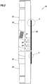
- FIG. 2 an enlarged detailed view of the well screen 12 is representatively illustrated. In this view, the construction of the well screen 12 may be conveniently seen.
- the screen 12 includes a perforated base pipe 20. Opposite longitudinal ends of the base pipe 20 are preferably provided with threads for interconnecting the well screen 12 in the tubular string 14, but other connection means may be used, if desired.
- the jacket 22 Surrounding the base pipe 20 is a screen jacket 22.
- the jacket 22 is used to filter the fluid flowing from the exterior to the interior of the screen 12.
- the jacket 22 includes multiple layers of material, examples of which are depicted in FIGS. 3-4F and described below.
- the jacket 22 is expanded radially outward prior to being positioned on the base pipe 20. After positioning the jacket 22 appropriately overlying perforations 24 through the base pipe 20, the opposite longitudinal ends of the jacket 22 are crimped onto the base pipe, and then the ends of the jacket are welded to the base pipe. This process is described more fully below.
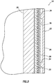
- FIG. 3 an enlarged scale cross-sectional view of a portion of the well screen 12 is representatively illustrated.
- the various layers making up the screen jacket 22, and their relationship to the base pipe 20 may be more clearly seen.
- the screen jacket 22 includes an outer shroud 26, a wire mesh filter layer 28 and an inner wire wrap drainage layer 30.
- Each of these layers performs at least one specific important function in the jacket 22, but it should be clearly understood that the principles of this disclosure are not limited to use of any particular layer or combination of layers in a screen jacket.
- the outer shroud 26 serves to protect the screen jacket 22 during installation of the well screen 12, during operations such as gravel packing, etc.
- the outer shroud 26 is made of a helically wrapped perforated stainless steel material, which is provided with unperforated tubular end rings 32 at its opposite ends (see FIG. 5A ).
- the filter layer 28 serves as the filtering element which excludes sand, formation fines, etc. from passing through the screen jacket 22.
- the filter layer 28 is made of a relatively fine stainless steel wire mesh or woven wire.
- the drainage layer 30 serves as an interface between the filter layer 28 and the base pipe 20, providing flow paths for fluid exiting the filter layer to flow into the perforations 24 of the base pipe, and providing outward support for the filter layer.
- the drainage layer 30 is made of stainless steel wire closely wrapped helically about multiple longitudinally extending stainless steel stays or rods.
- the outer shroud 26 has multiple inwardly extending dimples or protrusions 34 on its inner surface 36. These protrusions 34 provide radial space about the filter layer 28, so that the fluid can readily flow between the perforated portions of the outer shroud 26 and the outer surface of the filter layer.
- the filter layer 28 appears in FIG. 3 to be made up of multiple layers. This is due to the fact that there is an overlap between circumferential ends of the filter layer 28 in the area depicted in FIG. 3 .
- an initially flat rectangle of the filter layer 28 is rolled into a tubular shape, with an overlap between its circumferential ends. This overlap serves to prevent migration of sand or other debris through the filter layer 28, without requiring the circumferential ends to be welded or brazed together.
- the screen jacket 22 has a relatively small radial thickness, with the filter layer 28 in intimate contact with the protrusions 34 on the inner surface 36 of the outer shroud 26, with intimate contact between the filter layer and the drainage layer 30, and with minimal radial clearance between the screen jacket and the base pipe 20.
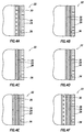
- FIGS. 4A-F various different constructions of the screen jacket 22 are representatively illustrated. These additional examples of the screen jacket 22 construction demonstrate that the principles of this disclosure are not limited to any one type of jacket construction.
- the jacket 22 is very similar to the construction of FIG. 3 , except that there are no protrusions 34 on the inner surface 36 of the outer shroud 26.
- the various jacket 22 constructions described in this disclosure may or not be provided with the protrusions 34, as desired.
- the drainage layer 30 is preferably made of a relatively coarse stainless steel welded wire mesh.
- the drainage layer 30 is preferably made of a perforated stainless steel tube, which may be similar in construction to the outer shroud 26 (e.g., helically formed and/or with unperforated end rings at each longitudinal end, etc.).
- the screen jacket 22 is very similar to the construction of FIG. 4B , except that the drainage layer 30 is preferably made of a relatively coarse stainless steel pre-crimped wire mesh, which is not necessarily welded.
- FIG. 4E two filter layers 28, 38 are used, with the outer filter layer 38 preferably being made of a relatively coarse stainless steel unwelded wire mesh or woven wire, and with the inner filter layer 28 preferably being made of a relatively fine stainless steel unwelded wire mesh or woven wire.
- the screen jacket 22 of FIG. 4F is similar to the construction of FIG. 4E , except that the drainage layer 30 is preferably made of a wire wrap instead of a perforated tube.
- FIGS. 4A-F there appears to be radial space between each of the layers in the screen jacket 22. These radial spaces may exist prior to expanding the jacket 22, but preferably after the expansion process there is no radial space between the layers, thus providing for a radially compact construction.
- FIGS. 5A & B examples of techniques for securing the screen jacket 22 to the base pipe 20 are representatively illustrated.
- the opposite longitudinal ends of the jacket 22 are crimped radially inwardly onto the base pipe 20, and then the ends of the jacket are welded to the base pipe, but it should be clearly understood that other techniques for securing the jacket to the base pipe may be used as desired.
- the screen jacket 22 is similar to that depicted in FIG. 4C .
- the drainage layer 30 has a tubular unperforated end ring 40 at each of its opposite longitudinal ends, similar to the end rings 32 on the outer shroud 26.
- the end rings 32, 40 and the filter layer 28 are the specific elements which are welded to the base pipe.
- the outer shroud 26 is not provided with the end rings 32, and the jacket 22 is similar to that depicted in FIG. 4E .
- This example demonstrates that the end rings 32, 40 are not necessarily provided in the screen jacket 22, and that any configuration of the jacket may be used in keeping with the principles of this disclosure.
- the crimping operation preferably seals the ends of the screen jacket 22 against sand migration and secures the jacket to the base pipe 20, so that welding is not strictly necessary.
- the crimping of the filter layer 28 between the outer shroud 26 and drainage layer 30 prevents migration of sand or other debris longitudinally between the layers, without the need for welding.
- the crimping operation is performed without inducing substantially increased levels of stress and strain in the layers of the screen jacket 22, and particularly so in the filter layer 28.
- a crimping tool 42 which may be used to satisfactorily perform the crimping operation is representatively illustrated.
- the crimping tool 42 is positioned on the ends of the screen jacket 22 in succession after the jacket is appropriately positioned on the base pipe 20. Pressure applied via a connector 44 biases a piston 46 downward as viewed in FIG. 6 , thereby downwardly displacing an internally tapered collet housing 48.
- This downward displacement of the collet housing 48 causes segmented collets 50 to displace radially inward. With the collets 50 positioned radially outward of the end of the screen jacket 22, this inward displacement of the collets will cause the end of the screen jacket to be crimped radially inward.
- the described examples provide a well screen system 10 which is radially compact, free of undesirable stress and strain concentrations in its filter layer(s), resistant to erosion, free of welding and brazing in its filtering portion, convenient and economical to manufacture, mechanically strengthened, and which has enhanced sand filtering capabilities.
- the above disclosure provides a method of manufacturing a well screen 12 which includes the steps of: securing a screen jacket 22 onto a base pipe 20, and, prior to the securing step: forming the screen jacket 22 comprising an outer shroud 26 and a generally tubular filter layer 28 having an overlap between circumferential ends of the filter layer 28; and radially expanding the filter layer 28 within the outer shroud 26, wherein the overlap serves to prevent sand migration through the filter layer.
- the expanding step includes expanding the filter layer 28 of the screen jacket 22 outward into contact with the outer shroud 26.
- the expanding step includes expanding the outer shroud 26.
- the securing step may include crimping one or more ends of the screen jacket 22 onto the base pipe 20.
- the crimping step may include preventing sand migration through a filter layer 28 of the screen jacket 22 at the one or more ends of the screen jacket. A substantial portion of the screen jacket 22 between the one or more ends may remain uncrimped after the crimping step.
- the securing step may include welding the screen jacket 22 to the base pipe 20 at the one or more ends of the screen jacket, and the welding step may include welding to the base pipe 20 an unperforated end ring 32, 40 of at least one of an inner drainage layer 30 and outer shroud 26 of the screen jacket 22.
- the welding step may also, or alternatively, include welding to the base pipe 20 a perforated end of at least one of the inner drainage layer 30 and outer shroud 26 of the screen jacket 22.
- the well screen system 10 which includes a base pipe 20 and an at least partially expanded screen jacket 22 surrounding the base pipe.
- the screen jacket 22 is expanded prior to being positioned on the base pipe 20.
- the base pipe 20 may be unexpanded when the expanded screen jacket 22 is positioned on the base pipe.
- At least one end of the screen jacket 22 is crimped onto the base pipe 20.
- a substantial portion of the screen jacket 22 may be uncrimped.
- a crimp at an end of the screen jacket 22 may exclude sand from migrating through a filter layer 28 of the screen jacket at the crimp.
- An outer shroud 26 of the screen jacket 26 may be perforated at the crimped end of the screen jacket.
- the filter layer 28 may contact the outer shroud 26 due to expansion of the screen jacket 22.
- the outer shroud 26 is expanded when the screen jacket 22 is positioned on the base pipe 20.
- the screen jacket 22 may not be welded to the base pipe 20 during sand-screening use of the well screen system 10.
Description
- The present disclosure relates generally to equipment utilized and operations performed in conjunction with a subterranean well.
- Well screens are typically used to exclude sand and formation fines from fluids produced from subterranean wells. Where wire mesh is used as a filter layer in a well screen, it has been found that bonding operations (such as welding and brazing) performed on the wire mesh are detrimental to the long-term usefulness of the wire mesh. For example, the wire mesh may be thus made more susceptible to erosion.
- An attempt has been made to address the problems associated with a bonded wire mesh filter layer by swaging an entire screen jacket including the filter layer onto a base pipe. An overlap in a wrap of the wire mesh filter layer is used instead of welding to seal the filter layer against sand migration. However, this method of swaging the screen jacket also imparts undesirable stress concentrations in the filter layer, which can lead to premature failure.
- Prior art document
US 2004/0003927 A1 discloses a well screen and a method of manufacturing a well screen. -
GB 2 364 727 A -
CN 1 888 379 discloses a well screen and a method of manufacturing a well screen as recited in the preamble of the appended independent claim. - Therefore, it will be appreciated that improvements are needed in the art of constructing well screens. These improvements may find use in well screens which either do or do not have wire mesh filter layers.
- In the present specification, systems and methods are provided which solve at least one problem in the art. One example is described below in which a screen jacket is expanded radially outward before being attached to a base pipe. Another example is described below in which sand migration through longitudinal ends of the screen jacket is prevented using crimps at the ends of the screen jacket.
- According to the invention there is provided a method of manufacturing a well screen, the method comprising the step of securing a screen jacket onto a base pipe, characterised by, prior to the securing step: forming the screen jacket, wherein forming the screen jacket comprises installing a tubular filter layer into the interior of an outer shroud, the tubular filter layer having an overlap between circumferential ends of the filter layer; installing a drainage layer into the interior of the tubular filter layer; and radially expanding the drainage layer and the filter layer of the screen jacket outward within the outer shroud until the filter layer contacts an inner surface of the outer shroud, and until all of the layers are in intimate contact with their adjacent layer or layers; wherein the expanding step further comprises expanding the outer shroud ; and the overlap serves to prevent sand migration through the filter layer.
- The securing step may include crimping one or more longitudinal ends of the screen jacket onto the base pipe. The crimping step may include preventing sand migration through the filter layer of the screen jacket at the one or more longitudinal ends of the screen jacket. A substantial portion of the screen jacket between the one or more longitudinal ends may remain uncrimped after the crimping step.
- The securing step may include welding the screen jacket to the base pipe at the one or more longitudinal ends of the screen jacket, and the welding step may include welding to the base pipe an unperforated end ring of at least one of the inner drainage layer and the outer shroud of the screen jacket. The welding step may alternatively, include welding to the base pipe a perforated end of at least one of the inner drainage layer and outer shroud of the screen jacket.
- Herein disclosed is a well screen system manufactured according to the methods described.
- The described examples provide a well screen system which is: 1) radially compact, 2) free of undesirable stress and strain concentrations in its filter layer(s), 3) resistant to erosion, 4) free of welding and brazing in its filtering portion, 5) convenient and economical to manufacture, 6) mechanically strengthened, and 7) which has enhanced sand filtering capabilities.
- These and other features, advantages, benefits and objects will become apparent to one of ordinary skill in the art upon careful consideration of the detailed description of representative embodiments hereinbelow and the accompanying drawings, in which similar elements are indicated in the various figures using the same reference numbers.
-
FIG. 1 is a schematic partially cross-sectional view of a well system; -
FIG. 2 is an enlarged scale cross-sectional view through a well screen system usable in the well system ofFIG. 1 ; -
FIG. 3 is a further enlarged scale cross-sectional view of a screen jacket and base pipe of the well screen system; -
FIGS. 4A-F are schematic cross-sectional views of additional screen jacket constructions which may be used in the well screen system; -
FIGS. 5A &B are schematic cross-sectional views of techniques for securing the screen jacket to the base pipe; and -
FIG. 6 is a partially cross-sectional view of a crimping tool usable in the securing techniques ofFIGS. 5A &B . - It is to be understood that the various embodiments described herein may be utilized in various orientations, such as inclined, inverted, horizontal, vertical, etc., and in various configurations, without departing from the principles of the present disclosure. The embodiments are described merely as examples of useful applications of the principles of the disclosure, which are not limited to any specific details of these embodiments.
- In the following description of the representative embodiments of the disclosure, directional terms, such as "above", "below", "upper", "lower", etc., are used for convenience in referring to the accompanying drawings.
- Representatively illustrated in
FIG. 1 is awell screen system 10. As depicted inFIG. 1 , a wellscreen 12 has been interconnected in a tubular string 14 (such as a liner string or a production tubing string) and positioned in awellbore 16. The well screen 12 filters sand and formation fines out of fluid flowing from aformation 18 into thetubular string 14. - The methods of manufacturing the well
screen 12 as described below provide many advancements in the art. However, it should be clearly understood that the principles of this disclosure are not limited in any way to the details illustrated inFIG. 1 . For example, thewellbore 16 could be uncased or open hole, thescreen 12 could be gravel packed, etc. - Referring additionally now to
FIG. 2 , an enlarged detailed view of thewell screen 12 is representatively illustrated. In this view, the construction of the wellscreen 12 may be conveniently seen. - The
screen 12 includes aperforated base pipe 20. Opposite longitudinal ends of thebase pipe 20 are preferably provided with threads for interconnecting thewell screen 12 in thetubular string 14, but other connection means may be used, if desired. - Surrounding the
base pipe 20 is ascreen jacket 22. Thejacket 22 is used to filter the fluid flowing from the exterior to the interior of thescreen 12. Thejacket 22 includes multiple layers of material, examples of which are depicted inFIGS. 3-4F and described below. - In one unique feature of the
screen 12, thejacket 22 is expanded radially outward prior to being positioned on thebase pipe 20. After positioning thejacket 22 appropriately overlyingperforations 24 through thebase pipe 20, the opposite longitudinal ends of thejacket 22 are crimped onto the base pipe, and then the ends of the jacket are welded to the base pipe. This process is described more fully below. - Referring additionally now to
FIG. 3 , an enlarged scale cross-sectional view of a portion of thewell screen 12 is representatively illustrated. In this view, the various layers making up thescreen jacket 22, and their relationship to thebase pipe 20 may be more clearly seen. - In the example of
FIG. 3 , thescreen jacket 22 includes anouter shroud 26, a wiremesh filter layer 28 and an inner wirewrap drainage layer 30. Each of these layers performs at least one specific important function in thejacket 22, but it should be clearly understood that the principles of this disclosure are not limited to use of any particular layer or combination of layers in a screen jacket. - The
outer shroud 26 serves to protect thescreen jacket 22 during installation of the wellscreen 12, during operations such as gravel packing, etc. Preferably, theouter shroud 26 is made of a helically wrapped perforated stainless steel material, which is provided with unperforatedtubular end rings 32 at its opposite ends (seeFIG. 5A ). - The
filter layer 28 serves as the filtering element which excludes sand, formation fines, etc. from passing through thescreen jacket 22. Preferably, thefilter layer 28 is made of a relatively fine stainless steel wire mesh or woven wire. - The
drainage layer 30 serves as an interface between thefilter layer 28 and thebase pipe 20, providing flow paths for fluid exiting the filter layer to flow into theperforations 24 of the base pipe, and providing outward support for the filter layer. Preferably, thedrainage layer 30 is made of stainless steel wire closely wrapped helically about multiple longitudinally extending stainless steel stays or rods. - Note that, in this example, the
outer shroud 26 has multiple inwardly extending dimples orprotrusions 34 on itsinner surface 36. Theseprotrusions 34 provide radial space about thefilter layer 28, so that the fluid can readily flow between the perforated portions of theouter shroud 26 and the outer surface of the filter layer. - In addition, note that the
filter layer 28 appears inFIG. 3 to be made up of multiple layers. This is due to the fact that there is an overlap between circumferential ends of thefilter layer 28 in the area depicted inFIG. 3 . - When constructing the
screen jacket 22, an initially flat rectangle of thefilter layer 28 is rolled into a tubular shape, with an overlap between its circumferential ends. This overlap serves to prevent migration of sand or other debris through thefilter layer 28, without requiring the circumferential ends to be welded or brazed together. - Note, also, that the
screen jacket 22 has a relatively small radial thickness, with thefilter layer 28 in intimate contact with theprotrusions 34 on theinner surface 36 of theouter shroud 26, with intimate contact between the filter layer and thedrainage layer 30, and with minimal radial clearance between the screen jacket and thebase pipe 20. These desirable features are achieved as a result of the unique construction process described below, in which the filter anddrainage layers outer shroud 26 prior to positioning thescreen jacket 22 on thebase pipe 20. - Referring additionally now to
FIGS. 4A-F , various different constructions of thescreen jacket 22 are representatively illustrated. These additional examples of thescreen jacket 22 construction demonstrate that the principles of this disclosure are not limited to any one type of jacket construction. - In
FIG. 4A , thejacket 22 is very similar to the construction ofFIG. 3 , except that there are noprotrusions 34 on theinner surface 36 of theouter shroud 26. Thevarious jacket 22 constructions described in this disclosure may or not be provided with theprotrusions 34, as desired. - In
FIG. 4B , thedrainage layer 30 is preferably made of a relatively coarse stainless steel welded wire mesh. InFIG. 4C , thedrainage layer 30 is preferably made of a perforated stainless steel tube, which may be similar in construction to the outer shroud 26 (e.g., helically formed and/or with unperforated end rings at each longitudinal end, etc.). InFIG. 4D , thescreen jacket 22 is very similar to the construction ofFIG. 4B , except that thedrainage layer 30 is preferably made of a relatively coarse stainless steel pre-crimped wire mesh, which is not necessarily welded. These examples demonstrate that various types of drainage layers may be used in keeping with the principles of this disclosure. - In
FIG. 4E , twofilter layers outer filter layer 38 preferably being made of a relatively coarse stainless steel unwelded wire mesh or woven wire, and with theinner filter layer 28 preferably being made of a relatively fine stainless steel unwelded wire mesh or woven wire. Thescreen jacket 22 ofFIG. 4F is similar to the construction ofFIG. 4E , except that thedrainage layer 30 is preferably made of a wire wrap instead of a perforated tube. These examples demonstrate that any number and combination of the layers may be used in keeping with the principles of this disclosure. - Note that in
FIGS. 4A-F there appears to be radial space between each of the layers in thescreen jacket 22. These radial spaces may exist prior to expanding thejacket 22, but preferably after the expansion process there is no radial space between the layers, thus providing for a radially compact construction. - Referring additionally now to
FIGS. 5A &B , examples of techniques for securing thescreen jacket 22 to thebase pipe 20 are representatively illustrated. In each of these, the opposite longitudinal ends of thejacket 22 are crimped radially inwardly onto thebase pipe 20, and then the ends of the jacket are welded to the base pipe, but it should be clearly understood that other techniques for securing the jacket to the base pipe may be used as desired. - In
FIG. 5A , thescreen jacket 22 is similar to that depicted inFIG. 4C . Thedrainage layer 30 has a tubularunperforated end ring 40 at each of its opposite longitudinal ends, similar to the end rings 32 on theouter shroud 26. When thejacket 22 is welded to thebase pipe 20, the end rings 32, 40 and thefilter layer 28 are the specific elements which are welded to the base pipe. - In
FIG. 5B , theouter shroud 26 is not provided with the end rings 32, and thejacket 22 is similar to that depicted inFIG. 4E . This example demonstrates that the end rings 32, 40 are not necessarily provided in thescreen jacket 22, and that any configuration of the jacket may be used in keeping with the principles of this disclosure. - Note that it is not necessary to weld the
screen jacket 22 to thebase pipe 20 if the crimping operations are properly performed. The crimping operation preferably seals the ends of thescreen jacket 22 against sand migration and secures the jacket to thebase pipe 20, so that welding is not strictly necessary. For example, it will be appreciated that in the configuration ofFIG. 5A , the crimping of thefilter layer 28 between theouter shroud 26 anddrainage layer 30 prevents migration of sand or other debris longitudinally between the layers, without the need for welding. - Preferably, the crimping operation is performed without inducing substantially increased levels of stress and strain in the layers of the
screen jacket 22, and particularly so in thefilter layer 28. InFIG. 6 , a crimpingtool 42 which may be used to satisfactorily perform the crimping operation is representatively illustrated. - The crimping
tool 42 is positioned on the ends of thescreen jacket 22 in succession after the jacket is appropriately positioned on thebase pipe 20. Pressure applied via aconnector 44 biases apiston 46 downward as viewed inFIG. 6 , thereby downwardly displacing an internally taperedcollet housing 48. - This downward displacement of the
collet housing 48 causes segmentedcollets 50 to displace radially inward. With thecollets 50 positioned radially outward of the end of thescreen jacket 22, this inward displacement of the collets will cause the end of the screen jacket to be crimped radially inward. -
Shoulders 52 on thecollets 50 are radiused to prevent causing significant stress concentrations in the area between the crimped and uncrimped portions of thejacket 22 ends. Pressure may then be applied via anotherconnector 54 to upwardly displace thepiston 46 andcollet housing 48, thereby allowing thecollets 50 to spring back radially outward. - In a preferred method of constructing the
well screen 12, the following steps are performed in the listed order: - 1) The filter layer 28 (e.g., a wire mesh) is conditioned by rolling it into a tubular shape.
- 2) Circumferential ends of the
filter layer 28 are overlapped. - 3) The
filter layer 28 is installed into the interior of theouter shroud 26. - 4) The
drainage layer 30 is installed into the interior of the filter layer. - 5) The
drainage layer 30 andfilter layer 28 are expanded radially outward at least until the filter layer contacts theinner surface 36 of theouter shroud 26, and all of the layers are in intimate contact with their adjacent layer(s). Further expansion is used to radially outwardly expand theouter shroud 26, which may be useful to "size" the outer shroud, for example, to compensate for manufacturing tolerances. The expansion process may be accomplished by drawing, pushing or otherwise forcing a conical drift or mandrel through the interior of thedrainage layer 30, by pressurizing an inflatable bladder or membrane within thejacket 22, or by any other expansion technique. Before the expansion step, thejacket 22 has an interior dimension (e.g., an ID) less than an exterior dimension (e.g., an OD) of thebase pipe 20, but after the expansion step, the jacket interior dimension is equal to or greater than the exterior dimension of the base pipe. - 6) The expanded
screen jacket 22 is positioned on thebase pipe 20. - 7) The ends of the
screen jacket 22 are crimped onto thebase pipe 20. - 8) The ends of the
screen jacket 22 are welded to thebase pipe 20. - It may now be fully appreciated that the above disclosure provides many advancements to the art of constructing well screens. In particular, the described examples provide a
well screen system 10 which is radially compact, free of undesirable stress and strain concentrations in its filter layer(s), resistant to erosion, free of welding and brazing in its filtering portion, convenient and economical to manufacture, mechanically strengthened, and which has enhanced sand filtering capabilities. - The above disclosure provides a method of manufacturing a
well screen 12 which includes the steps of: securing ascreen jacket 22 onto abase pipe 20, and, prior to the securing step: forming thescreen jacket 22 comprising anouter shroud 26 and a generallytubular filter layer 28 having an overlap between circumferential ends of thefilter layer 28; and radially expanding thefilter layer 28 within theouter shroud 26, wherein the overlap serves to prevent sand migration through the filter layer. The expanding step includes expanding thefilter layer 28 of thescreen jacket 22 outward into contact with theouter shroud 26. The expanding step includes expanding theouter shroud 26. - The securing step may include crimping one or more ends of the
screen jacket 22 onto thebase pipe 20. The crimping step may include preventing sand migration through afilter layer 28 of thescreen jacket 22 at the one or more ends of the screen jacket. A substantial portion of thescreen jacket 22 between the one or more ends may remain uncrimped after the crimping step. - The securing step may include welding the
screen jacket 22 to thebase pipe 20 at the one or more ends of the screen jacket, and the welding step may include welding to thebase pipe 20 anunperforated end ring inner drainage layer 30 andouter shroud 26 of thescreen jacket 22. The welding step may also, or alternatively, include welding to the base pipe 20 a perforated end of at least one of theinner drainage layer 30 andouter shroud 26 of thescreen jacket 22. - Also herein disclosed is the
well screen system 10 which includes abase pipe 20 and an at least partially expandedscreen jacket 22 surrounding the base pipe. Thescreen jacket 22 is expanded prior to being positioned on thebase pipe 20. - The
base pipe 20 may be unexpanded when the expandedscreen jacket 22 is positioned on the base pipe. - At least one end of the
screen jacket 22 is crimped onto thebase pipe 20. A substantial portion of thescreen jacket 22 may be uncrimped. A crimp at an end of thescreen jacket 22 may exclude sand from migrating through afilter layer 28 of the screen jacket at the crimp. Anouter shroud 26 of thescreen jacket 26 may be perforated at the crimped end of the screen jacket. - The
filter layer 28 may contact theouter shroud 26 due to expansion of thescreen jacket 22. Theouter shroud 26 is expanded when thescreen jacket 22 is positioned on thebase pipe 20. - The
screen jacket 22 may not be welded to thebase pipe 20 during sand-screening use of thewell screen system 10. - Of course, a person skilled in the art would, upon a careful consideration of the above description of representative embodiments, readily appreciate that many modifications, additions, substitutions, deletions, and other changes may be made to these specific embodiments, as long as said modifications, additions, substitutions, deletions and other changes are within the scope as set by the appended claims.
Claims (7)
- A method of manufacturing a well screen (12), the method comprising the step of securing a screen jacket (22) onto a base pipe (20), wherein, prior to the securing step, the method comprises the steps of:forming the screen jacket (22), wherein forming the screen jacket (22) comprises installing a tubular filter layer (28) into the interior of an outer shroud (26), the tubular filter layer (28) having an overlap between circumferential ends of the filter layer (28);installing a drainage layer (30) into the interior of the tubular filter layer (28); andradially expanding the drainage layer (30) and the filter layer (28) of the screen jacket (22) outward within the outer shroud (26) until the filter layer contacts an inner surface of the outer shroud, and until all of the layers are in intimate contact with their adjacent layer or layers; wherein:the overlap serves to prevent sand migration through the filter layer (28),characterized in that the expanding step further comprises expanding the outer shroud (26).
- The method of claim 1, wherein the securing step further comprises crimping one or more longitudinal ends of the screen jacket (22) onto the base pipe (20).
- The method of claim 2, wherein the crimping step further comprises preventing sand migration through the filter layer (28) of the screen jacket (22) at the one or more longitudinal ends of the screen jacket (22).
- The method of claim 2, wherein the securing step further comprises welding the screen jacket (22) to the base pipe (20) at the one or more longitudinal ends of the screen jacket (22), and wherein the welding step further comprises welding to the base pipe (20) an unperforated end ring (32, 40) of at least one of the drainage layer (30) and the outer shroud (26) of the screen jacket (22).
- The method of claim 2, wherein the securing step further comprises welding the screen jacket (22) to the base pipe (20) at the one or more longitudinal ends of the screen jacket (22), and wherein the welding step further comprises welding to the base pipe (20) a perforated end of at least one of the drainage layer (30) and outer shroud (26) of the screen jacket (22).
- A method as claimed in any preceding claim, wherein the filter layer (28) is a one piece filter layer.
- A method as claimed in any one of claims 2, 3, 4 or 5 wherein a substantial portion of the screen jacket (22) remains uncrimped between the one or more longitudinal ends of the screen jacket (22) after the crimping step.
Applications Claiming Priority (1)
| Application Number | Priority Date | Filing Date | Title |
|---|---|---|---|
| US12/166,966 US8176634B2 (en) | 2008-07-02 | 2008-07-02 | Method of manufacturing a well screen |
Publications (3)
| Publication Number | Publication Date |
|---|---|
| EP2141323A2 EP2141323A2 (en) | 2010-01-06 |
| EP2141323A3 EP2141323A3 (en) | 2012-12-26 |
| EP2141323B1 true EP2141323B1 (en) | 2020-11-25 |
Family
ID=41228663
Family Applications (1)
| Application Number | Title | Priority Date | Filing Date |
|---|---|---|---|
| EP09164282.7A Active EP2141323B1 (en) | 2008-07-02 | 2009-07-01 | Expanded non-bonded mesh well screen |
Country Status (7)
| Country | Link |
|---|---|
| US (2) | US8176634B2 (en) |
| EP (1) | EP2141323B1 (en) |
| CN (1) | CN101619653B (en) |
| BR (1) | BRPI0902411B1 (en) |
| MX (1) | MX2009007172A (en) |
| MY (1) | MY147553A (en) |
| SG (1) | SG158062A1 (en) |
Families Citing this family (24)
| Publication number | Priority date | Publication date | Assignee | Title |
|---|---|---|---|---|
| SG155087A1 (en) * | 2008-02-27 | 2009-09-30 | Completion Products Pte Ltd | A well screen |
| US8176634B2 (en) | 2008-07-02 | 2012-05-15 | Halliburton Energy Services, Inc. | Method of manufacturing a well screen |
| US20100258302A1 (en) * | 2009-04-08 | 2010-10-14 | Halliburton Energy Services, Inc. | Well Screen With Drainage Assembly |
| US8146662B2 (en) * | 2009-04-08 | 2012-04-03 | Halliburton Energy Services, Inc. | Well screen assembly with multi-gage wire wrapped layer |
| US8251138B2 (en) * | 2009-04-09 | 2012-08-28 | Halliburton Energy Services, Inc. | Securing layers in a well screen assembly |
| US8567498B2 (en) * | 2010-01-22 | 2013-10-29 | Schlumberger Technology Corporation | System and method for filtering sand in a wellbore |
| US8464793B2 (en) * | 2010-01-22 | 2013-06-18 | Schlumberger Technology Corporation | Flow control system with sand screen |
| US8291971B2 (en) | 2010-08-13 | 2012-10-23 | Halliburton Energy Services, Inc. | Crimped end wrapped on pipe well screen |
| CN102182430A (en) * | 2011-03-28 | 2011-09-14 | 刘春博 | Drillable quartz sand filter tube sand-prevention mated tube column of horizontal well |
| US9267360B2 (en) * | 2011-04-01 | 2016-02-23 | Schlumberger Technology Corporation | Premium mesh screen |
| AP2014007665A0 (en) * | 2011-12-21 | 2014-05-31 | Linc Energy Ltd | Underground coal gasification well liner |
| US20150267510A1 (en) * | 2012-10-26 | 2015-09-24 | Halliburton Energy Services, Inc. | Well Screen and Method of Manufacturing |
| AU2013381050B2 (en) * | 2013-03-06 | 2016-07-07 | Halliburton Energy Services, Inc. | Method of assembly for sand screen |
| US20160024897A1 (en) | 2013-04-01 | 2016-01-28 | Stephen Michael Greci | Well Screen Assembly with Extending Screen |
| WO2015057199A1 (en) * | 2013-10-15 | 2015-04-23 | Halliburton Energy Services, Inc. | Erosion resistant screen assembly |
| GB201323121D0 (en) | 2013-12-30 | 2014-02-12 | Darcy Technologies Ltd | Downhole Apparatus |
| RU2610964C1 (en) * | 2016-01-11 | 2017-02-17 | Акционерное общество "Новомет-Пермь" | Well strainer |
| US10767449B2 (en) * | 2016-06-15 | 2020-09-08 | Chevron U.S.A. Inc. | Protective shrouds for sand control screen assemblies |
| US10781672B2 (en) * | 2016-06-15 | 2020-09-22 | Chevron U.S.A. Inc. | Protective shrouds for sand control screen assemblies |
| WO2018031775A1 (en) | 2016-08-12 | 2018-02-15 | Baker Hughes, A Ge Company, Llc | Magnetic pulse actuation arrangement for downhole tools and method |
| US11014191B2 (en) | 2016-08-12 | 2021-05-25 | Baker Hughes, A Ge Company, Llc | Frequency modulation for magnetic pressure pulse tool |
| US10626705B2 (en) | 2018-02-09 | 2020-04-21 | Baer Hughes, A Ge Company, Llc | Magnetic pulse actuation arrangement having layer and method |
| US10914141B2 (en) * | 2018-03-08 | 2021-02-09 | Baker Hughes, A Ge Company, Llc | Screen jacket termination configuration and method |
| GB2595146B (en) | 2019-02-20 | 2023-07-12 | Schlumberger Technology Bv | Non-metallic compliant sand control screen |
Citations (3)
| Publication number | Priority date | Publication date | Assignee | Title |
|---|---|---|---|---|
| GB2364727A (en) * | 1999-05-28 | 2002-02-06 | Baker Hughes Inc | Running a screen downhole |
| US20040026313A1 (en) * | 2002-08-09 | 2004-02-12 | Arlon Fischer Todd Kenneth | Multi-micron, multi-zoned mesh, method of making and use thereof |
| CN1888379A (en) * | 2006-07-15 | 2007-01-03 | 易会安 | Sandproof integrated compound screening pipe and processing method thereof |
Family Cites Families (13)
| Publication number | Priority date | Publication date | Assignee | Title |
|---|---|---|---|---|
| US5624560A (en) * | 1995-04-07 | 1997-04-29 | Baker Hughes Incorporated | Wire mesh filter including a protective jacket |
| US5611399A (en) * | 1995-11-13 | 1997-03-18 | Baker Hughes Incorporated | Screen and method of manufacturing |
| US6263966B1 (en) * | 1998-11-16 | 2001-07-24 | Halliburton Energy Services, Inc. | Expandable well screen |
| US6305468B1 (en) * | 1999-05-28 | 2001-10-23 | Baker Hughes Incorporated | Downhole screen and method of manufacture |
| US6457518B1 (en) * | 2000-05-05 | 2002-10-01 | Halliburton Energy Services, Inc. | Expandable well screen |
| AU781921B2 (en) * | 2000-09-11 | 2005-06-23 | Baker Hughes Incorporated | Multi layer screen and downhole completion method |
| US6478092B2 (en) * | 2000-09-11 | 2002-11-12 | Baker Hughes Incorporated | Well completion method and apparatus |
| US7168485B2 (en) * | 2001-01-16 | 2007-01-30 | Schlumberger Technology Corporation | Expandable systems that facilitate desired fluid flow |
| GB0111779D0 (en) * | 2001-05-15 | 2001-07-04 | Weatherford Lamb | Expanding tubing |
| GB0209472D0 (en) * | 2002-04-25 | 2002-06-05 | Weatherford Lamb | Expandable downhole tubular |
| US7497257B2 (en) * | 2006-05-04 | 2009-03-03 | Purolator Facet, Inc. | Particle control screen with depth filtration |
| CN201050353Y (en) * | 2007-05-29 | 2008-04-23 | 辽宁跨克石油装备有限公司 | High-intensity highly effective filtering sand controller |
| US8176634B2 (en) | 2008-07-02 | 2012-05-15 | Halliburton Energy Services, Inc. | Method of manufacturing a well screen |
-
2008
- 2008-07-02 US US12/166,966 patent/US8176634B2/en active Active
-
2009
- 2009-06-30 SG SG200904453-8A patent/SG158062A1/en unknown
- 2009-06-30 MY MYPI20092782A patent/MY147553A/en unknown
- 2009-07-01 MX MX2009007172A patent/MX2009007172A/en active IP Right Grant
- 2009-07-01 EP EP09164282.7A patent/EP2141323B1/en active Active
- 2009-07-02 CN CN2009101513672A patent/CN101619653B/en active Active
- 2009-07-02 BR BRPI0902411A patent/BRPI0902411B1/en active IP Right Grant
-
2012
- 2012-02-15 US US13/397,011 patent/US8850706B2/en active Active
Patent Citations (3)
| Publication number | Priority date | Publication date | Assignee | Title |
|---|---|---|---|---|
| GB2364727A (en) * | 1999-05-28 | 2002-02-06 | Baker Hughes Inc | Running a screen downhole |
| US20040026313A1 (en) * | 2002-08-09 | 2004-02-12 | Arlon Fischer Todd Kenneth | Multi-micron, multi-zoned mesh, method of making and use thereof |
| CN1888379A (en) * | 2006-07-15 | 2007-01-03 | 易会安 | Sandproof integrated compound screening pipe and processing method thereof |
Also Published As
| Publication number | Publication date |
|---|---|
| US20120138287A1 (en) | 2012-06-07 |
| SG158062A1 (en) | 2010-01-29 |
| US20100000742A1 (en) | 2010-01-07 |
| MX2009007172A (en) | 2010-03-01 |
| BRPI0902411A2 (en) | 2011-08-30 |
| CN101619653A (en) | 2010-01-06 |
| EP2141323A3 (en) | 2012-12-26 |
| CN101619653B (en) | 2013-10-16 |
| US8850706B2 (en) | 2014-10-07 |
| BRPI0902411B1 (en) | 2018-12-18 |
| MY147553A (en) | 2012-12-31 |
| EP2141323A2 (en) | 2010-01-06 |
| US8176634B2 (en) | 2012-05-15 |
Similar Documents
| Publication | Publication Date | Title |
|---|---|---|
| EP2141323B1 (en) | Expanded non-bonded mesh well screen | |
| CA2538112C (en) | Multi-layer screen and downhole completion method | |
| US7134501B2 (en) | Expandable sand screen and methods for use | |
| AU773398B2 (en) | Expandable well screen | |
| CA2900455C (en) | Method of assembly for sand screen | |
| CA2817581C (en) | Sand control screen assembly having a compliant drainage layer | |
| US6612481B2 (en) | Wellscreen | |
| US20120073801A1 (en) | Sand Control Screen Assembly Having a Mechanically Attached Screen Jacket | |
| CA2544643C (en) | Expandable sand screen and methods for use | |
| CA2367859C (en) | Expandable sand screen and methods for use |
Legal Events
| Date | Code | Title | Description |
|---|---|---|---|
| PUAI | Public reference made under article 153(3) epc to a published international application that has entered the european phase |
Free format text: ORIGINAL CODE: 0009012 |
|
| AK | Designated contracting states |
Kind code of ref document: A2 Designated state(s): AT BE BG CH CY CZ DE DK EE ES FI FR GB GR HR HU IE IS IT LI LT LU LV MC MK MT NL NO PL PT RO SE SI SK SM TR |
|
| PUAL | Search report despatched |
Free format text: ORIGINAL CODE: 0009013 |
|
| AK | Designated contracting states |
Kind code of ref document: A3 Designated state(s): AT BE BG CH CY CZ DE DK EE ES FI FR GB GR HR HU IE IS IT LI LT LU LV MC MK MT NL NO PL PT RO SE SI SK SM TR |
|
| AX | Request for extension of the european patent |
Extension state: AL BA RS |
|
| RIC1 | Information provided on ipc code assigned before grant |
Ipc: E21B 43/08 20060101AFI20121121BHEP |
|
| 17P | Request for examination filed |
Effective date: 20130619 |
|
| RBV | Designated contracting states (corrected) |
Designated state(s): AT BE BG CH CY CZ DE DK EE ES FI FR GB GR HR HU IE IS IT LI LT LU LV MC MK MT NL NO PL PT RO SE SI SK SM TR |
|
| STAA | Information on the status of an ep patent application or granted ep patent |
Free format text: STATUS: EXAMINATION IS IN PROGRESS |
|
| 17Q | First examination report despatched |
Effective date: 20170102 |
|
| RAP1 | Party data changed (applicant data changed or rights of an application transferred) |
Owner name: HALLIBURTON ENERGY SERVICES INC. |
|
| GRAP | Despatch of communication of intention to grant a patent |
Free format text: ORIGINAL CODE: EPIDOSNIGR1 |
|
| STAA | Information on the status of an ep patent application or granted ep patent |
Free format text: STATUS: GRANT OF PATENT IS INTENDED |
|
| INTG | Intention to grant announced |
Effective date: 20200619 |
|
| GRAS | Grant fee paid |
Free format text: ORIGINAL CODE: EPIDOSNIGR3 |
|
| GRAA | (expected) grant |
Free format text: ORIGINAL CODE: 0009210 |
|
| STAA | Information on the status of an ep patent application or granted ep patent |
Free format text: STATUS: THE PATENT HAS BEEN GRANTED |
|
| AK | Designated contracting states |
Kind code of ref document: B1 Designated state(s): AT BE BG CH CY CZ DE DK EE ES FI FR GB GR HR HU IE IS IT LI LT LU LV MC MK MT NL NO PL PT RO SE SI SK SM TR |
|
| REG | Reference to a national code |
Ref country code: GB Ref legal event code: FG4D |
|
| REG | Reference to a national code |
Ref country code: CH Ref legal event code: EP |
|
| REG | Reference to a national code |
Ref country code: AT Ref legal event code: REF Ref document number: 1338514 Country of ref document: AT Kind code of ref document: T Effective date: 20201215 |
|
| REG | Reference to a national code |
Ref country code: DE Ref legal event code: R096 Ref document number: 602009063086 Country of ref document: DE |
|
| REG | Reference to a national code |
Ref country code: IE Ref legal event code: FG4D |
|
| REG | Reference to a national code |
Ref country code: NO Ref legal event code: T2 Effective date: 20201125 |
|
| REG | Reference to a national code |
Ref country code: AT Ref legal event code: MK05 Ref document number: 1338514 Country of ref document: AT Kind code of ref document: T Effective date: 20201125 |
|
| REG | Reference to a national code |
Ref country code: NL Ref legal event code: MP Effective date: 20201125 |
|
| PG25 | Lapsed in a contracting state [announced via postgrant information from national office to epo] |
Ref country code: PT Free format text: LAPSE BECAUSE OF FAILURE TO SUBMIT A TRANSLATION OF THE DESCRIPTION OR TO PAY THE FEE WITHIN THE PRESCRIBED TIME-LIMIT Effective date: 20210325 Ref country code: FI Free format text: LAPSE BECAUSE OF FAILURE TO SUBMIT A TRANSLATION OF THE DESCRIPTION OR TO PAY THE FEE WITHIN THE PRESCRIBED TIME-LIMIT Effective date: 20201125 Ref country code: GR Free format text: LAPSE BECAUSE OF FAILURE TO SUBMIT A TRANSLATION OF THE DESCRIPTION OR TO PAY THE FEE WITHIN THE PRESCRIBED TIME-LIMIT Effective date: 20210226 |
|
| PG25 | Lapsed in a contracting state [announced via postgrant information from national office to epo] |
Ref country code: PL Free format text: LAPSE BECAUSE OF FAILURE TO SUBMIT A TRANSLATION OF THE DESCRIPTION OR TO PAY THE FEE WITHIN THE PRESCRIBED TIME-LIMIT Effective date: 20201125 Ref country code: SE Free format text: LAPSE BECAUSE OF FAILURE TO SUBMIT A TRANSLATION OF THE DESCRIPTION OR TO PAY THE FEE WITHIN THE PRESCRIBED TIME-LIMIT Effective date: 20201125 Ref country code: LV Free format text: LAPSE BECAUSE OF FAILURE TO SUBMIT A TRANSLATION OF THE DESCRIPTION OR TO PAY THE FEE WITHIN THE PRESCRIBED TIME-LIMIT Effective date: 20201125 Ref country code: IS Free format text: LAPSE BECAUSE OF FAILURE TO SUBMIT A TRANSLATION OF THE DESCRIPTION OR TO PAY THE FEE WITHIN THE PRESCRIBED TIME-LIMIT Effective date: 20210325 Ref country code: BG Free format text: LAPSE BECAUSE OF FAILURE TO SUBMIT A TRANSLATION OF THE DESCRIPTION OR TO PAY THE FEE WITHIN THE PRESCRIBED TIME-LIMIT Effective date: 20210225 Ref country code: AT Free format text: LAPSE BECAUSE OF FAILURE TO SUBMIT A TRANSLATION OF THE DESCRIPTION OR TO PAY THE FEE WITHIN THE PRESCRIBED TIME-LIMIT Effective date: 20201125 |
|
| REG | Reference to a national code |
Ref country code: LT Ref legal event code: MG9D |
|
| PG25 | Lapsed in a contracting state [announced via postgrant information from national office to epo] |
Ref country code: HR Free format text: LAPSE BECAUSE OF FAILURE TO SUBMIT A TRANSLATION OF THE DESCRIPTION OR TO PAY THE FEE WITHIN THE PRESCRIBED TIME-LIMIT Effective date: 20201125 |
|
| PG25 | Lapsed in a contracting state [announced via postgrant information from national office to epo] |
Ref country code: LT Free format text: LAPSE BECAUSE OF FAILURE TO SUBMIT A TRANSLATION OF THE DESCRIPTION OR TO PAY THE FEE WITHIN THE PRESCRIBED TIME-LIMIT Effective date: 20201125 Ref country code: SM Free format text: LAPSE BECAUSE OF FAILURE TO SUBMIT A TRANSLATION OF THE DESCRIPTION OR TO PAY THE FEE WITHIN THE PRESCRIBED TIME-LIMIT Effective date: 20201125 Ref country code: RO Free format text: LAPSE BECAUSE OF FAILURE TO SUBMIT A TRANSLATION OF THE DESCRIPTION OR TO PAY THE FEE WITHIN THE PRESCRIBED TIME-LIMIT Effective date: 20201125 Ref country code: SK Free format text: LAPSE BECAUSE OF FAILURE TO SUBMIT A TRANSLATION OF THE DESCRIPTION OR TO PAY THE FEE WITHIN THE PRESCRIBED TIME-LIMIT Effective date: 20201125 Ref country code: EE Free format text: LAPSE BECAUSE OF FAILURE TO SUBMIT A TRANSLATION OF THE DESCRIPTION OR TO PAY THE FEE WITHIN THE PRESCRIBED TIME-LIMIT Effective date: 20201125 Ref country code: CZ Free format text: LAPSE BECAUSE OF FAILURE TO SUBMIT A TRANSLATION OF THE DESCRIPTION OR TO PAY THE FEE WITHIN THE PRESCRIBED TIME-LIMIT Effective date: 20201125 |
|
| REG | Reference to a national code |
Ref country code: DE Ref legal event code: R097 Ref document number: 602009063086 Country of ref document: DE |
|
| PG25 | Lapsed in a contracting state [announced via postgrant information from national office to epo] |
Ref country code: DK Free format text: LAPSE BECAUSE OF FAILURE TO SUBMIT A TRANSLATION OF THE DESCRIPTION OR TO PAY THE FEE WITHIN THE PRESCRIBED TIME-LIMIT Effective date: 20201125 |
|
| PLBE | No opposition filed within time limit |
Free format text: ORIGINAL CODE: 0009261 |
|
| STAA | Information on the status of an ep patent application or granted ep patent |
Free format text: STATUS: NO OPPOSITION FILED WITHIN TIME LIMIT |
|
| PG25 | Lapsed in a contracting state [announced via postgrant information from national office to epo] |
Ref country code: NL Free format text: LAPSE BECAUSE OF FAILURE TO SUBMIT A TRANSLATION OF THE DESCRIPTION OR TO PAY THE FEE WITHIN THE PRESCRIBED TIME-LIMIT Effective date: 20201125 Ref country code: IT Free format text: LAPSE BECAUSE OF FAILURE TO SUBMIT A TRANSLATION OF THE DESCRIPTION OR TO PAY THE FEE WITHIN THE PRESCRIBED TIME-LIMIT Effective date: 20201125 |
|
| 26N | No opposition filed |
Effective date: 20210826 |
|
| PG25 | Lapsed in a contracting state [announced via postgrant information from national office to epo] |
Ref country code: SI Free format text: LAPSE BECAUSE OF FAILURE TO SUBMIT A TRANSLATION OF THE DESCRIPTION OR TO PAY THE FEE WITHIN THE PRESCRIBED TIME-LIMIT Effective date: 20201125 Ref country code: ES Free format text: LAPSE BECAUSE OF FAILURE TO SUBMIT A TRANSLATION OF THE DESCRIPTION OR TO PAY THE FEE WITHIN THE PRESCRIBED TIME-LIMIT Effective date: 20201125 |
|
| REG | Reference to a national code |
Ref country code: DE Ref legal event code: R119 Ref document number: 602009063086 Country of ref document: DE |
|
| REG | Reference to a national code |
Ref country code: CH Ref legal event code: PL |
|
| PG25 | Lapsed in a contracting state [announced via postgrant information from national office to epo] |
Ref country code: MC Free format text: LAPSE BECAUSE OF FAILURE TO SUBMIT A TRANSLATION OF THE DESCRIPTION OR TO PAY THE FEE WITHIN THE PRESCRIBED TIME-LIMIT Effective date: 20201125 |
|
| REG | Reference to a national code |
Ref country code: BE Ref legal event code: MM Effective date: 20210731 |
|
| PG25 | Lapsed in a contracting state [announced via postgrant information from national office to epo] |
Ref country code: LI Free format text: LAPSE BECAUSE OF NON-PAYMENT OF DUE FEES Effective date: 20210731 Ref country code: DE Free format text: LAPSE BECAUSE OF NON-PAYMENT OF DUE FEES Effective date: 20220201 Ref country code: CH Free format text: LAPSE BECAUSE OF NON-PAYMENT OF DUE FEES Effective date: 20210731 |
|
| PG25 | Lapsed in a contracting state [announced via postgrant information from national office to epo] |
Ref country code: IS Free format text: LAPSE BECAUSE OF FAILURE TO SUBMIT A TRANSLATION OF THE DESCRIPTION OR TO PAY THE FEE WITHIN THE PRESCRIBED TIME-LIMIT Effective date: 20210325 Ref country code: LU Free format text: LAPSE BECAUSE OF NON-PAYMENT OF DUE FEES Effective date: 20210701 Ref country code: FR Free format text: LAPSE BECAUSE OF NON-PAYMENT OF DUE FEES Effective date: 20210731 |
|
| PG25 | Lapsed in a contracting state [announced via postgrant information from national office to epo] |
Ref country code: IE Free format text: LAPSE BECAUSE OF NON-PAYMENT OF DUE FEES Effective date: 20210701 Ref country code: BE Free format text: LAPSE BECAUSE OF NON-PAYMENT OF DUE FEES Effective date: 20210731 |
|
| PG25 | Lapsed in a contracting state [announced via postgrant information from national office to epo] |
Ref country code: HU Free format text: LAPSE BECAUSE OF FAILURE TO SUBMIT A TRANSLATION OF THE DESCRIPTION OR TO PAY THE FEE WITHIN THE PRESCRIBED TIME-LIMIT; INVALID AB INITIO Effective date: 20090701 Ref country code: CY Free format text: LAPSE BECAUSE OF FAILURE TO SUBMIT A TRANSLATION OF THE DESCRIPTION OR TO PAY THE FEE WITHIN THE PRESCRIBED TIME-LIMIT Effective date: 20201125 |
|
| PGFP | Annual fee paid to national office [announced via postgrant information from national office to epo] |
Ref country code: NO Payment date: 20230622 Year of fee payment: 15 |
|
| PGFP | Annual fee paid to national office [announced via postgrant information from national office to epo] |
Ref country code: GB Payment date: 20230505 Year of fee payment: 15 |