EP2141299A2 - Sandwichplatte und Verfahren zur Herstellung einer Sandwichplatte - Google Patents
Sandwichplatte und Verfahren zur Herstellung einer Sandwichplatte Download PDFInfo
- Publication number
- EP2141299A2 EP2141299A2 EP09164311A EP09164311A EP2141299A2 EP 2141299 A2 EP2141299 A2 EP 2141299A2 EP 09164311 A EP09164311 A EP 09164311A EP 09164311 A EP09164311 A EP 09164311A EP 2141299 A2 EP2141299 A2 EP 2141299A2
- Authority
- EP
- European Patent Office
- Prior art keywords
- core
- sandwich panel
- plate material
- stiffening beam
- stiffening
- Prior art date
- Legal status (The legal status is an assumption and is not a legal conclusion. Google has not performed a legal analysis and makes no representation as to the accuracy of the status listed.)
- Withdrawn
Links
Images
Classifications
-
- E—FIXED CONSTRUCTIONS
- E04—BUILDING
- E04C—STRUCTURAL ELEMENTS; BUILDING MATERIALS
- E04C2/00—Building elements of relatively thin form for the construction of parts of buildings, e.g. sheet materials, slabs, or panels
- E04C2/02—Building elements of relatively thin form for the construction of parts of buildings, e.g. sheet materials, slabs, or panels characterised by specified materials
- E04C2/26—Building elements of relatively thin form for the construction of parts of buildings, e.g. sheet materials, slabs, or panels characterised by specified materials composed of materials covered by two or more of groups E04C2/04, E04C2/08, E04C2/10 or of materials covered by one of these groups with a material not specified in one of the groups
- E04C2/284—Building elements of relatively thin form for the construction of parts of buildings, e.g. sheet materials, slabs, or panels characterised by specified materials composed of materials covered by two or more of groups E04C2/04, E04C2/08, E04C2/10 or of materials covered by one of these groups with a material not specified in one of the groups at least one of the materials being insulating
- E04C2/296—Building elements of relatively thin form for the construction of parts of buildings, e.g. sheet materials, slabs, or panels characterised by specified materials composed of materials covered by two or more of groups E04C2/04, E04C2/08, E04C2/10 or of materials covered by one of these groups with a material not specified in one of the groups at least one of the materials being insulating composed of insulating material and non-metallic or unspecified sheet-material
-
- E—FIXED CONSTRUCTIONS
- E04—BUILDING
- E04C—STRUCTURAL ELEMENTS; BUILDING MATERIALS
- E04C2/00—Building elements of relatively thin form for the construction of parts of buildings, e.g. sheet materials, slabs, or panels
- E04C2/02—Building elements of relatively thin form for the construction of parts of buildings, e.g. sheet materials, slabs, or panels characterised by specified materials
- E04C2/26—Building elements of relatively thin form for the construction of parts of buildings, e.g. sheet materials, slabs, or panels characterised by specified materials composed of materials covered by two or more of groups E04C2/04, E04C2/08, E04C2/10 or of materials covered by one of these groups with a material not specified in one of the groups
- E04C2/284—Building elements of relatively thin form for the construction of parts of buildings, e.g. sheet materials, slabs, or panels characterised by specified materials composed of materials covered by two or more of groups E04C2/04, E04C2/08, E04C2/10 or of materials covered by one of these groups with a material not specified in one of the groups at least one of the materials being insulating
- E04C2/292—Building elements of relatively thin form for the construction of parts of buildings, e.g. sheet materials, slabs, or panels characterised by specified materials composed of materials covered by two or more of groups E04C2/04, E04C2/08, E04C2/10 or of materials covered by one of these groups with a material not specified in one of the groups at least one of the materials being insulating composed of insulating material and sheet metal
-
- E—FIXED CONSTRUCTIONS
- E04—BUILDING
- E04C—STRUCTURAL ELEMENTS; BUILDING MATERIALS
- E04C2/00—Building elements of relatively thin form for the construction of parts of buildings, e.g. sheet materials, slabs, or panels
- E04C2/30—Building elements of relatively thin form for the construction of parts of buildings, e.g. sheet materials, slabs, or panels characterised by the shape or structure
- E04C2/38—Building elements of relatively thin form for the construction of parts of buildings, e.g. sheet materials, slabs, or panels characterised by the shape or structure with attached ribs, flanges, or the like, e.g. framed panels
- E04C2/386—Building elements of relatively thin form for the construction of parts of buildings, e.g. sheet materials, slabs, or panels characterised by the shape or structure with attached ribs, flanges, or the like, e.g. framed panels with a frame of unreconstituted or laminated wood
Definitions
- the present invention relates to a sandwich panel comprising a core with plate material provided on either side of said core.
- the invention further relates to a method of producing such a sandwich panel.
- Such sandwich panels are generally known.
- roof elements In modern construction, use is frequently made of prefabricated elements for constructing and/or repairing a roof of, for example, a house. Such roof elements are designed so that they provide adequate insulation as well as sufficient stiffness.
- a sandwich panel of the known type is to that end built up of a core of an insulation material, which usually does not exhibit optimum stiffness, with plate material, for example made of wood or steel, provided on either side thereof. Said plate material provides stiffness to the panel, so that the panel will be capable of spanning the distances between the supports of the roof structure.
- the object of the invention is to improve the existing sandwich panels and to provide an inexpensive sandwich panel which is compact and/or easy to produce and which exhibits a high degree of stiffness.
- the sandwich panel of the kind referred to in the introduction is characterised in that the sandwich panel comprises at least one stiffening beam for making the panel more rigid, which beam extends between the plate material provided on either side of the core, with part of the core being disposed between the stiffening beam and at least one plate of the plate material, which stiffening beam extends in a groove in the core, being countersunk in the core, the plate material being in abutment with the core and being glued thereto, and said stiffening beam and said plate material being glued together.
- the stiffening beam provides the sandwich panel with additional rigidity, making it possible to span larger distances with the panel according to the invention.
- a stiffening beam and preferably several stiffening beams, between the plates of the plate material moreover ensures that the compact structure of the panel is maintained.
- the provision of a groove with dimensions that preferably correspond to the dimensions of the stiffening beam results in a stiffening arrangement that is integrated in the core. It is advantageous in that regard if the stiffening beam and the core are glued together. Suitable glues include, for example, polyurethane (PU) glue.
- the stiffening beam may be clampingly or loosely accommodated in the groove.
- the stiffening beam may be countersunk in the core, so that also the core and the plate material closely abut each other so as to improve the insulating properties and the stiffness.
- the plate material is glued together with the whole consisting of the core and the stiffening being over its entire area, with glue preferably being applied to the entire area of the whole consisting of the core and the stiffening beam.
- the sandwich panel according to the invention therefore provides improved structural stiffness, so that said panel will be better able to absorb the forces exerted thereon.
- the stiffening beam Disposed between the stiffening beam and at least one plate of the plate material, seen in a direction transversely to the plane of the plate material, is part of the core.
- Part of the core extends between the stiffening beam and at least one plate of the plate material.
- the stiffening beam does not interconnect the various plates of the plate material. Seen along the longitudinal direction of the stiffening beam, in cross-sectional view of the panel, two plates, the stiffening beam and the core will be visible at all times in that case.
- the stiffening beam is to that end configured to have a height which is a few times, preferably at least four times, smaller than the height of the panel.
- the stiffening beam extends between the plate material in that case, not being clamped between the two plates of the plate material, as is for example the case with longitudinal slats. No thermal bridges are formed here, therefore.
- stiffening beam is used herein, the invention is not limited to, for example, a slat or a beam having an at least substantially rectangular cross-section.
- the stiffening beam may also be formed by a strip or a steel section.
- the stiffening beam preferably extends near the plate material provided on one side of the core, more preferably the stiffening beam abuts against the plate material. It has been found that this leads to enhanced stiffness.
- the stiffening beam preferably extends in a plane parallel to the plate material.
- stiffening beam extends in the longitudinal direction of the sandwich panel, as this leads to greater stiffness in longitudinal direction.
- the stiffening beam preferably extends along the entire length of the sandwich panel in that case.
- the phrase "on the inner side” is understood to mean the side of the plate material facing the core, i.e. between the plates of the plate material that enclose the core.
- the outer side is thus the side of the plate material remote from the core.
- the stiffening beams extend between the plate material, preferably in the core, in which situation the stiffening beams do not interconnect the plates.
- the panel according to the invention thus provides a rigid sandwich panel which has good insulating properties and which, in addition, has a compact structure.
- the sandwich panel according to the invention can be fixed to an underlying structure in a simple manner, for example by means of glue, screws, nails and/or clips. Said fixing may take place across the entire area of the panel, but it may also be advantageous if this is done only at the location of the stiffening beam.
- the sandwich panel comprises at least one second stiffening beam, which second stiffening beam extends near the plate material provided on the other side of the core.
- the two plates provided on either side of the core, for example the upper side and the lower side thereof, are provided with the stiffening beam on the inner side, i.e. the side facing the core. It will be understood that the stiffness of the panel is significantly enhanced in this way.
- the first and second stiffening beams extend at least substantially parallel to and opposite each other.
- the stiffening beams provided on the two plates of the plate material are disposed one above the other, as it were. It has been found that this structure leads to a very stiff panel.
- the stiffening beams may be staggered relative to each other.
- the plates are each provided with a different number of stiffening beams.
- the stiffening beam is provided with means of attachment for attaching hoisting means, for example, or other panels thereto, which means of attachment extend outside the plane of the plate material.
- the means of attachment are provided in the stiffening beam so as to obtain sufficient strength and extend through the plate material to the other side of the plate material.
- Such means of attachment may for example be used for attaching hoisting eyes, or for example equipment such as antennas or dishes on or under a roof structure.
- the fixing beam may also be used for fixing the present sandwich panel to a support structure.
- the number of means of attachment is thus strongly reduced (in the case of a roof with a length of 6 metres and a slope of 50°, said number is reduced from 37 to 12.
- the core is made of at least one insulation material, thus enhancing the insulating properties of the panel.
- the core is made of at least one material selected from the group of expanded polystyrene (EPS), extruded polystyrene (XPS), polyurethane (PU), phenol foam (PREFERABLY) and mineral wool. It may also be advantageous to form the core of several layers of, for example, insulation material.
- the plate material is made of a material selected from the group consisting of wood, plastic, fibre and metal.
- the stiffening beam is made of a material selected from the group of wood, plastic, fibre and metal.
- At least one external stiffening beam is furthermore provided, which stiffening beam extends on the outer side of the plate material or which, in other words, is a batten.
- the term "external” is to be understood to be the outer side of the plate material, remote from the core. If desired, such beams can provide additional rigidity, or be used for placing roof tiles thereon.
- the external stiffening beam extends at least substantially parallel to and in abutment with the stiffening beam that is provided between the plate material. The stiffening beams extend one above the other on the inner and outer side of the plate material in that case.
- the external stiffening beams or battens may be fixed different distances apart. It is also possible to provide tile laths for supporting roof tiles. It may furthermore be advantageous to provide the battens or external stiffening beams with means of attachment, for example a hoisting eye.
- the invention further relates to a method for producing a sandwich panel, comprising the steps of:
- the forming of the grooves preferably comprises milling grooves into the core, more preferably, the depth and the width of the groove at least substantially correspond to the dimensions of the stiffening beam to be provided.
- the grooves in the core are preformed for receiving the stiffening beam.
- the provision of the core preferably comprises the forming of the core, more preferably, said forming of the core comprises building up the core of several layers of, for example, insulation material.
- a core in the form of a plate for example made of EPS, is provided with a number of regularly spaced grooves on either side thereof, into which grooves the stiffening beams can then be placed. Subsequently, the plate material can be provided on both sides, thereby completing the sandwich panel.
- stiffening beam preferably extend in the longitudinal direction of the panel in that case, which panel has a dimension of, for example, 1 x 4 m, the spacing between the beams being 35 cm.
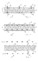
- Figure 1 shows a sandwich panel 1 comprising a core 2 and plate material 5 provided on either side of the core 2, whilst the sandwich panel 1 comprises at least one stiffening beam 3a, 3b, which extends into the core 2 of the sandwich panel 1.
- the plate material 5 is shown as plates 5a and 5b provided at the upper side and the lower side of the core 2.
- the first stiffening beams 3a extend near and abut against the plate 5a provided at the upper side of the core, and the second stiffening beams 3b extend near and abut against the lower plate 5b.
- first and the second stiffening beams 3a, 3b extend parallel to each other and opposite each other.
- the upper and lower stiffening beams 3b, 3a are disposed one above the other, as it were, in the plane indicated at I in figure 1 . It is also possible, however, to arrange the stiffening beams 3a, 3b in a different manner in the core, depending on the required properties. Thus it is also conceivable for the upper and lower beam 3a, 3b to be staggered relative to each other. It is also possible, for example, to provide more beams 3a than beams 3b, or conversely.
- the embodiment shown in figure 1 also comprises external stiffening beams 6. Said beams 6 also extend in the plane I and are disposed above the stiffening beams 3a, 3b provided in the core 2 of the sandwich panel, as it were.
- the sandwich panel shown in figure 1 has a width of 100 cm and a height of 16 cm, for example.
- the length of the panel, not shown in the figures, is 4 m.
- the core 2 is made of EPS and has a height of 15 cm.
- the plates 5a, 5b are each 5 mm thick and are made of wood.
- the stiffening beams 3a, 3b and 6 have a cross-sectional dimension of 2 by 3 cm and a length the same as the length of the panel 1.
- the stiffening beams 3a, 3b and 6 are also made of wood in this embodiment.
- Figure 2 shows another embodiment of a sandwich panel 1a, in which battens 7 are provided on the outer side, i.e. the side of the plate 5a remote from the core 2.
- the battens 7 are not disposed above the internal stiffening beams 3a, 3b.
- the panel 1a is moreover comprises a larger number of internal stiffening beams 3a, 3b in comparison with the panel 1 of figure 1 . Varying the number of internal stiffening beams 3 will result in varying degrees of stiffness of the panel 1.
- the core 2 is shown during the production of the sandwich panel 1 according to the invention.
- the core 2 is provided with grooves 4, which correspond as regards their dimensions to the stiffening beams 3a and 3b to be accommodated therein.
- Glue is applied to the grooves 4, whereupon the stiffening beams 3a, 3b are placed in the grooves 4 in the directions II and III, respectively.
- the plates 5a, 5b can be provided, and following that possibly the external beams 6 or 7.
- the core 2 has been described herein as being a mass, it may be advantageous to build up the core 2 of several.parts. It may also be advantageous to build up the core of several layers of insulation material, with the various layers extending parallel to, for example, the planes of the plates 5a, 5b of the plate material.
- the panel in addition to excellent insulating properties and an excellent stiffness, the panel also exhibits excellent failure behaviour. It has been found that when the panel according to the invention is subjected to extreme loads, the internal beams 3a and 3b will break one by one, and because of the fact that said beams are enclosed in the plate material 5, no parts flying about were observed upon breaking of the beams.
- the sandwich panel is not limited to the dimensions mentioned herein, which are merely given by way of illustration.
- the structure of the internal stiffening beams in any way be construed as limitative; it is for example possible to provide only the upper side of the core with stiffening beams, or to provide a larger or a smaller number of beams at the upper side than at the bottom side, depending on the desired properties of the panel.
Landscapes
- Engineering & Computer Science (AREA)
- Architecture (AREA)
- Civil Engineering (AREA)
- Structural Engineering (AREA)
- Building Environments (AREA)
- Laminated Bodies (AREA)
- Panels For Use In Building Construction (AREA)
Applications Claiming Priority (1)
| Application Number | Priority Date | Filing Date | Title |
|---|---|---|---|
| NL2001759A NL2001759C2 (nl) | 2008-07-04 | 2008-07-04 | Sandwichpaneel en werkwijze voor het vervaardigen van een sandwichpaneel. |
Publications (2)
| Publication Number | Publication Date |
|---|---|
| EP2141299A2 true EP2141299A2 (de) | 2010-01-06 |
| EP2141299A3 EP2141299A3 (de) | 2011-09-07 |
Family
ID=40342478
Family Applications (1)
| Application Number | Title | Priority Date | Filing Date |
|---|---|---|---|
| EP09164311A Withdrawn EP2141299A3 (de) | 2008-07-04 | 2009-07-01 | Sandwichplatte und Verfahren zur Herstellung einer Sandwichplatte |
Country Status (2)
| Country | Link |
|---|---|
| EP (1) | EP2141299A3 (de) |
| NL (1) | NL2001759C2 (de) |
Cited By (2)
| Publication number | Priority date | Publication date | Assignee | Title |
|---|---|---|---|---|
| EP3115524A1 (de) * | 2015-07-10 | 2017-01-11 | Lars Holm Pedersen | Isolierendes wandelement für tragende wände |
| WO2020167139A1 (en) * | 2019-02-13 | 2020-08-20 | Selvaag Gruppen As | Method of manufacturing an insulated external wall element, and the wall manufactured. |
Families Citing this family (1)
| Publication number | Priority date | Publication date | Assignee | Title |
|---|---|---|---|---|
| NL2022483B1 (nl) | 2019-01-31 | 2020-08-18 | Isobouw Systems Bv | Dakelement |
Citations (1)
| Publication number | Priority date | Publication date | Assignee | Title |
|---|---|---|---|---|
| EP0450731A1 (de) * | 1990-04-05 | 1991-10-09 | Opstalan B.V. | Panelartiges Isolierelement für Dächer oder Aussenwände |
Family Cites Families (5)
| Publication number | Priority date | Publication date | Assignee | Title |
|---|---|---|---|---|
| US3782049A (en) * | 1972-05-10 | 1974-01-01 | M Sachs | Wall forming blocks |
| US4163349A (en) * | 1977-05-26 | 1979-08-07 | Smith Glenn W | Insulated building panels |
| FI98398C (fi) * | 1994-06-10 | 1997-06-10 | Neste Oy | Seinäelementti |
| DE10134268A1 (de) * | 2001-07-18 | 2003-01-30 | Frankia Fahrzeugbau Pilote Gmb | Verfahren zur Herstellung eines Sandwichelementes und Sandwichelement |
| DE10250665B4 (de) * | 2002-09-10 | 2004-08-26 | Weinmann Holzbausystemtechnik Gmbh | Verfahren zur Herstellung von Sandwich-Wandelementen |
-
2008
- 2008-07-04 NL NL2001759A patent/NL2001759C2/nl active Search and Examination
-
2009
- 2009-07-01 EP EP09164311A patent/EP2141299A3/de not_active Withdrawn
Patent Citations (1)
| Publication number | Priority date | Publication date | Assignee | Title |
|---|---|---|---|---|
| EP0450731A1 (de) * | 1990-04-05 | 1991-10-09 | Opstalan B.V. | Panelartiges Isolierelement für Dächer oder Aussenwände |
Cited By (2)
| Publication number | Priority date | Publication date | Assignee | Title |
|---|---|---|---|---|
| EP3115524A1 (de) * | 2015-07-10 | 2017-01-11 | Lars Holm Pedersen | Isolierendes wandelement für tragende wände |
| WO2020167139A1 (en) * | 2019-02-13 | 2020-08-20 | Selvaag Gruppen As | Method of manufacturing an insulated external wall element, and the wall manufactured. |
Also Published As
| Publication number | Publication date |
|---|---|
| EP2141299A3 (de) | 2011-09-07 |
| NL2001759C2 (nl) | 2010-01-05 |
Similar Documents
| Publication | Publication Date | Title |
|---|---|---|
| US10024057B2 (en) | Construction panel system and methods of assembly thereof | |
| US9328506B2 (en) | Construction panel system and methods of assembly | |
| US7921609B2 (en) | Room arrangement, ship, building and method for constructing a room arrangement | |
| US8782991B2 (en) | Building roof structure having a round corner | |
| WO2009125289A2 (en) | Straight joint for sandwich panels and method of fabricating same | |
| US20100050549A1 (en) | Joint of parallel sandwich panels | |
| US20220090377A1 (en) | Wall assembly | |
| EP2141299A2 (de) | Sandwichplatte und Verfahren zur Herstellung einer Sandwichplatte | |
| EP2397620B1 (de) | Lamellierte Balkenkonstruktion | |
| US8863463B2 (en) | Insulation building system for a building structure | |
| WO2020117115A1 (en) | Building element, modular housing units, buildings and method | |
| KR101375028B1 (ko) | 구조용 목재가 포함된 단열복합패널 및 그 단열복합패널을 이용한 벽체 시공 방법 | |
| US20140272311A1 (en) | Composite sandwich panels and method of forming round corners in composite sandwich panels | |
| EP3042003B1 (de) | Bauelement mit ersten und zweiten deckschichten sowie zwischenkern aus zwei unterschiedlichen materialien | |
| KR20190001270U (ko) | 건축용 벽체 블록 및 건축용 벽체 모듈 조립체 | |
| WO2011073535A1 (en) | Building element and method for manufacturing building element | |
| WO2011154539A1 (en) | Building system | |
| EP2449185B1 (de) | Zusätzliches isoliersystem und ein verfahren zur isolierung einer fassade | |
| US20090260310A1 (en) | Method and system for providing an insulative wall structure | |
| US20140260085A1 (en) | Columnar structural component and method of forming | |
| WO2008139179A2 (en) | Composite floors | |
| US20180340340A1 (en) | Method and devices for producing a floating floor | |
| US20140260053A1 (en) | Columnar structural component and method of forming | |
| FI123601B (fi) | Seinärakenne ja menetelmä seinärakenteen valmistamiseksi | |
| EP2388385B1 (de) | Verfahren zur unterstützung eines unterstützenden elements auf einem bauelement, und ein bauelement |
Legal Events
| Date | Code | Title | Description |
|---|---|---|---|
| PUAI | Public reference made under article 153(3) epc to a published international application that has entered the european phase |
Free format text: ORIGINAL CODE: 0009012 |
|
| AK | Designated contracting states |
Kind code of ref document: A2 Designated state(s): AT BE BG CH CY CZ DE DK EE ES FI FR GB GR HR HU IE IS IT LI LT LU LV MC MK MT NL NO PL PT RO SE SI SK SM TR |
|
| PUAL | Search report despatched |
Free format text: ORIGINAL CODE: 0009013 |
|
| AK | Designated contracting states |
Kind code of ref document: A3 Designated state(s): AT BE BG CH CY CZ DE DK EE ES FI FR GB GR HR HU IE IS IT LI LT LU LV MC MK MT NL NO PL PT RO SE SI SK SM TR |
|
| RIC1 | Information provided on ipc code assigned before grant |
Ipc: E04C 2/292 20060101ALI20110803BHEP Ipc: E04C 2/38 20060101AFI20110803BHEP Ipc: E04C 2/296 20060101ALI20110803BHEP |
|
| 17P | Request for examination filed |
Effective date: 20120307 |
|
| 17Q | First examination report despatched |
Effective date: 20130711 |
|
| STAA | Information on the status of an ep patent application or granted ep patent |
Free format text: STATUS: THE APPLICATION IS DEEMED TO BE WITHDRAWN |
|
| 18D | Application deemed to be withdrawn |
Effective date: 20140702 |