EP2141272A1 - Knee lever for sewing machine - Google Patents
Knee lever for sewing machine Download PDFInfo
- Publication number
- EP2141272A1 EP2141272A1 EP09164286A EP09164286A EP2141272A1 EP 2141272 A1 EP2141272 A1 EP 2141272A1 EP 09164286 A EP09164286 A EP 09164286A EP 09164286 A EP09164286 A EP 09164286A EP 2141272 A1 EP2141272 A1 EP 2141272A1
- Authority
- EP
- European Patent Office
- Prior art keywords
- knee
- lever
- engagement
- rest
- knee rest
- Prior art date
- Legal status (The legal status is an assumption and is not a legal conclusion. Google has not performed a legal analysis and makes no representation as to the accuracy of the status listed.)
- Granted
Links
- 210000003127 knee Anatomy 0.000 title claims abstract description 230
- 238000009958 sewing Methods 0.000 title claims abstract description 45
- 230000007246 mechanism Effects 0.000 claims abstract description 57
- 230000014759 maintenance of location Effects 0.000 claims description 4
- 230000006835 compression Effects 0.000 description 11
- 238000007906 compression Methods 0.000 description 11
- 239000004744 fabric Substances 0.000 description 7
- 230000000994 depressogenic effect Effects 0.000 description 5
- 238000003780 insertion Methods 0.000 description 5
- 230000037431 insertion Effects 0.000 description 5
- 238000001514 detection method Methods 0.000 description 2
- 238000010586 diagram Methods 0.000 description 2
- 239000000463 material Substances 0.000 description 2
- 239000002184 metal Substances 0.000 description 2
- 230000004048 modification Effects 0.000 description 2
- 238000012986 modification Methods 0.000 description 2
- 230000002787 reinforcement Effects 0.000 description 2
- 229920003002 synthetic resin Polymers 0.000 description 2
- 239000000057 synthetic resin Substances 0.000 description 2
- 239000000872 buffer Substances 0.000 description 1
- 230000008878 coupling Effects 0.000 description 1
- 238000010168 coupling process Methods 0.000 description 1
- 238000005859 coupling reaction Methods 0.000 description 1
- 238000006073 displacement reaction Methods 0.000 description 1
- 230000003028 elevating effect Effects 0.000 description 1
- 210000003414 extremity Anatomy 0.000 description 1
- 230000002349 favourable effect Effects 0.000 description 1
- 238000009434 installation Methods 0.000 description 1
- 239000004973 liquid crystal related substance Substances 0.000 description 1
- 230000000149 penetrating effect Effects 0.000 description 1
- 230000002093 peripheral effect Effects 0.000 description 1
- 230000004044 response Effects 0.000 description 1
Images





Classifications
-
- D—TEXTILES; PAPER
- D05—SEWING; EMBROIDERING; TUFTING
- D05B—SEWING
- D05B29/00—Pressers; Presser feet
- D05B29/02—Presser-control devices
-
- D—TEXTILES; PAPER
- D05—SEWING; EMBROIDERING; TUFTING
- D05D—INDEXING SCHEME ASSOCIATED WITH SUBCLASSES D05B AND D05C, RELATING TO SEWING, EMBROIDERING AND TUFTING
- D05D2205/00—Interface between the operator and the machine
- D05D2205/02—Operator to the machine
Definitions
- the present disclosure relates to a knee lever that elevates a presser foot of a sewing machine through operation controlled user's knees.
- Sewing machines have been conventionally provided with a presser foot for pressing a workpiece cloth against a sewing machine bed.
- the presser foot is typically attached to a lower end of a presser bar which is vertically movably supported by a head provided at the extremity of a sewing machine arm.
- a presser foot lifting unit provided with a presser foot lifting lever for lifting the presser foot is generally provided within the head.
- the presser foot lifting unit is configured to vertically move the presser bar and the presser foot by manual rotation of the presser foot lifting lever by the user.
- Some sewing machines are provided with a knee lever instead of a manually operated presser foot lifting lever to allow the user to vertically move the presser foot by operation of the knee lever with his/her knees.
- Such types of sewing machines are provided, at the sewing machine bed (or sewing machine table), components such as a knee lever attachment (hereinafter referred to as an attachment), an operative shaft rotating integrally with the attachment and a link mechanism providing linkage between the operative shaft and the presser foot. Under such configuration, when the knee lever is laterally moved by user operation, the attachment and the operative shaft are rotated to vertically move the presser foot through the link mechanism.
- JP S62-15029 Y hereinafter referred to as patent publication 1 in which a guide mechanism is provided between the attachment and the operative shaft.
- the guide mechanism is provided with a guide member including a guide cam and being secured on the sewing machine table and a swing arm provided on the operative shaft.
- the guide mechanism is configured to guide the attachment and consequently the knee lever through engagement of a pair of pins disposed at a lower portion of the attachment with the guide cam and the swing arm.
- the knee lever on the other hand, is provided with a rod secured on the attachment and a knee rest provided on the rod.
- the rod comprises a vertical section and a horizontal section and is generally curved in an "L-shape".
- the horizontal section is secured to the attachment by a screw serving as a fastening element.
- the guide mechanism guides the knee rest so that the path of its movement follows the user knee movement. Such guidance feature allows smooth and stress free knee operation of the knee lever.
- Patent publication 2 discloses a presser lifting unit allowing detachable attachment of knee lever to provide the user with an option to control the vertical movement of the presser foot with the knee lever.
- the problem encountered in the knee lever operation disclosed in patent publication 1 was the variability in the requirement in the positioning of the knee rest depending upon the physiques of the user. For instance, some users may feel that the knee rest is too far away whereas some may feel that it is too close for stress free operation. In such case, the user is forced to go through a troublesome task of knee lever adjustment involving unfastening of the screw with special tools such as a wrench, then, laterally moving the horizontal section of the rod to reposition the knee lever in its entirety, and fastening the screw again with the tool.
- the guide mechanism mentioned earlier for providing guidance during the knee lever operation is disposed on the sewing machine by screw fastening as was the case for the attachment. Such configuration also complicated the structure of the sewing machine.
- the knee lever disclosed in patent publication 2 does not allow adjustment in its positioning relative to the sewing machine, and thus, provided poor operability if its positioning did not suit the physiques of the user.
- One object of the present disclosure is to provide a knee lever for use with a sewing machine that can be adjusted in positioning to meet the requirements of user preference without requiring any additional features on the sewing machine.
- a knee lever for use in a sewing machine including a bed having an attachment, a head, and a presser bar being supported by the head and having a presser foot at a lower end thereof.
- the knee lever is detachably attached to the attachment to be operated by knee contact for lifting the presser foot.
- the knee lever includes a lever that is detachably attached to the attachment; a knee rest that is mounted on the lever and that is operated by knee contact, with the lever being attached to the attachment; and an adjustment mechanism that allows adjustment in position of knee contact of the knee rest.
- the adjustment mechanism provides improved operability by allowing the user to adjust the position of the knee lever to suit the user's physique or preferences. Further, the adjustment mechanism has been provided at the knee lever and thus, the sewing machine may maintain its conventional configuration without having to be provided with the adjustment mechanism.
- FIGS. 1 to 12 One exemplary embodiment applying the present disclosure to a household sewing machine will be described hereinafter with reference to FIGS. 1 to 12 .
- the following description will be given with an assumption that the direction in which the operator (user) positions himself/herself relative to the sewing machine is the front side.
- a sewing machine M is provided with a bed 1, an upwardly extending pillar 2 standing on the right end of bed 1, and an arm 3 extending leftward over bed 1 from the upper end of pillar 2.
- the extreme left end of arm 3 constitutes an integral head 4.
- Arm 3 contains a laterally oriented main shaft not shown and a sewing machine motor 5 shown in FIG. 12 that rotates the sewing machine main shaft.
- a hand pulley 3a is provided to allow manual rotation of the main shaft.
- Head 4 has a needle bar having a sewing needle (neither of which are shown) attached on its lower end and a presser bar 7 having a presser foot 6 attached to its lower end.
- Presser bar 7 situated behind the needle bar is supported vertically movably by a sewing machine frame F and is vertically driven by a presser bar drive mechanism 8.
- arm 3 further contains components such as a needle bar drive mechanism that vertically drives the needle bar based on the rotation of the sewing machine main shaft, a needle bar swing mechanism that laterally (left and right) swings the needle bar in a direction orthogonal to the cloth feed direction, and a thread take-up drive mechanism that vertically moves a thread take-up in synchronism with the vertical movement of the needle bar.
- a needle plate 1a Provided on the upper surface of bed 1 is a needle plate 1a.
- components such as a cloth feed mechanism that vertically and longitudinally moves a feed dog, horizontal shuttle mechanism containing a bobbin thread bobbin that forms stitches on a workpiece cloth W in cooperation with sewing needle, and a thread cut mechanism that cuts a needle thread and a bobbin thread are provided.
- presser bar drive mechanism 8 for vertically moving presser bar 7 having a presser foot 6 attached to it.
- a rack forming element 11 is fitted vertically movably over it and a stop ring 47 is secured at the upper end of presser bar 7.
- Presser bar 7 is further provided with a presser bar clamp 13 secured at its vertical mid portion and a spring 14 is fitted over it at a portion between rack forming element 11 and presser bar clamp 13.
- sewing machine frame F is provided with presser foot drive motor 15 having a drive gear 15a attached on its output shaft and an intermediate gear 16 in mesh with drive gear 15a.
- the intermediate gear 16 is provided integrally with a small-diameter pinion 16a in mesh with a rack not shown formed on rack forming element 11.
- rack forming element 11 when rack forming element 11 is elevated, the upper end of rack forming element 11 is placed in abutment with stop ring 12 to elevate presser bar 7 such that presser foot 6 is raised to an elevated position spaced by a predetermined spacing from the workpiece cloth as can be seen in FIG.2 .
- Sewing machine M according to the present exemplary embodiment is provided with a presser foot lifting lever 17 for manually operating presser foot 6 independent of presser bar drive mechanism 8.
- a presser foot lifting lever 17 is pivoted on sewing machine frame F by a pin 17a. Presser foot lifting lever 17, when manually operated at its free end, vertically moves presser foot 6 through presser bar clamp 13.
- An attachment 19 is provided on bed 1 to allow detachable attachment of knee lever 20 for elevating presser foot 6 through operation by user's knees.
- the structures in the proximity of knee lever 20 and attachment 19 will be described with reference to FIGS. 3 to 10B .
- Attachment 19 employed in the present exemplary embodiment is similar to those provided in conventional sewing machines.
- Attachment 19 is positioned slightly to the right from the lower mid portion of bed 1 and is provided with a laterally elongate stationary frame 21 shown in FIGS.3 to 4B and a rotary element 22 provided rotatably on stationary frame 21.
- rotary element 22 is integrally provided with a shaft 23 that penetrates front and rear walls 21a and 21b of stationary frame 21, and an arm 24 projecting rightward relative to shaft 23.
- a cylindrical engagement retainer 23a is provided that allows detachable attachment of knee lever 20.
- Engagement retainer 23a has a notch 23b running in the axial direction at its front portion and an elastic tab 23c opposing notch 23b.
- engagement subject 32 is radially urged by elastic tab 23c, to secure the fitting engagement and allow rotary element 22 to rotate integrally with knee lever 20.
- Rotary element 22 is appropriately limited in amount of rotation by a regulator not shown so as to rotate between horizontal position show in FIG. 4A in which arm 24 is substantially horizontal and an inclined position shown in FIG.4B in which arm 24 is inclined by a predetermined angle.
- the rotation of knee lever 20, being limited by the regulator through rotary element 22, ranges between a standby position shown in FIG.1 in which knee lever 20 in its entirety is oriented substantially vertically in front view, and an operative position shown in FIG.2 in which knee lever 20 in its entirety us inclined by a predetermined angle.
- a torsion coil spring 25a is wound, whereas a helical extension spring 25b is disposed between the base end of arm 24 and left wall 21c of rotary element 22.
- Torsion coil spring 25a and helical extension spring 25b bias rotary element 22 toward the horizontal position, in other words, clockwise as viewed in FIG.4B .
- a displacement sensor such as a potentiometer 26 is provided for sensing the position of knee lever 20.
- a rotary shaft of potentiometer 26 an arm 26a and a helical coil spring 27 are provided that biases arm 26a toward the upper surface of arm 24a. Potentiometer 26, thus, switches its resistance by rotation of arm 26a through rotary element 22 in response to the rotation of knee lever 20.
- knee lever 20 is provided with a reverse J-shaped lever 30, and a knee rest 31 which receives the user's knee when knee lever 20 is operated.
- Lever 30 comprises a metal rod, for example, and is bent to obtain the above described shape.
- One end, in this case, the upper end shown in FIG. 6 is integrally provided with a radially expanding engagement subject 32.
- Engagement subject 32 is configured to be held by the elasticity of elastic tab 23c when fitted into engagement retainer 23a of attachment 19.
- the lower portion of lever 30 is oriented obliquely downward as can be seen in FIG.1 .
- the lower portion of lever 30 serves as a support section 30a which supports knee rest 31 at an eccentric location of knee rest 31, in other words, at a location displaced from the center of knee rest 31.
- Support section 30a has three holes 33a, 33b, and 33c defined on it for example, as shown in FIG.6 .
- Engagement pin 34 is secured within hole 33a such that one end of engagement pin 34 is disposed so as to be coplanar with the outer peripheral surface of lever 30, whereas the other end projects radially outward relative to lever 30.
- Engagement pin 34 and support section 30a corresponds to a later described engagement portion 52.
- the above mentioned engagement pin 34 is a grooved pin having a groove 34a running axially on the side surface for retaining purpose.
- auxiliary pin 35 is secured within hole 33b such that both ends of auxiliary pin 35 projects radially outward relative to lever 30.
- the above mentioned auxiliary pin 35 is a spring pin having a groove 35a running axially on the side surface for retaining purpose.
- hole 33c of support section 30a is a utility hole for inserting an assembly pin of knee rest 31.
- a compression coil spring 36 is wound on the lower portion of support section 30a and a washer 37 is disposed between auxiliary pin 35 and compression coil spring 36. As later described, compression coil spring 36 biases knee rest 31 downward, as viewed in FIGSS.5A and 5B, relative to lever 30.
- knee rest 31 is split into a first knee rest case 40 and a second knee rest case 41 and when assembled, exhibit a pillar-like shape such as a square prism, with its corners chamfered to possess chamfered surfaces 42.
- the first and second knee rest cases 40 and 41 are both made of synthetic resin material, for instance, and are each integrally molded to have reinforcement ribs 43 in grid arrangement in their interiors.
- First knee rest case 40 shown on the upper side of FIG.8 has a pair of screw holes 40a and 40b defined on it, whereas on a portion of second knee rest case 41 shown on the lower side that corresponds to screw holes 40a and 40b, bosses 41a and 41b are integrally defined to receive screws 44 screwed into screw holes 40a and 40b for assembly of the first and the second knee rest cases 40 and 41.
- a support subject 46 is defined which is supported by support section 30a of lever 30. A description will be given on support subject 46 with reference to FIGS.9 to 10B .
- a plurality of U-shaped notches 47 is defined as can be seen in FIG. 8 . Notches 47 are designed to leave slight spacing from the outer periphery of support section 30a.
- an upper support subject 48 is integrally formed on the upper end of second knee rest 41. As can be seen in FIG.10A , upper support subject 48 is provided with an insertion hole 49 penetrating through the upper wall of second knee rest case 41 and being placed in sliding contact with the outer periphery of support section 30a and a plurality of (3, for example) engagement grooves 50a, 50b, and 50c running radially outward from insertion hole 49.
- Engagement grooves 50a to 50c collectively define a T-shape and are each recessed upward to allow insertion of engagement pin 34 from below. That is, engagement grooves 50a and 50b and engagement grooves 50b and 50c define an angular interval of 90 degrees respectively between them. The angular intervals between engagement grooves 50a, 50b, and 50c and the number of engagement grooves provided may be varied as found appropriate.
- Second knee rest case 41 is further provided integrally with a cylindrical lower support subject 51 which is slightly elevated from the bottom of second knee rest case 41.
- the inner periphery of lower support subject 51 is placed in sliding contact with the outer periphery of support section 30a and is biased downward at its upper end by compression coil spring 36.
- the bias of compression coil spring 36 forces engagement pin 34 to be in constant engagement with either of engagement grooves 50a to 50c so that knee rest 31 is locked in a stationary state shown in FIG.5A in which relative rotation about lever 30 is prohibited.
- engagement pin 34 is disengaged from engagement grooves 50a to 50c to allow relative rotation of knee rest 31 to lever 30 as shown in the state described in FIG.5B .
- Notches 47, upper support section 48 and lower support section 51 constitute support subject 46 which is supported vertically movably and rotatably by support section 30a of lever 30.
- knee rest 31 is allowed to revolve 360 degrees about lever 30 in both in arrow D1 direction (clockwise) and arrow D2 direction (counterclockwise) shown in FIG.11A .
- the mounting position of knee rest 31 is switched. More specifically, the mounting position is switched between a first position shown in FIG.11A in which engagement pin 34 is engaged with engagement groove 50a, a second position shown in FIG.11B in which engagement pin 34 is engaged with engagement groove 50b, and a third position shown in FIG.11C in which engagement pin 34 is engaged with engagement groove 50c.
- Support subject 46 and engagement grooves 50a to 50c constitute engagement subject 53 that is disengagably engaged with engagement portion 52 to switch the mounting position of knee rest 31 relative to lever 30.
- Engagement subject 53 and engagement portion 52 constitute an adjustment mechanism 54 of the present disclosure.
- Controller 55 responsible for controlling sewing machine M is configured primarily by a microcomputer including components such as a CPU 55a, a ROM 55b, and a RAM 55c.
- Controller 55 establishes connections with components such as start/stop switch 9, presser foot vertically moving switch 10, and potentiometer 26, as well as a drive circuit 56 for sewing machine motor 5, and a drive circuit 57 for presser foot drive motor 15.
- Controller 55 performs operations such as calculation for obtaining the position of knee lever 20 (in the present disclosure, determining whether or not knee lever 20 is in the operative position) based on the resistance sensed by potentiometer 26.
- ROM 55b stores a sew control program etc., while memory such as buffers and counters required for execution of various controls are allocated to RAM 55c as required.
- Controller 55 executes sewing operations on a workpiece cloth by driving actuators such as sewing machine motor 5 and presser foot drive motor 15 according to the sew control program.
- knee lever 20 when knee lever 20, being attached to attachment 19 of rotary element, is in a standby position, presser foot 6 is biased downward by spring 14 along with presser bar 7 through presser bar clamp 13.
- knee rest 31 is switched to the first position indicated by a solid line in FIG.1 where it is adjusted to contact the right knee of the user schematically illustrated as a right knee RH at contact position P1.
- the left knee of the user is similarly schematically illustrated as a left knee LH.
- controller 55 determines whether or not knee lever 20 is in the operative position based on the detection signal produced by potentiometer 26.
- presser foot drive motor 15 is driven to move presser foot 6 to the elevated position through drive gear 15a, intermediate gear 16 and rack forming element 11.
- controller 55 drives presser foot drive motor 15 based on detection signal produced by potentiometer 26 to lower presser foot 6 to the pressed position.
- knee rest 31 may be moved closer to right knee RH by adjustment mechanism 54 to consequently move the contact position closer toward the user. More specifically, when the user lifts knee rest 31 in the direction indicated by the arrow shown in FIG.5B against the bias of compression coil spring 36, engagement pin 34 is disengaged from engagement groove 50a. Under such state, when knee rest 31 is rotated about lever 30 in arrow D1 direction or arrow D2 direction to locate engagement pin 34 with engagement groove 50b, the mounting position of knee lever 31 is switched from the first position to the second position. Thus, knee rest is adjusted to contact right knee RH of the user at contact position P2 as shown in FIG.1 .
- knee rest 31 is switched to the third position by going through the same operation. More specifically, knee rest 31 is lifted relative to lever 30 by the user to disengage engagement pint 34 from engagement groove 50b and thereafter rotated about lever 30 to locate engagement pin 34 with engagement groove 50c. Thus, knee rest 31 is adjusted to contact right knee RH of the user at contact position P3.
- the above described adj ustment may be made with knee lever 20 attached to attachment 19 but can be done much easier by removing knee lever 20 from attachment 19.
- presser foot 6 may be vertically moved through operation of a presser foot lifting lever 17 or presser foot lifting vertically moving switch 10 without using knee lever 20.
- knee lever 20 is configured to allow adjustment in contact position of knee rest 31 relative to right knee RH from the selection of contact positions P1 to P3.
- knee lever 20 need not be repositioned in its entirety through troublesome fastening/unfastening of coupling elements such as screws when the user feels that knee lever 20 is too far or too close.
- This allows the user to readily adjust knee lever 20 to the desired operational position suitable for the users' physique and preference without any troublesome use of tools, thereby improving operability of knee lever 20.
- adjustment mechanism 54 is provided at knee lever 20 and not at the sewing machine, the sewing machine does not require any adjustment features in addition to its conventional configuration.
- knee lever 20 may be used in different types of sewing machines that is designed for detachable attachment of a knee lever and allow adjustments in the contact position of knee lever from the selection of contact positions P1 to P3.
- Adjustment mechanism 54 comprises engagement portion 52 provided at lever 30 and engagement subject portion 53 provided at knee rest 31 which disengagably engages with engagement portion 52 to allow switching in the mounting position of knee rest 31 relative to lever 30. This allows the mounting position of knee rest 31 to be switched by merely engaging/disengaging engagement subject 53 to/from engagement portion 52 to simplify the configuration of adjustment mechanism 54.
- Engagement portion 52 comprises support section 30a and engagement pin 34.
- Engagement subject 53 comprises a plurality of engagement grooves 50a to 50c being disposed around support section and selectively engaging with engagement pin 34, and support subject 46 being supported by support section 30a so as to be switchable between the engagement positions determined by the selective engagement of engagement pin 34 with engagement grooves 50a to 50c.
- the above arrangement minimizes the number of parts required at adjustment mechanism 54 to simplify its configuration as much as possible while allowing a compact installation of adjustment mechanism 54 within knee rest 31. Further, usability is improved by allowing the mounting position of knee rest 31 to be switched to the desired position (the first to third position) by mere switching of the engagement positions as described earlier.
- FIGS.13A to 16 describe a second exemplary embodiment of the present disclosure. Elements that are identical to the first exemplary embodiment are represented by identical reference symbols and a description will be given only on elements that differ from the first exemplary embodiment.
- Knee lever 60 of the second exemplary embodiment differs from knee lever 20 of the first exemplary embodiment in the following respects.
- Knee rest 61 of knee lever 60 is made of synthetic resin material, for example, and is provided integrally with a rectangular knee rest body 61a extending in the front-rear direction, and an upper mount 61b and lower mount 61c provided at the upper portion and lower portion of knee rest body 61a respectively.
- the surface facing right knee RH, the left side as viewed in FIG.13A defines an operative surface 61d.
- An adjustment mechanism 62 of the present exemplary embodiment is provided with a link mechanism 63 that joins the knee rest 61 and lever 30, and a retention mechanism that retains the distance between knee rest 61 and lever 30 at a predetermined distance.
- Link mechanism 63 is provided with a pair of parallel links namely a first link 65 and a second link 66 that interpose knee rest 61 and lever 30.
- upper mount 61b and lower mount 61c of knee rest 61 is provided with hinge pins 67a and 67b, for example, whereas on the lower portion of lever 30, hinge pins 68a and 68b, for example, are provided at locations corresponding to hinge pins 67a and 67b of knee rest 61.
- Both first and second links 65 and 66 have a reversed C-shaped cross section that extend in a linear fashion and have identical lengths.
- first link 65 is rotatably linked on lever 30 by hinge pin 68a and the other end (left end) is linked rotatably to knee rest 61 by hinge pin 67a.
- the right end of second link pin 66 is linked rotatably to lever 30 by hinge pin 68b and the left and is linked rotatably to knee rest 61 by hinge pin 67b.
- First link 65, second link 66, hinge pins 67a, 67b, 68a, and 68b constitute link mechanism 63 that links knee rest 61 and lever 30 with adjustment capabilities in the distance between the linked knee lever 61 and lever 30.
- Link mechanism 63 is configured as a parallel four segment link mechanism that moves knee rest 61 toward lever 30 substantially parallel.
- Retention mechanism 64 is disposed at link mechanism 63 and is provided with a positioning plate 71, a repositioning button 72 configured to longitudinally reciprocate between a protruding position and a depressed position relative to positioning plate 71, and a compression coil spring 73 that biases positioning button toward the protruding position.
- positioning plate 71 is made of metal, for example, and is integrally provided with a head 71a having a guide groove 74 defined on it and a fastening portion 71b extending longitudinally to exhibit ,in its entirety, a shape resembling a bottle cap opener.
- a through hole 71c is provided through which hinge pin 67a of knee rest 61 penetrates, and a couple of upper mount hole 71d and a lower mount hole 71e are provided on the lower portion of fastening portion 71b.
- Guide groove 74 of head 71a runs along the circumference centering on through hole 71c and guides a later described small diameter portion 72a of repositioning button 72 shown in FIG.15B .
- Head 71a has fitting holes 74, 74b, and 74c defined on it along guide groove 74 in the listed sequence from the top of guide groove 74. Fitting holes 74a, 74b, and 74c allow the fitting engagement of a later described large diameter portion 72b of repositioning button 72 as shown in FIG.15A .
- Knee rest 61 has a couple of bosses 61f and 61g disposed immediately under upper mount 61b as shown in FIG.13B .
- Positioning plate 71 is fastened on knee rest 61 through screw engagement of screws 75 inserted though mount holes 71d and 71e with bosses 61f and 61g of knee rest 61.
- Repositioning button 72 is inserted through the insertion holes 65c.
- Repositioning button 72 comprises a large diameter portion 72b being cylindrical in form, a small diameter portion 72a provided at the front end (relatively closer to positioning plate 71) of large diameter portion 72b, and a stop ring 72c attached on a relatively forward portion of large diameter portion 72b.
- Compression coil spring 73 is situated between stop ring 72c and rear wall 65b of first link 65 to forwardly bias repositioning button 72.
- Repositioning button 72 is thus, moved forward to the protruding position (refer to 15A) in which stop ring 72c is locked in against front wall 65a of first link 65 and large diameter portion 72 of repositioning button 72 is fitted into one of fitting holes 74a to 74c from the rear side. This fitting engagement unmovably locks positioning plate 71 against first link 65 to prohibit movement of link mechanism 63.
- repositioning button 72 is moved to the depressed position shown in FIG.15B being coplanar with positioning plate 71. Under this state, relative movement of repositioning button 72 along guide groove 74 is permitted, and thus, knee rest 61 can be moved closer to the user to be moved away from lever 30 as required. Then by locating repositioning button 72 with either of fitting holes 74a to 74c and canceling the depression of repositioning button 72, the position of the knee rest is switched.
- the position of knee rest 61 is switched between the first position shown in solid line in FIG.13A in which large diameter portion 72a is fitted into fitting hole 74a, the second position shown in double-dot chain line in FIG.13A in which large diameter portion 72a is fitted into fitting hole 74b, and the third position shown in double-dot chain line in FIG.13A in which large diameter portion 72c is fitted into fitting hole 74c.
- knee lever 60 When knee lever 60 is in a standby position, with lever 30 being attached to attachment 19 of rotary element, presser foot 6 is lowered to the press position. At this instance, knee rest 61 is switched to the first position indicated by a solid line in FIG.13A where it is adjusted to contact right knee RH at contact position P11. If relocation button 72 is not depressed, the fitting engagement of large diameter portion 72b of repositioning button 72 with fitting engagement hole 74a retains the positioning of knee rest 61 and lever 30 with relatively small distance therebetween.
- knee rest 61 and consequently the contact position may be moved closer to right knee RH through following adjustments.
- Repositioning button 72 is depressed to the depressed position against the bias of compression coil spring 73 and knee rest 61 is moved away from lever 30 with the depressed state of repositioning button 72 maintained.
- small diameter portion 72a of repositioning button 72 is relatively moved along guide groove 74 toward fitting hole 74b from fitting hole 74a.
- the position of the knee rest 61 is switched from the first position to the second position.
- knee rest 61 is adjusted to contact right knee RH of the user at contact position P12 as shown in FIG.13A .
- the user may further depress repositioning button 72 again to further increase the distance between knee rest 61 and lever 30.
- the position of the knee rest 61 is switched from the second position to the third position.
- knee rest 61 is adjusted to contact right knee RH of the user at contact position P13 as shown in FIG.13A .
- knee rest 61 is moved substantially parallel to lever 30 by link mechanism 63 to place operative surface 61d contacting right knee RH in a substantially vertical state at contact positions P11 to P13.
- adjustment mechanism 62 is provided with a link mechanism 63 that links lever 30 and knee rest 61 and that allows adjustment (modification) in the distance between lever 30 and knee rest 61.
- link mechanism 63 employs a parallel four segment configuration to allow operative surface 61d of knee lever 61 to exhibit a substantially vertical state at each of contact positions P11 to P13. Such arrangement allows the user to operate the operative surface 61d stresslessly to provide favorable operability.
- Adjustment mechanism 62 is further provided with retention mechanism 64 that retains a predetermined distance between lever 30 and knee rest 61. Thus, the mounting position of knee rest 61 once specified can be prevented from being precariously switched to other mounting positions.
- FIGS.17A and 17B show a third exemplary embodiment of the present disclosure. Elements that are identical to the second exemplary embodiment are identified with identical reference symbols and a description will be given only on elements that differ.
- Knee lever 80 of the third exemplary embodiment differs from knee lever 60 of the second exemplary embodiment in the following respects.
- Knee lever 80 is provided with a link mechanism 81 having a first link 83 which is reduced in length compared to first link 65 of the second exemplary embodiment.
- Link mechanism 81 is a non-parallel four segment link mechanism in which the length of first link 83 and second link 66 differ to allow the position of knee rest 61 to be switched such that operative surface 61d of knee lever 80 in operative position presents a nearly vertical inclination.
- knee rest 61 is switched, in listed sequence from right side as viewed in FIG. 17A , between: the first position shown in FIG.17A in which large diameter portion 72a of repositioning button 72 is fitted into fitting hole 74a, the second position in which large diameter portion 72b is fitted into fitting hole 74b, and the third position shown in FIG.13A in which large diameter portion 72c is fitted into fitting hole 74c.
- knee rest 61 in the operative position, gradually switches its inclination to proximate the vertical orientation as it proceeds to the second and the third position.
- link mechanism 81 of the third exemplary embodiment is configured to place operative surface 61d in a substantially vertical incline at the operative position of knee lever 60 by switching the position of knee rest 61 to the third position.
- knee rest 61 can be approximated to lever 30 in alignment with lever 30, and place operative surface 61d to present a substantially vertical incline.
- the above described configuration allows operative surface 61d of knee rest 61 to be adjusted in the desired angle according to user preference to improve the usability of knee lever 60.
- the present disclosure is not limited to the exemplary embodiments described above or shown in the accompanying drawings but may be modified or expanded as follows.
- the present disclosure may be applied to sewing machines in general that are provided with presser bar 7 having presser foot 6 at its lower end and not limited to a general household sewing machine M.
- the shape of knee rest 31 is not limited to a square prism but may come in any form as long as it is a three dimensional element provided with an operative surface that is operated through contact to the user' s knees and that is supported by support section 30a at a position displaced from the center of the three dimensional element such as a cylindrical column, a triangular prism, and a pentagonal prism. Under such modified configuration also, adjustment can be made on the contact position of the operative surface relative to the user's knee by rotating the three dimensional element about support section 30a.
- repositioning button 72 serves as the engagement portion and fitting holes 74a to 74c serve as the engagement subject portion.
- Engagement portion and engagement subject may come in any form as long as they are provided between the lever and the knee rest and allow switching in the mounting position of the knee rest relative the lever through disengagable engagement of the engagement subject to the engagement portion.
- the parallel and non-parallel four segment link mechanism provided in the second and third exemplary embodiments may be replaced by other link mechanism with different number of segments.
Landscapes
- Engineering & Computer Science (AREA)
- Textile Engineering (AREA)
- Sewing Machines And Sewing (AREA)
Abstract
Description
- The present disclosure relates to a knee lever that elevates a presser foot of a sewing machine through operation controlled user's knees.
- Sewing machines have been conventionally provided with a presser foot for pressing a workpiece cloth against a sewing machine bed. The presser foot is typically attached to a lower end of a presser bar which is vertically movably supported by a head provided at the extremity of a sewing machine arm. Under such configuration, a presser foot lifting unit provided with a presser foot lifting lever for lifting the presser foot is generally provided within the head. The presser foot lifting unit is configured to vertically move the presser bar and the presser foot by manual rotation of the presser foot lifting lever by the user.
- Some sewing machines are provided with a knee lever instead of a manually operated presser foot lifting lever to allow the user to vertically move the presser foot by operation of the knee lever with his/her knees. Such types of sewing machines are provided, at the sewing machine bed (or sewing machine table), components such as a knee lever attachment (hereinafter referred to as an attachment), an operative shaft rotating integrally with the attachment and a link mechanism providing linkage between the operative shaft and the presser foot. Under such configuration, when the knee lever is laterally moved by user operation, the attachment and the operative shaft are rotated to vertically move the presser foot through the link mechanism.
- One example of such sewing machine is disclosed, for example, in
JP S62-15029 Y patent publication 1 in which a guide mechanism is provided between the attachment and the operative shaft. The guide mechanism is provided with a guide member including a guide cam and being secured on the sewing machine table and a swing arm provided on the operative shaft. The guide mechanism is configured to guide the attachment and consequently the knee lever through engagement of a pair of pins disposed at a lower portion of the attachment with the guide cam and the swing arm. The knee lever, on the other hand, is provided with a rod secured on the attachment and a knee rest provided on the rod. The rod comprises a vertical section and a horizontal section and is generally curved in an "L-shape". The horizontal section is secured to the attachment by a screw serving as a fastening element. In the disclosed sewing machine, when the user laterally moves his/her knees to laterally operate the knee rest, the guide mechanism guides the knee rest so that the path of its movement follows the user knee movement. Such guidance feature allows smooth and stress free knee operation of the knee lever. - Another example is disclosed in
JP H11-207066 A patent publication 2.Patent publication 2 discloses a presser lifting unit allowing detachable attachment of knee lever to provide the user with an option to control the vertical movement of the presser foot with the knee lever. - The problem encountered in the knee lever operation disclosed in
patent publication 1 was the variability in the requirement in the positioning of the knee rest depending upon the physiques of the user. For instance, some users may feel that the knee rest is too far away whereas some may feel that it is too close for stress free operation. In such case, the user is forced to go through a troublesome task of knee lever adjustment involving unfastening of the screw with special tools such as a wrench, then, laterally moving the horizontal section of the rod to reposition the knee lever in its entirety, and fastening the screw again with the tool. The guide mechanism mentioned earlier for providing guidance during the knee lever operation is disposed on the sewing machine by screw fastening as was the case for the attachment. Such configuration also complicated the structure of the sewing machine. - The knee lever disclosed in
patent publication 2 does not allow adjustment in its positioning relative to the sewing machine, and thus, provided poor operability if its positioning did not suit the physiques of the user. - One object of the present disclosure is to provide a knee lever for use with a sewing machine that can be adjusted in positioning to meet the requirements of user preference without requiring any additional features on the sewing machine.
- In one aspect of the present disclosure, a knee lever is provided for use in a sewing machine including a bed having an attachment, a head, and a presser bar being supported by the head and having a presser foot at a lower end thereof. The knee lever is detachably attached to the attachment to be operated by knee contact for lifting the presser foot. The knee lever includes a lever that is detachably attached to the attachment; a knee rest that is mounted on the lever and that is operated by knee contact, with the lever being attached to the attachment; and an adjustment mechanism that allows adjustment in position of knee contact of the knee rest.
- According to the above described configuration, the adjustment mechanism provides improved operability by allowing the user to adjust the position of the knee lever to suit the user's physique or preferences. Further, the adjustment mechanism has been provided at the knee lever and thus, the sewing machine may maintain its conventional configuration without having to be provided with the adjustment mechanism.
- Other objects, features and advantages of the present disclosure will become clear upon reviewing the following description of the illustrative aspects with reference to the accompanying drawings, in which,
-
FIG.1 is a front view of a sewing machine and a knee lever in a standby position according to one exemplary embodiment of the present disclosure; -
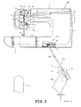
FIG.2 corresponds toFIG.1 with the knee lever being moved to the operative position; -
FIG.3 is an enlarged plan view of an attachment; -
FIG.4A is an enlarged front view of the attachment with the knee lever in the standby position; -
FIG.4B corresponds toFIG.4A and is a front view the knee lever in the operative position; -
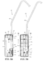
FIG.5A is a side view of a knee rest being locked unmovably relative to a lever; -
FIG.5B is a side view of a knee rest being allowed to rotate relative to the lever; -
FIG.6 is a side view of the lever in its entirety; -
FIG. 7A is a cross sectional view taken along line VIIa-VIIa ofFIG.6 ; -
FIG.7B is a cross sectional view taken along line VIIb-VIIb ofFIG.6 ; -
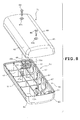
FIG.8 is an exploded perspective view of the knee rest; -
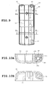
FIG.9 is a depicts an interior structure of a second knee rest case; -
FIG.10A is an enlarged cross sectional view taken along line Xa-Xa ofFIG.9 ; -
FIG.10B is an enlarged cross sectional view taken along line Xb-Xb ofFIG.9 ; -
FIG.11A, 11B, 11C and 11D are enlarged cross sectional view of a main portion of the features taken along line XI-XI ofFIG.5B and each depict the knee rest being rotated relative to the lever at 90 degree turns; -
FIG.12 is a block diagram of an electrical configuration; -
FIG.13A is an enlarged front view of the proximity of the knee rest according to a second exemplary embodiment of the present disclosure; -
FIG.14 is an enlarged view of a positioning plate; -
FIG.15A is an enlarged cross sectional view of a repositioning button taken along line XVa-XVa ofFIG.14 ; -
FIG.15B is an enlarged cross sectional view of a repositioning button taken along line XVb-XVb ofFIG.14 ; -
FIG.16 corresponds toFIG.13A with the knee lever being moved to the operative position; -
FIG.17A corresponds toFIG.13A and depicts a third exemplary embodiment of the present disclosure; and -
FIG.17B corresponds toFIG.16 . - One exemplary embodiment applying the present disclosure to a household sewing machine will be described hereinafter with reference to
FIGS. 1 to 12 . The following description will be given with an assumption that the direction in which the operator (user) positions himself/herself relative to the sewing machine is the front side. - Referring to
FIG.1 , a sewing machine M is provided with abed 1, an upwardly extendingpillar 2 standing on the right end ofbed 1, and anarm 3 extending leftward overbed 1 from the upper end ofpillar 2. The extreme left end ofarm 3 constitutes an integral head 4.Arm 3 contains a laterally oriented main shaft not shown and asewing machine motor 5 shown inFIG. 12 that rotates the sewing machine main shaft. On the right side ofarm 3, ahand pulley 3a is provided to allow manual rotation of the main shaft. - Head 4 has a needle bar having a sewing needle (neither of which are shown) attached on its lower end and a
presser bar 7 having a presser foot 6 attached to its lower end.Presser bar 7 situated behind the needle bar is supported vertically movably by a sewing machine frame F and is vertically driven by a presser bar drive mechanism 8. Though not shown,arm 3 further contains components such as a needle bar drive mechanism that vertically drives the needle bar based on the rotation of the sewing machine main shaft, a needle bar swing mechanism that laterally (left and right) swings the needle bar in a direction orthogonal to the cloth feed direction, and a thread take-up drive mechanism that vertically moves a thread take-up in synchronism with the vertical movement of the needle bar. - Provided on the upper surface of
bed 1 is a needle plate 1a. Though not shown, withinbed 1, in other words, below needle plate 1a, components such as a cloth feed mechanism that vertically and longitudinally moves a feed dog, horizontal shuttle mechanism containing a bobbin thread bobbin that forms stitches on a workpiece cloth W in cooperation with sewing needle, and a thread cut mechanism that cuts a needle thread and a bobbin thread are provided. On the front face ofpillar 2, a liquid crystal display not shown is provided, whereas on the front face ofarm 3, various switches such as a start/stop switch 9 shown inFIG.12 and a presser foot vertically movingswitch 10 also shown inFIG.12 are provided. - Next a description will be given on presser bar drive mechanism 8 for vertically moving
presser bar 7 having a presser foot 6 attached to it. On the upper end portion ofpresser bar 7, arack forming element 11 is fitted vertically movably over it and astop ring 47 is secured at the upper end ofpresser bar 7.Presser bar 7 is further provided with apresser bar clamp 13 secured at its vertical mid portion and aspring 14 is fitted over it at a portion betweenrack forming element 11 andpresser bar clamp 13. - On the other hand, sewing machine frame F is provided with presser
foot drive motor 15 having adrive gear 15a attached on its output shaft and anintermediate gear 16 in mesh withdrive gear 15a. Theintermediate gear 16 is provided integrally with a small-diameter pinion 16a in mesh with a rack not shown formed onrack forming element 11. Thus, when presserfoot drive motor 15 is driven, the drive force is transmitted to rack formingelement 11 viaintermediate gear 16 to vertically move thepresser bar 7. More specifically, when rack formingelement 11 is lowered,presser bar clamp 13 is pressed viaspring 14 tolower presser bar 7 and consequently presser foot 6 to a press position to press a workpiece cloth not shown provided on a needle plate 1a. In contrast, when rack formingelement 11 is elevated, the upper end ofrack forming element 11 is placed in abutment withstop ring 12 to elevatepresser bar 7 such that presser foot 6 is raised to an elevated position spaced by a predetermined spacing from the workpiece cloth as can be seen inFIG.2 . - The above described components such as
rack forming element 11,stop ring 12,presser bar clamp 13,spring 14,drive gear 15a, presserfoot drive motor 15,intermediate gear 16, andpinion 16a constitute presser bar drive mechanism 8. Sewing machine M according to the present exemplary embodiment is provided with a presserfoot lifting lever 17 for manually operating presser foot 6 independent of presser bar drive mechanism 8. One end of a presserfoot lifting lever 17 is pivoted on sewing machine frame F by apin 17a. Presserfoot lifting lever 17, when manually operated at its free end, vertically moves presser foot 6 throughpresser bar clamp 13. - An
attachment 19 is provided onbed 1 to allow detachable attachment ofknee lever 20 for elevating presser foot 6 through operation by user's knees. The structures in the proximity ofknee lever 20 andattachment 19 will be described with reference toFIGS. 3 to 10B .Attachment 19 employed in the present exemplary embodiment is similar to those provided in conventional sewing machines. -
Attachment 19 is positioned slightly to the right from the lower mid portion ofbed 1 and is provided with a laterally elongatestationary frame 21 shown inFIGS.3 to 4B and arotary element 22 provided rotatably onstationary frame 21. To elaborate,rotary element 22 is integrally provided with ashaft 23 that penetrates front andrear walls stationary frame 21, and anarm 24 projecting rightward relative toshaft 23. On the front end ofshaft 23, acylindrical engagement retainer 23a is provided that allows detachable attachment ofknee lever 20.Engagement retainer 23a has anotch 23b running in the axial direction at its front portion and anelastic tab 23c opposing notch 23b. Whenengagement retainer 23a receivesengagement subject 32 of a later describedlever 30 shown inFIG. 6 ,engagement subject 32 is radially urged byelastic tab 23c, to secure the fitting engagement and allowrotary element 22 to rotate integrally withknee lever 20.Rotary element 22 is appropriately limited in amount of rotation by a regulator not shown so as to rotate between horizontal position show inFIG. 4A in whicharm 24 is substantially horizontal and an inclined position shown inFIG.4B in whicharm 24 is inclined by a predetermined angle. The rotation ofknee lever 20, being limited by the regulator throughrotary element 22, ranges between a standby position shown inFIG.1 in whichknee lever 20 in its entirety is oriented substantially vertically in front view, and an operative position shown inFIG.2 in whichknee lever 20 in its entirety us inclined by a predetermined angle. - At the rear portion of
shaft 23 ofrotary element 22, atorsion coil spring 25a is wound, whereas ahelical extension spring 25b is disposed between the base end ofarm 24 and leftwall 21c ofrotary element 22.Torsion coil spring 25a andhelical extension spring 25b biasrotary element 22 toward the horizontal position, in other words, clockwise as viewed inFIG.4B . - On a
rear wall 21b ofstationary frame 21, a displacement sensor such as apotentiometer 26 is provided for sensing the position ofknee lever 20. On a rotary shaft ofpotentiometer 26, anarm 26a and ahelical coil spring 27 are provided that biases arm 26a toward the upper surface of arm 24a.Potentiometer 26, thus, switches its resistance by rotation ofarm 26a throughrotary element 22 in response to the rotation ofknee lever 20. - Referring to
FIGS.5A to 6 ,knee lever 20 is provided with a reverse J-shapedlever 30, and aknee rest 31 which receives the user's knee whenknee lever 20 is operated. -
Lever 30 comprises a metal rod, for example, and is bent to obtain the above described shape. One end, in this case, the upper end shown inFIG. 6 is integrally provided with a radially expandingengagement subject 32.Engagement subject 32 is configured to be held by the elasticity ofelastic tab 23c when fitted intoengagement retainer 23a ofattachment 19. When engagement subject 32 is placed in fitting engagement withengagement retainer 23a, the lower portion oflever 30 is oriented obliquely downward as can be seen inFIG.1 . The lower portion oflever 30 serves as asupport section 30a which supportsknee rest 31 at an eccentric location ofknee rest 31, in other words, at a location displaced from the center ofknee rest 31.Support section 30a has threeholes FIG.6 . -
Hole 33a ofsupport section 30a securesengagement pin 34 inserted into it as shown inFIG.7A .Engagement pin 34 is secured withinhole 33a such that one end ofengagement pin 34 is disposed so as to be coplanar with the outer peripheral surface oflever 30, whereas the other end projects radially outward relative to lever 30.Engagement pin 34 andsupport section 30a corresponds to a later describedengagement portion 52. The above mentionedengagement pin 34 is a grooved pin having agroove 34a running axially on the side surface for retaining purpose. -
Hole 33b ofsupport section 30a securesauxiliary pin 35 inserted into it as shown inFIG.7B .Auxiliary pin 35 is secured withinhole 33b such that both ends ofauxiliary pin 35 projects radially outward relative to lever 30. The above mentionedauxiliary pin 35 is a spring pin having agroove 35a running axially on the side surface for retaining purpose. Though not described in detail,hole 33c ofsupport section 30a is a utility hole for inserting an assembly pin ofknee rest 31. - As can be seen in
FIGS.5A and 5B , acompression coil spring 36 is wound on the lower portion ofsupport section 30a and awasher 37 is disposed betweenauxiliary pin 35 andcompression coil spring 36. As later described,compression coil spring 36biases knee rest 31 downward, as viewed in FIGSS.5A and 5B, relative to lever 30. - Referring now to
FIG. 8 ,knee rest 31 is split into a firstknee rest case 40 and a secondknee rest case 41 and when assembled, exhibit a pillar-like shape such as a square prism, with its corners chamfered to possess chamfered surfaces 42. The first and secondknee rest cases reinforcement ribs 43 in grid arrangement in their interiors. Firstknee rest case 40 shown on the upper side ofFIG.8 has a pair ofscrew holes knee rest case 41 shown on the lower side that corresponds to screwholes bosses screws 44 screwed intoscrew holes knee rest cases - Near the interior edge of second
knee rest case 41, asupport subject 46 is defined which is supported bysupport section 30a oflever 30. A description will be given on support subject 46 with reference toFIGS.9 to 10B . - On the right side portion of
reinforcement ribs 43 of secondknee rest case 41, a plurality ofU-shaped notches 47 is defined as can be seen inFIG. 8 .Notches 47 are designed to leave slight spacing from the outer periphery ofsupport section 30a. On the upper end ofsecond knee rest 41, anupper support subject 48 is integrally formed. As can be seen inFIG.10A ,upper support subject 48 is provided with aninsertion hole 49 penetrating through the upper wall of secondknee rest case 41 and being placed in sliding contact with the outer periphery ofsupport section 30a and a plurality of (3, for example)engagement grooves insertion hole 49.Engagement grooves 50a to 50c collectively define a T-shape and are each recessed upward to allow insertion ofengagement pin 34 from below. That is,engagement grooves engagement grooves engagement grooves - Second
knee rest case 41 is further provided integrally with a cylindricallower support subject 51 which is slightly elevated from the bottom of secondknee rest case 41. The inner periphery oflower support subject 51 is placed in sliding contact with the outer periphery ofsupport section 30a and is biased downward at its upper end bycompression coil spring 36. The bias ofcompression coil spring 36forces engagement pin 34 to be in constant engagement with either ofengagement grooves 50a to 50c so thatknee rest 31 is locked in a stationary state shown inFIG.5A in which relative rotation aboutlever 30 is prohibited. However, when knee rest 31 is lifted against the bias ofcompression coil spring 36 by user operation in the direction indicated by the arrow inFIG.5B ,engagement pin 34 is disengaged fromengagement grooves 50a to 50c to allow relative rotation ofknee rest 31 to lever 30 as shown in the state described inFIG.5B .Notches 47,upper support section 48 andlower support section 51 constitute support subject 46 which is supported vertically movably and rotatably bysupport section 30a oflever 30. When the above describedengagement pin 34 is disengaged,knee rest 31 is allowed to revolve 360 degrees aboutlever 30 in both in arrow D1 direction (clockwise) and arrow D2 direction (counterclockwise) shown inFIG.11A . - By locating
engagement pin 34 with either ofengagement grooves 50a to 50c during rotation ofknee rest 31, the mounting position ofknee rest 31 is switched. More specifically, the mounting position is switched between a first position shown inFIG.11A in whichengagement pin 34 is engaged withengagement groove 50a, a second position shown inFIG.11B in whichengagement pin 34 is engaged withengagement groove 50b, and a third position shown inFIG.11C in whichengagement pin 34 is engaged withengagement groove 50c.Support subject 46 andengagement grooves 50a to 50c constituteengagement subject 53 that is disengagably engaged withengagement portion 52 to switch the mounting position ofknee rest 31 relative to lever 30.Engagement subject 53 andengagement portion 52 constitute anadjustment mechanism 54 of the present disclosure. - Next, a control system of sewing machine M according to the present disclosure will be described with reference to a block diagram given in
FIG.12 .Controller 55 responsible for controlling sewing machine M is configured primarily by a microcomputer including components such as aCPU 55a, aROM 55b, and aRAM 55c. -
Controller 55 establishes connections with components such as start/stop switch 9, presser foot vertically movingswitch 10, andpotentiometer 26, as well as adrive circuit 56 forsewing machine motor 5, and adrive circuit 57 for presserfoot drive motor 15. -
Controller 55 performs operations such as calculation for obtaining the position of knee lever 20 (in the present disclosure, determining whether or notknee lever 20 is in the operative position) based on the resistance sensed bypotentiometer 26.ROM 55b stores a sew control program etc., while memory such as buffers and counters required for execution of various controls are allocated to RAM 55c as required.Controller 55 executes sewing operations on a workpiece cloth by driving actuators such assewing machine motor 5 and presserfoot drive motor 15 according to the sew control program. - Next, a description will be given on the operation of the above described configuration. Referring to
FIG.1 , whenknee lever 20, being attached toattachment 19 of rotary element, is in a standby position, presser foot 6 is biased downward byspring 14 along withpresser bar 7 throughpresser bar clamp 13. At this instance,knee rest 31 is switched to the first position indicated by a solid line inFIG.1 where it is adjusted to contact the right knee of the user schematically illustrated as a right knee RH at contact position P1. The left knee of the user is similarly schematically illustrated as a left knee LH. - Under this state, rightward movement of right knee RH placed in contact with
knee rest 31 displacesknee lever 20 toward the operative position from the standby position. Responsively,rotary element 22 ofattachment 19 rotates counterclockwise as viewed inFIG.4B , against the bias oftorsion coil spring 25a andhelical extension spring 25b to liftarm 26a of rotary shaft ofpotentiometer 26. At this instance,controller 55 determines whether or notknee lever 20 is in the operative position based on the detection signal produced bypotentiometer 26. When determining thatknee lever 20 is in the operative position as shown inFIG.2 , presserfoot drive motor 15 is driven to move presser foot 6 to the elevated position throughdrive gear 15a,intermediate gear 16 and rack formingelement 11. - After moving
knee lever 20 to the operative position by the pressure exerted by the user's knee placed in contact withknee lever 20, if the user cancels the pressure contact, in other words, returns right knee RH to its original position,knee lever 20 returns to the standby position by the bias etc., oftorsion spring 25a andhelical extension spring 25b. Thus,controller 55 drives presserfoot drive motor 15 based on detection signal produced bypotentiometer 26 to lower presser foot 6 to the pressed position. - If the user feels that
knee rest 31 is too far away in the light of user' s preference or physique,knee rest 31 may be moved closer to right knee RH byadjustment mechanism 54 to consequently move the contact position closer toward the user. More specifically, when the user liftsknee rest 31 in the direction indicated by the arrow shown inFIG.5B against the bias ofcompression coil spring 36,engagement pin 34 is disengaged fromengagement groove 50a. Under such state, when knee rest 31 is rotated aboutlever 30 in arrow D1 direction or arrow D2 direction to locateengagement pin 34 withengagement groove 50b, the mounting position ofknee lever 31 is switched from the first position to the second position. Thus, knee rest is adjusted to contact right knee RH of the user at contact position P2 as shown inFIG.1 . - If the user feels that the first position is too far and the second position is too close, the user may switch
knee rest 31 to the third position by going through the same operation. More specifically,knee rest 31 is lifted relative to lever 30 by the user to disengageengagement pint 34 fromengagement groove 50b and thereafter rotated aboutlever 30 to locateengagement pin 34 withengagement groove 50c. Thus,knee rest 31 is adjusted to contact right knee RH of the user at contact position P3. The above described adj ustment may be made withknee lever 20 attached toattachment 19 but can be done much easier by removingknee lever 20 fromattachment 19. - Though not described in detail, presser foot 6 may be vertically moved through operation of a presser
foot lifting lever 17 or presser foot lifting vertically movingswitch 10 without usingknee lever 20. - As described above,
knee lever 20 according to the present exemplary embodiment is configured to allow adjustment in contact position ofknee rest 31 relative to right knee RH from the selection of contact positions P1 to P3. Thus,knee lever 20 need not be repositioned in its entirety through troublesome fastening/unfastening of coupling elements such as screws when the user feels thatknee lever 20 is too far or too close. This allows the user to readily adjustknee lever 20 to the desired operational position suitable for the users' physique and preference without any troublesome use of tools, thereby improving operability ofknee lever 20. Further, becauseadjustment mechanism 54 is provided atknee lever 20 and not at the sewing machine, the sewing machine does not require any adjustment features in addition to its conventional configuration. Thus,knee lever 20 may be used in different types of sewing machines that is designed for detachable attachment of a knee lever and allow adjustments in the contact position of knee lever from the selection of contact positions P1 to P3. -
Adjustment mechanism 54 comprisesengagement portion 52 provided atlever 30 andengagement subject portion 53 provided atknee rest 31 which disengagably engages withengagement portion 52 to allow switching in the mounting position ofknee rest 31 relative to lever 30. This allows the mounting position ofknee rest 31 to be switched by merely engaging/disengagingengagement subject 53 to/fromengagement portion 52 to simplify the configuration ofadjustment mechanism 54. -
Engagement portion 52 comprisessupport section 30a andengagement pin 34.Engagement subject 53, on the other hand, comprises a plurality ofengagement grooves 50a to 50c being disposed around support section and selectively engaging withengagement pin 34, and support subject 46 being supported bysupport section 30a so as to be switchable between the engagement positions determined by the selective engagement ofengagement pin 34 withengagement grooves 50a to 50c. The above arrangement minimizes the number of parts required atadjustment mechanism 54 to simplify its configuration as much as possible while allowing a compact installation ofadjustment mechanism 54 withinknee rest 31. Further, usability is improved by allowing the mounting position ofknee rest 31 to be switched to the desired position (the first to third position) by mere switching of the engagement positions as described earlier. -
FIGS.13A to 16 describe a second exemplary embodiment of the present disclosure. Elements that are identical to the first exemplary embodiment are represented by identical reference symbols and a description will be given only on elements that differ from the first exemplary embodiment. -
Knee lever 60 of the second exemplary embodiment differs fromknee lever 20 of the first exemplary embodiment in the following respects.Knee rest 61 ofknee lever 60 is made of synthetic resin material, for example, and is provided integrally with a rectangularknee rest body 61a extending in the front-rear direction, and anupper mount 61b andlower mount 61c provided at the upper portion and lower portion ofknee rest body 61a respectively. Among the two opposing surfaces in the width direction ofknee rest body 61a, the surface facing right knee RH, the left side as viewed inFIG.13A defines anoperative surface 61d. - An
adjustment mechanism 62 of the present exemplary embodiment is provided with alink mechanism 63 that joins theknee rest 61 andlever 30, and a retention mechanism that retains the distance betweenknee rest 61 andlever 30 at a predetermined distance. -
Link mechanism 63 is provided with a pair of parallel links namely afirst link 65 and asecond link 66 that interposeknee rest 61 andlever 30. To elaborate,upper mount 61b andlower mount 61c ofknee rest 61 is provided withhinge pins lever 30, hinge pins 68a and 68b, for example, are provided at locations corresponding to hingepins knee rest 61. Both first andsecond links first link 65 is rotatably linked onlever 30 byhinge pin 68a and the other end (left end) is linked rotatably toknee rest 61 byhinge pin 67a. The right end ofsecond link pin 66 is linked rotatably to lever 30 byhinge pin 68b and the left and is linked rotatably toknee rest 61 byhinge pin 67b.First link 65,second link 66, hinge pins 67a, 67b, 68a, and 68b constitutelink mechanism 63 that linksknee rest 61 andlever 30 with adjustment capabilities in the distance between the linkedknee lever 61 andlever 30.Link mechanism 63 is configured as a parallel four segment link mechanism that movesknee rest 61 towardlever 30 substantially parallel. -
Retention mechanism 64 is disposed atlink mechanism 63 and is provided with apositioning plate 71, arepositioning button 72 configured to longitudinally reciprocate between a protruding position and a depressed position relative to positioningplate 71, and acompression coil spring 73 that biases positioning button toward the protruding position. - As shown in
FIG.14 ,positioning plate 71 is made of metal, for example, and is integrally provided with ahead 71a having aguide groove 74 defined on it and afastening portion 71b extending longitudinally to exhibit ,in its entirety, a shape resembling a bottle cap opener. On the upper portion offastening portion 71b, a throughhole 71c is provided through whichhinge pin 67a ofknee rest 61 penetrates, and a couple ofupper mount hole 71d and alower mount hole 71e are provided on the lower portion offastening portion 71b.Guide groove 74 ofhead 71a runs along the circumference centering on throughhole 71c and guides a later describedsmall diameter portion 72a ofrepositioning button 72 shown inFIG.15B .Head 71a hasfitting holes guide groove 74 in the listed sequence from the top ofguide groove 74. Fittingholes large diameter portion 72b ofrepositioning button 72 as shown inFIG.15A . -
Knee rest 61, on the other hand, has a couple ofbosses upper mount 61b as shown inFIG.13B . Positioningplate 71 is fastened onknee rest 61 through screw engagement ofscrews 75 inserted thoughmount holes bosses knee rest 61. - As can be seen in
FIGS.13B and15A , on afront wall 65a andrear wall 65b offirst link 65, aninsertion hole 65c is defined that runs vertically in communication withguide groove 74 ofpositioning plate 71. Repositioningbutton 72 is inserted through theinsertion holes 65c. Repositioningbutton 72 comprises alarge diameter portion 72b being cylindrical in form, asmall diameter portion 72a provided at the front end (relatively closer to positioning plate 71) oflarge diameter portion 72b, and astop ring 72c attached on a relatively forward portion oflarge diameter portion 72b. -
Compression coil spring 73 is situated betweenstop ring 72c andrear wall 65b offirst link 65 to forwardlybias repositioning button 72. Repositioningbutton 72 is thus, moved forward to the protruding position (refer to 15A) in which stopring 72c is locked in againstfront wall 65a offirst link 65 andlarge diameter portion 72 ofrepositioning button 72 is fitted into one offitting holes 74a to 74c from the rear side. This fitting engagement unmovablylocks positioning plate 71 againstfirst link 65 to prohibit movement oflink mechanism 63. - On the other hand, when
small diameter portion 72a ofrepositioning button 72 is pressed against the bias ofcompression coil spring 73,repositioning button 72 is moved to the depressed position shown inFIG.15B being coplanar withpositioning plate 71. Under this state, relative movement ofrepositioning button 72 alongguide groove 74 is permitted, and thus,knee rest 61 can be moved closer to the user to be moved away fromlever 30 as required. Then by locatingrepositioning button 72 with either offitting holes 74a to 74c and canceling the depression ofrepositioning button 72, the position of the knee rest is switched. To elaborate, the position ofknee rest 61 is switched between the first position shown in solid line inFIG.13A in whichlarge diameter portion 72a is fitted intofitting hole 74a, the second position shown in double-dot chain line inFIG.13A in whichlarge diameter portion 72a is fitted intofitting hole 74b, and the third position shown in double-dot chain line inFIG.13A in whichlarge diameter portion 72c is fitted intofitting hole 74c. - Next, a description will be given on the operation of the above described configuration.
- When
knee lever 60 is in a standby position, withlever 30 being attached toattachment 19 of rotary element, presser foot 6 is lowered to the press position. At this instance,knee rest 61 is switched to the first position indicated by a solid line inFIG.13A where it is adjusted to contact right knee RH at contact position P11. Ifrelocation button 72 is not depressed, the fitting engagement oflarge diameter portion 72b ofrepositioning button 72 withfitting engagement hole 74a retains the positioning ofknee rest 61 andlever 30 with relatively small distance therebetween. - Under this state, rightward movement of right knee RH placed in abutment with
knee rest 61 displacesknee lever 20 toward the operative position from the standby position as shown inFIG.16 . Responsively,rotary element 22 ofattachment 19 rotates to liftarm 26a of rotary shaft ofpotentiometer 26, consequently driving presserfoot drive motor 15 to move presser foot 6 to the elevated position. - If the user feels that
knee rest 61 is too far away,knee rest 61 and consequently the contact position may be moved closer to right knee RH through following adjustments. Repositioningbutton 72 is depressed to the depressed position against the bias ofcompression coil spring 73 andknee rest 61 is moved away fromlever 30 with the depressed state ofrepositioning button 72 maintained. At this instance,small diameter portion 72a ofrepositioning button 72 is relatively moved alongguide groove 74 towardfitting hole 74b fromfitting hole 74a. After locatingrepositioning button 72 withfitting hole 74b and canceling the depression, the position of theknee rest 61 is switched from the first position to the second position. Thus,knee rest 61 is adjusted to contact right knee RH of the user at contact position P12 as shown inFIG.13A . - The user may further depress
repositioning button 72 again to further increase the distance betweenknee rest 61 andlever 30. After locatingrepositioning button 72 withfitting hole 74c and canceling the depression, the position of theknee rest 61 is switched from the second position to the third position. Thus,knee rest 61 is adjusted to contact right knee RH of the user at contact position P13 as shown inFIG.13A . When switching the position ofknee rest 61,knee rest 61 is moved substantially parallel to lever 30 bylink mechanism 63 to placeoperative surface 61d contacting right knee RH in a substantially vertical state at contact positions P11 to P13. - According to the above described configuration,
adjustment mechanism 62 is provided with alink mechanism 63 that linkslever 30 andknee rest 61 and that allows adjustment (modification) in the distance betweenlever 30 andknee rest 61. Thus, by usinglink mechanism 63,knee rest 61 can be moved accurately to the desired contact positions P11 to P13 with a relatively simple configuration.Link mechanism 63 employs a parallel four segment configuration to allowoperative surface 61d ofknee lever 61 to exhibit a substantially vertical state at each of contact positions P11 to P13. Such arrangement allows the user to operate theoperative surface 61d stresslessly to provide favorable operability.Adjustment mechanism 62 is further provided withretention mechanism 64 that retains a predetermined distance betweenlever 30 andknee rest 61. Thus, the mounting position ofknee rest 61 once specified can be prevented from being precariously switched to other mounting positions. -
FIGS.17A and 17B show a third exemplary embodiment of the present disclosure. Elements that are identical to the second exemplary embodiment are identified with identical reference symbols and a description will be given only on elements that differ. -
Knee lever 80 of the third exemplary embodiment differs fromknee lever 60 of the second exemplary embodiment in the following respects.Knee lever 80 is provided with alink mechanism 81 having afirst link 83 which is reduced in length compared tofirst link 65 of the second exemplary embodiment.Link mechanism 81 is a non-parallel four segment link mechanism in which the length offirst link 83 andsecond link 66 differ to allow the position ofknee rest 61 to be switched such thatoperative surface 61d ofknee lever 80 in operative position presents a nearly vertical inclination. - To elaborate, the position of
knee rest 61 is switched, in listed sequence from right side as viewed inFIG. 17A , between: the first position shown inFIG.17A in whichlarge diameter portion 72a ofrepositioning button 72 is fitted intofitting hole 74a, the second position in whichlarge diameter portion 72b is fitted intofitting hole 74b, and the third position shown inFIG.13A in whichlarge diameter portion 72c is fitted intofitting hole 74c. As can be seen inFIG.17B ,knee rest 61, in the operative position, gradually switches its inclination to proximate the vertical orientation as it proceeds to the second and the third position. - As described above,
link mechanism 81 of the third exemplary embodiment is configured to placeoperative surface 61d in a substantially vertical incline at the operative position ofknee lever 60 by switching the position ofknee rest 61 to the third position. On the other hand, by switching the position ofknee rest 61 to the first position in the standby position,knee rest 61 can be approximated to lever 30 in alignment withlever 30, and placeoperative surface 61d to present a substantially vertical incline. The above described configuration allowsoperative surface 61d ofknee rest 61 to be adjusted in the desired angle according to user preference to improve the usability ofknee lever 60. - The present disclosure is not limited to the exemplary embodiments described above or shown in the accompanying drawings but may be modified or expanded as follows. The present disclosure may be applied to sewing machines in general that are provided with
presser bar 7 having presser foot 6 at its lower end and not limited to a general household sewing machine M. - In the first exemplary embodiment, the shape of
knee rest 31 is not limited to a square prism but may come in any form as long as it is a three dimensional element provided with an operative surface that is operated through contact to the user' s knees and that is supported bysupport section 30a at a position displaced from the center of the three dimensional element such as a cylindrical column, a triangular prism, and a pentagonal prism. Under such modified configuration also, adjustment can be made on the contact position of the operative surface relative to the user's knee by rotating the three dimensional element aboutsupport section 30a. - In the second and third exemplary embodiment,
repositioning button 72 serves as the engagement portion andfitting holes 74a to 74c serve as the engagement subject portion. Engagement portion and engagement subject may come in any form as long as they are provided between the lever and the knee rest and allow switching in the mounting position of the knee rest relative the lever through disengagable engagement of the engagement subject to the engagement portion. - The parallel and non-parallel four segment link mechanism provided in the second and third exemplary embodiments may be replaced by other link mechanism with different number of segments.
- While various features have been described in conjunction with the examples outlined above, various alternatives, modifications, variations, and/or improvements of those features and/or examples may be possible. Accordingly, the examples, as set forth above, are intended to be illustrative. Various changes may be made without departing from the broad spirit and scope of the underlying principles.
Claims (5)
- A knee lever (20, 60, 80) for use in a sewing machine including a bed (1) having an attachment (19), a head (4), and a presser bar (7) being supported by the head (4) and having a presser foot (6) at a lower end thereof, the knee lever (20, 60, 80) being detachably attached to the attachment (19) and being operated by knee contact to lift the presser foot (6), the knee lever (20, 60, 80) characterized by:a lever (30) that is detachably attached to the attachment (19);a knee rest (31, 61) that is mounted on the lever (30) and that is operated by knee contact, with the lever (30) being attached to the attachment (19); andan adjustment mechanism (54, 62) that allows adjustment in position of knee contact of the knee rest (31, 61).
- The knee lever (20) according to claim 1, characterized in that the adjustment mechanism (54) includes an engagement portion (52) that is provided at the lever (30), and an engagement subject (53) that is provided at the knee rest (31) and being disengagably engaged with the engagement portion (52) to switch a mounting position of the knee rest (31) relative to the lever (30).
- The knee lever (20) according to claim 2, wherein the engagement portion (52) includes a support section (30a) that supports the knee rest (31), and an engagement pin (34) provided at the support section (30a), wherein the engagement subject (53) includes a plurality of engagement grooves (50a, 50b, 50c) that is situated around the support section (30a) and that is placed in selective engagement with the engagement pin (34), and a support subject (46) that is switchably supported by the support section (30a) at different engagement positions of the engagement pin (34) with the engagement grooves (50a, 50b, 50c), and
wherein the mounting position of the knee rest (31) is switched through the selective engagement of the engagement pin (34) at different engagement positions. - The knee lever (20) according to claim 3, further
characterized by a biasing element (36) that exerts bias toward a direction to retain engagement between the engagement pin (34) and the engagement grooves (50a, 50b, 50c). - The knee lever (60, 80) according to one of claims 1 to 4,
characterized in that the adjustment mechanism (62) includes a link mechanism (63, 81) that links the lever (30) and the knee rest (61) and that allows adjustment in a distance between the lever (30) and the knee rest (61), and a retention mechanism (64) that retains the distance between the lever (30) and the knee rest (61) at a predetermined distance.
Applications Claiming Priority (1)
| Application Number | Priority Date | Filing Date | Title |
|---|---|---|---|
| JP2008172298A JP2010011915A (en) | 2008-07-01 | 2008-07-01 | Knee lever for sewing machine |
Publications (2)
| Publication Number | Publication Date |
|---|---|
| EP2141272A1 true EP2141272A1 (en) | 2010-01-06 |
| EP2141272B1 EP2141272B1 (en) | 2011-11-30 |
Family
ID=41181104
Family Applications (1)
| Application Number | Title | Priority Date | Filing Date |
|---|---|---|---|
| EP09164286A Not-in-force EP2141272B1 (en) | 2008-07-01 | 2009-07-01 | Knee lever for sewing machine |
Country Status (4)
| Country | Link |
|---|---|
| US (1) | US8161897B2 (en) |
| EP (1) | EP2141272B1 (en) |
| JP (1) | JP2010011915A (en) |
| AT (1) | ATE535638T1 (en) |
Families Citing this family (2)
| Publication number | Priority date | Publication date | Assignee | Title |
|---|---|---|---|---|
| JP3180955U (en) | 2012-10-31 | 2013-01-17 | 株式会社鈴木製作所 | Sewing presser lifting device |
| SG11201702609SA (en) * | 2014-11-18 | 2017-04-27 | Lilly Co Eli | Thermal locking mechanism for a medication delivery device |
Citations (7)
| Publication number | Priority date | Publication date | Assignee | Title |
|---|---|---|---|---|
| GB471594A (en) * | 1936-03-07 | 1937-09-07 | Singer Mfg Co | Presser-lifter actuating device for sewing machines |
| US3353511A (en) * | 1966-02-07 | 1967-11-21 | Singer Co | Operator assist device for sewing machines or the like |
| US4409914A (en) * | 1981-06-19 | 1983-10-18 | The Singer Company | Multi-stage presser lifter device |
| JPS6215029Y2 (en) | 1983-11-16 | 1987-04-16 | ||
| JPH04132586A (en) * | 1990-09-22 | 1992-05-06 | Aisin Seiki Co Ltd | Operating device of walking rate adjusting device of sewing machine |
| JPH11207066A (en) | 1998-01-27 | 1999-08-03 | Brother Ind Ltd | Presser foot lifting device |
| JP2003326036A (en) * | 2002-05-15 | 2003-11-18 | Brother Ind Ltd | Sewing machine presser foot operation device |
Family Cites Families (20)
| Publication number | Priority date | Publication date | Assignee | Title |
|---|---|---|---|---|
| CH502470A (en) * | 1968-05-06 | 1971-01-31 | Pfaff Ag G M | Device on sewing machines for operating the starter that controls the sewing drive motor |
| JPS52709Y2 (en) | 1971-05-10 | 1977-01-10 | ||
| US3818849A (en) * | 1971-09-15 | 1974-06-25 | American Needle Positioners In | Indexing attachment |
| US3777686A (en) * | 1972-06-30 | 1973-12-11 | Singer Co | Linear action knee lifters |
| JPS5334453A (en) * | 1976-09-10 | 1978-03-31 | Matsushita Electric Ind Co Ltd | Phase detector |
| JPS5334453U (en) | 1976-08-27 | 1978-03-25 | ||
| JPS5523639A (en) * | 1978-08-09 | 1980-02-20 | Hitachi Ltd | Remote monitor and control unit |
| CH633593A5 (en) * | 1978-11-09 | 1982-12-15 | Gegauf Fritz Ag | VENTILATION DEVICE FOR THE FABRIC PRESSURE OF A SEWING MACHINE. |
| JPS5826713U (en) | 1981-08-14 | 1983-02-21 | ヤマハ株式会社 | Pick-up cartridge vibration system |
| JPS59188074U (en) | 1983-05-30 | 1984-12-13 | ブラザー工業株式会社 | sewing machine knee control device |
| JPS6070280A (en) | 1983-09-26 | 1985-04-22 | 岡崎 昌史 | Hole opened to leading end part of key for fixing key and key fixing method |
| JPS6070280U (en) * | 1983-10-20 | 1985-05-18 | ブラザー工業株式会社 | sewing machine knee control device |
| DE3801239A1 (en) * | 1987-04-30 | 1988-11-17 | Rockwell Rimoldi Spa | DRIVING DEVICE FOR TRIMMING KNIVES ON FLAT SEWING MACHINES |
| JPH0410868A (en) * | 1990-04-27 | 1992-01-16 | Konica Corp | Data communication equipment |
| JPH0744445U (en) | 1993-06-30 | 1995-11-21 | ジューキ株式会社 | Sewing machine thread wiper |
| US5544600A (en) * | 1994-04-25 | 1996-08-13 | Dbh Limited, Inc. | Knee control mechanism for industrial sewing machine |
| JPH08336685A (en) * | 1995-06-14 | 1996-12-24 | Janome Sewing Mach Co Ltd | Knee lifter device of sewing machine |
| JP3948132B2 (en) | 1998-09-21 | 2007-07-25 | ブラザー工業株式会社 | Sewing presser lifting device |
| JP2002159769A (en) * | 2000-11-24 | 2002-06-04 | Janome Sewing Mach Co Ltd | Sewing machine provided with presser bar pressure regulator and sewing machine provided with presser bar lifter |
| JP4378486B2 (en) * | 2004-11-16 | 2009-12-09 | 蛇の目ミシン工業株式会社 | Top decorative sewing device |
-
2008
- 2008-07-01 JP JP2008172298A patent/JP2010011915A/en active Pending
-
2009
- 2009-06-29 US US12/458,022 patent/US8161897B2/en active Active
- 2009-07-01 AT AT09164286T patent/ATE535638T1/en active
- 2009-07-01 EP EP09164286A patent/EP2141272B1/en not_active Not-in-force
Patent Citations (7)
| Publication number | Priority date | Publication date | Assignee | Title |
|---|---|---|---|---|
| GB471594A (en) * | 1936-03-07 | 1937-09-07 | Singer Mfg Co | Presser-lifter actuating device for sewing machines |
| US3353511A (en) * | 1966-02-07 | 1967-11-21 | Singer Co | Operator assist device for sewing machines or the like |
| US4409914A (en) * | 1981-06-19 | 1983-10-18 | The Singer Company | Multi-stage presser lifter device |
| JPS6215029Y2 (en) | 1983-11-16 | 1987-04-16 | ||
| JPH04132586A (en) * | 1990-09-22 | 1992-05-06 | Aisin Seiki Co Ltd | Operating device of walking rate adjusting device of sewing machine |
| JPH11207066A (en) | 1998-01-27 | 1999-08-03 | Brother Ind Ltd | Presser foot lifting device |
| JP2003326036A (en) * | 2002-05-15 | 2003-11-18 | Brother Ind Ltd | Sewing machine presser foot operation device |
Also Published As
| Publication number | Publication date |
|---|---|
| EP2141272B1 (en) | 2011-11-30 |
| JP2010011915A (en) | 2010-01-21 |
| ATE535638T1 (en) | 2011-12-15 |
| US8161897B2 (en) | 2012-04-24 |
| US20100000453A1 (en) | 2010-01-07 |
Similar Documents
| Publication | Publication Date | Title |
|---|---|---|
| US8020501B2 (en) | Sewing machine | |
| US7958833B2 (en) | Presser foot device for sewing machine and sewing machine provided therewith | |
| US20020062774A1 (en) | Sewing machine with a device for adjusting a pressure applied to a pressure bar and a device for lifting the presser bar | |
| JP2006102396A (en) | sewing machine | |
| US20100319597A1 (en) | Sewing machine with engraving function | |
| JP2023151091A (en) | Pressing device, sewing machine, and pressing device installation method | |
| US8220402B2 (en) | Sewing machine and computer readable medium storing a fastening stitch processing program | |
| US7963239B2 (en) | Zigzag sewing machine | |
| EP2141272B1 (en) | Knee lever for sewing machine | |
| US8087366B2 (en) | Needle threader for sewing machine | |
| TWI454602B (en) | Sewing machine | |
| JP4722510B2 (en) | sewing machine | |
| US7322303B2 (en) | Needle bar drive apparatus for sewing machine | |
| CN101063255B (en) | Sewing machine | |
| JP2024004096A (en) | Presser foot device and sewing machine | |
| JP4623423B2 (en) | Embroidery presser of embroidery sewing machine | |
| JP2006043039A (en) | Embroiderable sewing machine | |
| JP4860178B2 (en) | sewing machine | |
| JP2005000401A (en) | Sewing width adjusting device for sewing machine | |
| CN223561856U (en) | Special sewing speed regulation control device for disabled people and sewing machine | |
| US20090101053A1 (en) | Sewing machine and computer readable medium storing a sewing machine control program | |
| JP4139968B2 (en) | Cloth holding device | |
| JP3953005B2 (en) | Attitude control mechanism | |
| JP2013154062A (en) | Sewing machine | |
| JPH09299643A (en) | sewing machine |
Legal Events
| Date | Code | Title | Description |
|---|---|---|---|
| PUAI | Public reference made under article 153(3) epc to a published international application that has entered the european phase |
Free format text: ORIGINAL CODE: 0009012 |
|
| AK | Designated contracting states |
Kind code of ref document: A1 Designated state(s): AT BE BG CH CY CZ DE DK EE ES FI FR GB GR HR HU IE IS IT LI LT LU LV MC MK MT NL NO PL PT RO SE SI SK SM TR |
|
| 17P | Request for examination filed |
Effective date: 20100420 |
|
| GRAP | Despatch of communication of intention to grant a patent |
Free format text: ORIGINAL CODE: EPIDOSNIGR1 |
|
| GRAS | Grant fee paid |
Free format text: ORIGINAL CODE: EPIDOSNIGR3 |
|
| GRAA | (expected) grant |
Free format text: ORIGINAL CODE: 0009210 |
|
| AK | Designated contracting states |
Kind code of ref document: B1 Designated state(s): AT BE BG CH CY CZ DE DK EE ES FI FR GB GR HR HU IE IS IT LI LT LU LV MC MK MT NL NO PL PT RO SE SI SK SM TR |
|
| REG | Reference to a national code |
Ref country code: CH Ref legal event code: EP Ref country code: GB Ref legal event code: FG4D |
|
| REG | Reference to a national code |
Ref country code: CH Ref legal event code: NV Representative=s name: R. A. EGLI & CO. PATENTANWAELTE |
|
| REG | Reference to a national code |
Ref country code: IE Ref legal event code: FG4D |
|
| REG | Reference to a national code |
Ref country code: DE Ref legal event code: R096 Ref document number: 602009003892 Country of ref document: DE Effective date: 20120202 |
|
| REG | Reference to a national code |
Ref country code: NL Ref legal event code: VDEP Effective date: 20111130 |
|
| LTIE | Lt: invalidation of european patent or patent extension |
Effective date: 20111130 |
|
| PG25 | Lapsed in a contracting state [announced via postgrant information from national office to epo] |
Ref country code: NO Free format text: LAPSE BECAUSE OF FAILURE TO SUBMIT A TRANSLATION OF THE DESCRIPTION OR TO PAY THE FEE WITHIN THE PRESCRIBED TIME-LIMIT Effective date: 20120229 Ref country code: IS Free format text: LAPSE BECAUSE OF FAILURE TO SUBMIT A TRANSLATION OF THE DESCRIPTION OR TO PAY THE FEE WITHIN THE PRESCRIBED TIME-LIMIT Effective date: 20120330 Ref country code: LT Free format text: LAPSE BECAUSE OF FAILURE TO SUBMIT A TRANSLATION OF THE DESCRIPTION OR TO PAY THE FEE WITHIN THE PRESCRIBED TIME-LIMIT Effective date: 20111130 |
|
| PG25 | Lapsed in a contracting state [announced via postgrant information from national office to epo] |
Ref country code: PT Free format text: LAPSE BECAUSE OF FAILURE TO SUBMIT A TRANSLATION OF THE DESCRIPTION OR TO PAY THE FEE WITHIN THE PRESCRIBED TIME-LIMIT Effective date: 20120330 Ref country code: SI Free format text: LAPSE BECAUSE OF FAILURE TO SUBMIT A TRANSLATION OF THE DESCRIPTION OR TO PAY THE FEE WITHIN THE PRESCRIBED TIME-LIMIT Effective date: 20111130 Ref country code: LV Free format text: LAPSE BECAUSE OF FAILURE TO SUBMIT A TRANSLATION OF THE DESCRIPTION OR TO PAY THE FEE WITHIN THE PRESCRIBED TIME-LIMIT Effective date: 20111130 Ref country code: SE Free format text: LAPSE BECAUSE OF FAILURE TO SUBMIT A TRANSLATION OF THE DESCRIPTION OR TO PAY THE FEE WITHIN THE PRESCRIBED TIME-LIMIT Effective date: 20111130 Ref country code: GR Free format text: LAPSE BECAUSE OF FAILURE TO SUBMIT A TRANSLATION OF THE DESCRIPTION OR TO PAY THE FEE WITHIN THE PRESCRIBED TIME-LIMIT Effective date: 20120301 Ref country code: HR Free format text: LAPSE BECAUSE OF FAILURE TO SUBMIT A TRANSLATION OF THE DESCRIPTION OR TO PAY THE FEE WITHIN THE PRESCRIBED TIME-LIMIT Effective date: 20111130 Ref country code: NL Free format text: LAPSE BECAUSE OF FAILURE TO SUBMIT A TRANSLATION OF THE DESCRIPTION OR TO PAY THE FEE WITHIN THE PRESCRIBED TIME-LIMIT Effective date: 20111130 Ref country code: BE Free format text: LAPSE BECAUSE OF FAILURE TO SUBMIT A TRANSLATION OF THE DESCRIPTION OR TO PAY THE FEE WITHIN THE PRESCRIBED TIME-LIMIT Effective date: 20111130 |
|
| PG25 | Lapsed in a contracting state [announced via postgrant information from national office to epo] |
Ref country code: CY Free format text: LAPSE BECAUSE OF FAILURE TO SUBMIT A TRANSLATION OF THE DESCRIPTION OR TO PAY THE FEE WITHIN THE PRESCRIBED TIME-LIMIT Effective date: 20111130 |
|
| PG25 | Lapsed in a contracting state [announced via postgrant information from national office to epo] |
Ref country code: BG Free format text: LAPSE BECAUSE OF FAILURE TO SUBMIT A TRANSLATION OF THE DESCRIPTION OR TO PAY THE FEE WITHIN THE PRESCRIBED TIME-LIMIT Effective date: 20120229 Ref country code: EE Free format text: LAPSE BECAUSE OF FAILURE TO SUBMIT A TRANSLATION OF THE DESCRIPTION OR TO PAY THE FEE WITHIN THE PRESCRIBED TIME-LIMIT Effective date: 20111130 Ref country code: SK Free format text: LAPSE BECAUSE OF FAILURE TO SUBMIT A TRANSLATION OF THE DESCRIPTION OR TO PAY THE FEE WITHIN THE PRESCRIBED TIME-LIMIT Effective date: 20111130 Ref country code: DK Free format text: LAPSE BECAUSE OF FAILURE TO SUBMIT A TRANSLATION OF THE DESCRIPTION OR TO PAY THE FEE WITHIN THE PRESCRIBED TIME-LIMIT Effective date: 20111130 Ref country code: CZ Free format text: LAPSE BECAUSE OF FAILURE TO SUBMIT A TRANSLATION OF THE DESCRIPTION OR TO PAY THE FEE WITHIN THE PRESCRIBED TIME-LIMIT Effective date: 20111130 |
|
| PG25 | Lapsed in a contracting state [announced via postgrant information from national office to epo] |
Ref country code: IT Free format text: LAPSE BECAUSE OF FAILURE TO SUBMIT A TRANSLATION OF THE DESCRIPTION OR TO PAY THE FEE WITHIN THE PRESCRIBED TIME-LIMIT Effective date: 20111130 Ref country code: RO Free format text: LAPSE BECAUSE OF FAILURE TO SUBMIT A TRANSLATION OF THE DESCRIPTION OR TO PAY THE FEE WITHIN THE PRESCRIBED TIME-LIMIT Effective date: 20111130 Ref country code: PL Free format text: LAPSE BECAUSE OF FAILURE TO SUBMIT A TRANSLATION OF THE DESCRIPTION OR TO PAY THE FEE WITHIN THE PRESCRIBED TIME-LIMIT Effective date: 20111130 |
|
| REG | Reference to a national code |
Ref country code: AT Ref legal event code: MK05 Ref document number: 535638 Country of ref document: AT Kind code of ref document: T Effective date: 20111130 |
|
| PLBE | No opposition filed within time limit |
Free format text: ORIGINAL CODE: 0009261 |
|
| STAA | Information on the status of an ep patent application or granted ep patent |
Free format text: STATUS: NO OPPOSITION FILED WITHIN TIME LIMIT |
|
| 26N | No opposition filed |
Effective date: 20120831 |
|
| REG | Reference to a national code |
Ref country code: DE Ref legal event code: R097 Ref document number: 602009003892 Country of ref document: DE Effective date: 20120831 |
|
| PGFP | Annual fee paid to national office [announced via postgrant information from national office to epo] |
Ref country code: DE Payment date: 20120731 Year of fee payment: 4 |
|
| PG25 | Lapsed in a contracting state [announced via postgrant information from national office to epo] |
Ref country code: AT Free format text: LAPSE BECAUSE OF FAILURE TO SUBMIT A TRANSLATION OF THE DESCRIPTION OR TO PAY THE FEE WITHIN THE PRESCRIBED TIME-LIMIT Effective date: 20111130 |
|
| PG25 | Lapsed in a contracting state [announced via postgrant information from national office to epo] |
Ref country code: MK Free format text: LAPSE BECAUSE OF FAILURE TO SUBMIT A TRANSLATION OF THE DESCRIPTION OR TO PAY THE FEE WITHIN THE PRESCRIBED TIME-LIMIT Effective date: 20111130 Ref country code: MC Free format text: LAPSE BECAUSE OF NON-PAYMENT OF DUE FEES Effective date: 20120731 |
|
| REG | Reference to a national code |
Ref country code: FR Ref legal event code: ST Effective date: 20130329 |
|
| PG25 | Lapsed in a contracting state [announced via postgrant information from national office to epo] |
Ref country code: FR Free format text: LAPSE BECAUSE OF NON-PAYMENT OF DUE FEES Effective date: 20120731 Ref country code: ES Free format text: LAPSE BECAUSE OF FAILURE TO SUBMIT A TRANSLATION OF THE DESCRIPTION OR TO PAY THE FEE WITHIN THE PRESCRIBED TIME-LIMIT Effective date: 20120311 |
|
| REG | Reference to a national code |
Ref country code: IE Ref legal event code: MM4A |
|
| PG25 | Lapsed in a contracting state [announced via postgrant information from national office to epo] |
Ref country code: FI Free format text: LAPSE BECAUSE OF FAILURE TO SUBMIT A TRANSLATION OF THE DESCRIPTION OR TO PAY THE FEE WITHIN THE PRESCRIBED TIME-LIMIT Effective date: 20111130 |
|
| PG25 | Lapsed in a contracting state [announced via postgrant information from national office to epo] |
Ref country code: MT Free format text: LAPSE BECAUSE OF FAILURE TO SUBMIT A TRANSLATION OF THE DESCRIPTION OR TO PAY THE FEE WITHIN THE PRESCRIBED TIME-LIMIT Effective date: 20111130 Ref country code: IE Free format text: LAPSE BECAUSE OF NON-PAYMENT OF DUE FEES Effective date: 20120701 |
|
| REG | Reference to a national code |
Ref country code: CH Ref legal event code: PL |
|
| GBPC | Gb: european patent ceased through non-payment of renewal fee |
Effective date: 20130701 |
|
| REG | Reference to a national code |
Ref country code: DE Ref legal event code: R119 Ref document number: 602009003892 Country of ref document: DE Effective date: 20140201 |
|
| PG25 | Lapsed in a contracting state [announced via postgrant information from national office to epo] |
Ref country code: TR Free format text: LAPSE BECAUSE OF FAILURE TO SUBMIT A TRANSLATION OF THE DESCRIPTION OR TO PAY THE FEE WITHIN THE PRESCRIBED TIME-LIMIT Effective date: 20111130 Ref country code: DE Free format text: LAPSE BECAUSE OF NON-PAYMENT OF DUE FEES Effective date: 20140201 Ref country code: LI Free format text: LAPSE BECAUSE OF NON-PAYMENT OF DUE FEES Effective date: 20130731 Ref country code: GB Free format text: LAPSE BECAUSE OF NON-PAYMENT OF DUE FEES Effective date: 20130701 Ref country code: CH Free format text: LAPSE BECAUSE OF NON-PAYMENT OF DUE FEES Effective date: 20130731 |
|
| PG25 | Lapsed in a contracting state [announced via postgrant information from national office to epo] |
Ref country code: SM Free format text: LAPSE BECAUSE OF FAILURE TO SUBMIT A TRANSLATION OF THE DESCRIPTION OR TO PAY THE FEE WITHIN THE PRESCRIBED TIME-LIMIT Effective date: 20111130 Ref country code: LU Free format text: LAPSE BECAUSE OF NON-PAYMENT OF DUE FEES Effective date: 20120701 |
|
| PG25 | Lapsed in a contracting state [announced via postgrant information from national office to epo] |
Ref country code: HU Free format text: LAPSE BECAUSE OF FAILURE TO SUBMIT A TRANSLATION OF THE DESCRIPTION OR TO PAY THE FEE WITHIN THE PRESCRIBED TIME-LIMIT Effective date: 20090701 |